.JPG.ca33079f5815b861e67b9c2cccd37982.JPG)

Blue Ensign
-
Posts
4,564 -
Joined
-
Last visited
Content Type
Profiles
Forums
Gallery
Events
Everything posted by Blue Ensign
-
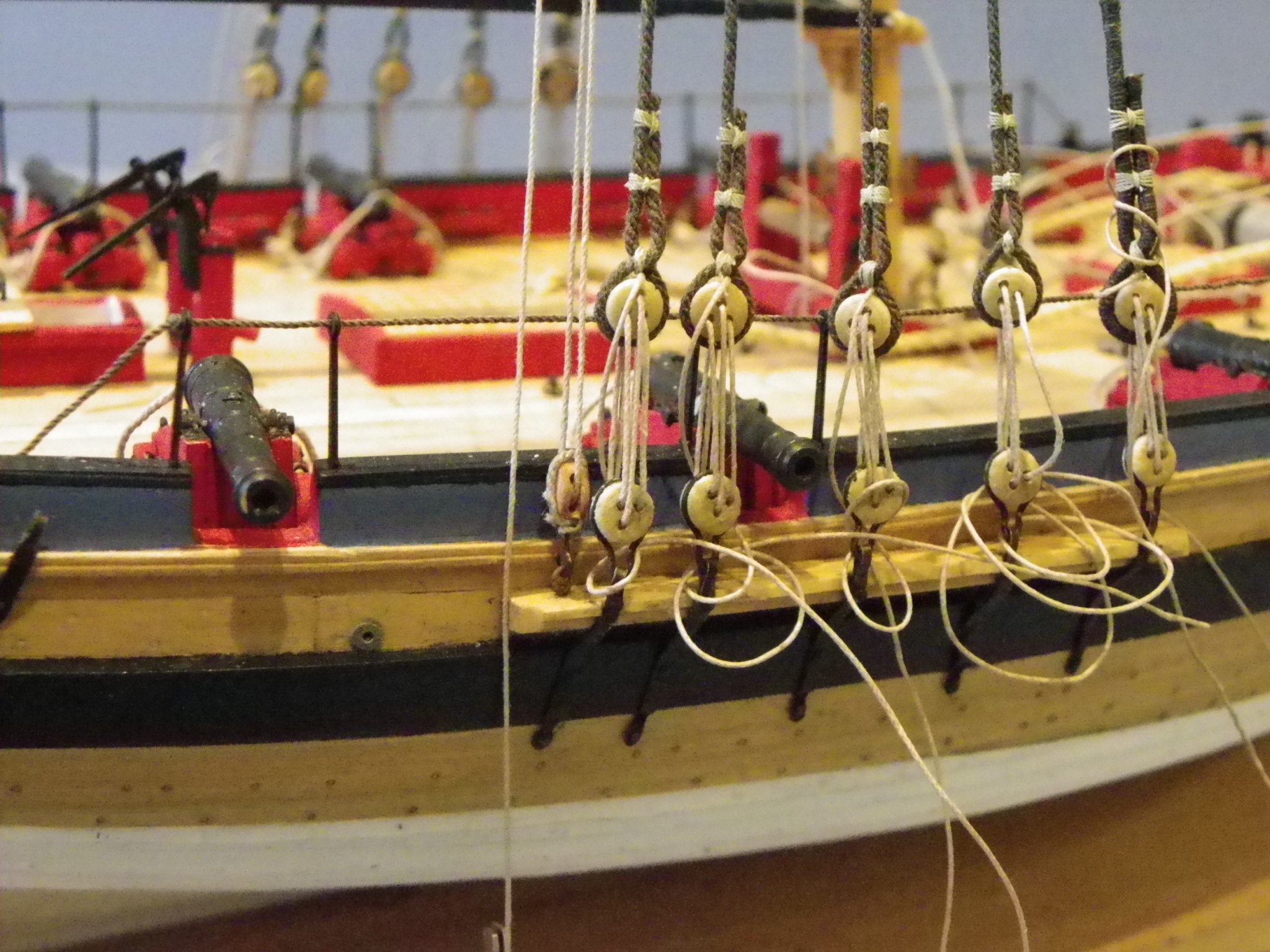
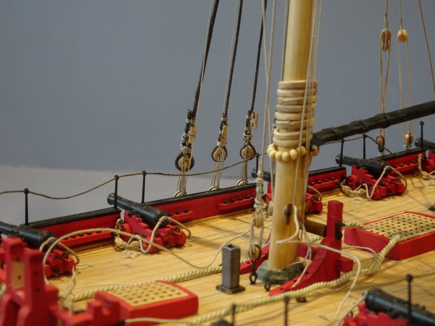
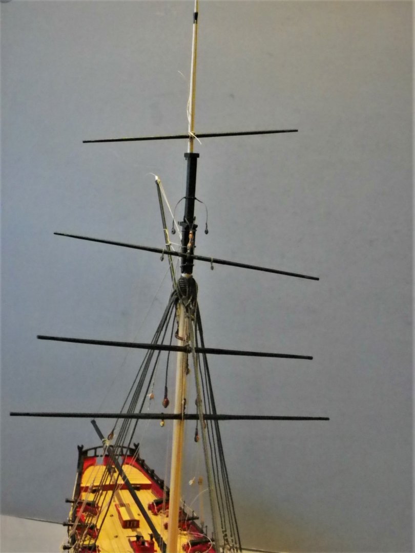
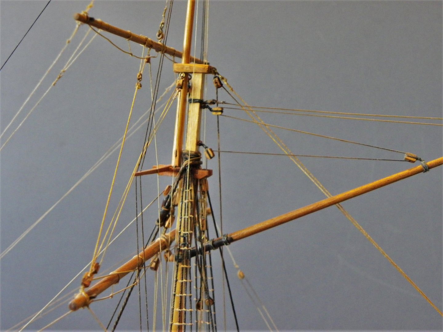
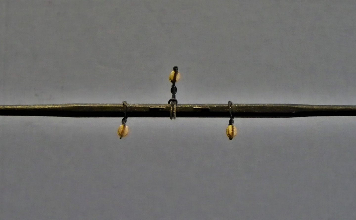
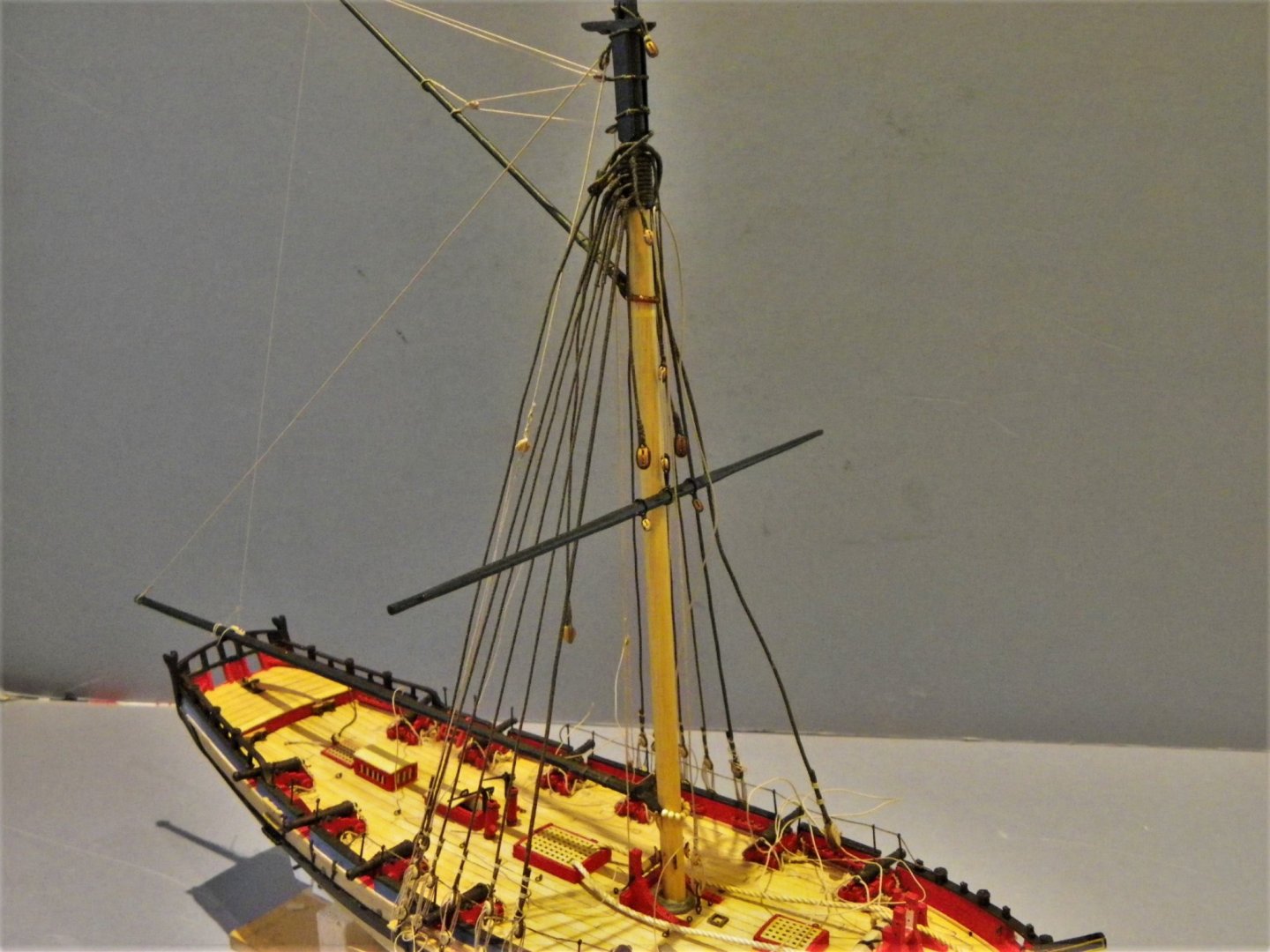
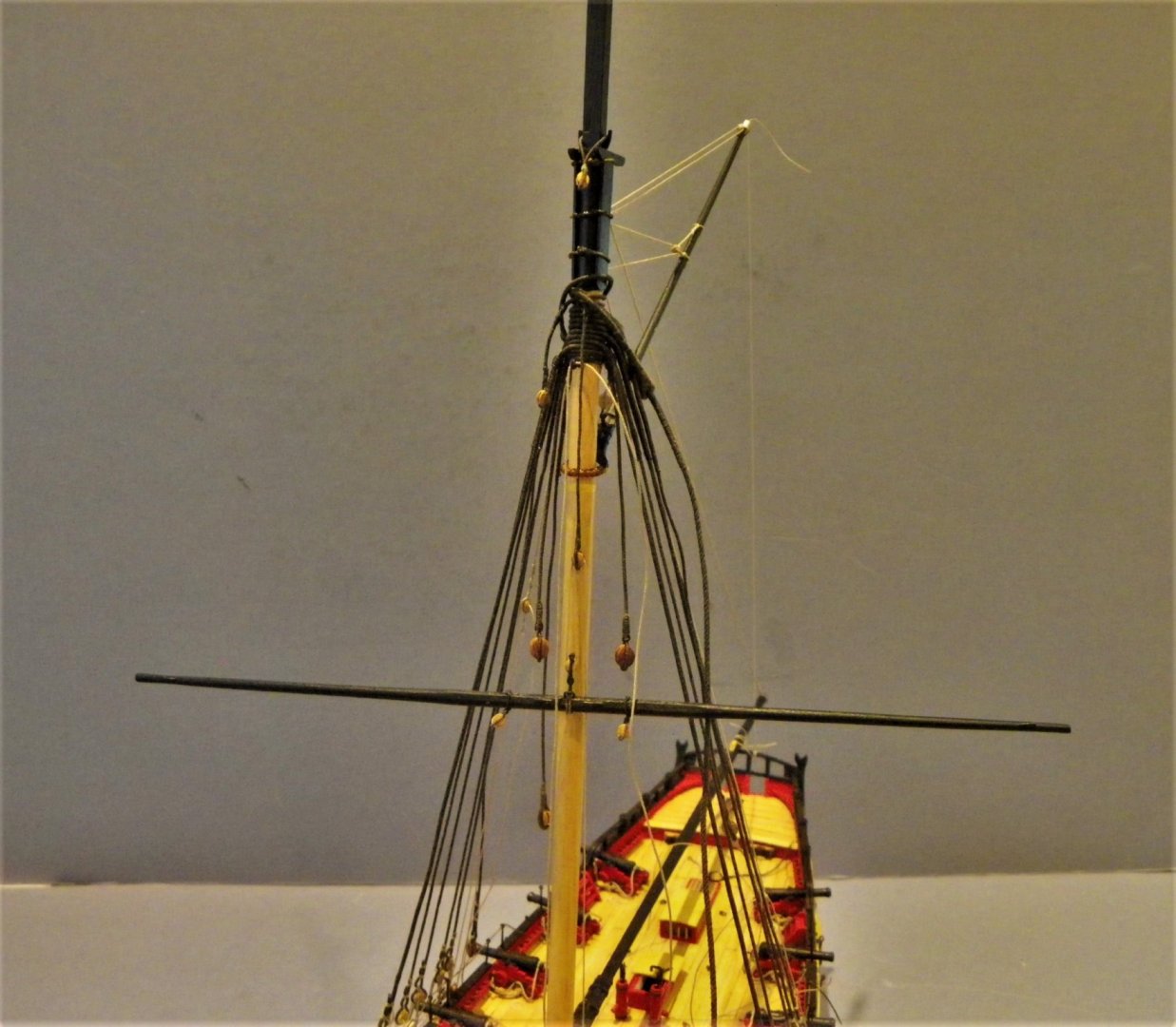
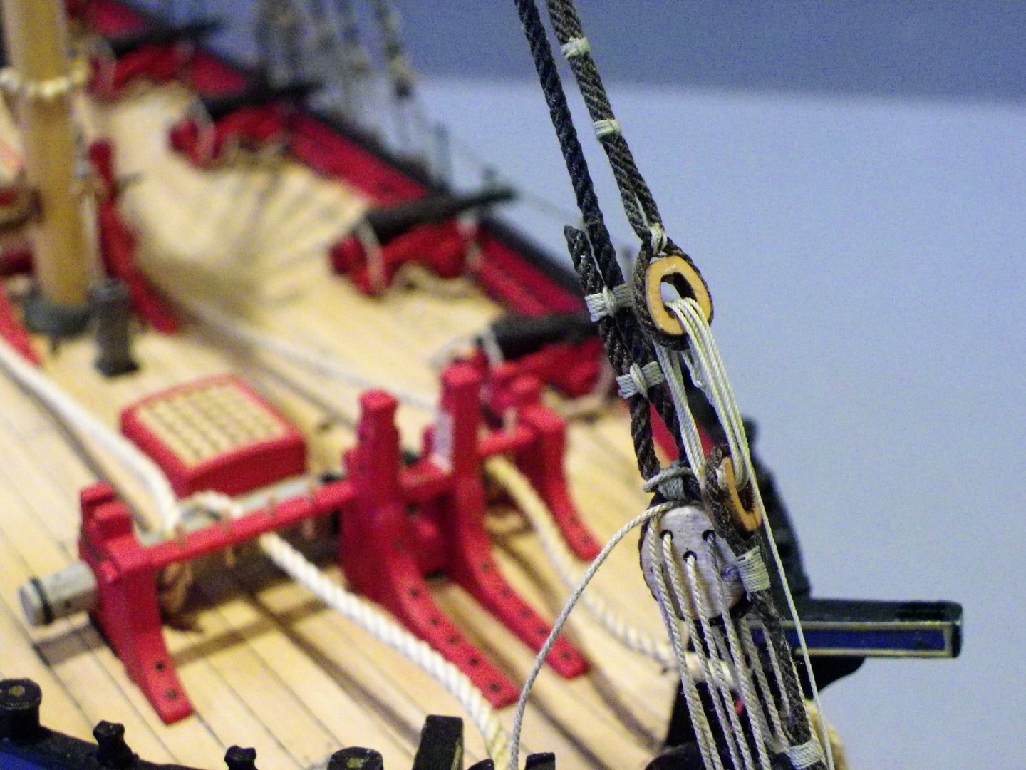
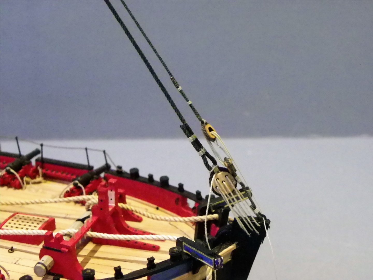
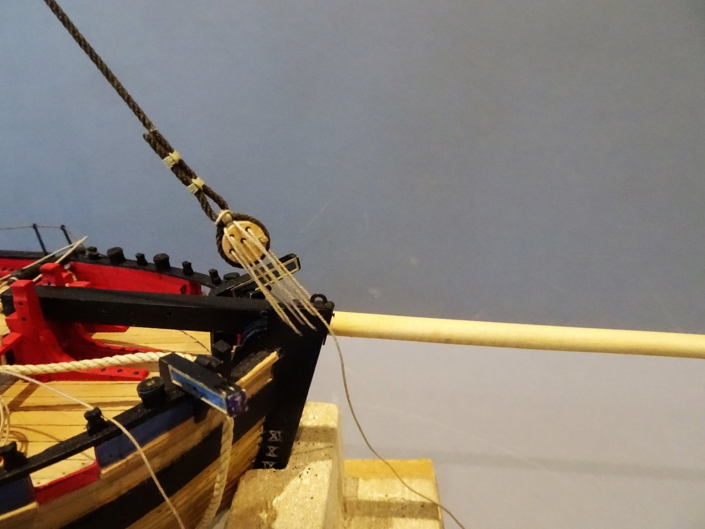
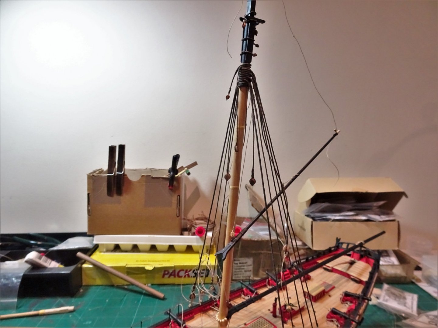
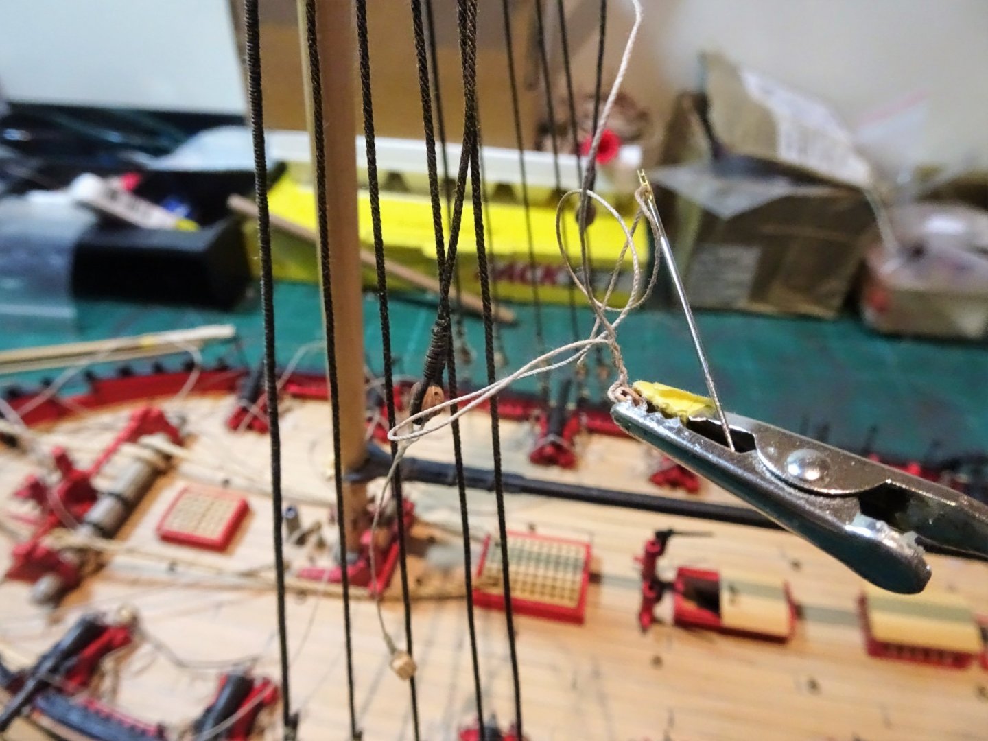
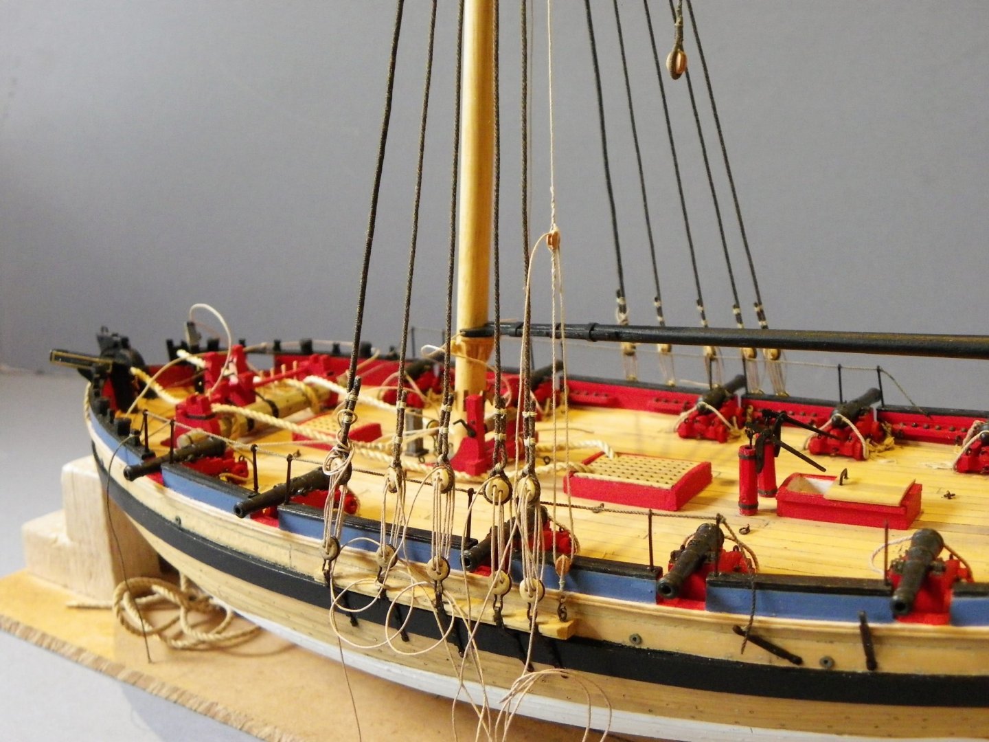
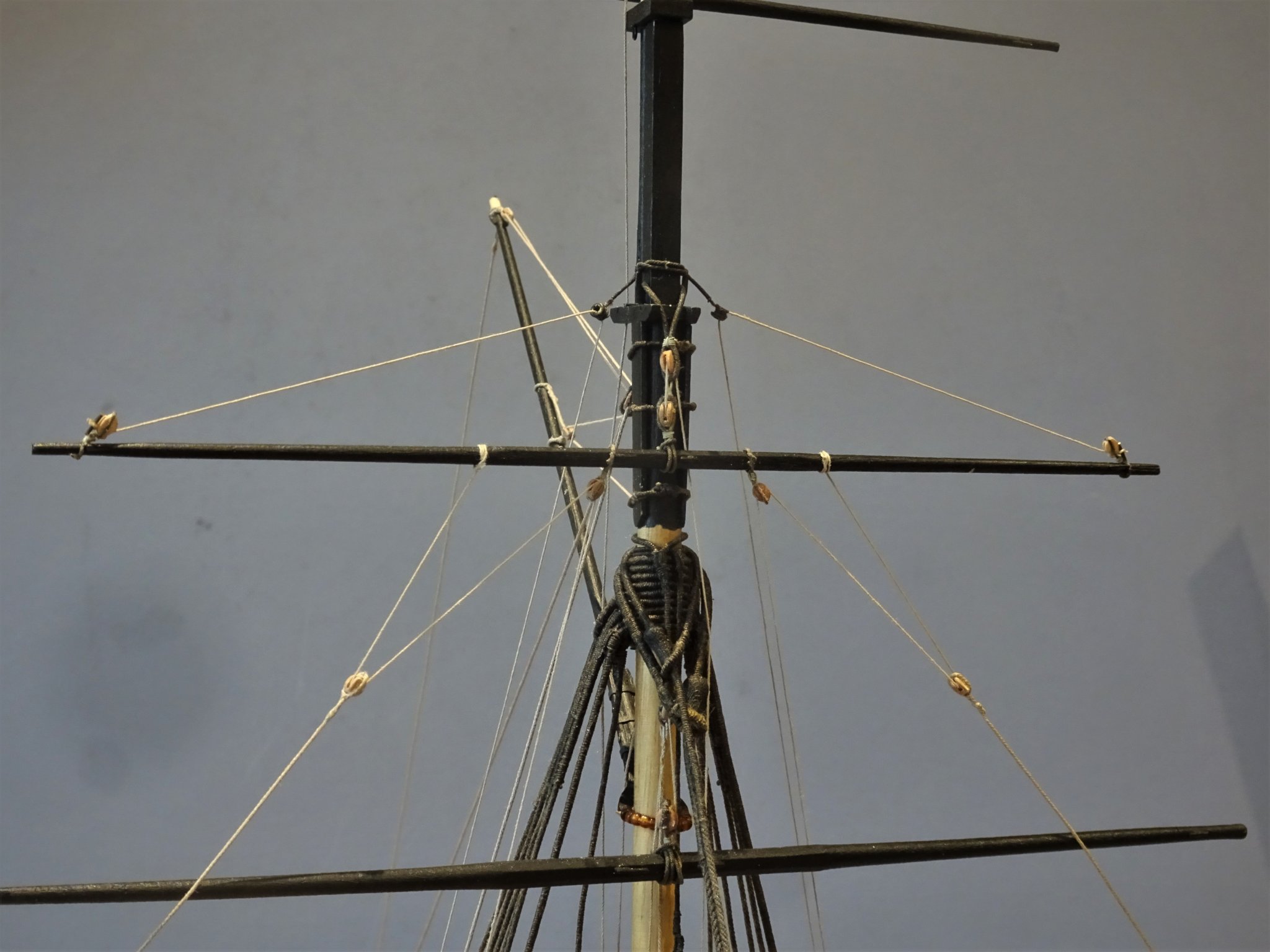
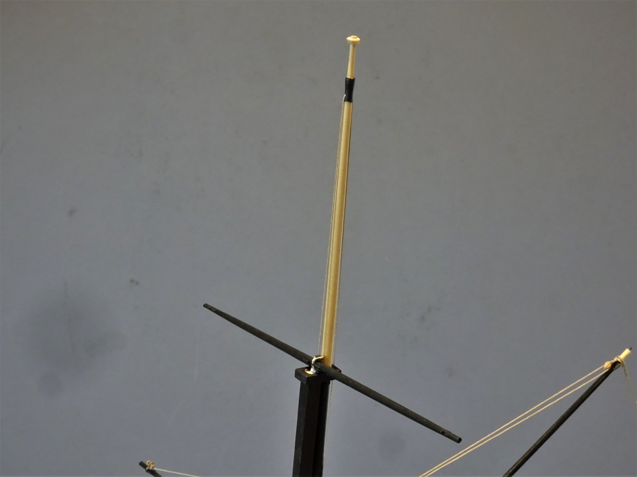
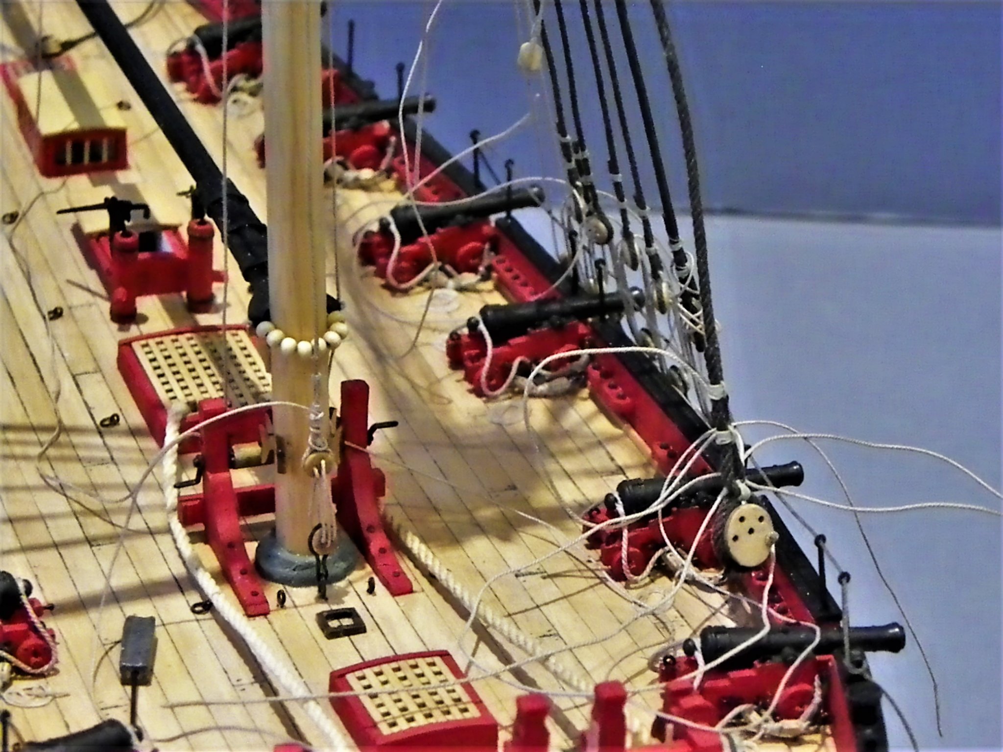
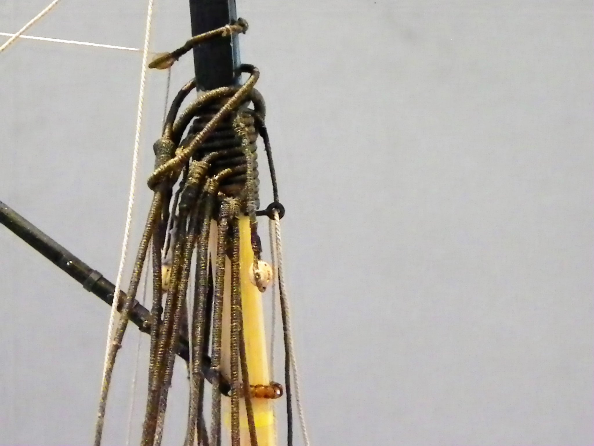
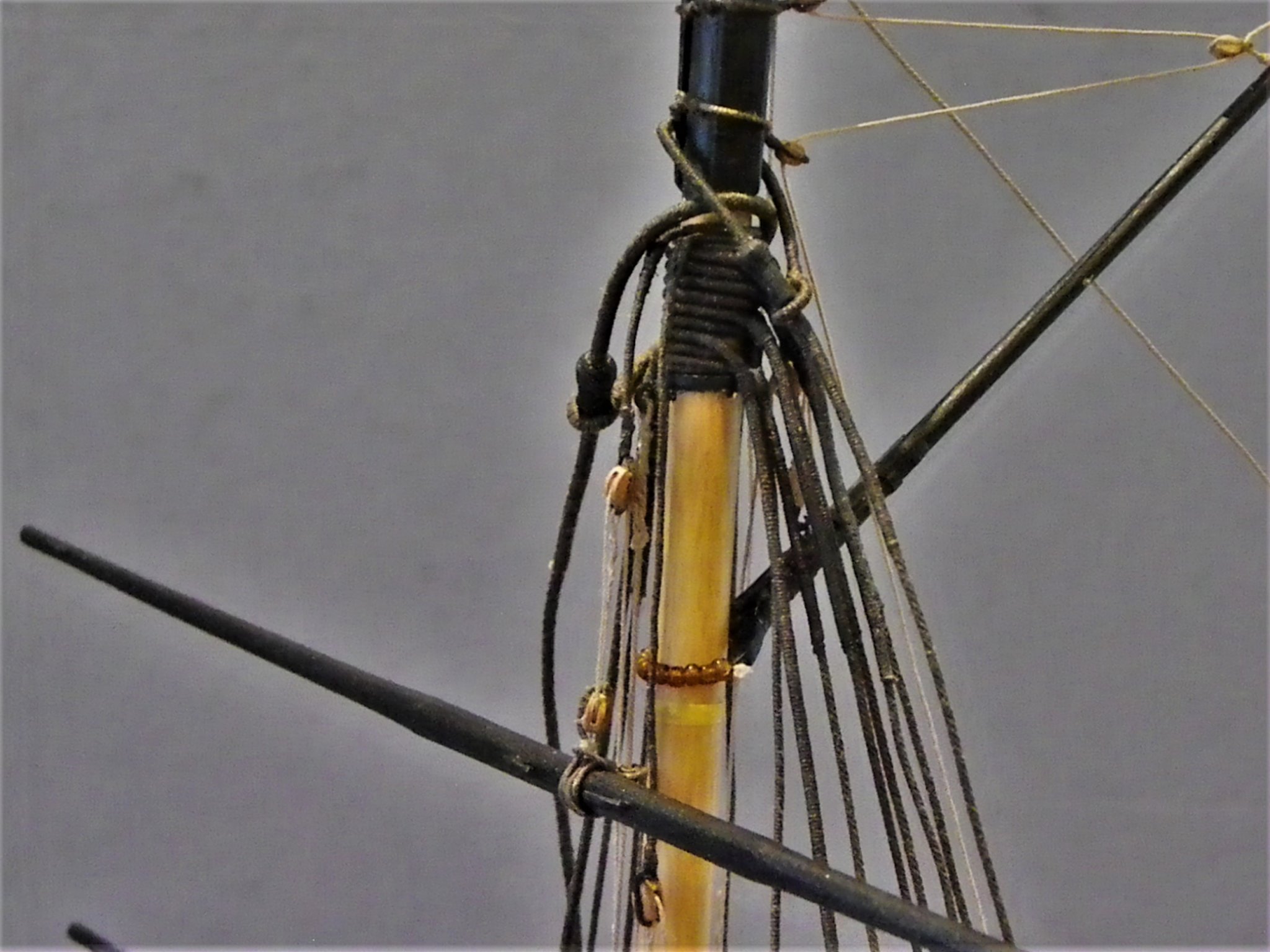
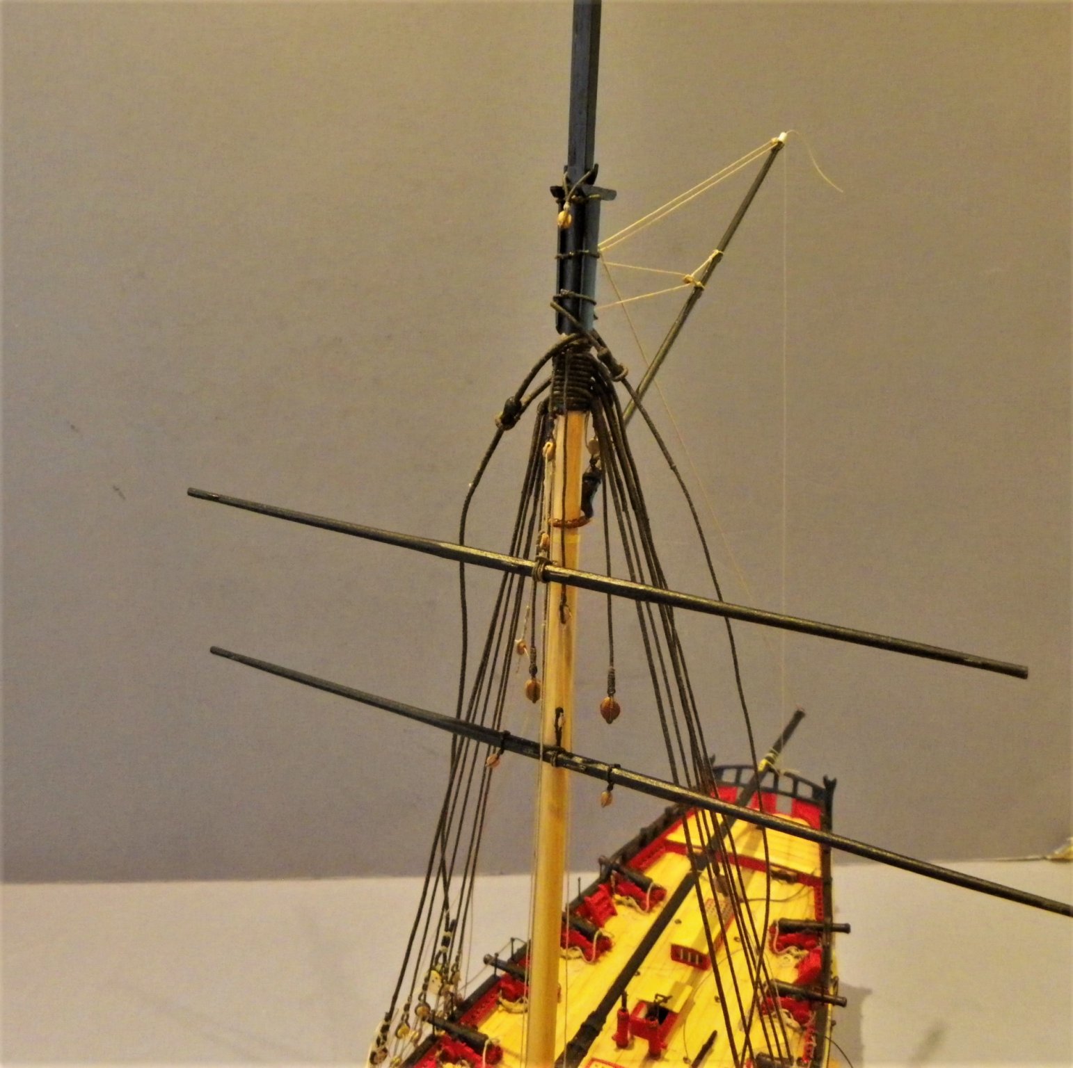
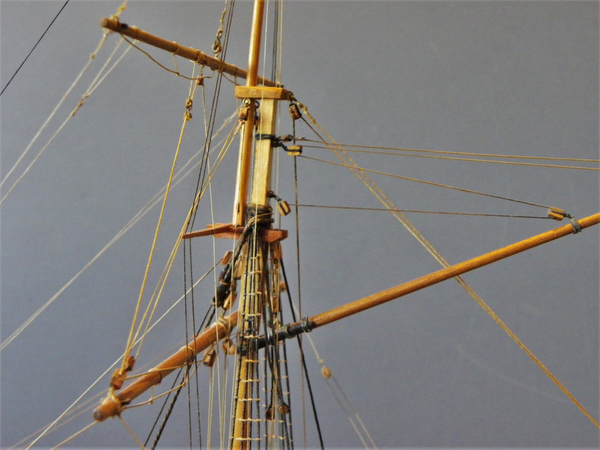
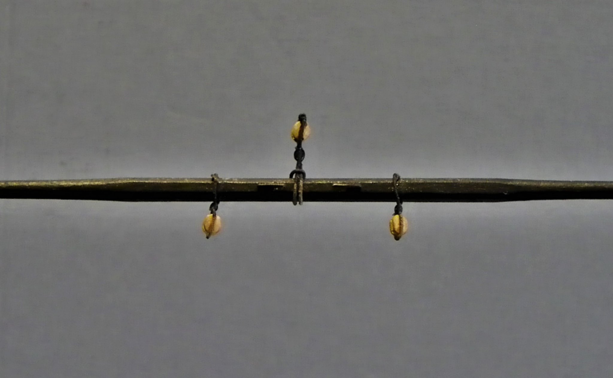
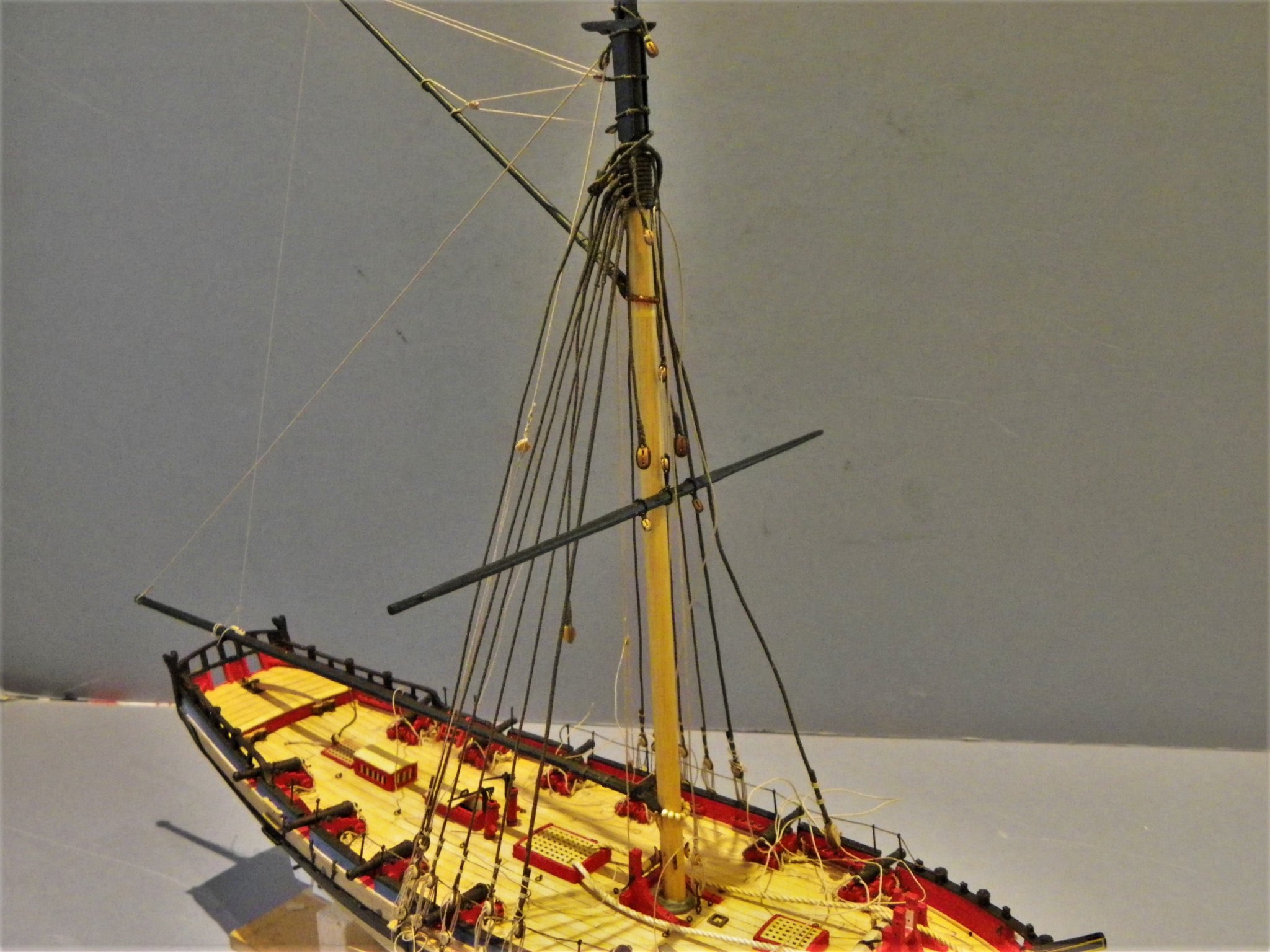
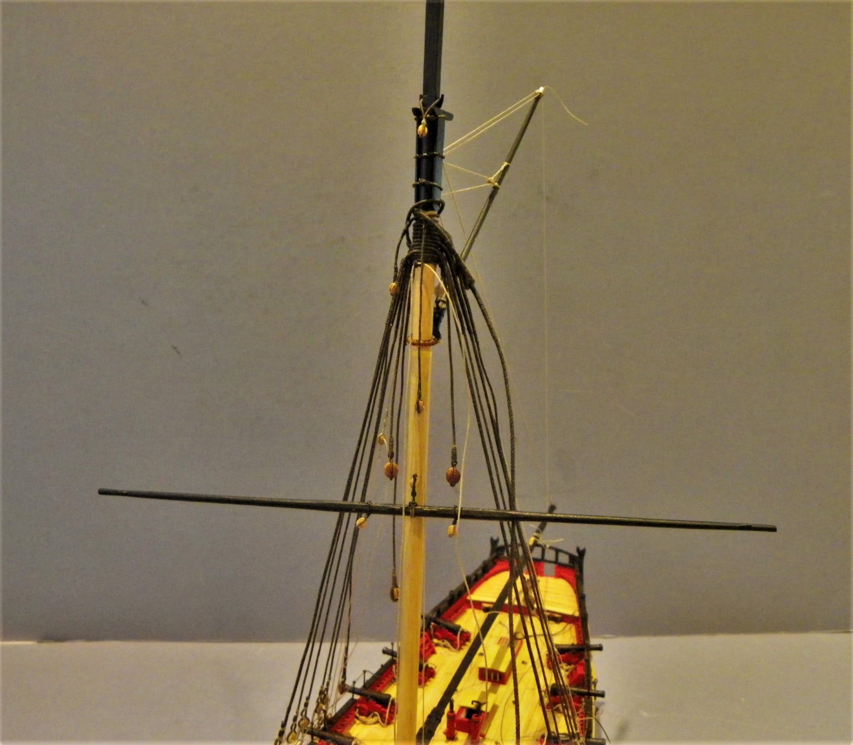
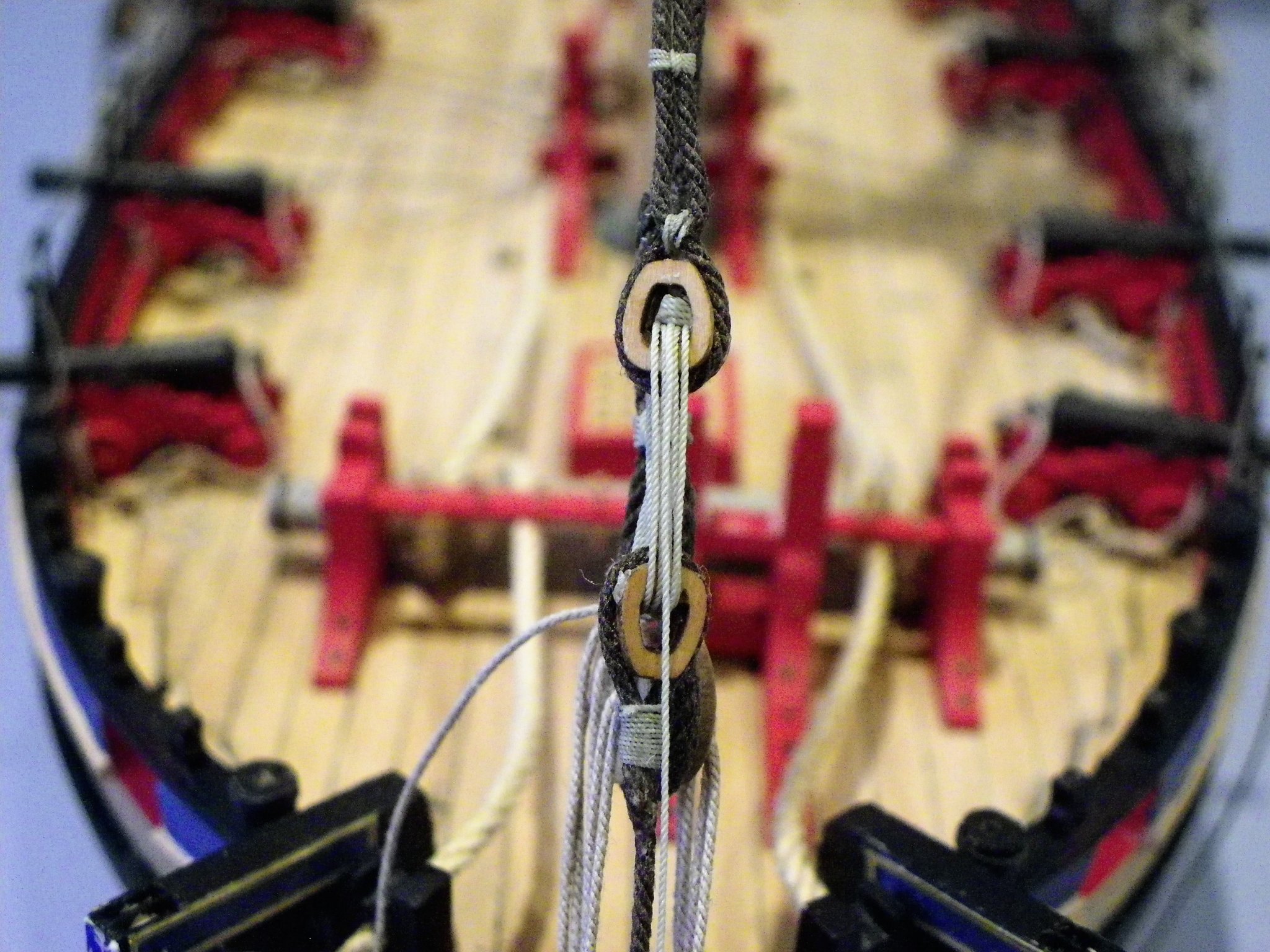
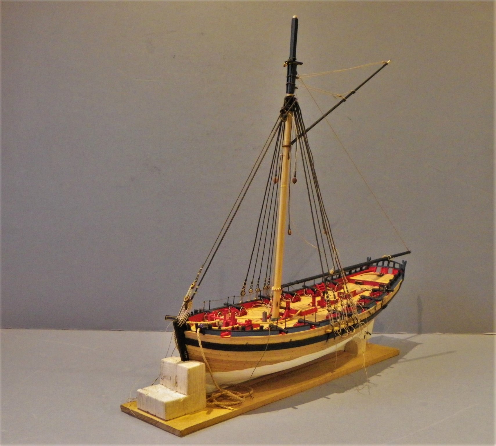
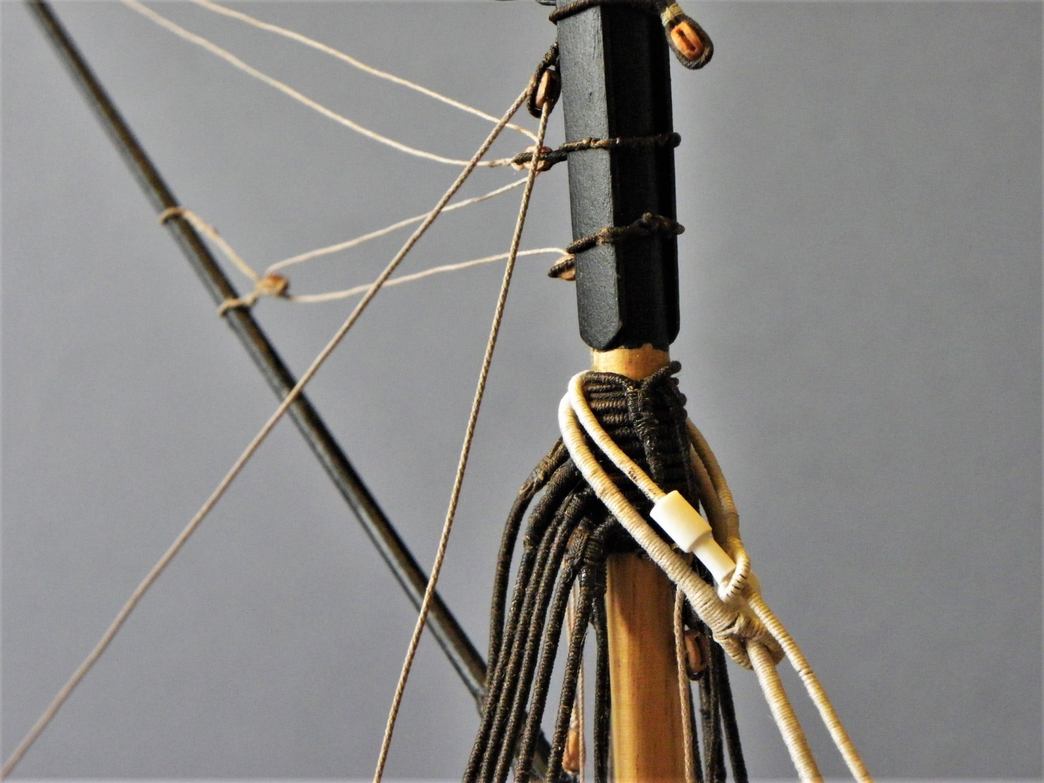
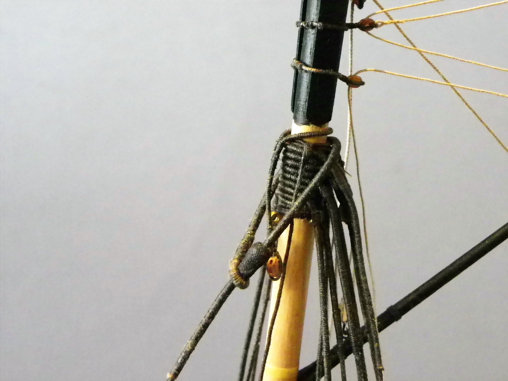
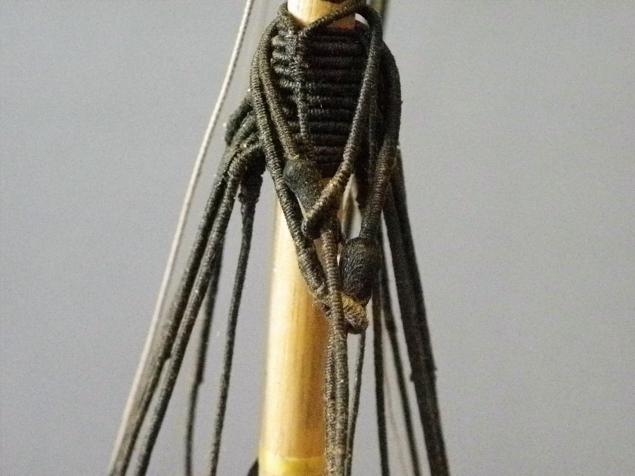
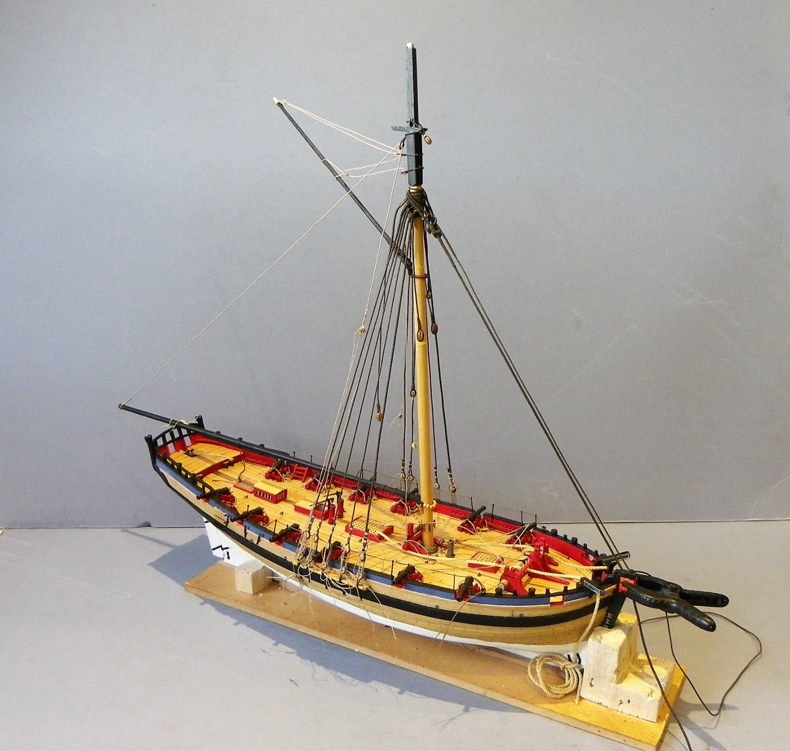
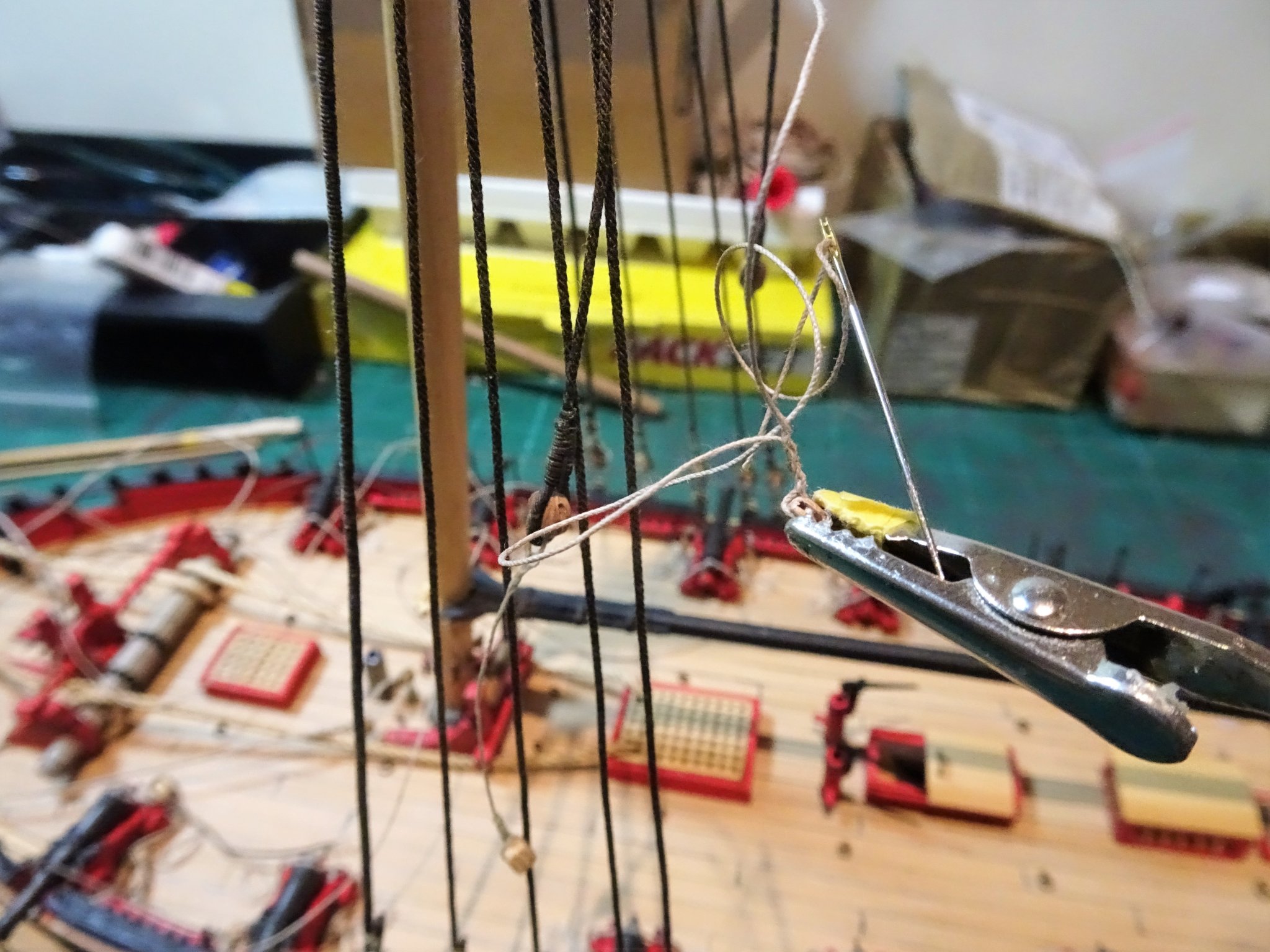
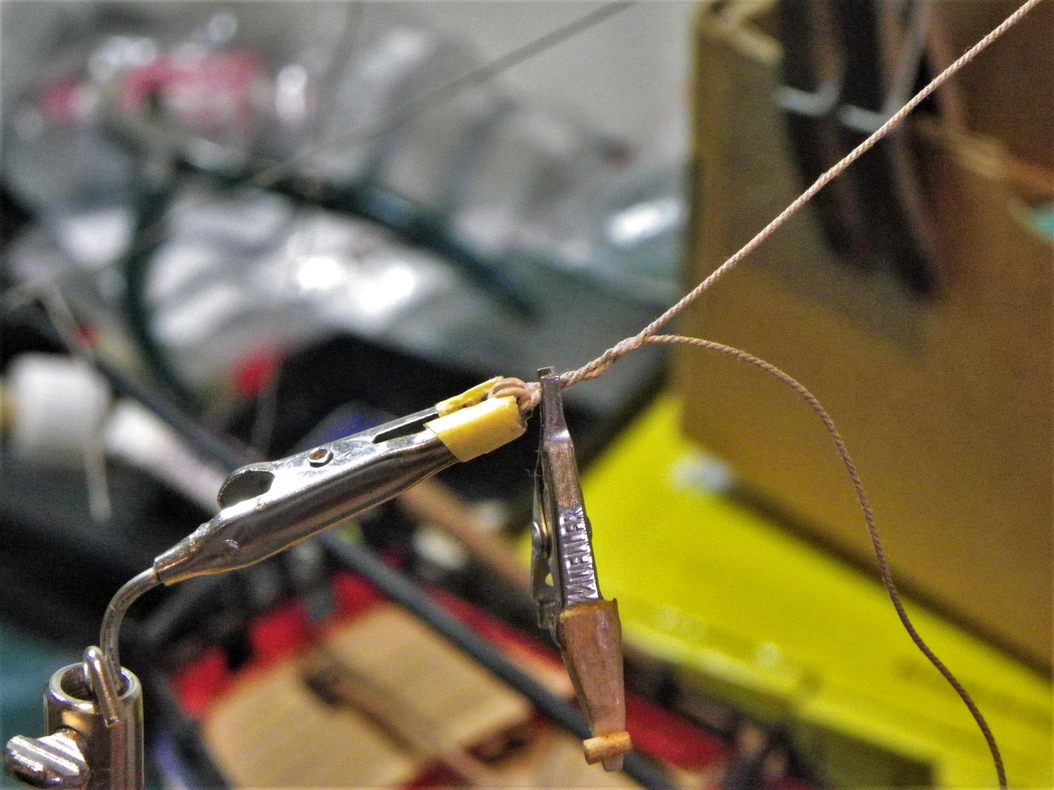
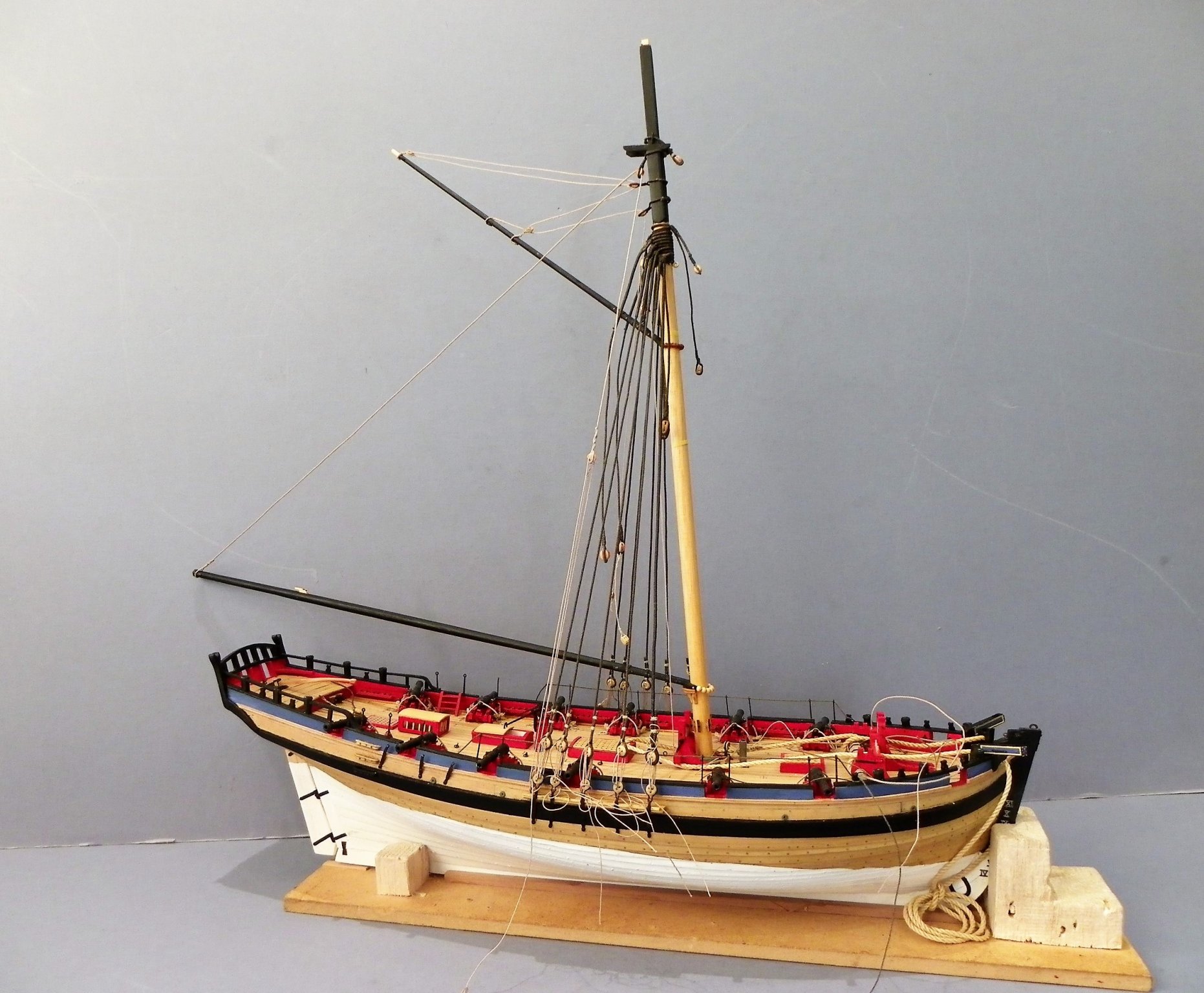
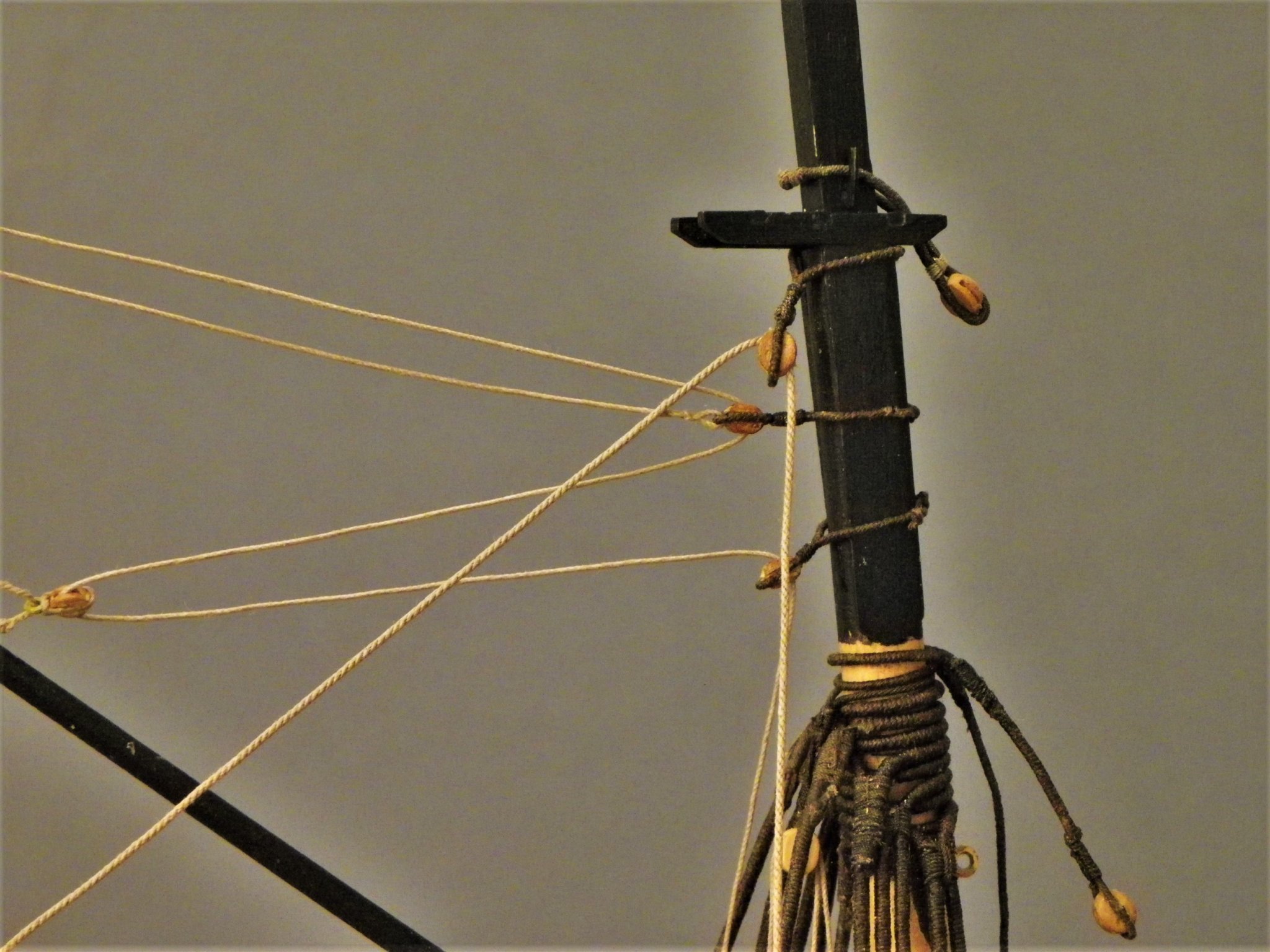
 Thank you Michael 🙂 Post 72 Time for a general tidy-up Over the past few days I have been attending to sorting out some of the rigging jobs and tidying up lines. 4507 The running backstay tackles have been completed with hooks to attach to the iron hull plates. 4513 The Stay and Preventer stay lanyards are now in place. Topsail Yard In addition to the centre tye block, standing clew line blocks are required. 4514 The given 3mm blocks indicated in the kit instructions are about right for size at scale. The kit shows a truss to secure the yard to the mast. Apart from the historical evidence indicating to the contrary, such a fitting would need to be quite slack to allow movement of the yard. On a model however, it would help stabilise the yard and make rigging easier. I fitted the halyard tackle with a 0.20mm line running down to the deck to belay on a port side mast cleat. 4517 At the yard arms are the two T’gallant sheet blocks also 3mm. Secured around the Topmast head above the Topsail yard are blocks in a span for the T’gallant sheet falls. The Alert Book once again has contrary information; drawing H6 shows blocks in a span, whereas Drawings H9 and H22/1 (close detail) indicates thimbles in a span. 4519 It looks to me that the Hawke model has thimbles so I will go with those. It is easier to do this before the mast cap is put into place, that way the span can be formed off model and then slipped over the masthead. Completing the T’gallant mast and Yard 04531 A sheave has been added to the mast for the yard halyard and a truck made for the top. The mast can now be set in place. It shouldn’t be necessary to glue either mast or cap if the fit is correct. T’Gallant Yard This is a simple affair which apart from the central eye spliced tye has no other fittings before the yard is raised. The only controlling lines are the Bowlines running forward to the Bowsprit end which will hold it square but there are no aft running lines to counter the forward pull. Without the benefit of trusses and pins, stabilising the yards becomes a delicate balancing act. 04516 The first thing to fix are the topsail sheets and clews. Attaching the sheets holds the spread-sail yard down whilst the clews pull the topsail yard down and counter the pull of the sheets on the spread-sail yard. Even at this stage the yards are held square to the mast, but the later addition of braces and bowlines will secure any lateral movement. The T’gallant yard is the most difficult yard to stabilise. I may have to resort to a small pin to hold it against the mast to get the required tension on the Bowlines. Boom sheet So, I can finally set the Boom topping lift I now need to attend to the boom sheet tackle, to counter the pull of the lift. 04504 For this I am using 4mm double and single blocks coupled with 0.45mm line for the tackle falls. The shroud cleats have now been attached. 04510 Tricky little beggars to get in place inside the shrouds, I hold them in place with pva and then add the lashing. 04535 Before I make any permanent attachments to the cleats I need to attend to the rattlin’ down otherwise I will be working around lines running inside the shrouds which is not ideal. 04524(2) 04526(2) Starting to look a little more ship shape now, but there’s still a way to go. B.E. 21/02/2020

.thumb.JPG.6d9fe766ed66b4b2968e582de197066e.JPG)
.thumb.JPG.4e5b625ba5bbdaf89908b190d2539cb9.JPG)
- 335 replies
-
- 26
-

-
- alert
- vanguard models
- (and 1 more)
-
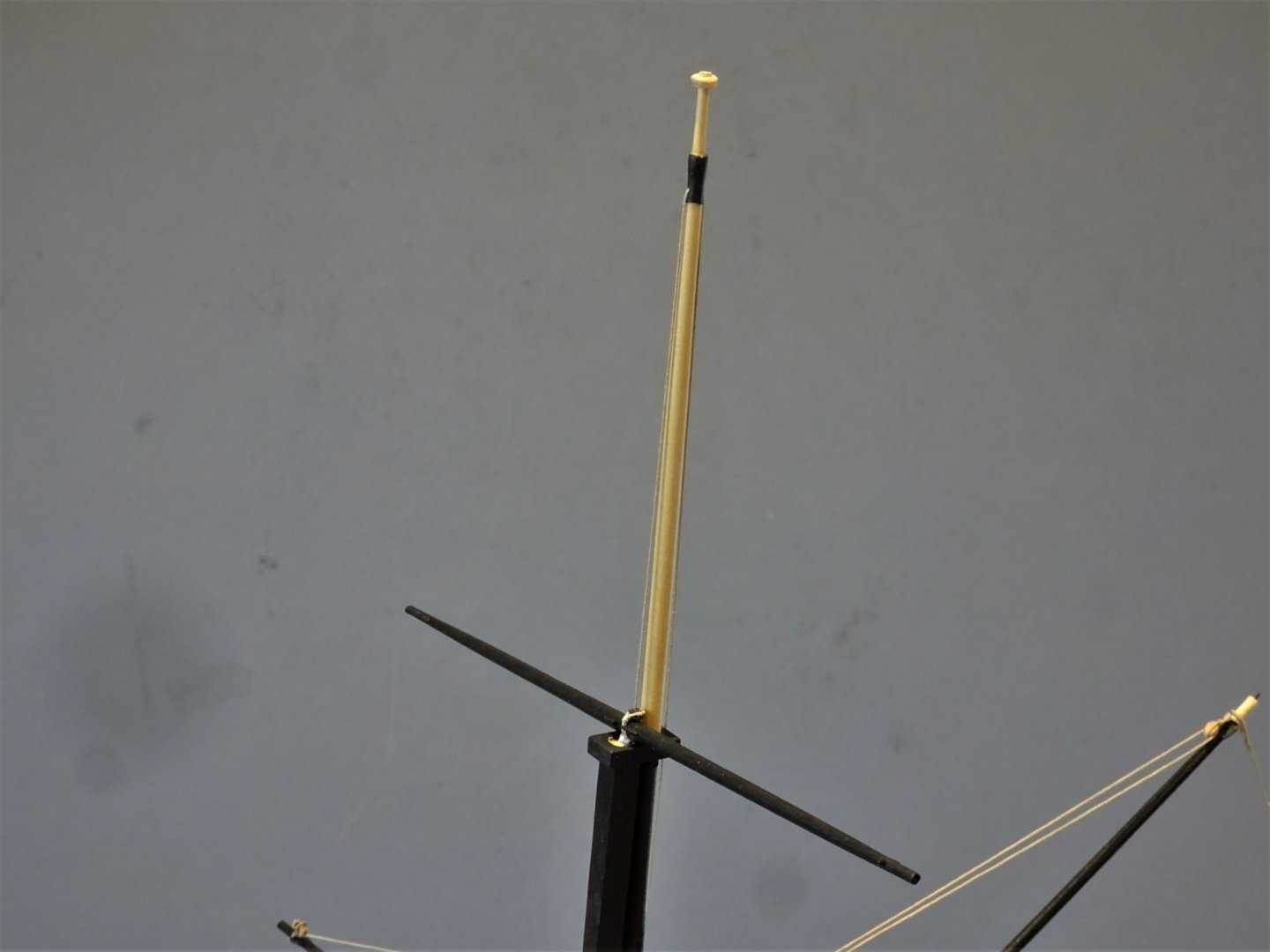
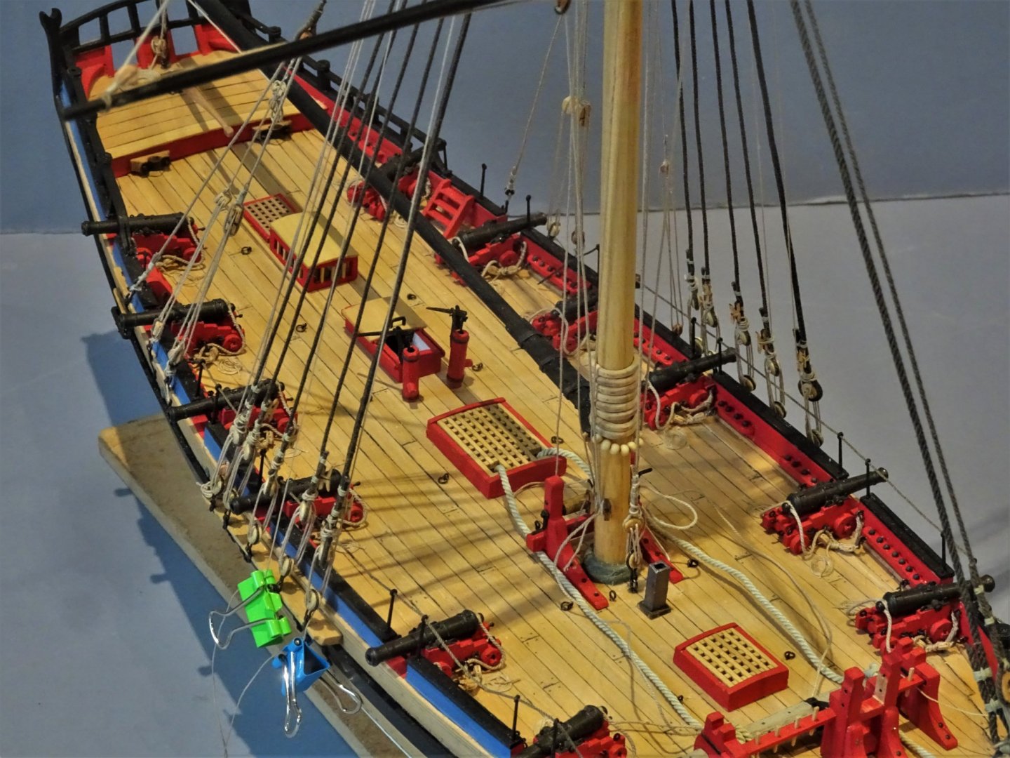
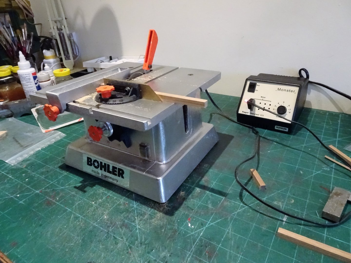
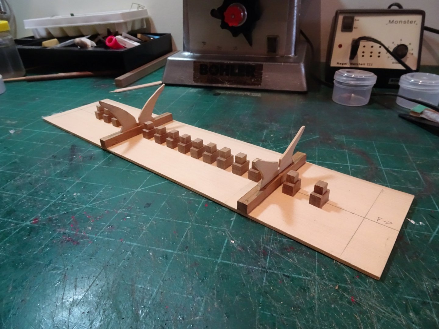
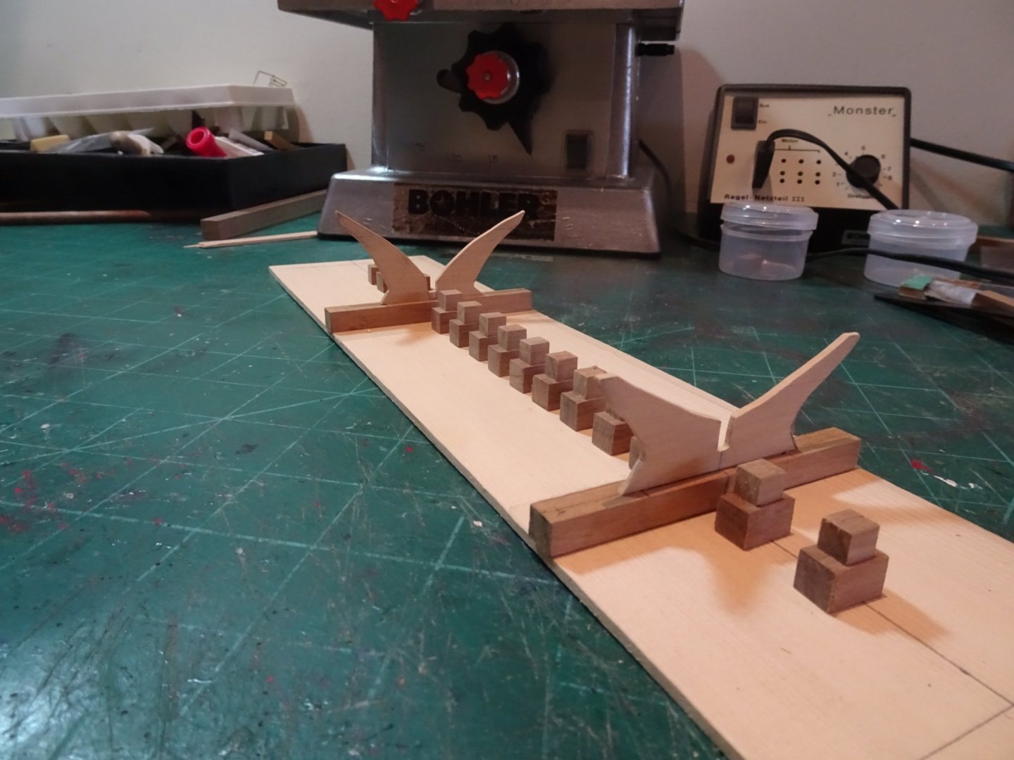
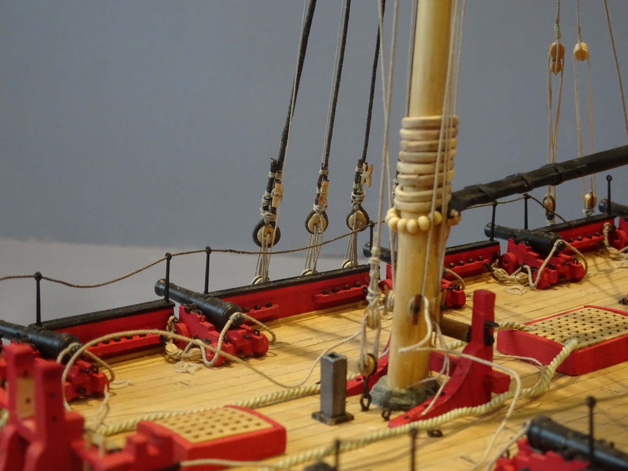
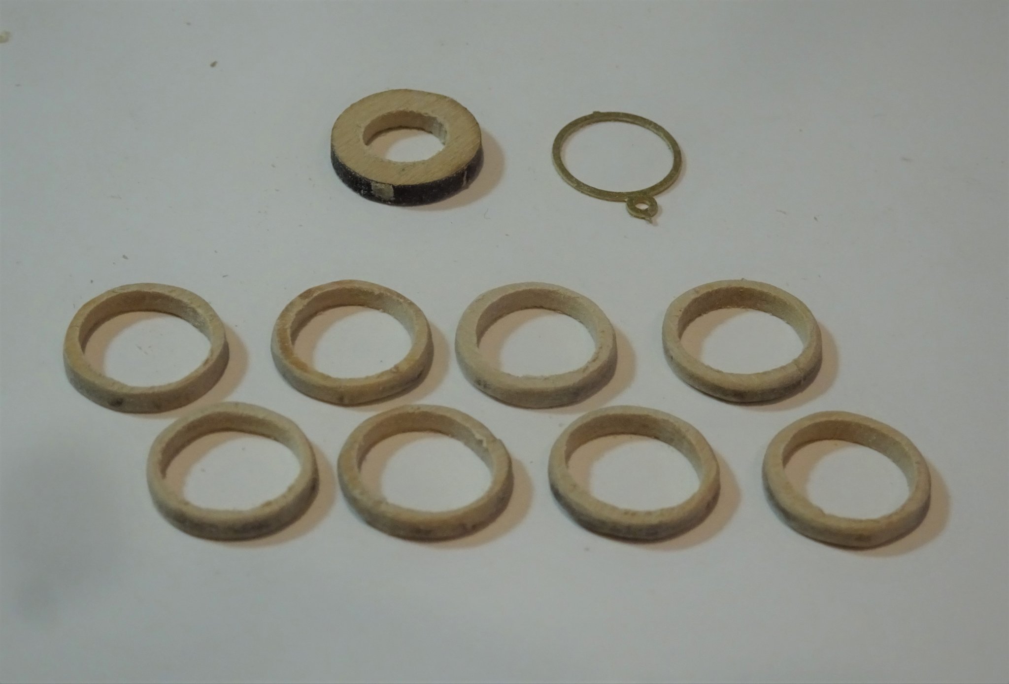
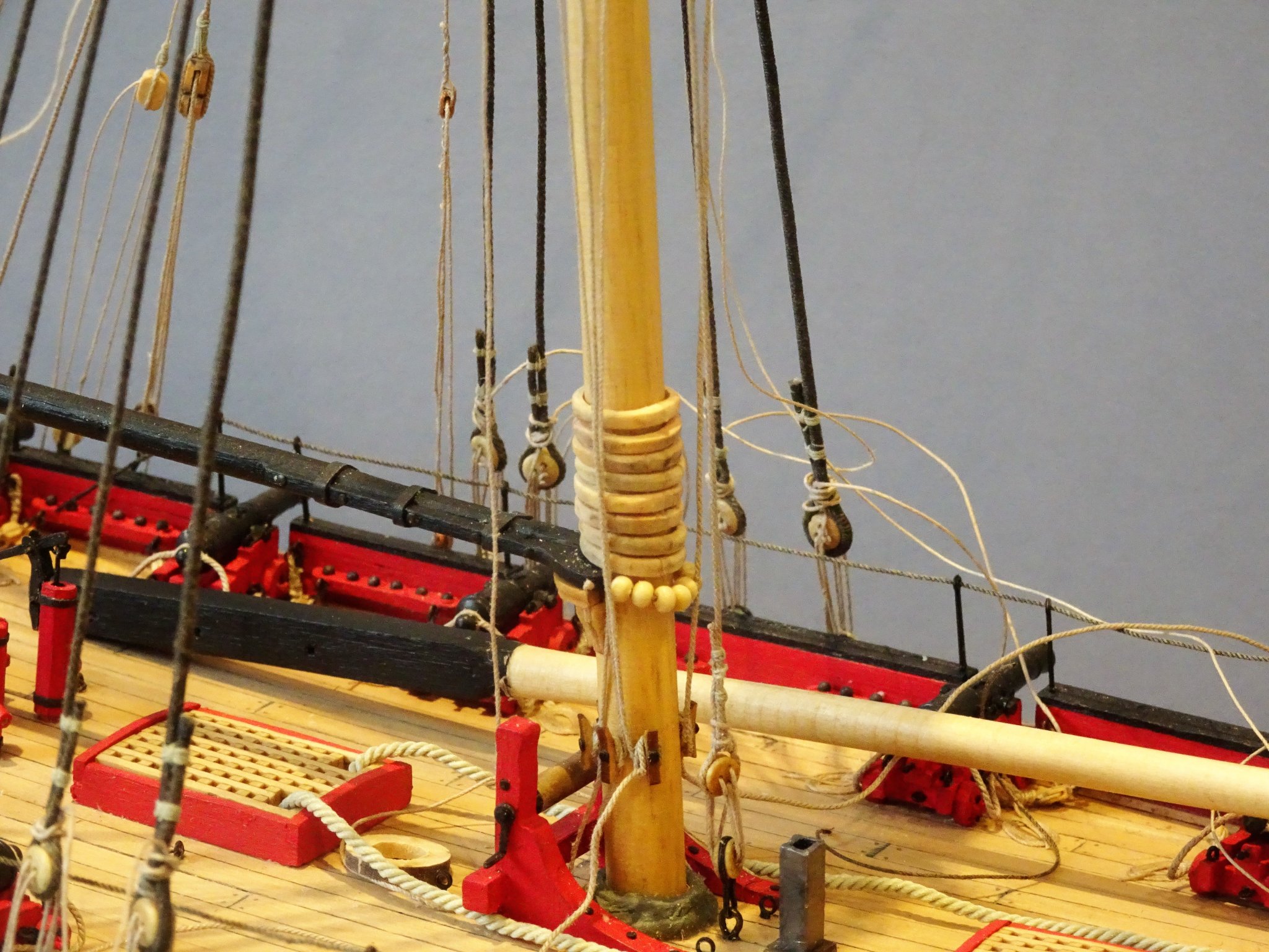
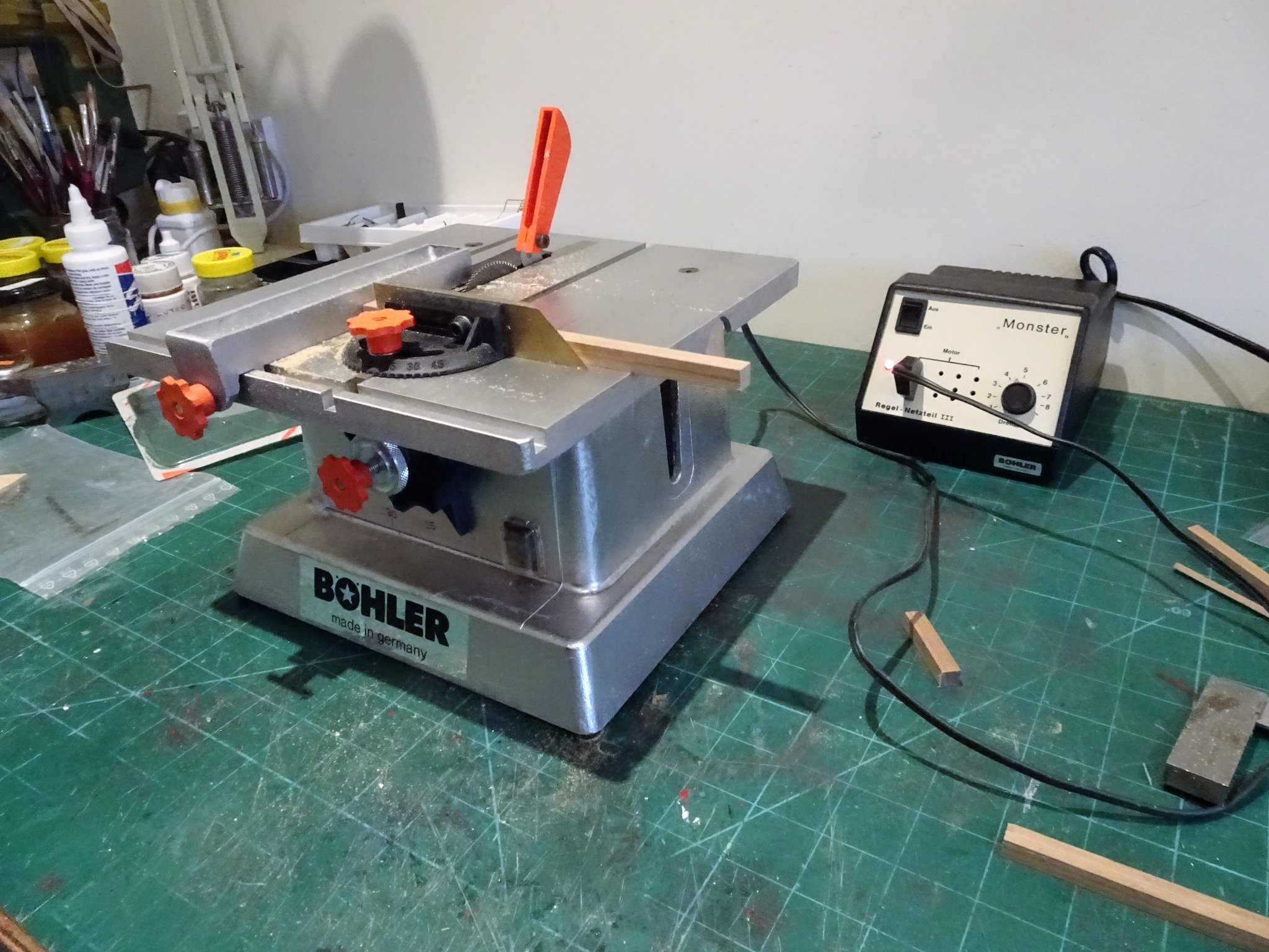
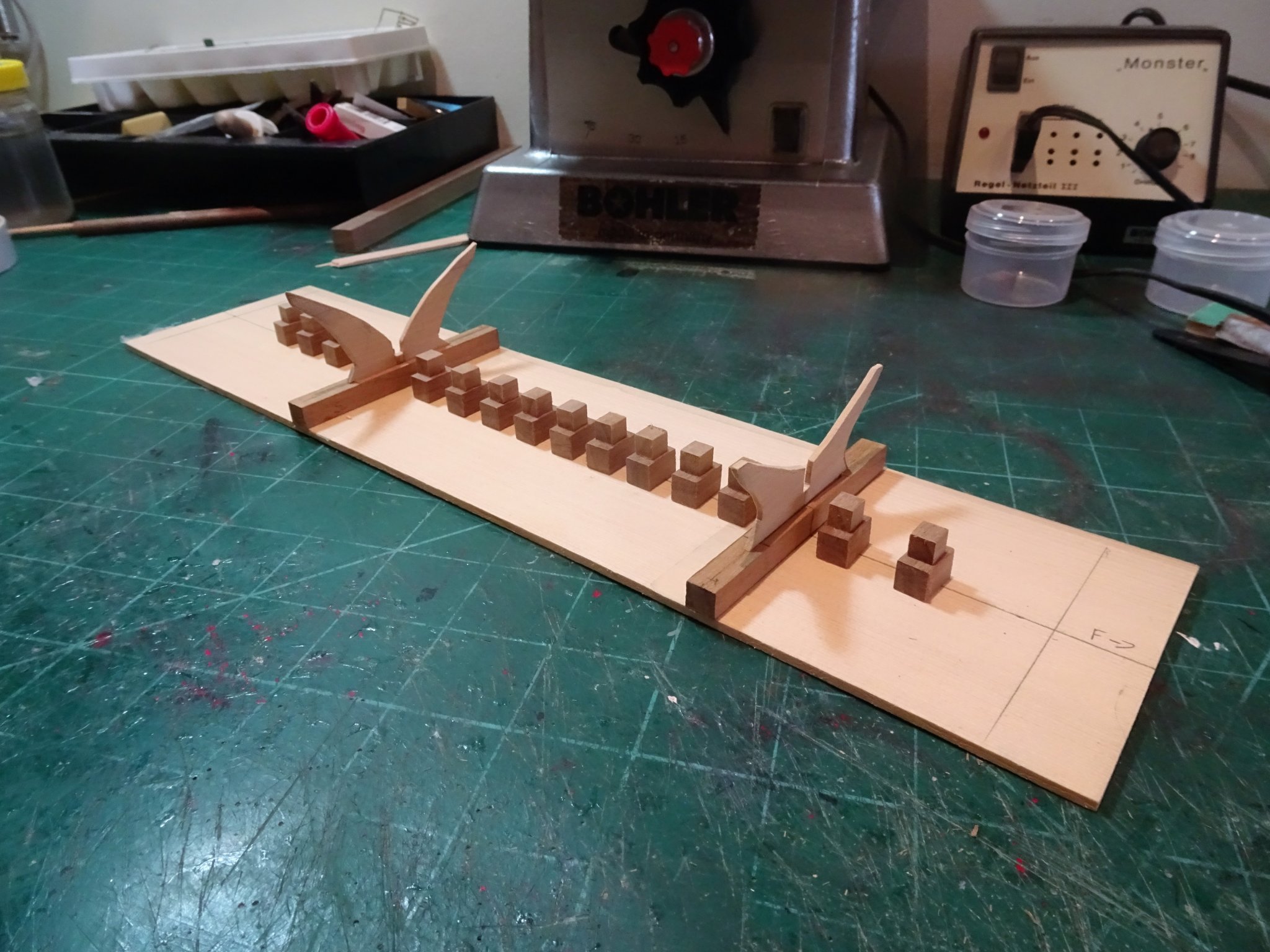
Post 71 A small diversion I’m awaiting a fresh supply of Morope 0.1mm line, in my opinion the finest stuff for small line seizing there is. No other 0.1mm line comes close to it. While I wait, I can attend to a few outstanding details. Mast Hoops Finally got around to making the mast hoops, I didn’t really like the thin etch brass versions, and initially I was in two minds whether to fit them. During my Cheerful build I recognised that the centres of the Syren laser cut mast hoops would come in for hoops of a lesser size should the need arise. 4480 Well the need has arisen by my belated decision to add these as they do provide added interest to the build. The hoops were drilled out and filed to size, the main downside is having to cut them to retro fit to the mast. 4486 A tricky business with the yard halyards in place but at least they’re not glued to the cleats, so the tension is easily re-adjusted. 4496(2) Shroud cleats Alert doesn’t have pin racks along the bulwarks, possibly because there are none 😉, but etched shroud cleats are provided. 4484(2) Syren 5mm Boxwood shroud cleats before fettlin' I prefer to use these, I think they will hold better to the shrouds than the thin etched kit versions. I could have as an alternative legitimately fitted a shroud rack with belaying pins and may still do so depending on how the shroud cleats go. Thinking about a stand, My preference is for a stylised keel block arrangement with cradle support of minimal dimensions but sufficient to support the model. 4500 The Bohler makes quick work of cutting the blocks. 4501 The cradles are cut from some 1/16th Boxwood sheet, and the keel blocks from some 8mm and 5mm Walnut square stock. 4502 Setting out the alignment of the supports, the blocks will need to be individually fine tuned to fit beneath the keel, but this can wait until later once I decide on the permanent base. B.E. 19/02/2020

.thumb.JPG.8edc2dfcfad24ab83d511512f1cf84dd.JPG)

.thumb.JPG.7cb949251b941662f943bbd2beb22697.JPG)
- 335 replies
-
- 17
-
-
- alert
- vanguard models
- (and 1 more)
-
I would have to agree with Spyglass, you're never going to get a satisfactory job on that basis, remove the planks and start again. Use a temporary plank to check the fairing at all levels down the bulkheads; the amount of plank tapering you have towards the stern looks far too much, I don't think I needed to taper very much at the upper stern on the first planking. B.E.
- 436 replies
-
- 2
-
-
- vanguard models
- alert
- (and 1 more)
-
Great find Nils, I look forward to seeing you work your magic on her. 👍 B.E.
- 38 replies
-
- 3
-
-
- billing boats
- hjejlen
- (and 2 more)
-
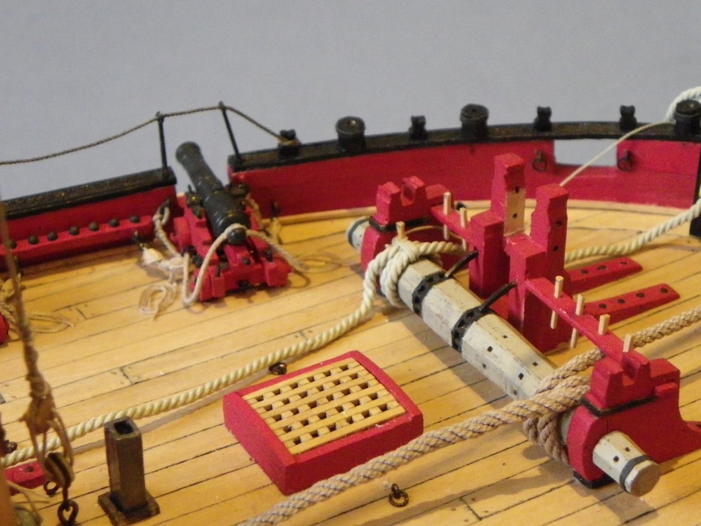
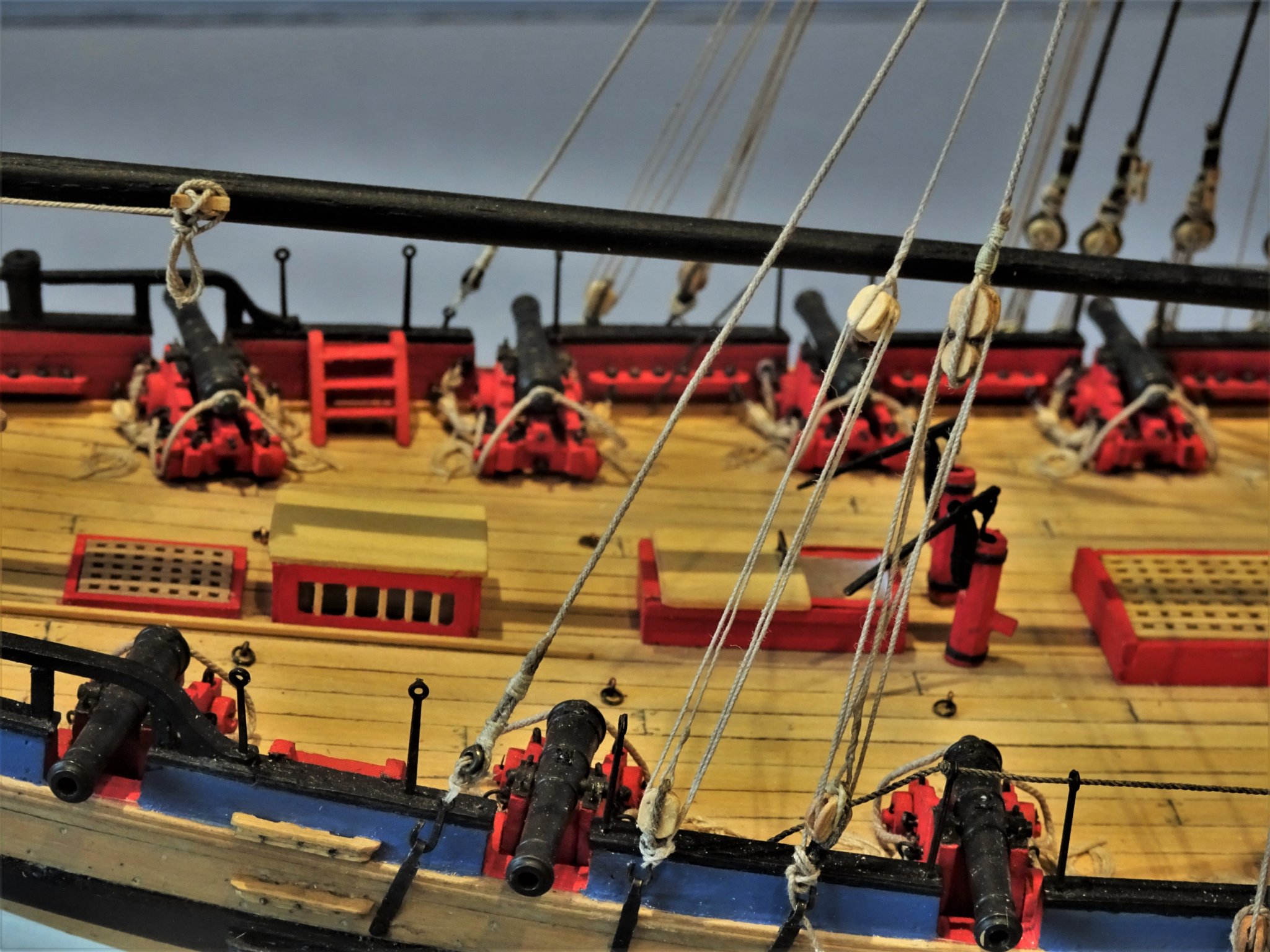
Square holes would be fine for below deck guns, but for 'show' guns round is the way to go. Rounding has never been an issue for me, but the axles should be sufficiently long to allow for drilling for the axle pin before trimming.😉 B.E.
-
Like the inclusion of the bolt holes in the gun carriage trucks, Chris, nice touch.👍 It's something I like to add, but it's a fiddly, time consuming business by hand with micro drills. Cheers, B.E.
-
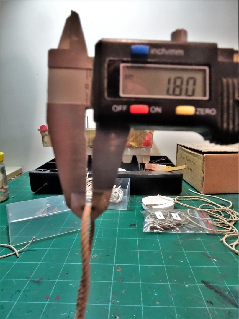
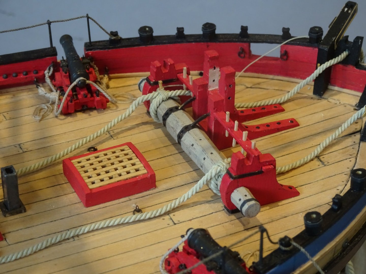
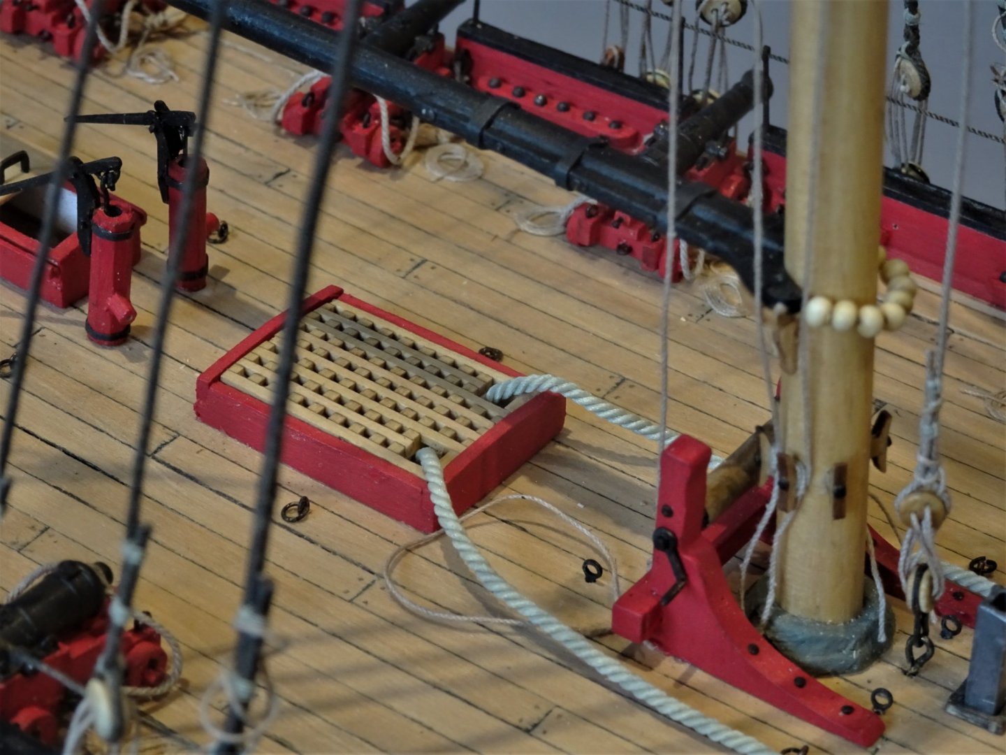
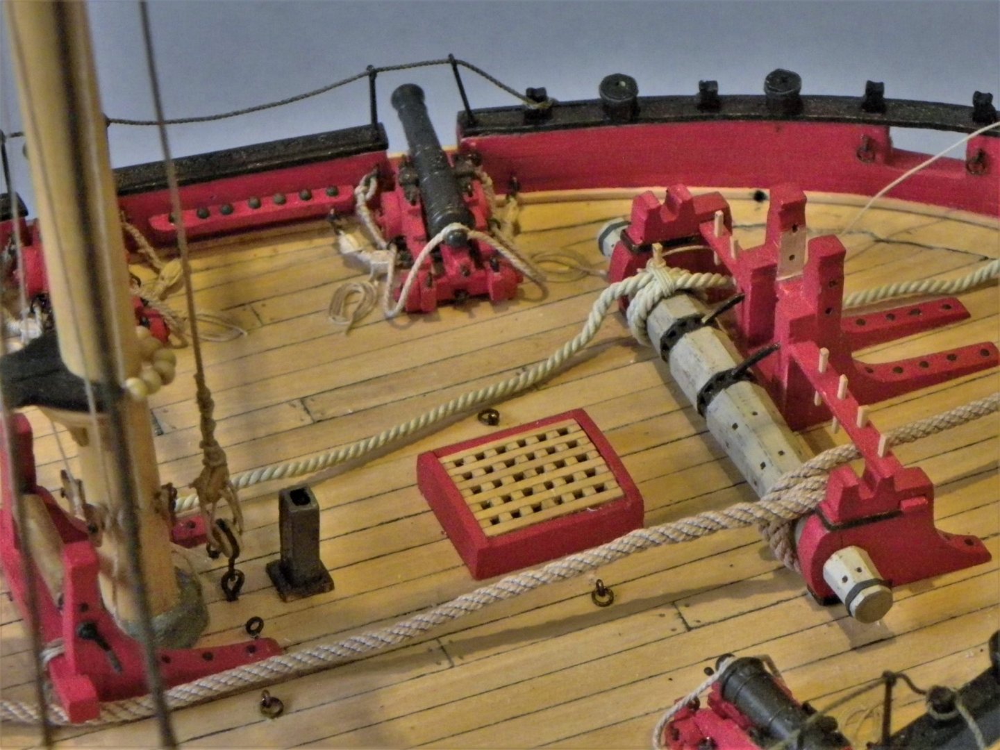
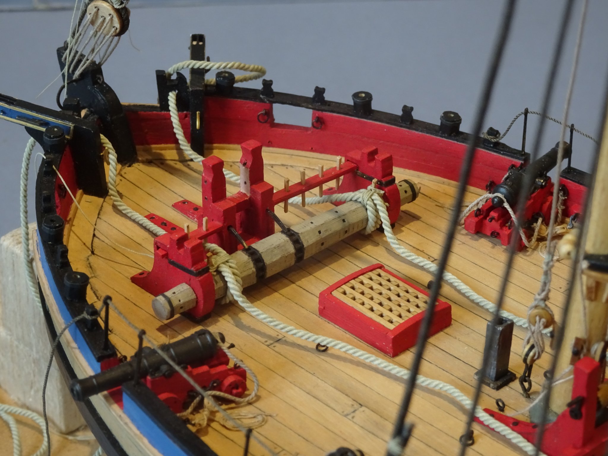
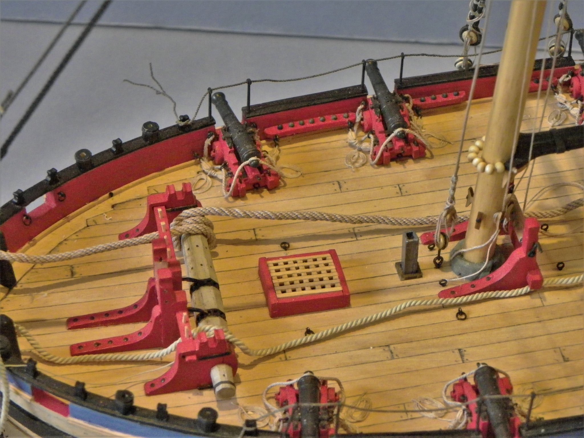
Post 70 Anchor cables I have already had a dabble at setting out the anchor cables using temporary line but with the deck relatively free, now is a good time to set the anchor cables in place. The sizes of anchor cables are not given in Steel’s rigging tables altho’ the associated ropes are. I am aware of two methods of determining cable size. As per Lees:- 0.62 of the diameter of the Mainmast. An alternative calculation:- cable circumference = ½” for every foot of a ships beam. How does this relate to Alert: Alerts Mast is 20” ø x 0.62 = 12.4” circ. which equates at scale to a line of 1.56mm diameter. Alerts beam is 25.5’ x 0.5 =12.75” circ. which equates to 1.6mm diameter. The kit indeed provides *1.6mm line, of excellent quality, and equating to a 12½” circ cable. The 36” length is more than adequate to provide the option of full lengths to run the deck and down the main hatch. Following the arrangement as per Harland (Seamanship in the age of Sail) the cable is taken three time around the barrel with the turns off the top with the inboard end kept to the outer end next to the bitts. This does highlight an issue; the cable looks somewhat large for the windlass barrel and covers up the outer Handspike holes. 4466 I checked the line with my electronic calipers and it is closer to *1.8mm diameter which perhaps explains the over-scale look. This is quite frustrating as I do like the quality of the provided cable. The Alert Book indicates an 11½” cable which scales to 1.45mm ø I have some Morope 1.5mm ø line which looks to my eye a better scale for the anchor cable, particularly when I do a visual check of cables on other models. I have decided to go with Morope. I have added ‘normans’ to the barrel to secure the cables; there is insufficient room for this using the kit cable. Apart from any historical reference, having a fixed point makes it easier to shape and drape the cables. 0342 The kit provided cable is on the Starboard side and the smaller Morope on the port. 0343 From the Starboard side the difference in line size is clearly apparent. 0351 One advantage of Morope is that it is fairly soft which helps shaping and draping. 4475 Leading aft and down thro’ the Main Hatch. In the kit instructions the cables are shown to go below decks via two holes just in front of the main hatch. They are not mentioned by name but they are Navel pipes, not something I think are appropriate to ships of this period. 4472 4474 The cables secured to the normans. I will now attend to the drape, using very diluted pva. B.E. 14/02/2020


- 335 replies
-
- 18
-
-
- alert
- vanguard models
- (and 1 more)
-
Hi Chris, something has just come to my mind re your new Alert laser deck. In my original kit you had two holes afore the Main hatch to feed the anchor cables below deck. I believe they are called Navel pipes. I see you have replicated them in your new laser deck, yet in your new wooden gratings you have the cut out for the cables to go below deck. I don't think navel pipes were appropriate to ships of this period, and I planked over the ones on my build. Just a heads up in case you wish to remove them from your laser deck. Regards, B.E.
-
I love the finish and atmosphere you have created with this build oc. Very well done, great result. B.E.
-
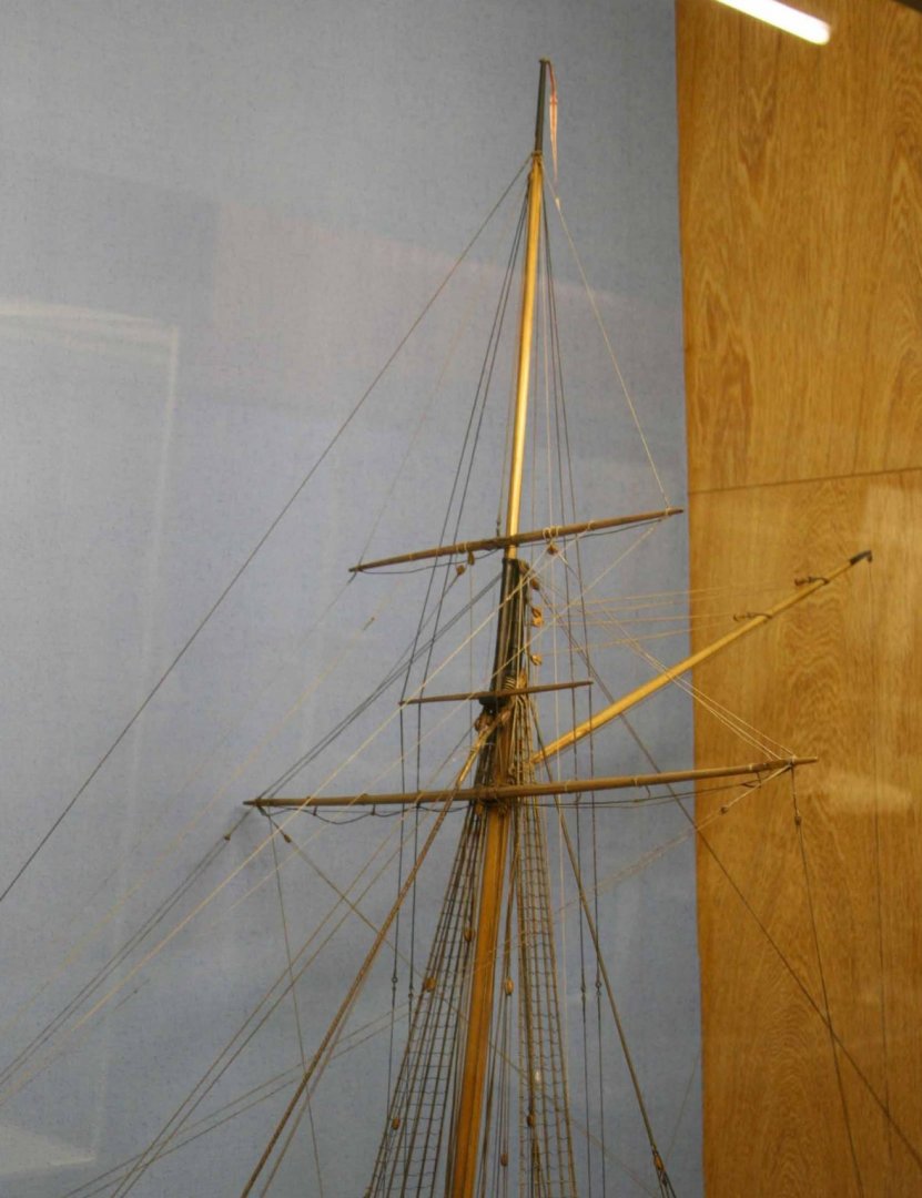
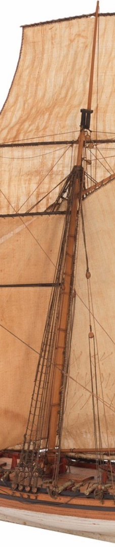
Post 69 A slight diversion to consider horses (or Footropes as they are commonly called) The kit does not indicate the fitting of Footropes to any of the yards. The Alert book indicates them only for the Topsail Yard. Hawke Model The Hawke model doesn’t show any. Alert Model by Roger Cole Roger Cole omitted them from his model. Irving Kingman doesn’t refer to them, but I can’t see from the limited photo’s whether any are fitted. Science Museum Model circa 1785 The Science Museum model of a later rigged cutter shows them, but by this time with the Topmast forward and the Square yard out of fashion, it makes more sense. This is just the latest of the rigging conundrums associated with this cutter build. The Spread-sail yard does not carry a sail in this configuration so footropes would be unnecessary. They are rarely seen on the Cro’jack yards of square riggers for the same reason. I would think that the Square-sail yard may well have been set up from the deck, raised and lowered as necessary on the horse. The Topsail Yard is probably the most likely for the fitting of footropes, but why so many models without them? The T’ gallant yard is a fairly small affair, each yard arm only a scale 15’. Would this be fitted with horses, again I don’t know, but I lean towards leaving them off. 0339 The yards are now all raised, albeit swinging around on their tye tackles. Despite the forgoing thoughts about footropes I can’t quite dismiss from my mind that there’s something missing from the set of yards. 🤔 B.E. 12/02/2020

- 335 replies
-
- 15
-
-
- alert
- vanguard models
- (and 1 more)
-
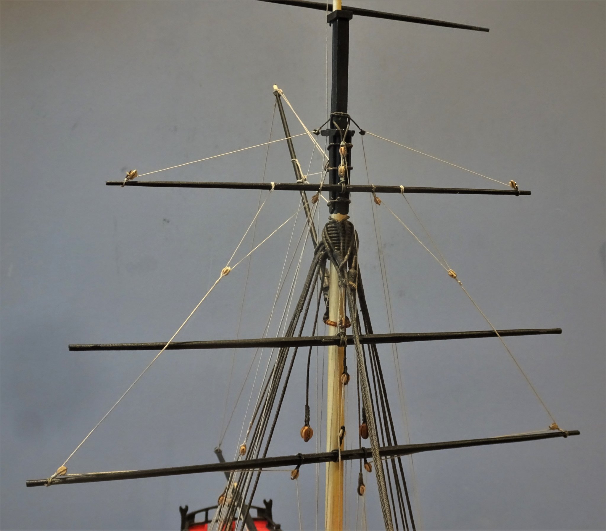
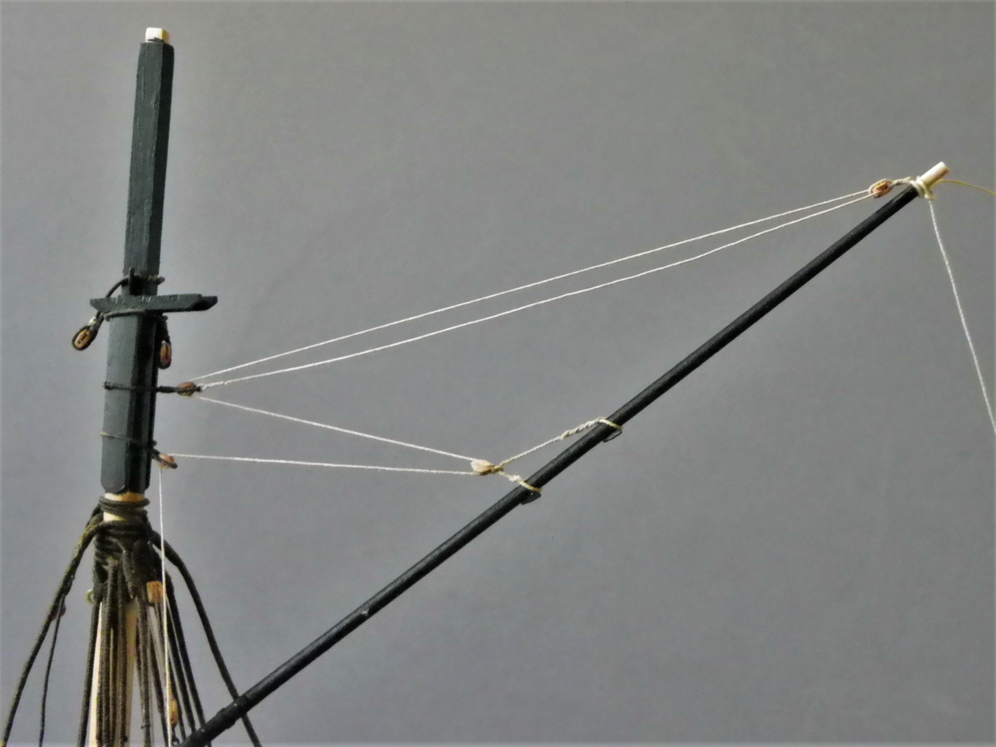
Post 68 A Horse for the Square-sail yard. I first considered the horse back in post 51, but now I need to fix the attachment point towards the top of the mast. Steel lists a ‘horse down the mast’ associated with the Crossjack yard (which for our purposes is the Square-sail Yard.) For the method of fixing I am following the narrative and drawings contained in Eighteenth Century Rigs and rigging by Marquardt. Figure 88 in the book shows the set up on a cutter mast pre 1800. The Horse has an eye splice at the upper end lashed to masthead. 0313 My interpretation is to use an eyebolt at the masthead to which the horse will be attached. The Lower end is set up with deadeyes and lanyard to an eyebolt in the deck forward of the mast. 0311 The deadeye set up afore the mast, I used 3mm deadeyes, and 0.63mm ø Syren line to represent the 5” circ Horse and 7” deadeyes. Model of Surly 1806 Altho’ a later period, a horse is still shown altho’ by this time it probably carried the Spread-sail yard, as the Square-sail yard had had mostly been dispensed with. At this point I can now play around with the Square-sail yard. The central yard tye block is required and an aft facing thimble thro’ which the horse will run. 0320(2) Iron thimble attached to Square-sail yard. With the tye block attached the yard can be raised on the horse. 0327 Raising the yard on the horse. 0326 0330 The Square-sail yard is hoisted over and above the Spread-sail yard on the horse. B.E. 10/02/2020


.thumb.JPG.356de66b759748e00dc29b96c3a1e8af.JPG)


- 335 replies
-
- 17
-
-
- alert
- vanguard models
- (and 1 more)
-
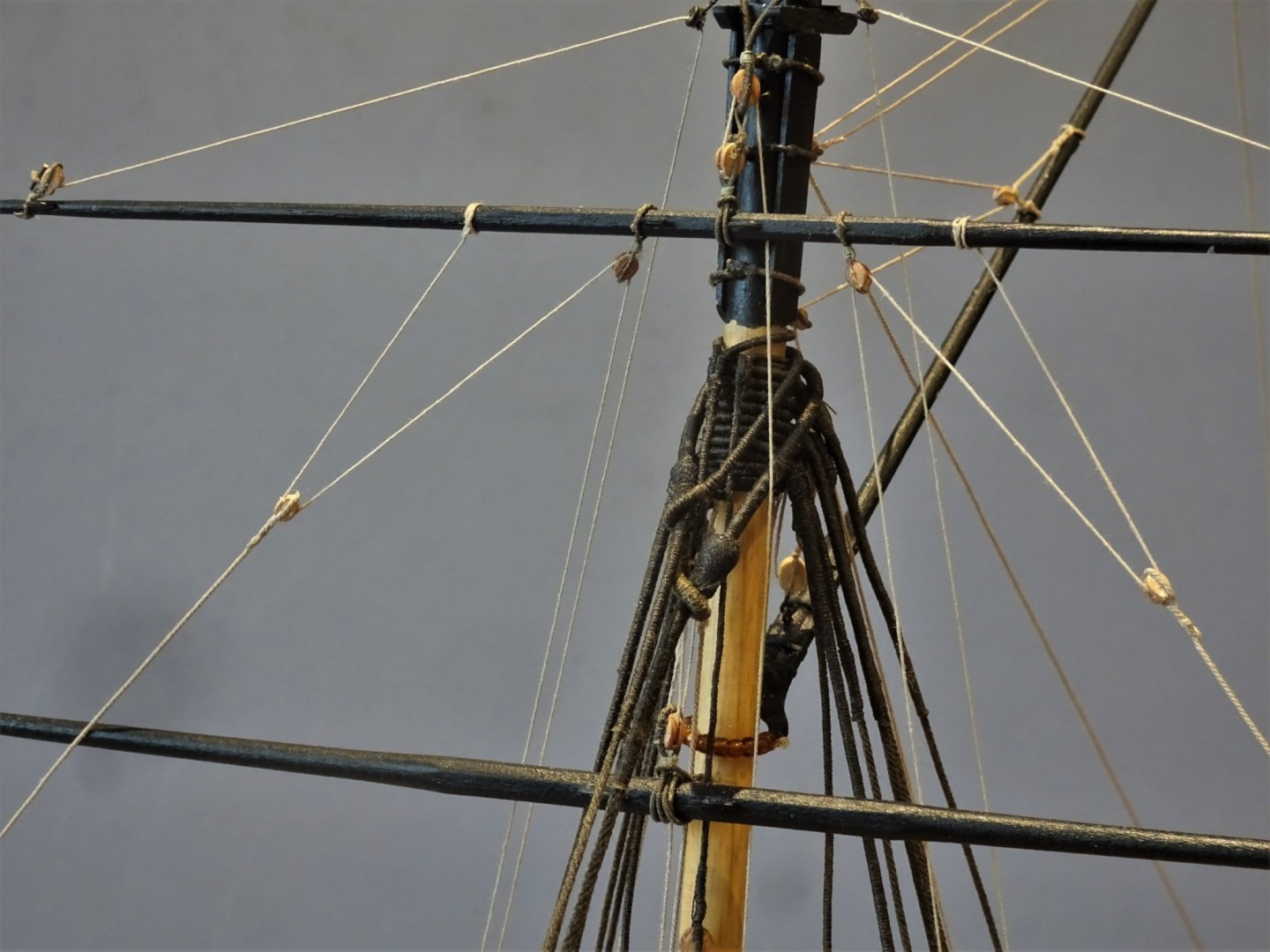
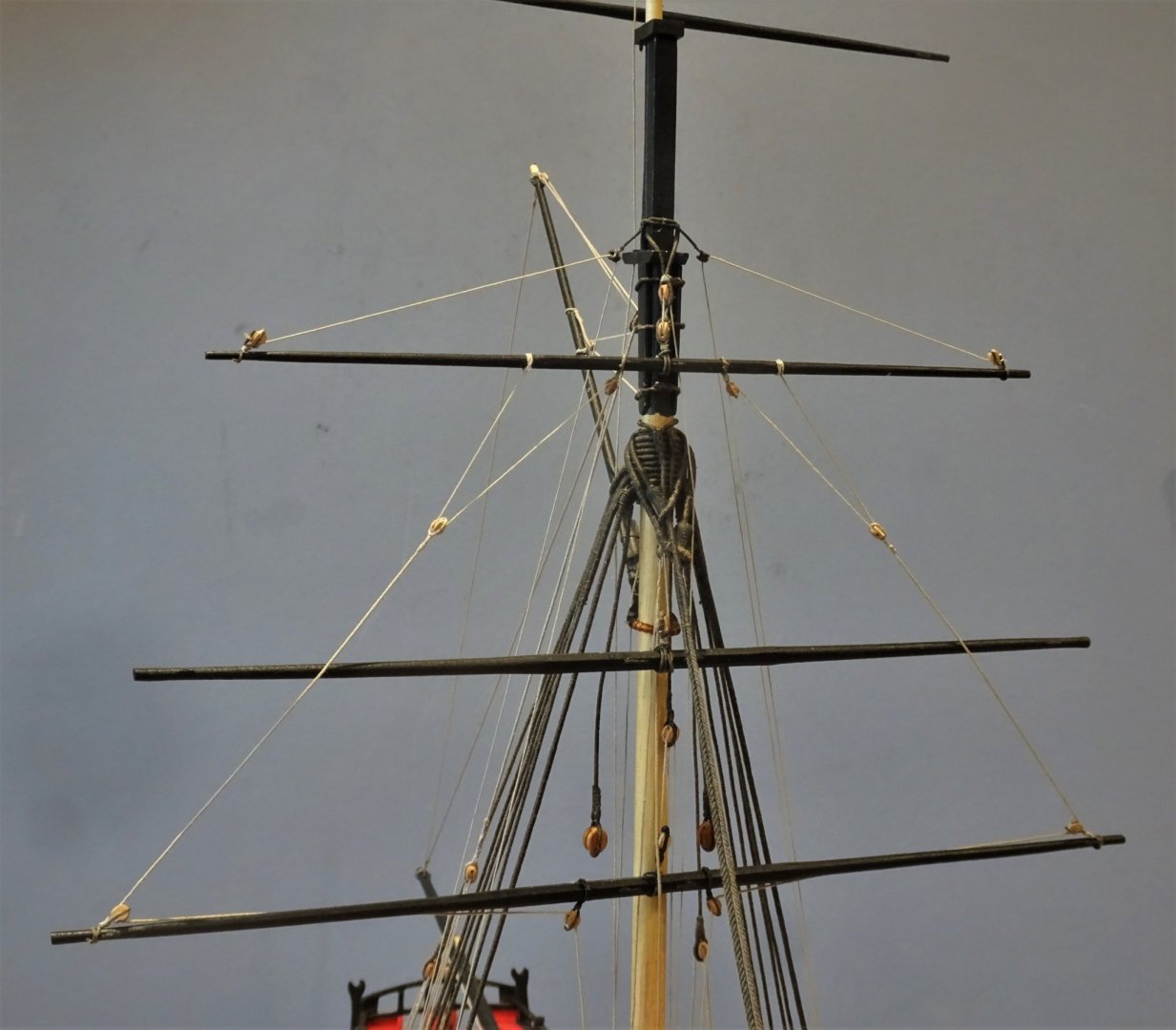
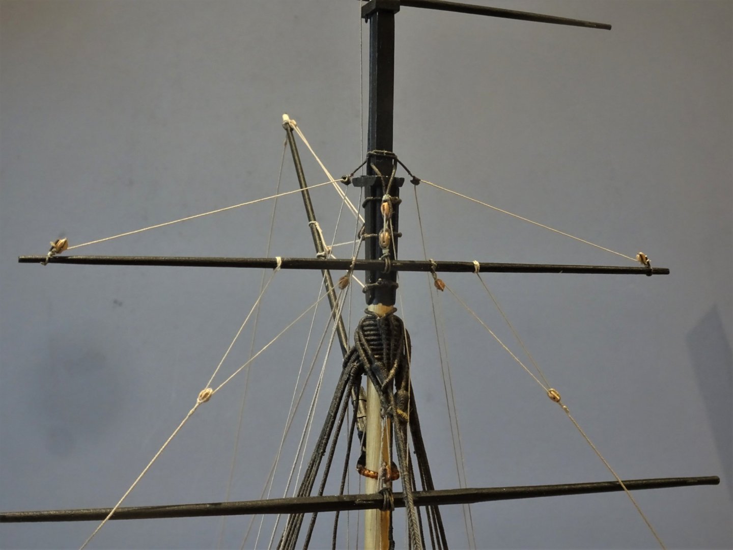
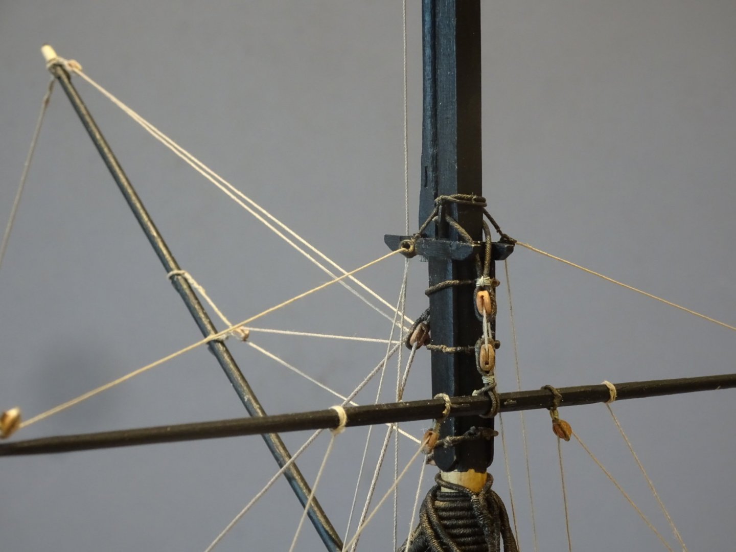
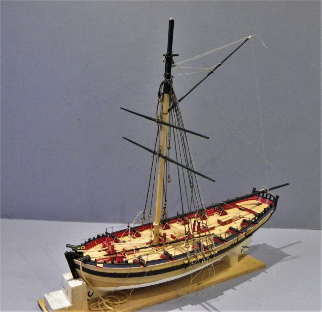
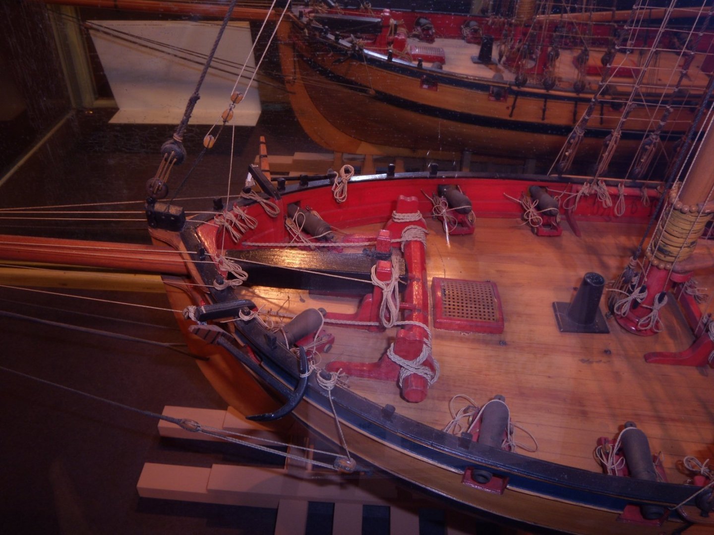
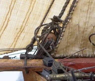
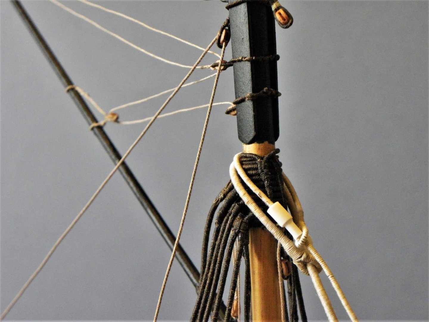
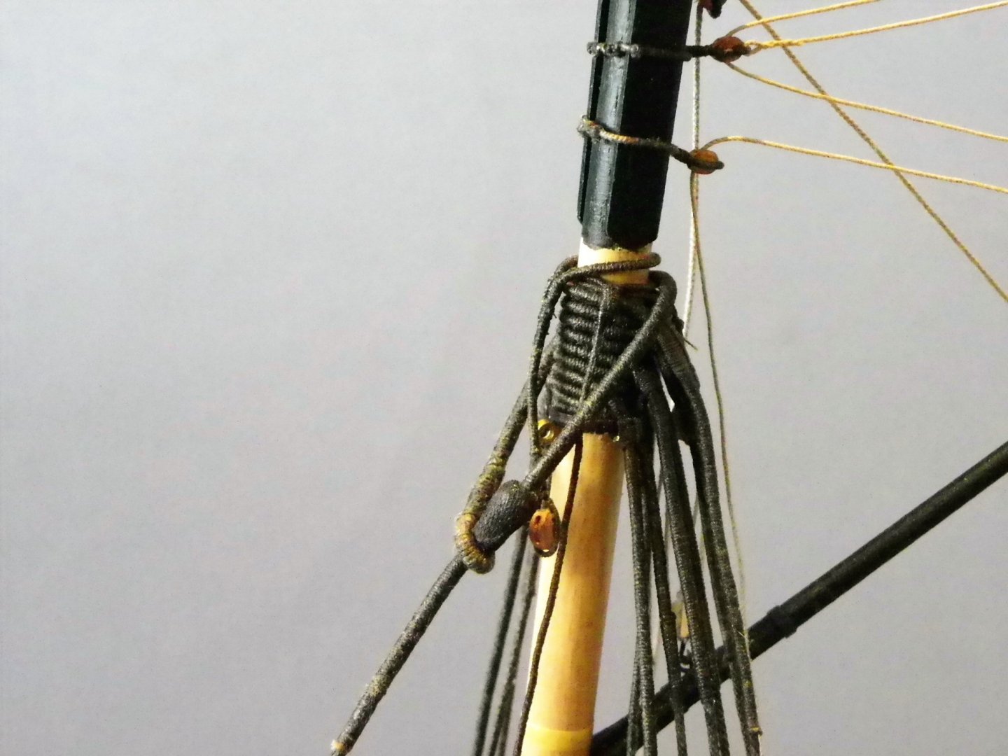
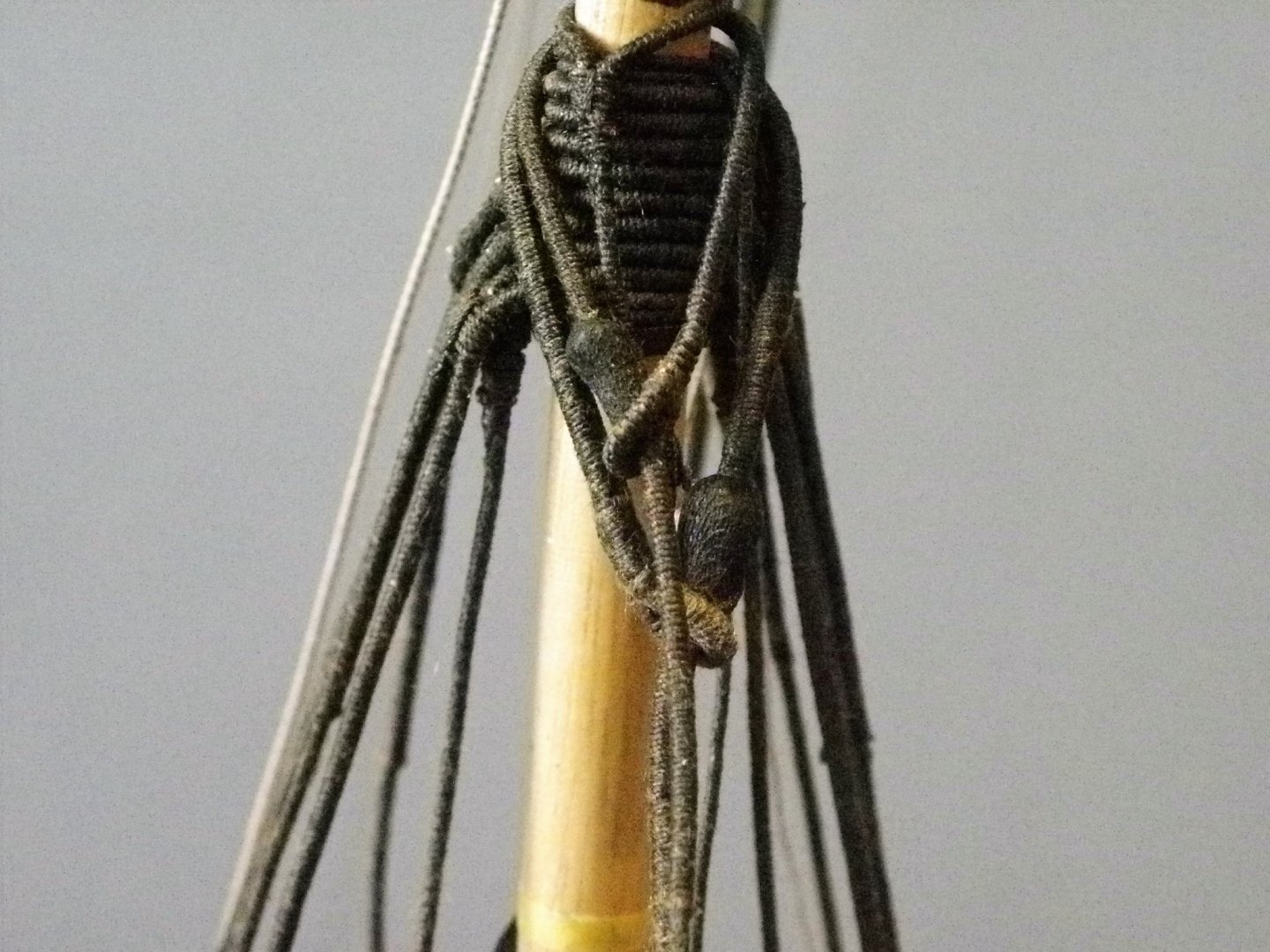
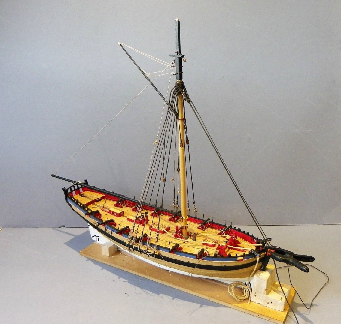
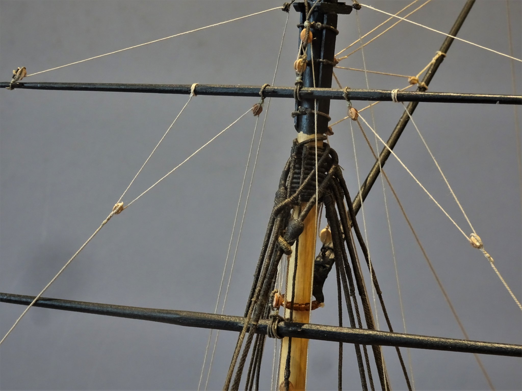
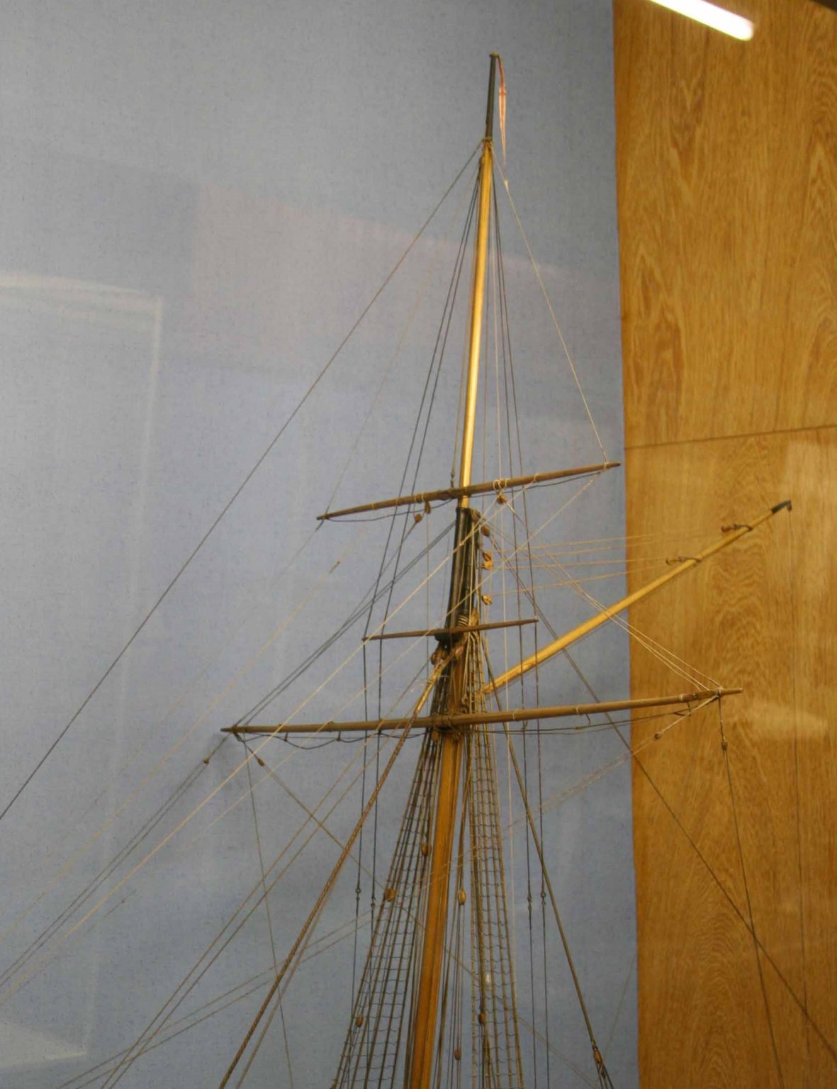
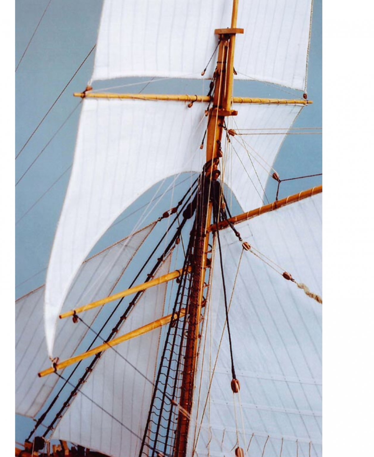
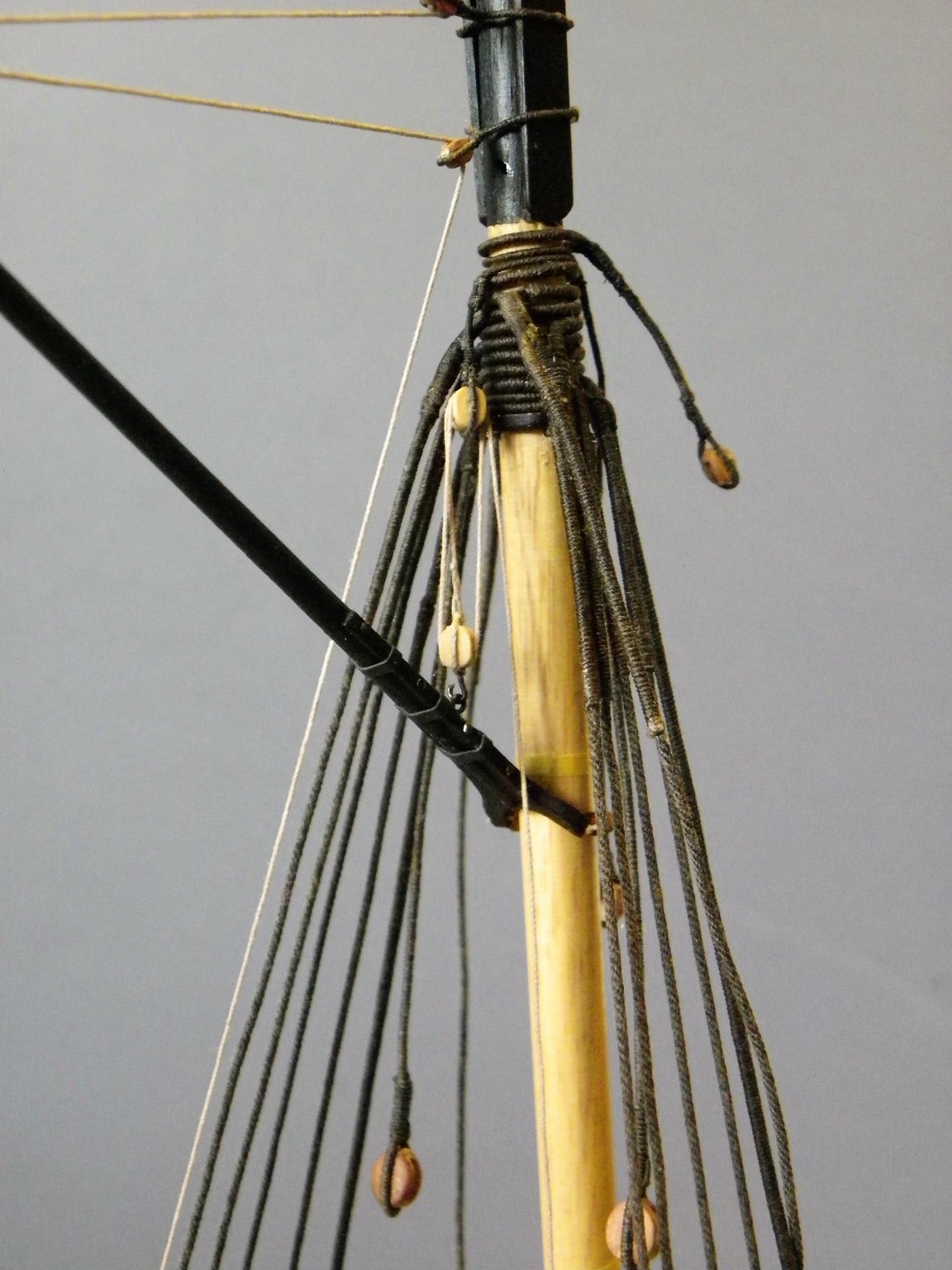
Post 67 Thinking about securing the yards. Everything I’ve read about cutters of this period suggests that the yards were not secured to the mast by use of parrels or truss pendents, which presents the modeller with a real problem as the yards will need to be secured if only temporarily to get the rigging in place. The kit gets around the problem by the simple expediency of having a parrel or truss on every yard and gluing and pinning the yards to the mast. I have been here before, albeit back in the 1980s with my first cutter build. 0307(2) 0304(3) A later spec cutter but even so no trusses, parrels, or pins were used in the building of this model. 0305 I wish I could remember how I approached this job, but it long preceded such things as ship modelling forums. 0303(2) The yards are however perfectly secured in position by a combination of the braces and Bowlines. Hawke model mast detail I cannot detect any sign of a truss or parrel on the Hawke model. I am starting with rigging the Spread-sail yard, but before I can even consider raising the yard the tackle blocks need to be attached, starting with the yard Tye block. 0309 This is a tricky little beggar, a 4mm single block with a served stropping formed into a ring that fits around the centre of the yard. It is by trial and error that the size of the stropping ring is determined using unserved thread to confirm the size. Two other blocks need to be attached at this stage; the Topsail sheet fall blocks, hanging below the yard just outside the slings. 0312 Raising the Spread-sail yard. 0314 I need to have this yard in place so that I can consider the practicalities of raising the Square-sail yard on a horse afore it. B.E. 09/02/2020
.thumb.JPG.efed4a4d6b646207927a3ffefa690eb5.JPG)
.thumb.JPG.99039a2fa2e222e03a5a5093a4ceb962.JPG)
.thumb.JPG.64e462c12304ff49ace445163e562d1a.JPG)
- 335 replies
-
- 20
-
-
- alert
- vanguard models
- (and 1 more)
-
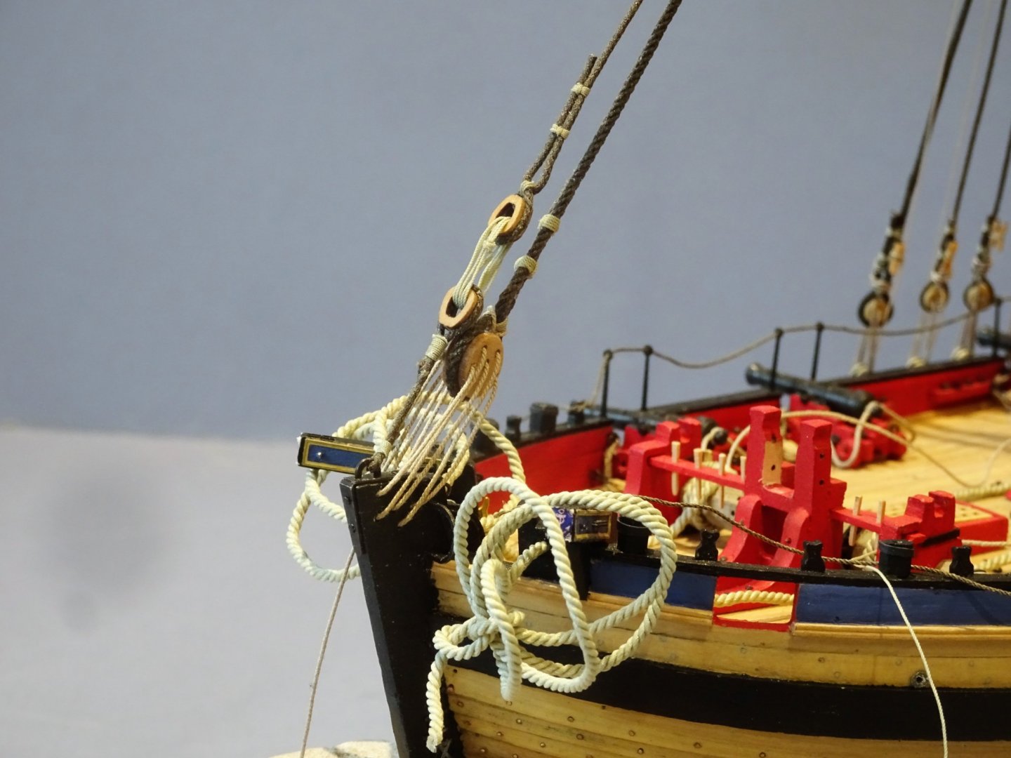
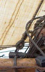
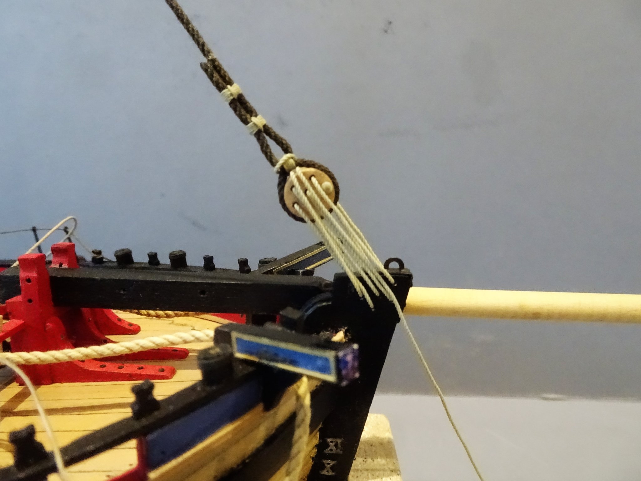
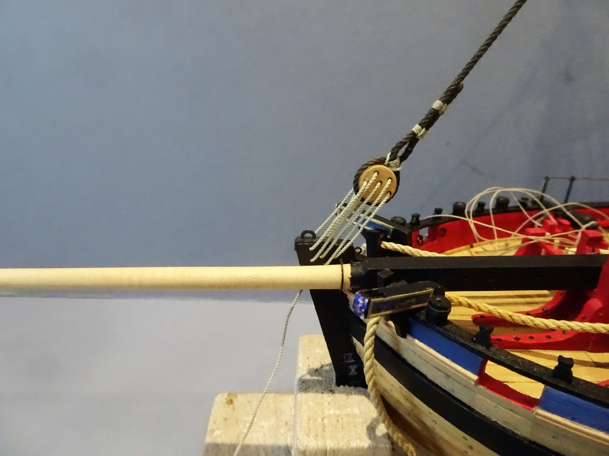
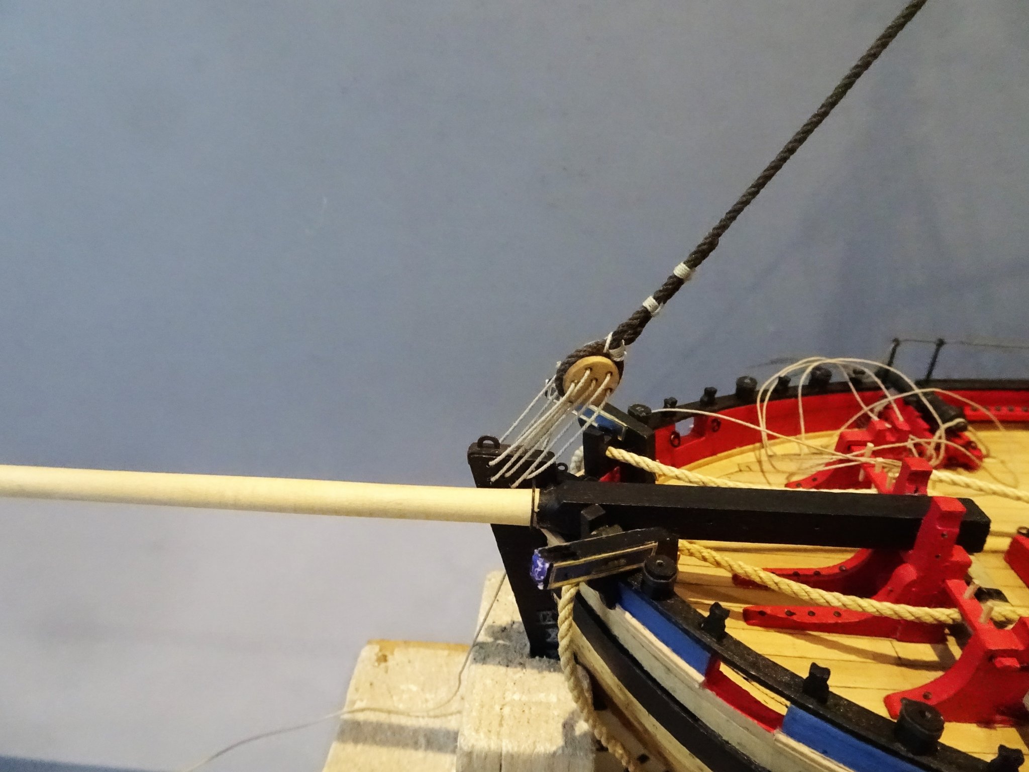
Post 66 Preventer Stay (Part Three) – lower end attachment. For the Preventer Stay Steel indicates 9” deadeyes and 3” circ lanyards. (0.4mm ø at scale) THE PREVENTER-STAY sets up with a laniard, reeved through the holes in the dead-eye in the lower end of the stay, and another dead-eye in an iron-bound-strap, bolted on the fore part of the stem. I was surprised to see Steel referring to deadeyes for the Preventer stay in his 1794 work, as all the cutters I have seen either have hearts or thimbles. The Alert book shows hearts, and the Kit instructions a thimble and lanyard arrangement hooked onto the stem. Hawke model The Hawke model shows the stay secured to a single thimble strapped to the stem. Not least because I happen to have them, I have opted for Chuck’s closed hearts, but also hearts had been widely used for stays on ships of this period. 0297 5mm Syren Hearts, spot on. 0298 For the Lanyard I have attached some 0.4mm Morope. Can’t get them to look completely right until they are pulled taut and seized. 0299 The lanyards won’t be tied off until the Bowsprit has been fitted and the yards raised. 0296 Moving on to that tricky business of yards. B.E. 06/02/2020


- 335 replies
-
- 18
-
-
- alert
- vanguard models
- (and 1 more)
-
Thanks for the insight Frank. 👍 Hi Derek, making my own rope has never really interested me, particularly now you can get such nicely made stuff. Same with fittings, I only make things where I can't get a good quality fitting such as supplied by Chuck. Thanks Dirk. 🙂 B.E.
- 335 replies
-
- 1
-
-
- alert
- vanguard models
- (and 1 more)
-
Hawke doesn't look as clean as that Dirk 😉. I have a strong leaning towards the Morope for this particular lanyard, what size line did you use? B.E.
-
Cheers, Rusty👍 Post 65 Main-Stay (Part Two) – lower end attachment. The Mainstay at its lower end is attached to the stem using a large five-hole deadeye. In the kit this is provided by a three- part self-assembly wooden version. 0256(2) I would suggest that a simple jig using steel pins is made to ensure hole alignment during assembly. It would have been nice to have this deadeye made in a nice wood, Box or perhaps Pearwood, but it hasn’t come up too badly with a coat of wipe-on. I was tempted to use the very nice Boxwood version produced by Chuck for the Cheerful model, but it was just a tad too large. In setting up the Mainstay, this is how Steel describes it. THE STAY Sets up with a dead-eye, turned into the lower end of the stay with a running or Flemish-eye, and with a laniard, reeved through the holes in the dead-eye, and through holes bored through the head of the stem. This looks like the arrangement shown in the Alert Book. The kit instructions show a simple seizing. The Hawke model Not particularly clear but there seems to be throat seizing atop the deadeye with the running end loosely taken around the stay and presumably seized again. The Science Museum model shows the usual deadeye stropping arrangement with a throat seizing and with the running end seized to the stay. I note that Chuck has also opted for this arrangement on his Cheerful model. I also opted for the arrangement as shown above, if nothing else the seizing is an easier job than forming an eye and seizing to the deadeye strop. Lanyards. Steel lists a 4” circ line for the deadeye lanyards which scales to 0.5mm ø line. The kit indicates a 0.25mm line which does look a little thin for this jumbo deadeye. I tried two options to check what suited my eye best. 4435 4436 Lanyards rigged with Morope 0.6mm line Morope is very fine line with great definition to show off this prominent feature of the cutter rigging. 04444 04442 Lanyards rigged with Syren 0.45mm line Syren is excellent natural fibre line but it doesn’t have quite the pure definition of the Morope but is perhaps a little more in scale. Syren. Morope, Morope, Syren, decisions, decisions, I used to be decisive but now I’m not so sure. When it comes to rigging the lanyard the kit arrangement is straightforward, but it seems a bit odd to me that the standing end is secured by a knot at the stem rather than the deadeye. I have opted for an alternative method whereby the lanyard is knotted at the deadeye in the usual way and having passed thro’ the sequence of deadeye and stem holes and will be hitched around the stay and seized to the standing end of the lanyard. At this point I thought I would test fit the Bowsprit to check that there was no fouling of the Mainstay lanyard, fortunately not, but I did have a panic moment thinking whether the Bowsprit would fit thro’ from aft given that I hadn’t checked it since fitting all the deck clutter. Part three will cover the Preventer stay attachment. B.E. 05/02/2020


a.jpg.5a763ee9908f127bbdfca68f9178f93e.jpg)
.thumb.JPG.1e0737b51e667f593c20a79088e4fd5b.JPG)
- 335 replies
-
- 14
-
-
- alert
- vanguard models
- (and 1 more)
-
Good job I put them on opposite sides then Frankie. 😉 B.E.
- 335 replies
-
- 2
-
-
- alert
- vanguard models
- (and 1 more)
-
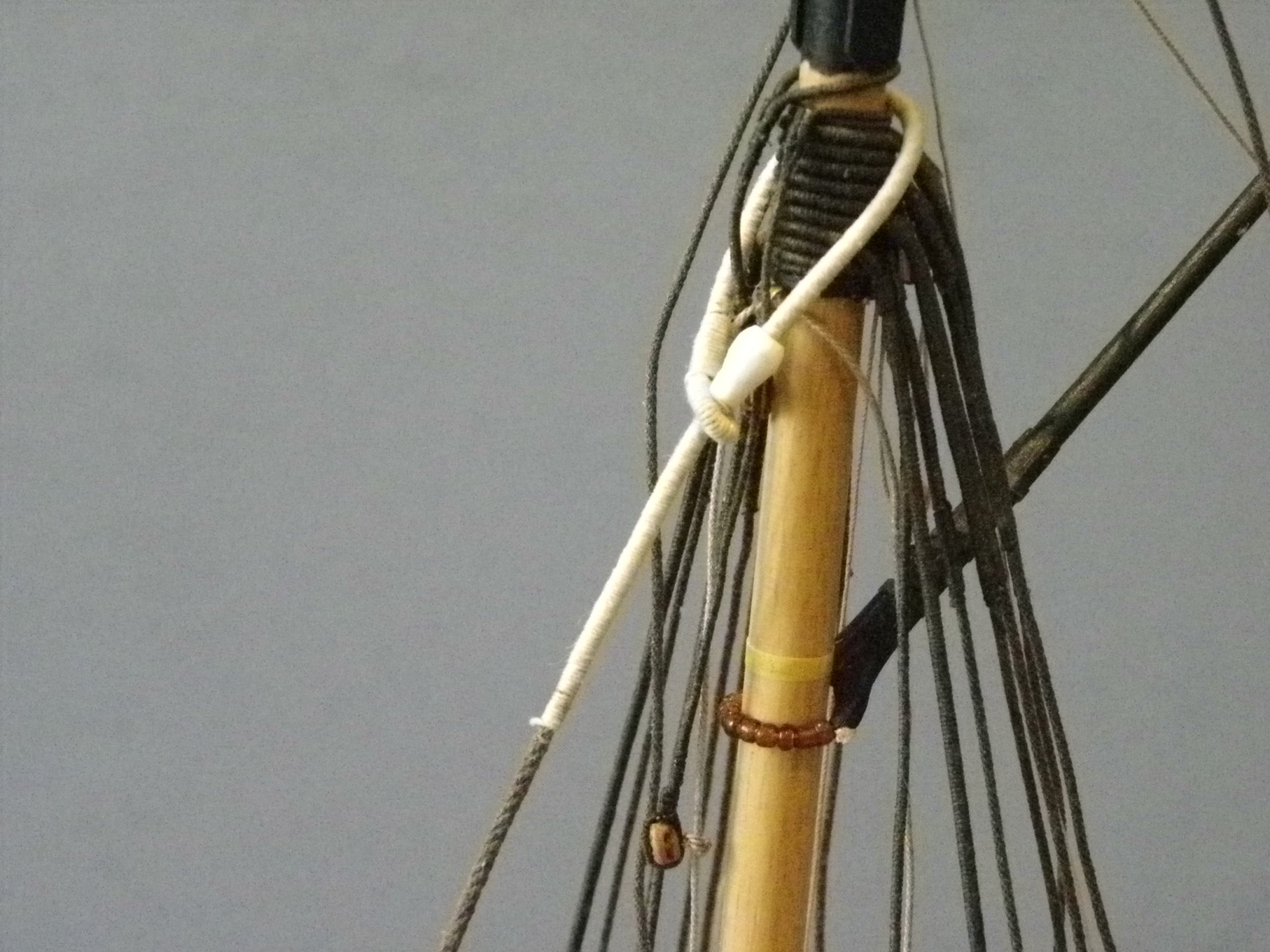
Post 64 Mainstay and Preventer stays (Part One) The kit uses 1mm and 0.75mm diameter line for the stays and has a simplified attachment around the masthead. The line equates to an 8” circ line for the Mainstay and 6” for the Preventer stay. This seems somewhat under-weight, even the much smaller Sherbourne has respectively 9” and 5” cables indicated. Steel indicates a 13” circ Mainstay and a 6½” circ Preventer Stay for a 200-ton cutter. This equates at scale to 1.64mm ø and 0.82mm. ø A 1.6mm ø line looked too heavy at scale to my eye, particularly when serving is added, so I opted for Syren 1.37mm line for the Mainstay and 0.88mm for the Preventer. This was dyed and left under light tension until required. 0259(2) To give a more authentic look the stays should be served around the masthead and along the stay for some six feet below the mouse, used to prevent the collar of the stays tightening around the masthead. I served the Mainstay with the kit provided 0.1mm line. Mouses Mouse - Main Stay L = 1/3 circ of stay = 3.96mm ø = 3 x ø of stay =4mm To make the Mouse for the Main Stay I used styrene tubing; a length of 3.2mm ø tubing inserted inside a length of 4mm ø tubing. This gives me the required external diameter whilst having an internal hole that fits the served stay. 0250 Testing the mouse fit on the stay collar. In reality mouses were woven onto a stay, but as model makers we mostly use a solid core covered in line. Ladies tights material is perfect for replicating the weave look particularly at smaller scales, but don’t get caught rummaging thro’ her underwear drawer. 2395 The weave treatment is applied 0266(2) A completed Mouse. 0280 Main Stay in place Mouse - Preventer Stay The Mouse is simply a smaller version of the Main Stay mouse. L =1/3 circ of stay = 2.77mm ø = 3 x ø of stay =2.64mm For this smaller mouse I used 2.3mm ø tubing inserted inside 3.2mm ø tubing. 0253 The Preventer Stay Mouse before shaping. 0291(2) Preventer stay mouse in place. 0288 I opted to place the mouses Mainstay (port), Preventer stay (Starboard) 0292 Part Two will cover the lower end attachments. B.E. 04/02/2020

.thumb.JPG.a0dd366bb16d5749bcf9e23246f8c6f3.JPG)
.JPG.f45f82a77014473753bbcba58e982161.JPG)
.thumb.JPG.a188324c849000ce9e7e5a80dcb60da8.JPG)
- 335 replies
-
- 22
-
-
- alert
- vanguard models
- (and 1 more)
-
Needed or not, I agree they do add something to the build sitting atop the boom jaws, but that's for later, at the moment I am fully engaged in a mousing exercise.😉 B.E.
- 335 replies
-
- 1
-
-
- alert
- vanguard models
- (and 1 more)
-
Correct flag
Blue Ensign replied to MESSIS's topic in Discussion for a Ship's Deck Furniture, Guns, boats and other Fittings
At the time of the Royal Caroline the Red Ensign represented the senior squadron of the Royal Navy, so I would suggest that it is perfectly reasonable for this vessel to wear it. I doubt Cleveley was wrong. In order of seniority the Red Squadron was followed by the White Squadron and then the Blue. An Admiral of the Red was senior to an Admiral of the White, who in turn was senior to an Admiral of the Blue. ps Good choice of Ensign Spyglass 😉 B.E. -
The kit does provide them Dirk, albeit in etched brass form, which doesn't really appeal to me. I may well retro fit a few, and I have a cunning plan to use the bored out centres of the mast rings provided in the Cheerful kit, just the right size, but they will need to be cut and re-joined. ps; in the kit instructions Chris has commented that they need not be added to a model without sails. Regards, B.E.
-
Post 63 Completing the masthead blocks and raising the Gaff. Standing blocks are required for the Boom topping lift and the Gaff Halyards. 0229(2) These are stropped with served line using a 4mm block for the boom topping lift and 3mm blocks for the Gaff Peak halyards. (The kit has them stropped to eyebolts in the masthead) When it comes to the how and where elements of rigging the gaff and boom tackle things get a little more confusing. Gaff 4421 Raising the Gaff. The Gaff Throat Halyard or Gaff jeer tackle, as it is referred to in the Alert book is set up with the standing block secured around the masthead, with the tackle hooked to an eyebolt atop the gaff jaws, the fall being secured at the bitts. (behind the mast) The kit instructions also show the fall secured to the bitts. Steel calls this the inner tye, but describes a completely different set up. INNER-TYE is similar to the outer tye, and hooks to an eye-bolt in the jaws of the gaff; then reeves through the lower iron-bound-block, that hooks to an eye-bolt in the aftside of the mast-head, below the rigging. It has a double-block bent to the lower end, and sets up by the haliards;, the lower block hooking to an eye-bolt on the opposite side to the other tye. The Cheerful rigging plan shows this secured to the pin rack on the Portside. I have opted to follow the Alert book /kit arrangement. 0228 Throat halyard tackle attached to the gaff. Peak Halyard The Alert book indicates that the Gaff peak halyard tackle block is secured to the Portside channel but doesn’t indicate further where the tackle fall is belayed. The kit shows the running end of the peak halyard belaying to the bitts without a tackle attached. Steel calls this the outer tye and indicates that the halyard block is hooked to an eyebolt in the deck close behind the mast. TYE, OR HALIARD, reeves through a block on the span, that clinches or splices round the middle of the gaff. The standing-part of the tye clinches round the mast-head, or hooks to an eyebolt in the mast-head: the other end reeves through a second iron-bound-block, hooked to an eyebolt in the mast-head, and at the lower end is the double-haliard-block, that does not splice as other haliards, but reeves through the strap, and makes fast with a hitch; and the remainder is expended in turns round the block and strap. The haliard-block connects by its fall to a single or double block, hooked to an eye-bolt in the deck, close behind the mast. The Cheerful rigging plan shows this without a standing end with the halyards belayed to both the Portside pin rack opposite the mast, and to a cleat on the mast. Cheerful did however post date Alert by some thirty years. I have opted to follow the Alert book arrangement with the tackle block hooked in the Portside channel the running end will be secured to a shroud cleat. This at least keeps the tackle away from the boom. 0221 Upper end of the Peak Halyards. 04424 Connecting the block to the peak halyard using a ‘false’ splice. 0219 Lower end of Peak halyards tackle hooked to the Portside channels. Boom Topping Lift The Alert book has the standing part clinched around the boom end, runs up thro’ the standing block at the masthead, with a single block seized into the fall which is positioned at a level just short of halfway down the mast. The tackle block is hooked to an eyebolt in the aft end of the starboard channel. The kit plan follows this arrangement with the running end secured to a cleat on the drift rail. Steel has a slightly more substantial arrangement: TOPPING-LIFT is taken upon the starboard-side, and reeved through the upper-block, hooked to an eye-bolt in the mast-head; then lead down and reeved through the block at the boom-end. The standing-part clinches round the mast-head, or hooks to the same eye-bolt; the leading-part comes down, and has a double-block spliced in, or turned, that connects by its fall to a single-block, and hooks to an eye-bolt in the after part of the channel, and belays to a pin in the shroud-rack. Sometimes it has the addition of a runner and sometimes rigged as the driver-boom in ships. I have opted to follow the Alert book /kit arrangement. Rigging the Topping Lift For the lift I am using Syren 0.6mm line with a 4mm single block spliced into the end. The tackle is 0.3mm line, spliced into the strop of the lift, with the tackle running thro’ a 4mm single block hooked to the starboard channel. This is slightly heavier tackle than shown on the kit plan. 0233 Topping Lift spliced around the boom end. 0234 Topping lift passing thro’ the masthead block. 0230 'Splicing' the block into the lift end. 0245 Tackle hooked to the Starboard channel. 0244(2) Run of the Topping Lift. 0232 Not in any hurry to secure these lines yet, snagging lines that have been tied off can present problems, and there are endless opportunities for this to happen. B.E. 02/02/2020


.thumb.JPG.703578e5761aff2deb465d9d807de961.JPG)

.thumb.JPG.87f884b25105f615eefa0fb4839cef33.JPG)

- 335 replies
-
- 21
-
-
- alert
- vanguard models
- (and 1 more)
-
You’re welcome stuglo, and thank you. B.E.
-
Cheers Guys, and thanks Don for looking in, glad you're finding the log of use.👍 B.E.
- 335 replies
-
- 2
-
-
- alert
- vanguard models
- (and 1 more)


.JPG.8c73cf34e775ca1bf243a4dc732eead7.JPG)
.JPG.ee68077d784be559a31260a5cabc1528.JPG)

.JPG.1b03205b4dd8d7fd02ac5da6eb0834c9.JPG)
.JPG.6a1e65e6ef87291db4ee19f08c85a1dd.JPG)


.JPG.dcbe4c567ac232808e00ad8c093dff0f.JPG)


.JPG.4fd5a89afe0e0528b8295237fd30e1a4.JPG)
.JPG.bc0a6dbc6fcaae7c93240308079b67ed.JPG)
.JPG.b5867d031cf0374b881eaa5782729e41.JPG)


.JPG.c7181c459912e700fe6cc945141262a4.JPG)
.JPG.9387c363bda8c1af29194b1614904e8f.JPG)
.JPG.36107d9acd0e25c8b803929a13f51b81.JPG)


.JPG.fdf95a439e995ceb7565713f85f08e80.JPG)

.JPG.92b24cdd40e53582311edd98be6e499b.JPG)