.JPG.ca33079f5815b861e67b9c2cccd37982.JPG)

Blue Ensign
-
Posts
4,569 -
Joined
-
Last visited
Content Type
Profiles
Forums
Gallery
Events
Everything posted by Blue Ensign
-
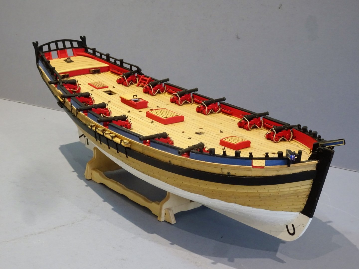
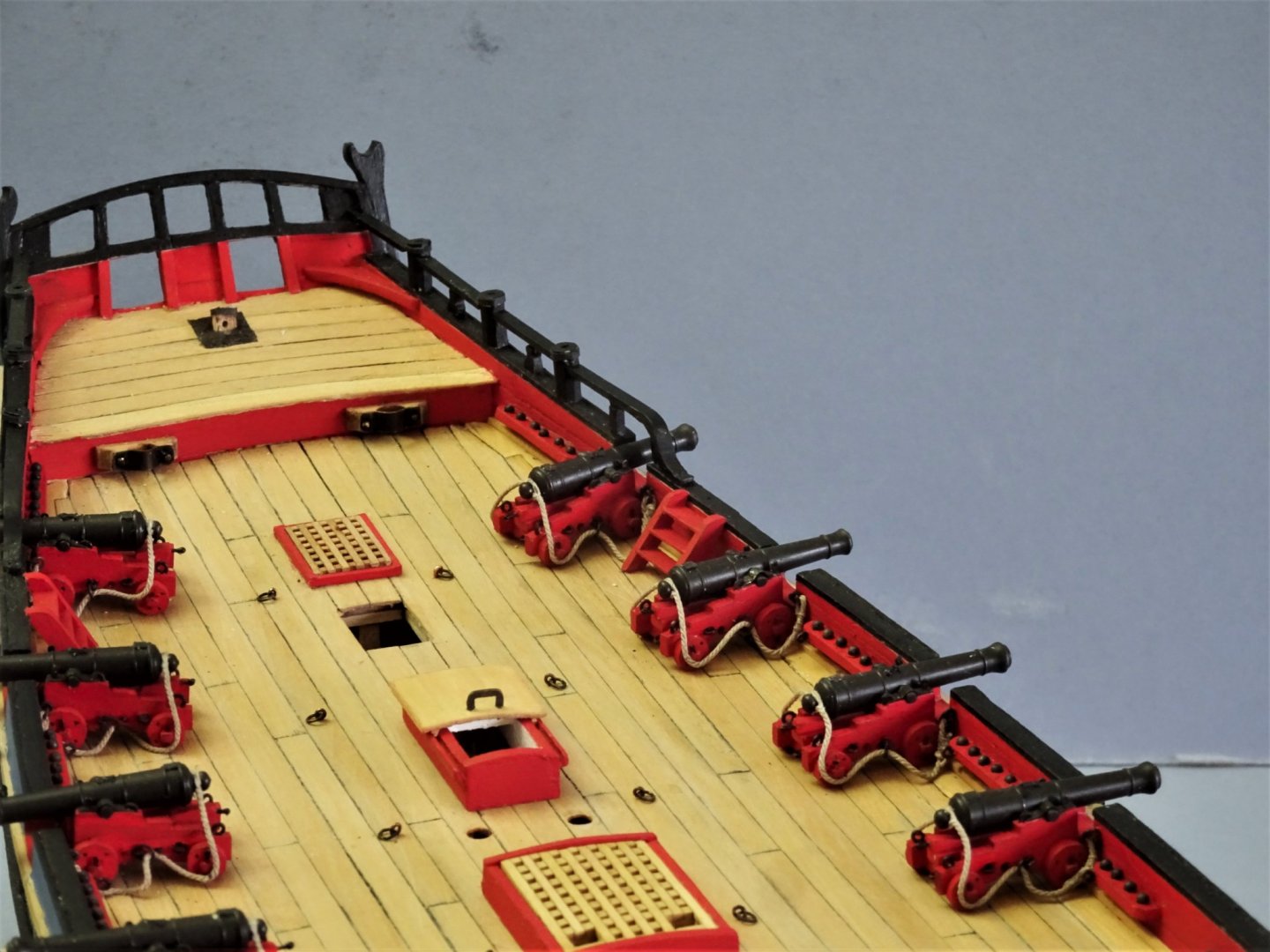
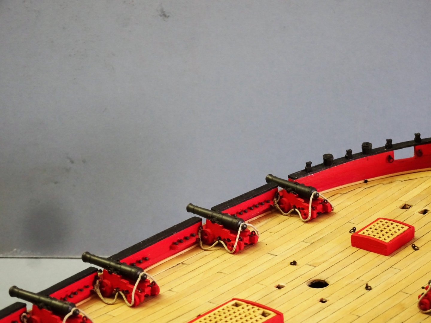
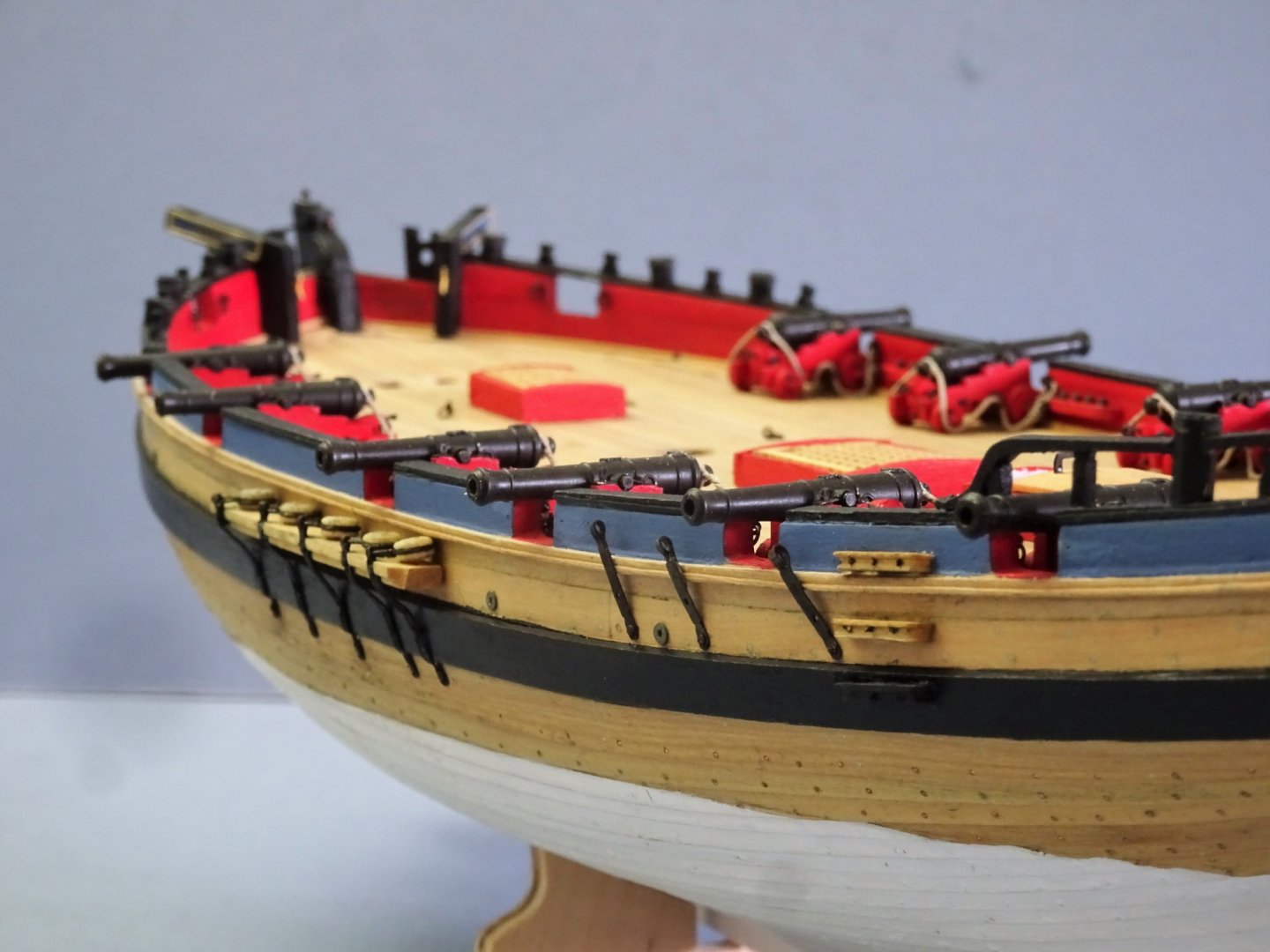
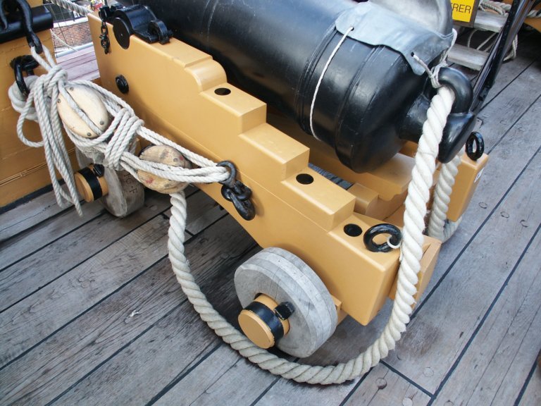
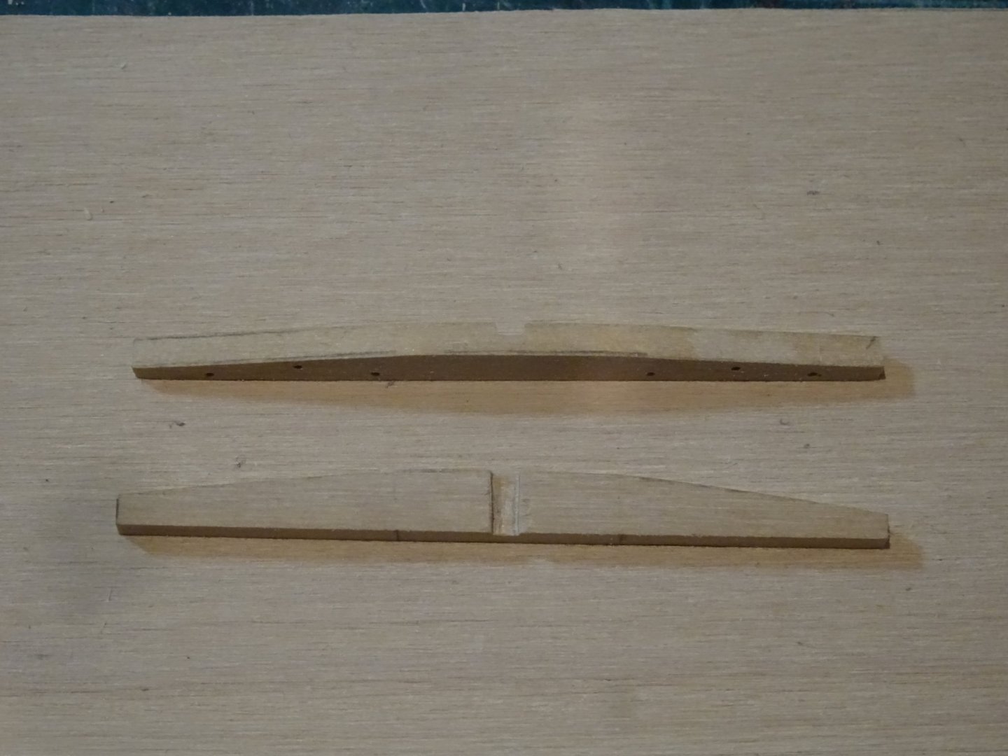
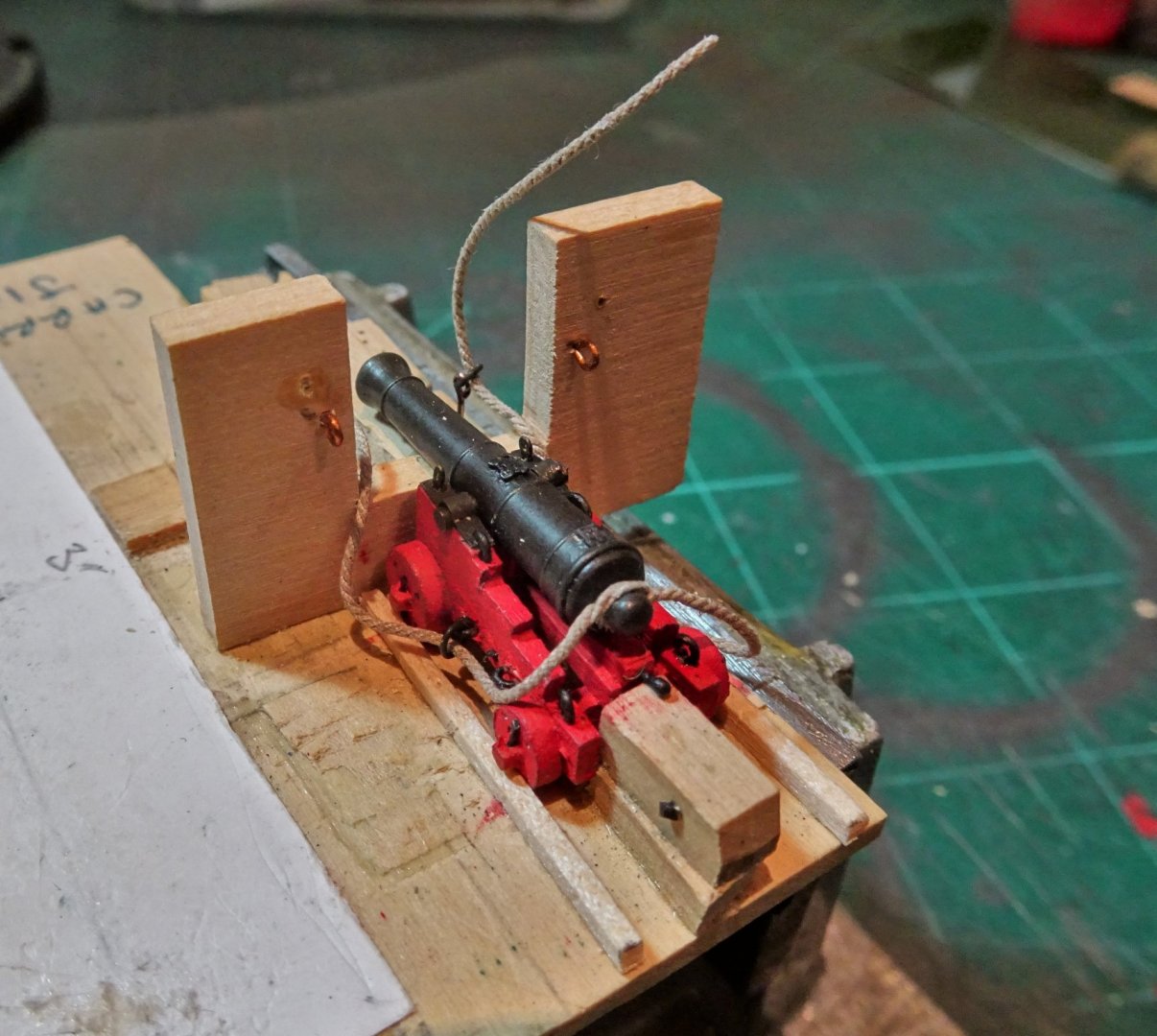
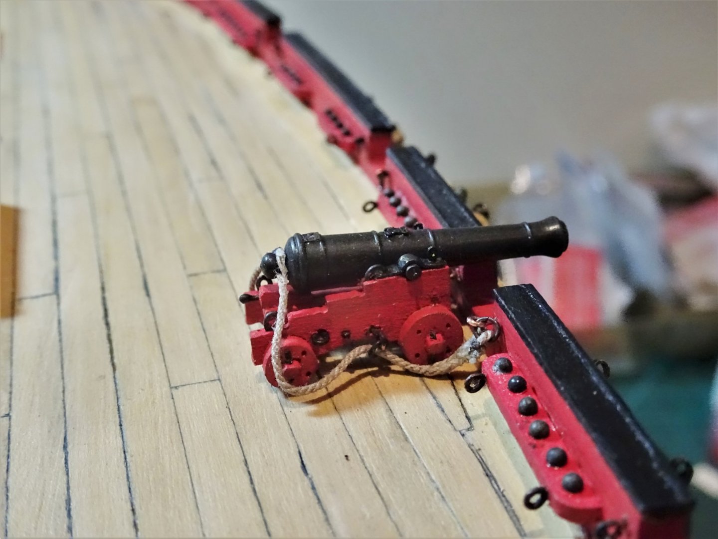
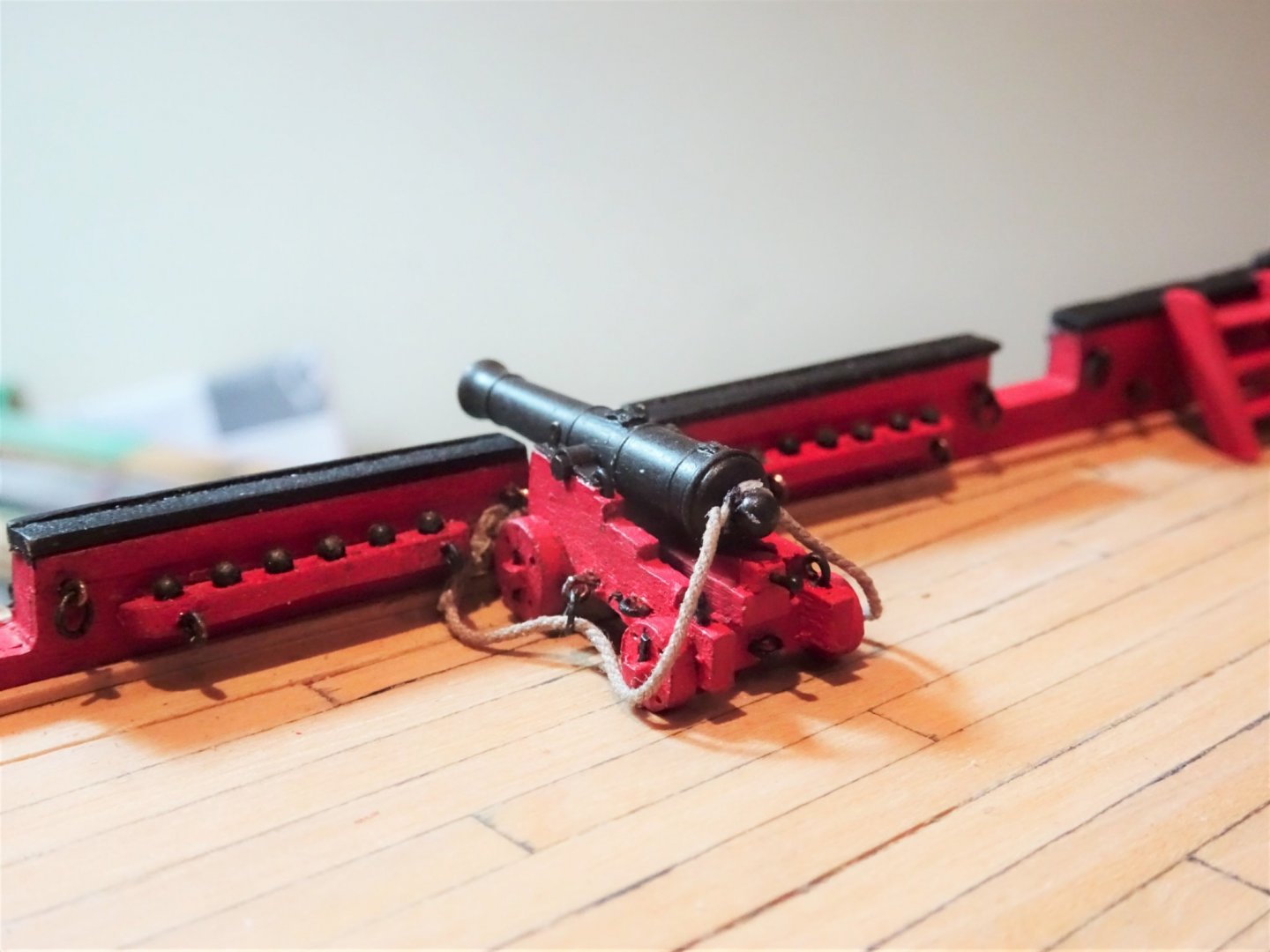
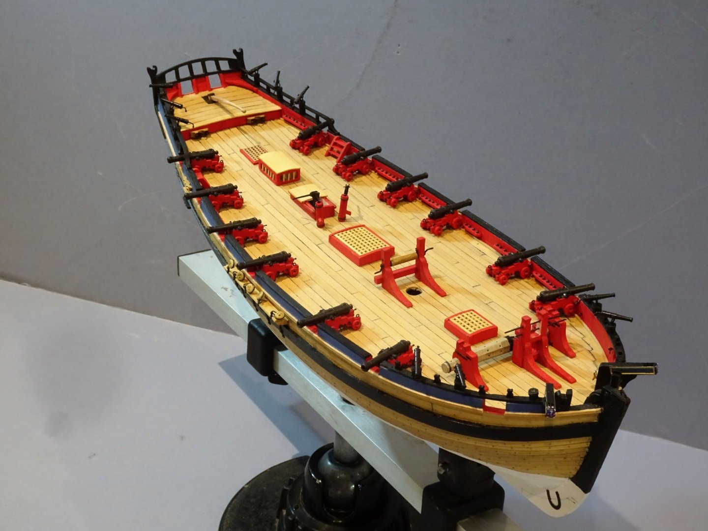
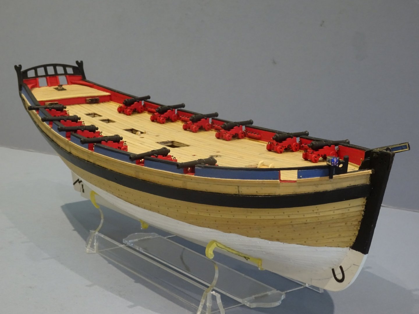
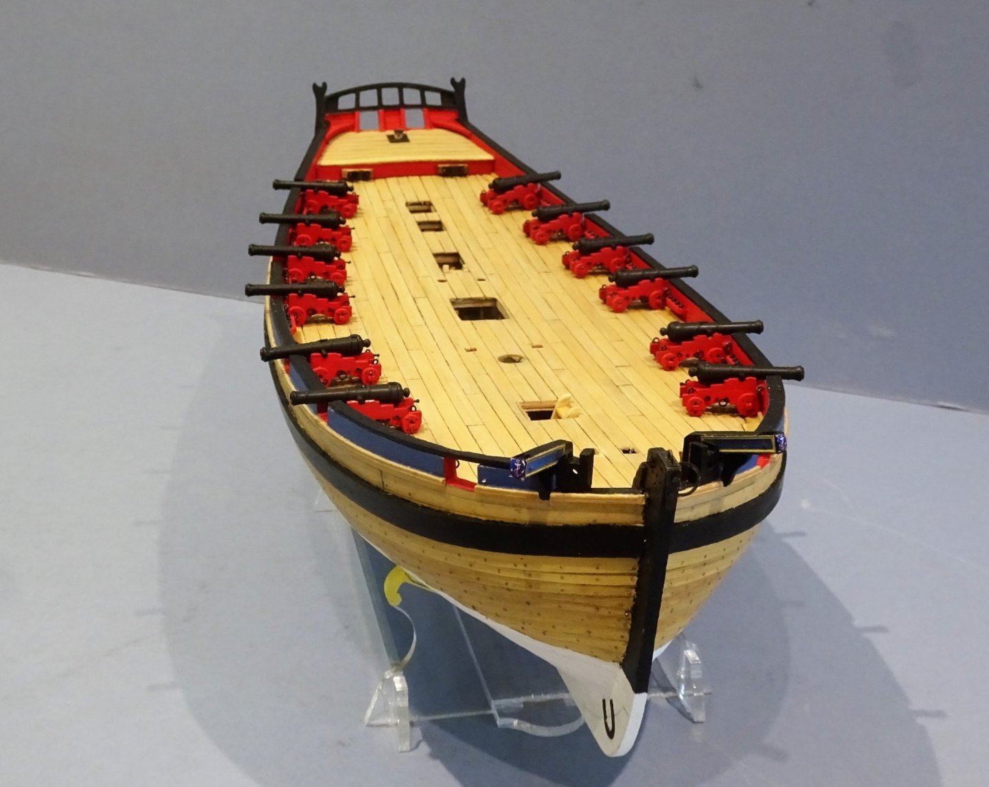
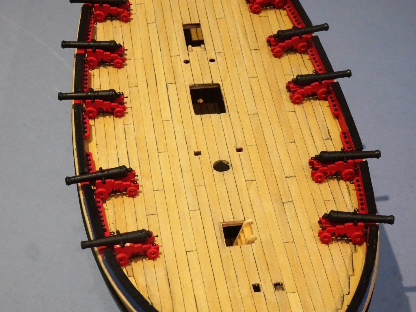
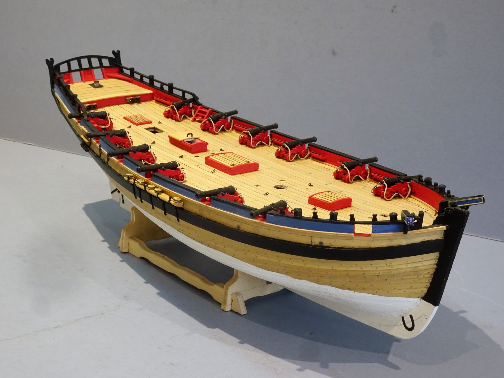
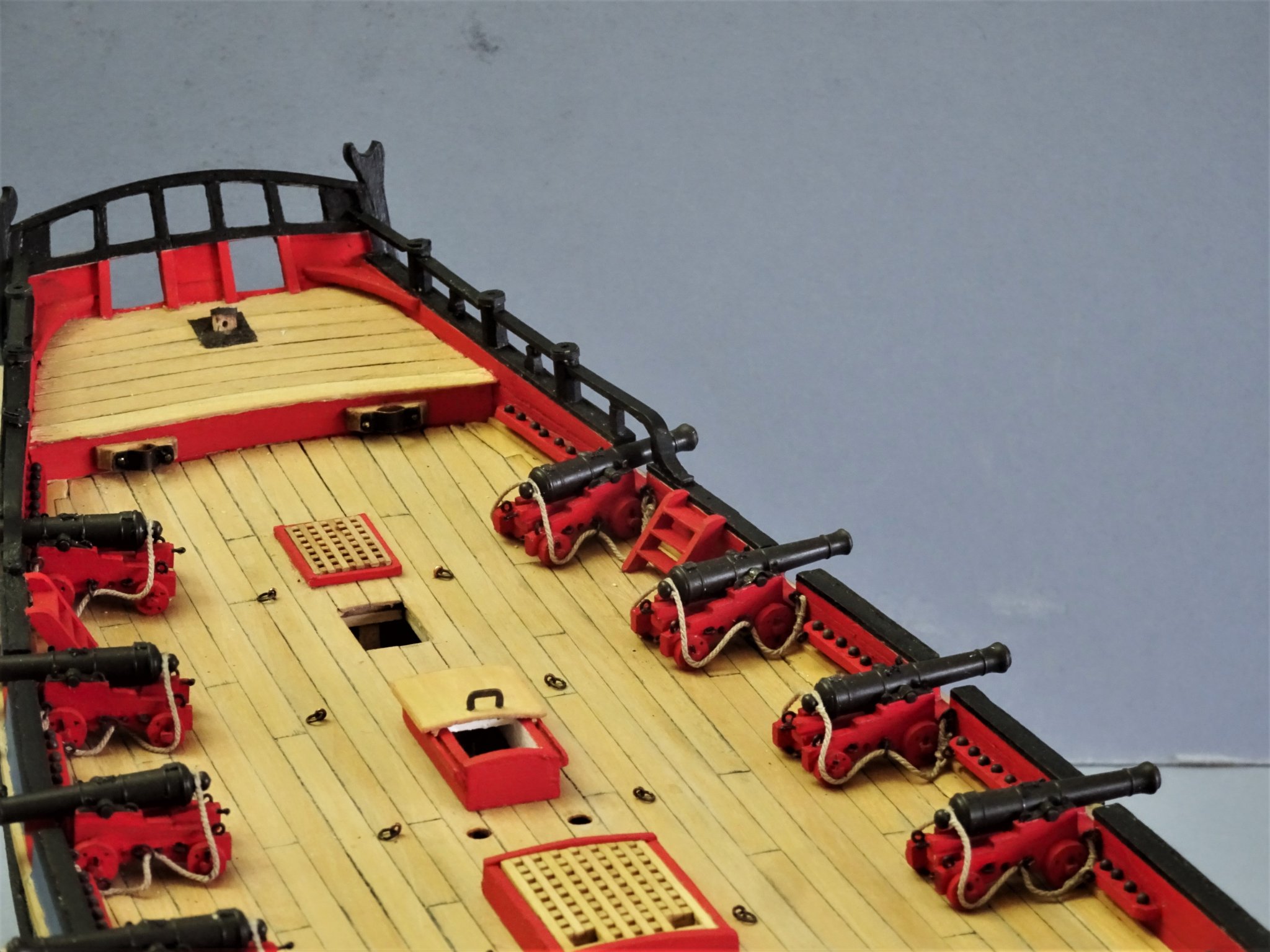
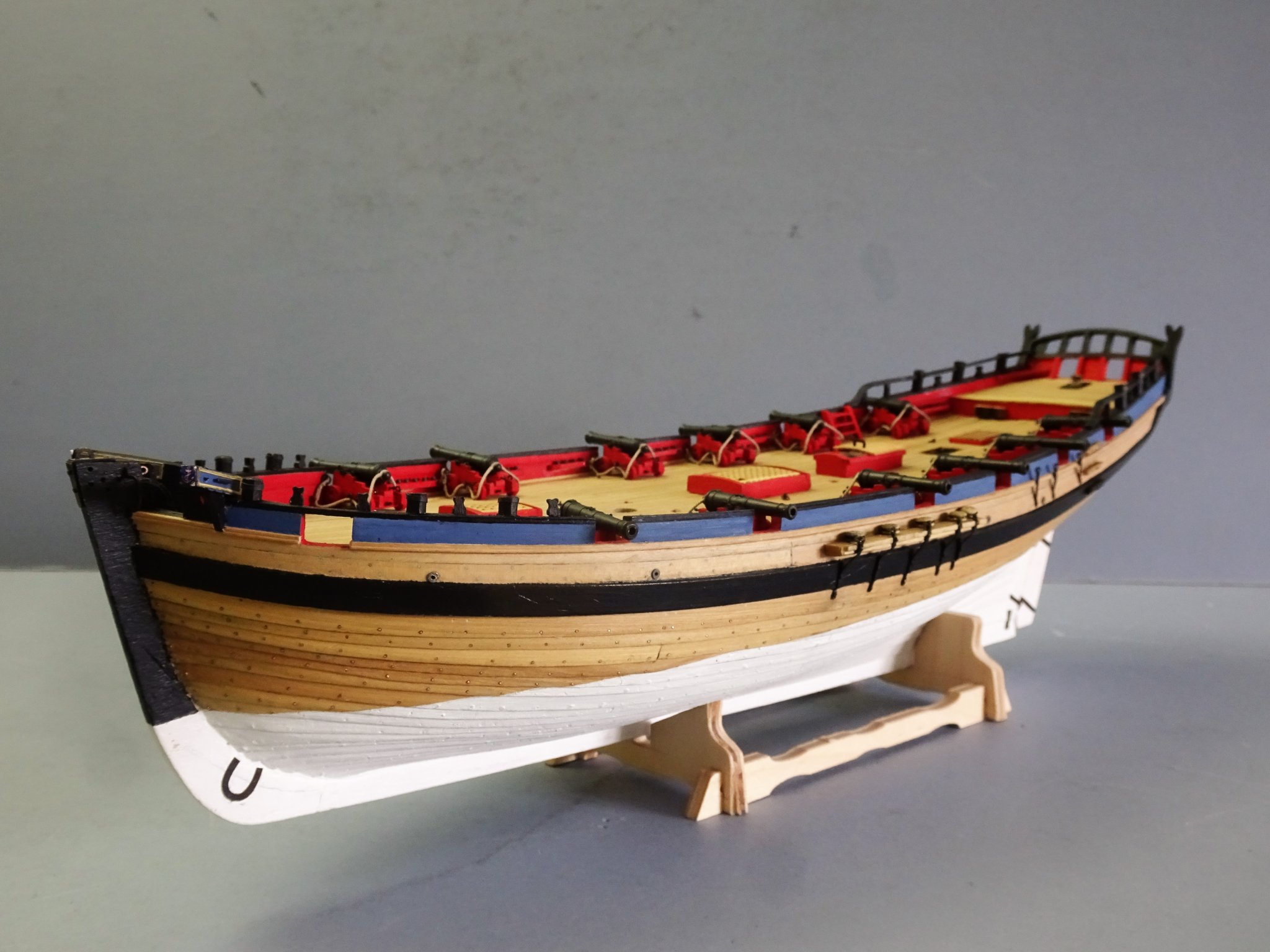
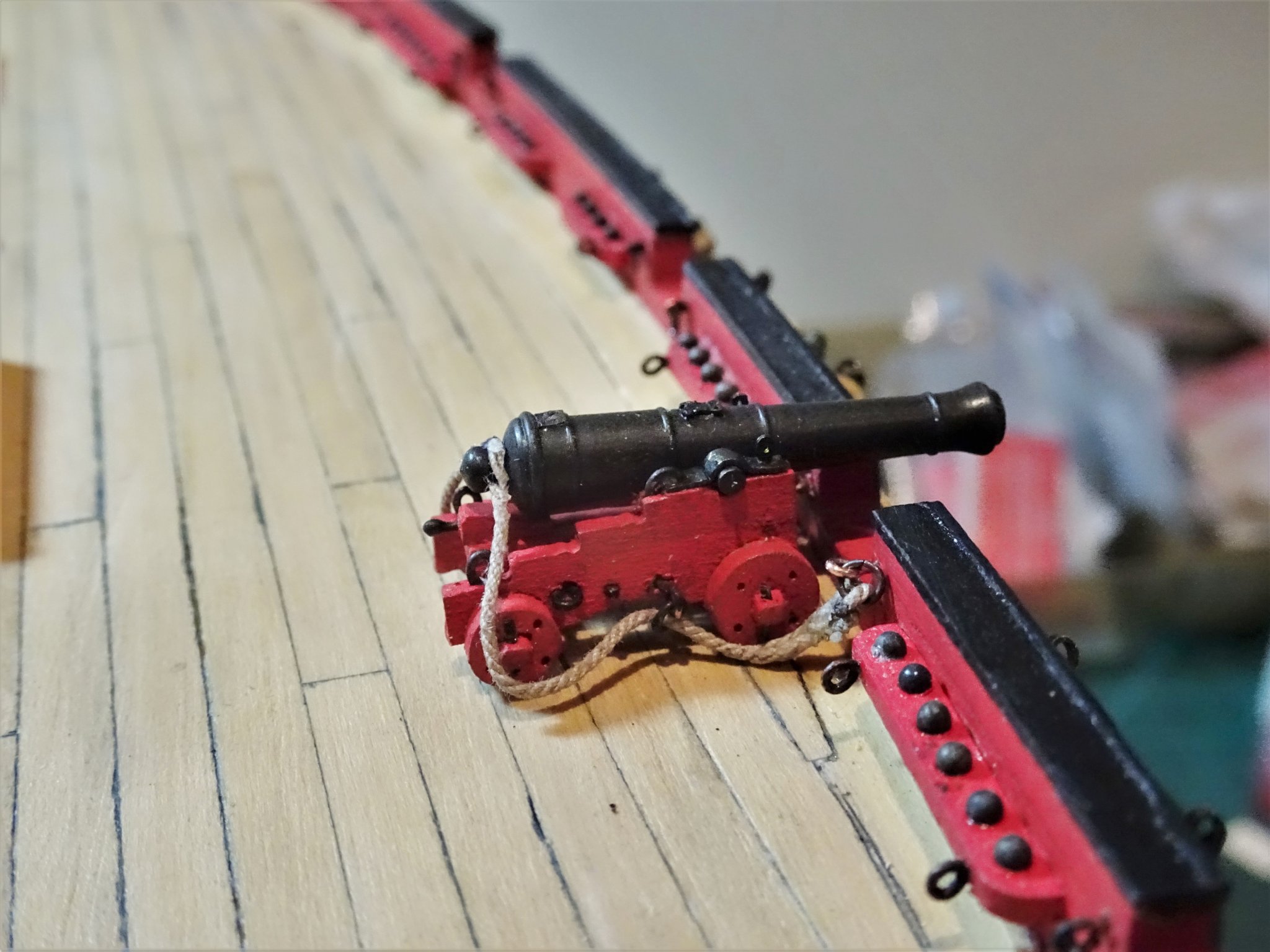
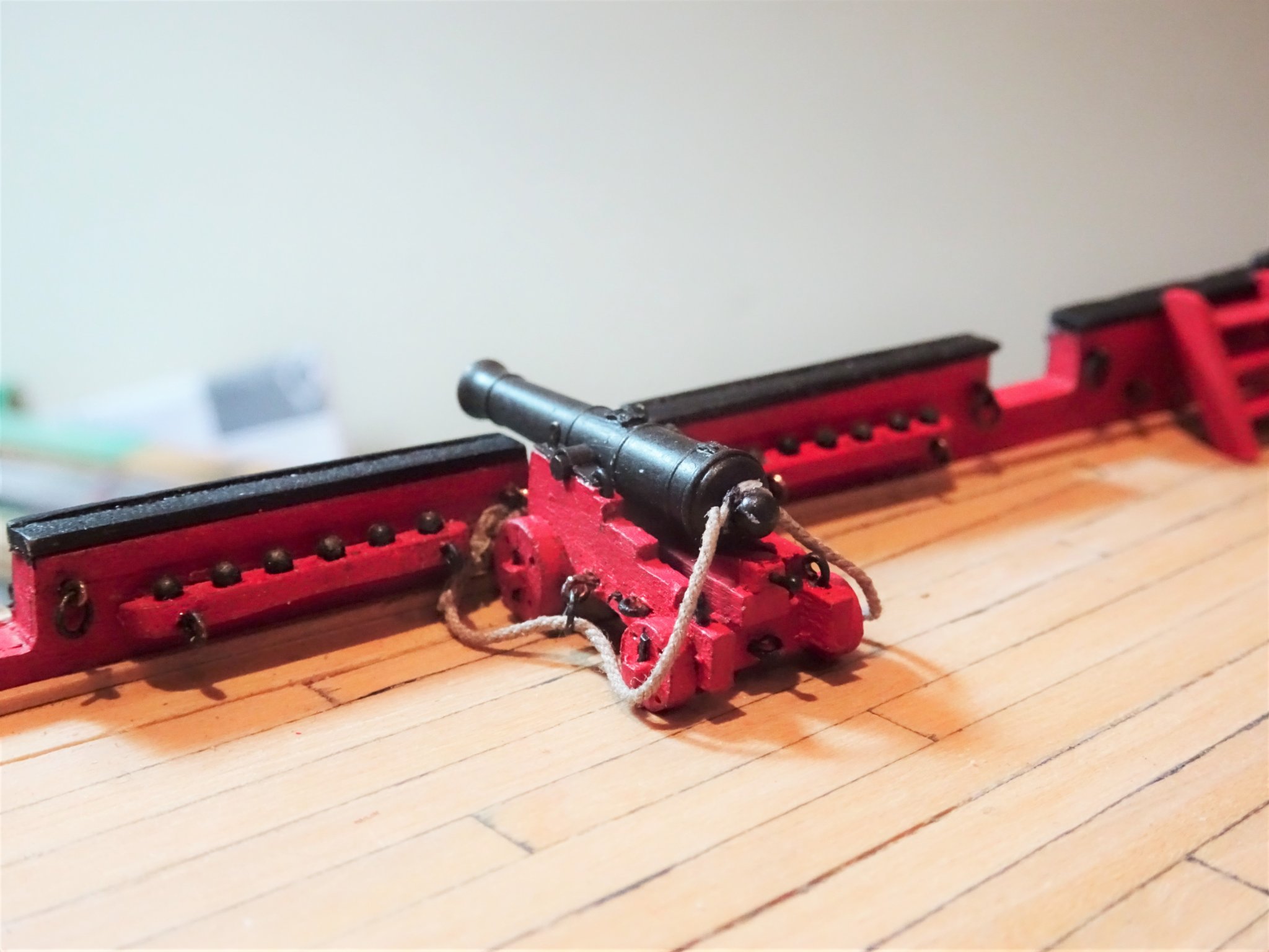
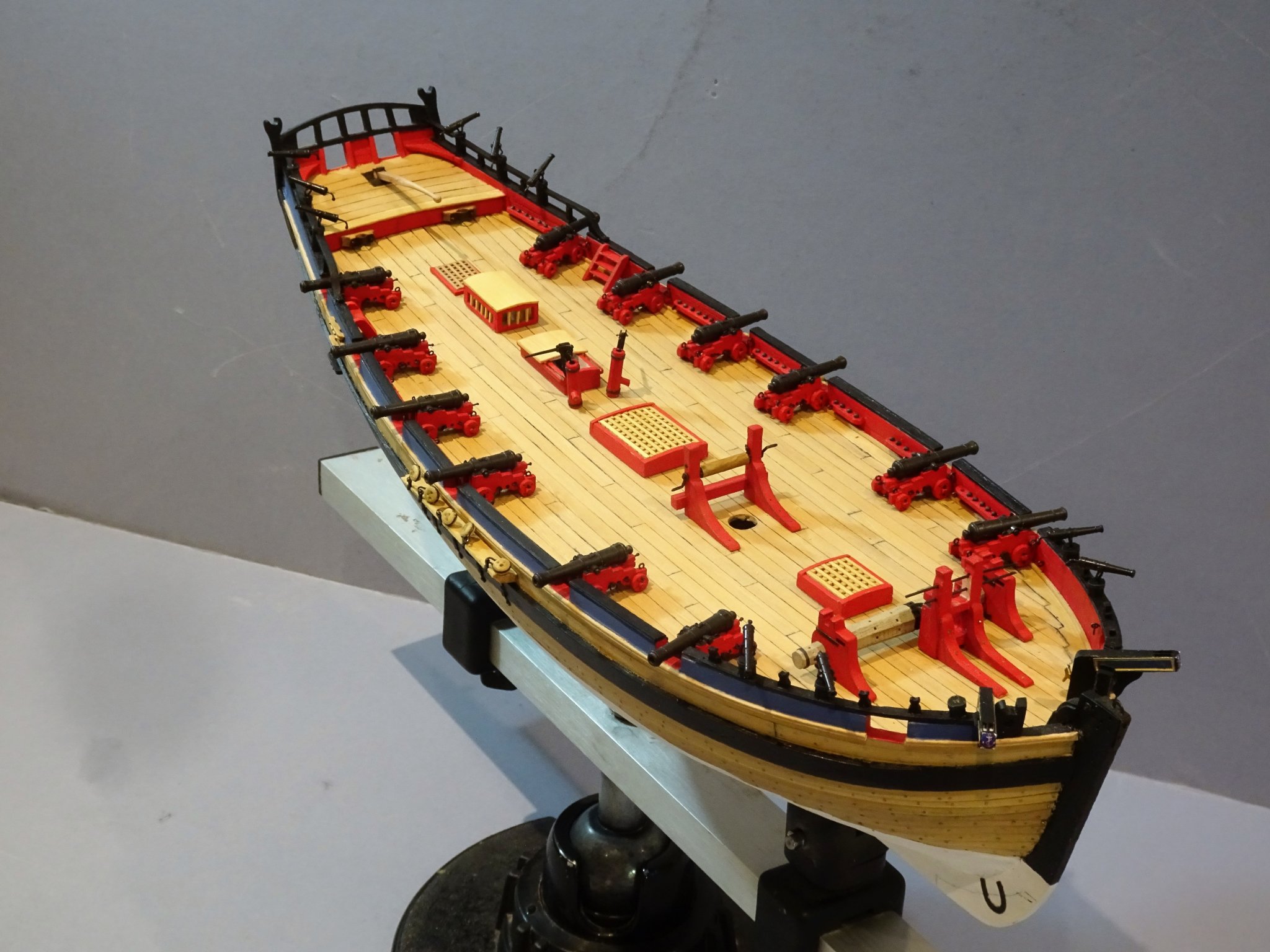
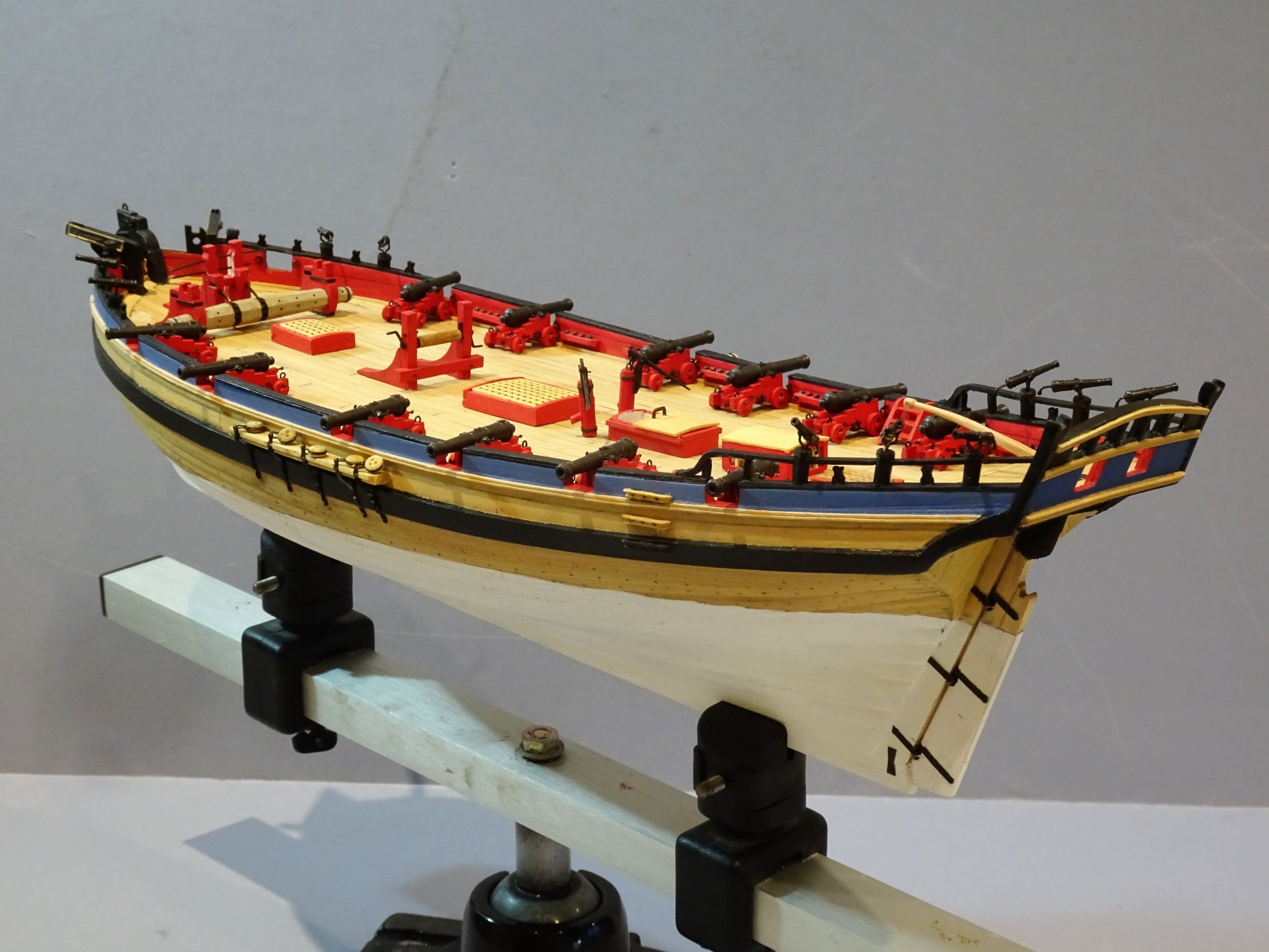
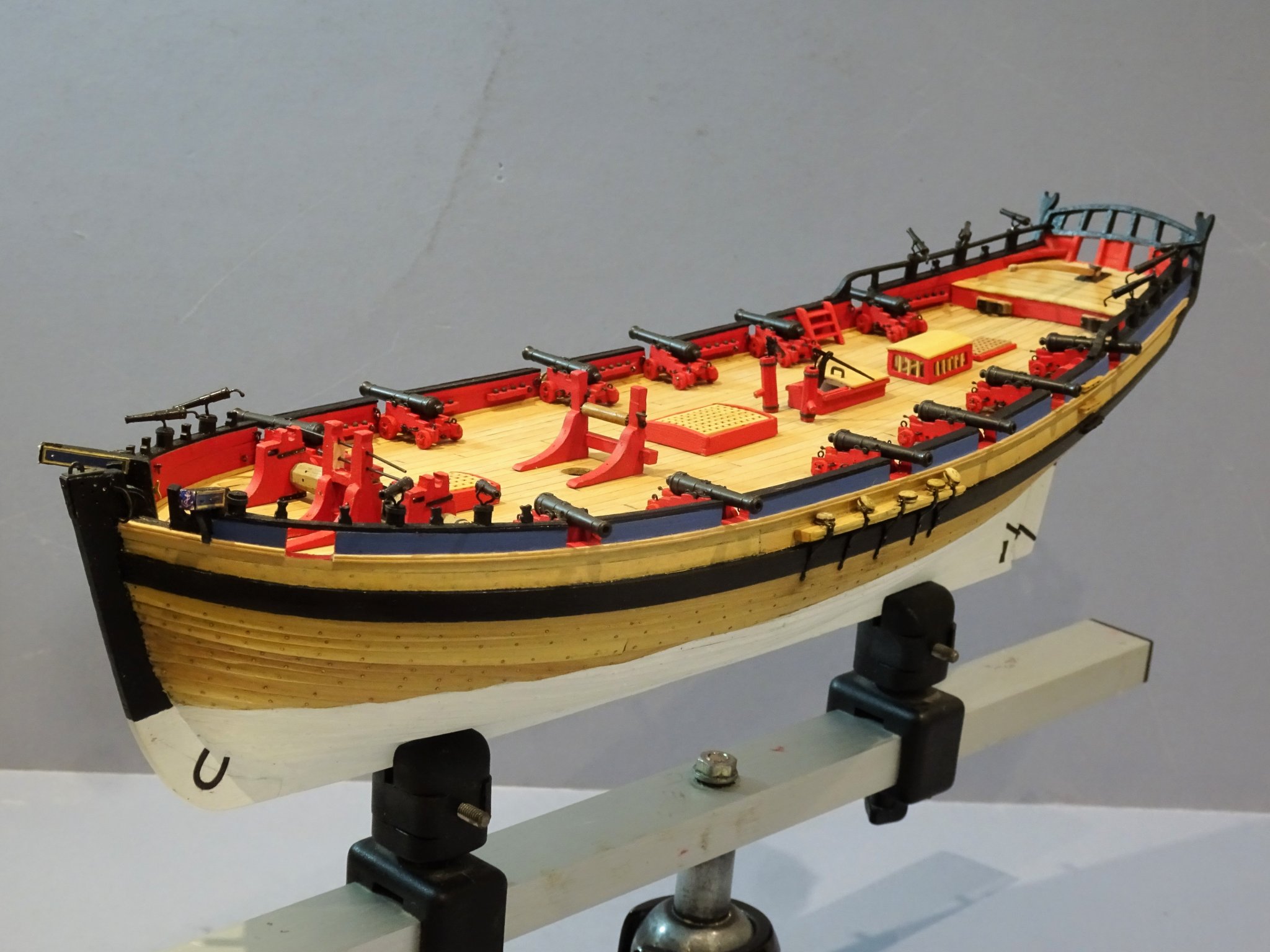
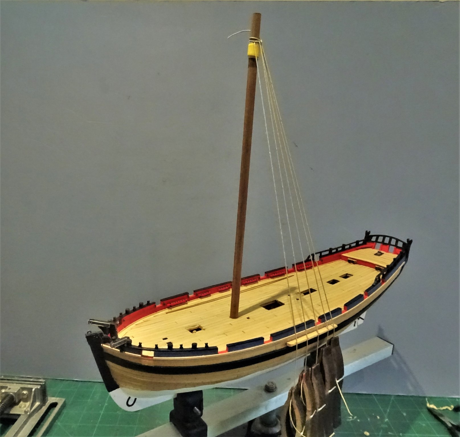
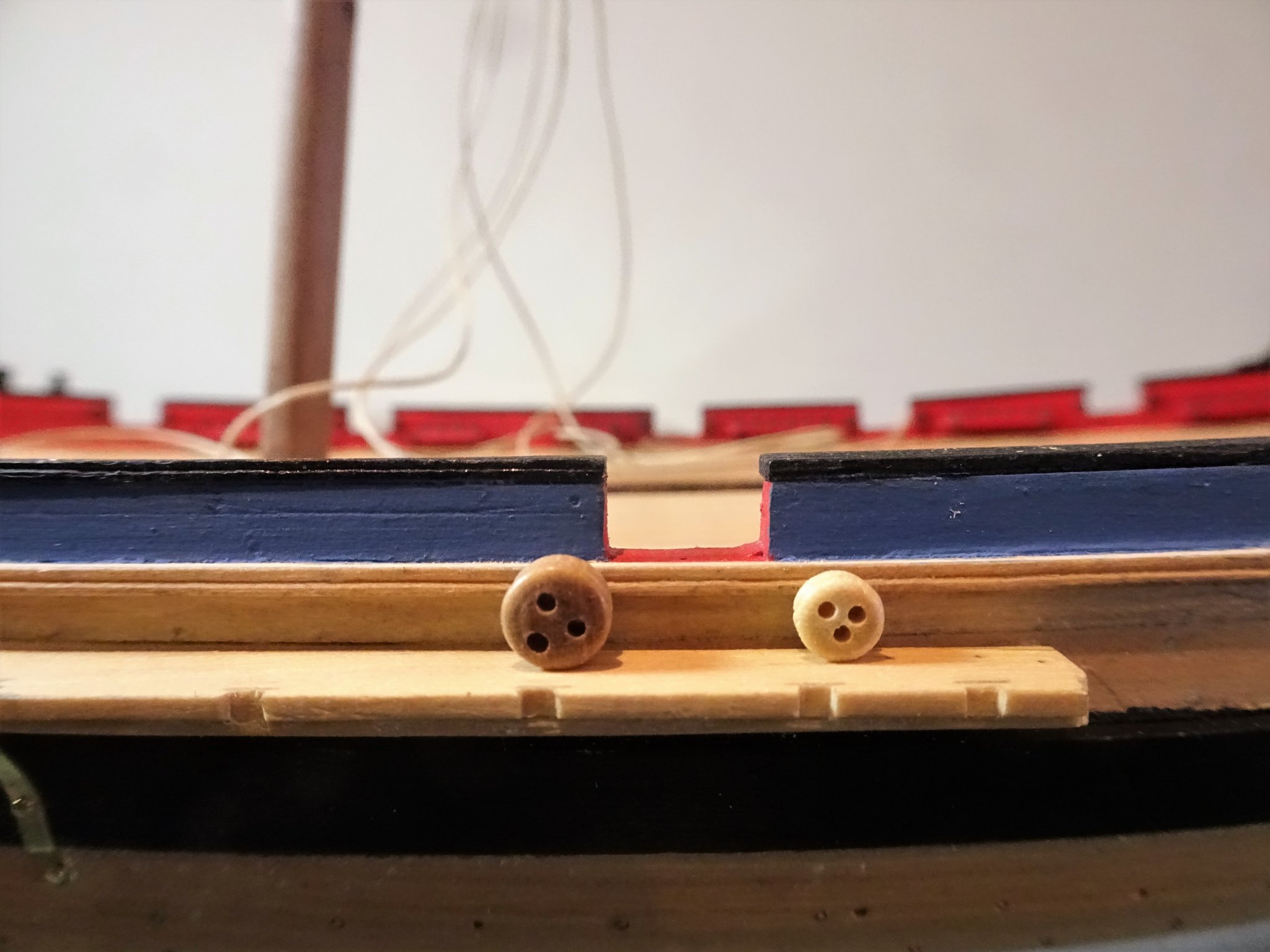
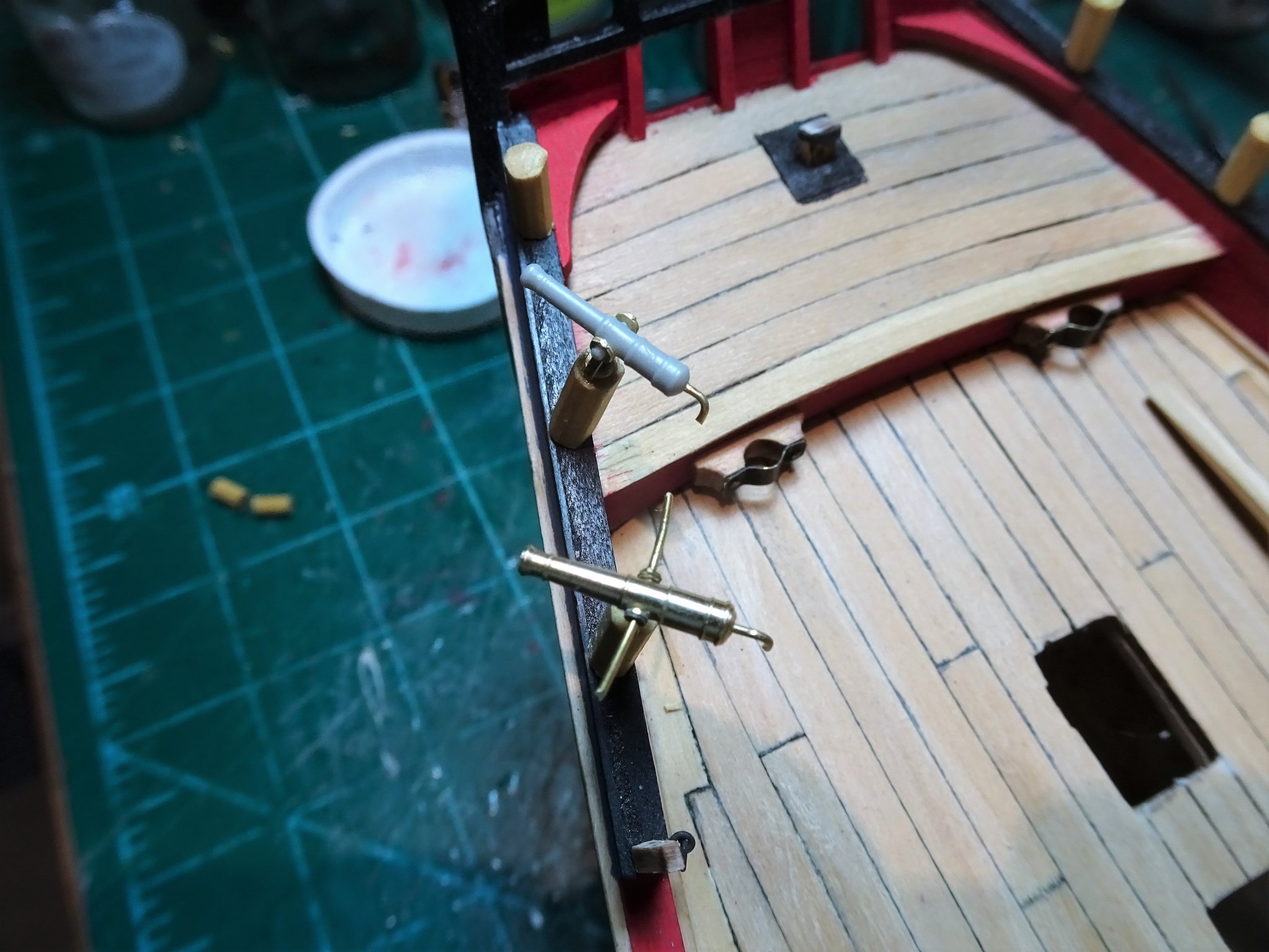
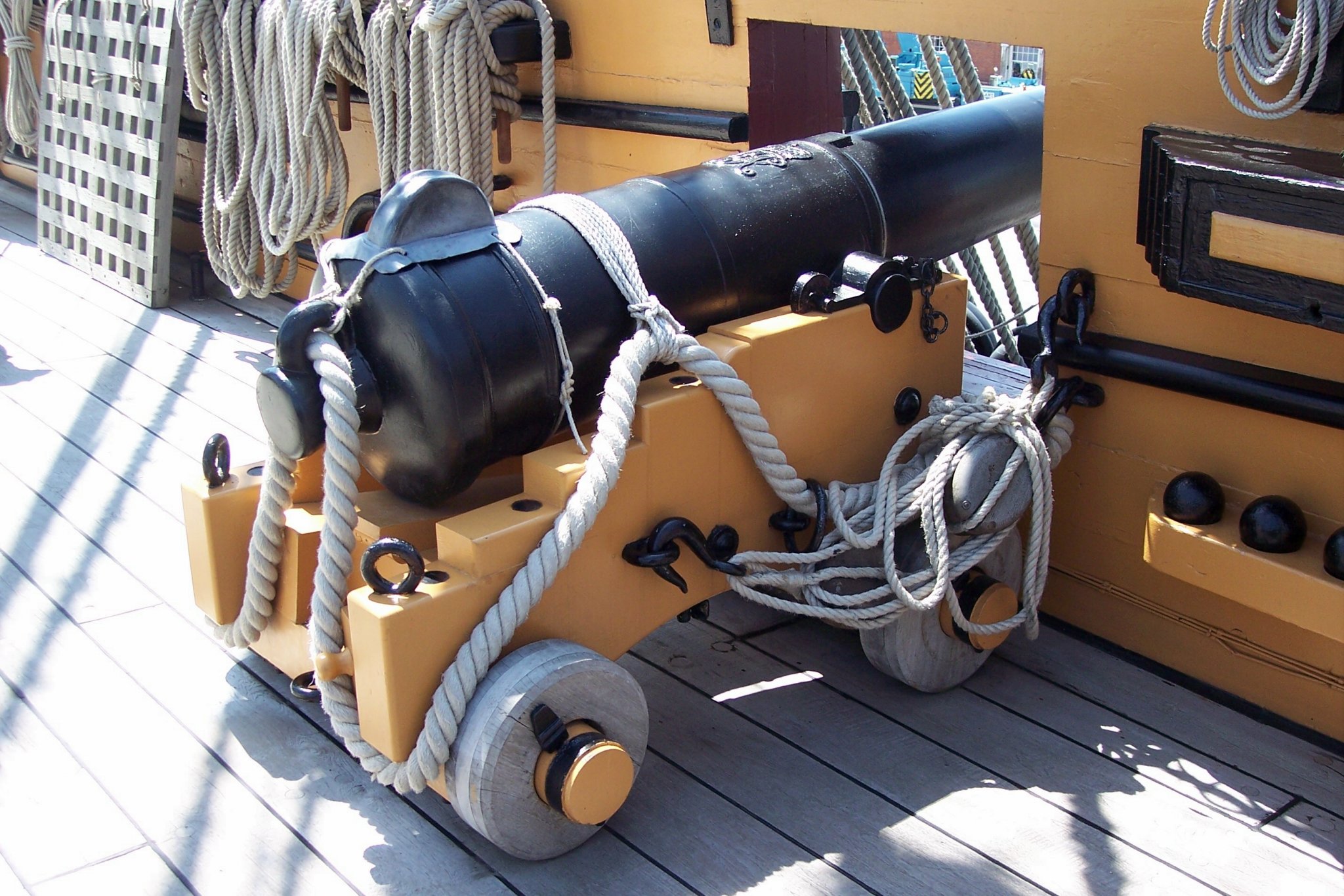
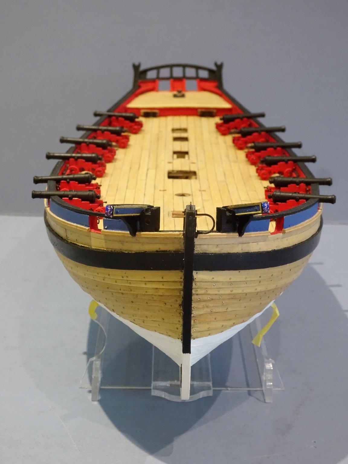
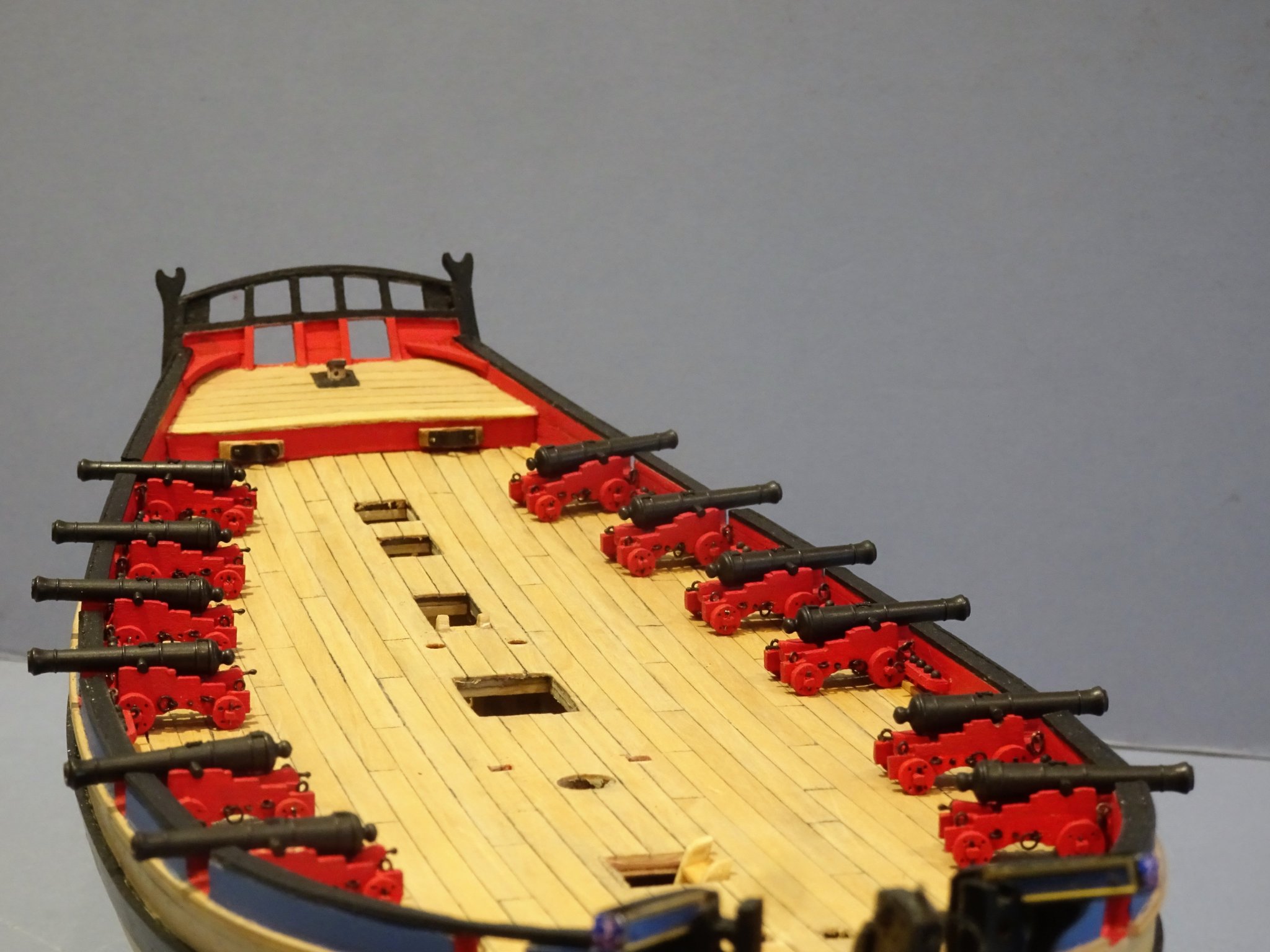
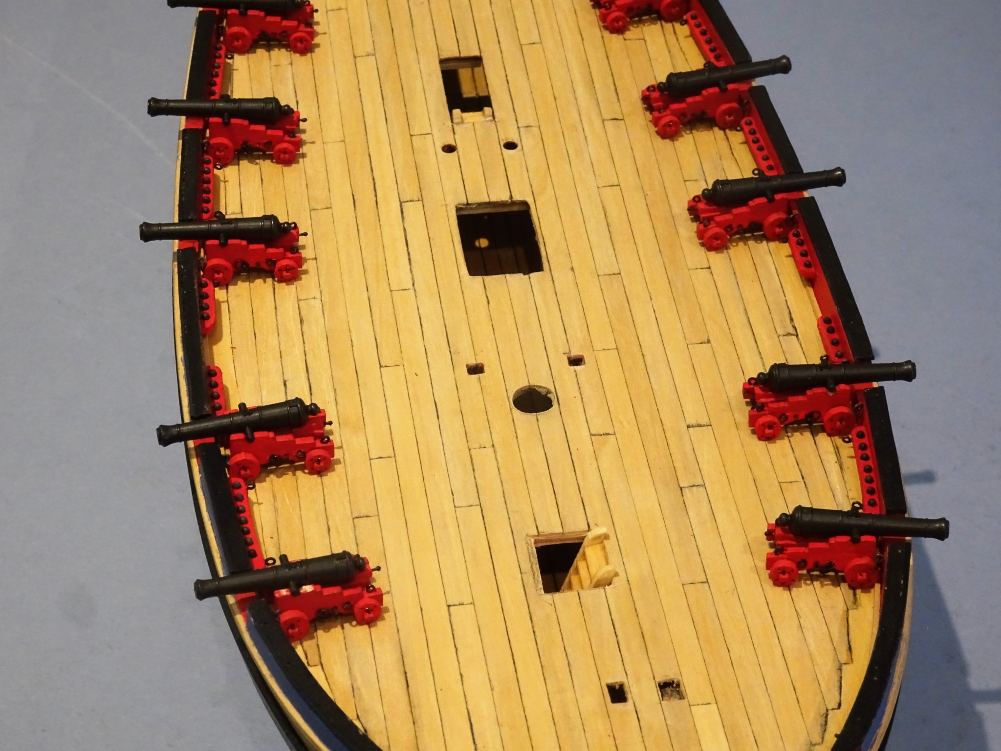
 Post 48 Gun rigging (Part 2) The breeching ropes are at last attached, and scuffs on the iron work touched in. 4005(2) 4001(2) It is time to fix the guns in place along the bulwarks. A small dot of pva is applied to the trucks to fix them to the deck, and the breeching lines can then be attached to the bulwark. 4023 Quite fiddly getting the eyebolts into the bulwark holes without marking the paintwork or even worse the gun blackening. 4024 The eyebolts also have to be orientated to allow the Breeching line to hang properly. 4028 4015 The Breeching lines are not glued down and it’s quite nice not to have to fight them to get them to drape naturally. 4013 4025(2) 4026(2) 4029 I’m quite pleased with the look of her, but now onto those side tackles, 24 tackles to make up, - what joy. 🙄 Happy Christmas to my fellow MSW members, and thank you to those who have shown interest in my build over the past six months. Gun Rigging (Part 3) In this post I am making up the Side tackles, again jigs are required to ease the pain of making up these fiddly little items. 4036(2) The Alert Book indicates 5” double* and single (hooked) block combinations for the side tackles. These equate to 2mm blocks at scale. *I seem to recall that only single blocks were used on small guns such as six pounders, so that is what I will use. The tackle line is given as 2” circumference with 30’ length This scales to 0.25mm ø with a length of 143mm. Making up the tackles I am using Syren Boxwood 3/32” blocks (2.38mm) to give me a little leeway over the tiny 2mm blocks given that hooks must be attached. 4033(2) For the hooks I am using Syren 3mm black plastic hooks, something Chuck no longer supplies, but they are ideal for tackle rigging at small scales, much neater than the equivalent 3mm brass etched versions. For the tackle lines I am using Syren 0.20mm line which will provide a visible contrast to the heavier Breeching lines. The blocks are rigged using a third hand tool, and the tackles are completed on the ‘Gun’ jig. Each tackle assembly takes me around 20 minutes to complete. For the full set around eight hours of work are required, but it feels a lot longer than that. Side tackles are difficult to get looking right; often on models the blocks look over-scale and with the necessary addition of hooks there is only a short space between the two blocks, which makes the tackle arrangement look unconvincing. There is a particular issue with Alert where the securing eyebolts for the tackles are placed in the faces of the shot garlands, reducing the distance between the tackle blocks. In practice with guns run out the tackle blocks are quite close together as apparent on this shot of a twelve pounder on the Quarterdeck of Victory. 12 Pounder gun, Victory Qtr Deck. I much prefer this look of secured tackles rather than stylized cheeses arranged on the deck. The Royal Yacht Squadron it ain’t. Getting a loose frap arrangement at model scale is very tricky, so my approach is to frap the lines and arrange the line ends in a loose coil. This too is somewhat stylized, but it is my option at this scale. Once made it is fairly simple to attach the tackles to the guns. and making up separate coils completes the job. B.E. 24/12/2019
.thumb.JPG.3e5da02c2e093b67ccceaf5a8699874c.JPG)
.thumb.JPG.e4396f4aef4511db88a9cd9b4b8cf711.JPG)
.thumb.JPG.4b77da87b4f00ab0db2aa70d3590c861.JPG)
.thumb.JPG.5c9d15fb9f5d3d58fa03848b7275c1e9.JPG)
.thumb.JPG.171aebfc3b6614405e436d5d36a3a7b2.JPG)

.thumb.JPG.1c09fe8c701f720bfbdc808d375f94f2.JPG)
.thumb.JPG.c06dadd3f1a8014b694b28fbdb19f07c.JPG)
- 335 replies
-
- 26
-

-
- alert
- vanguard models
- (and 1 more)
-
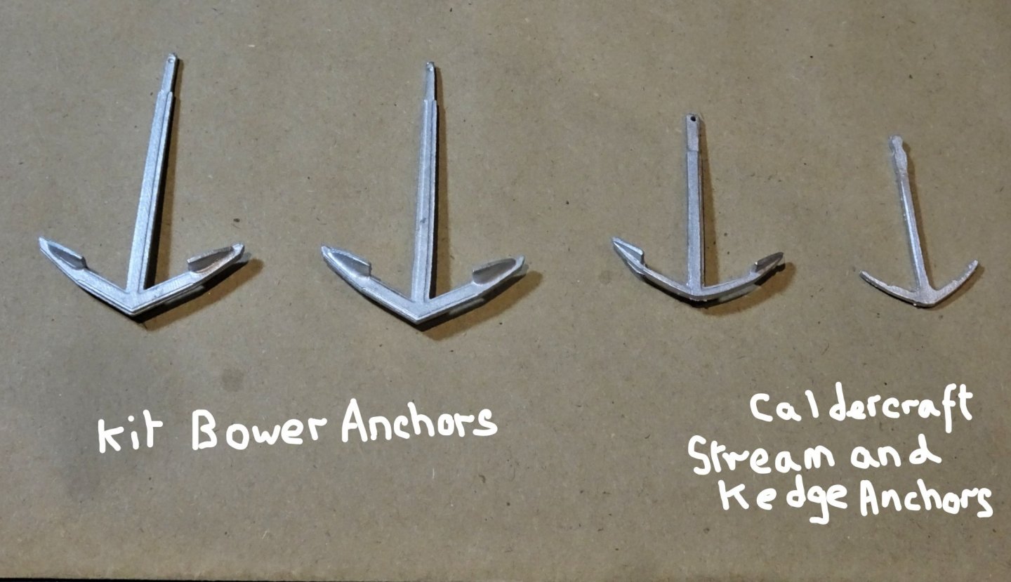
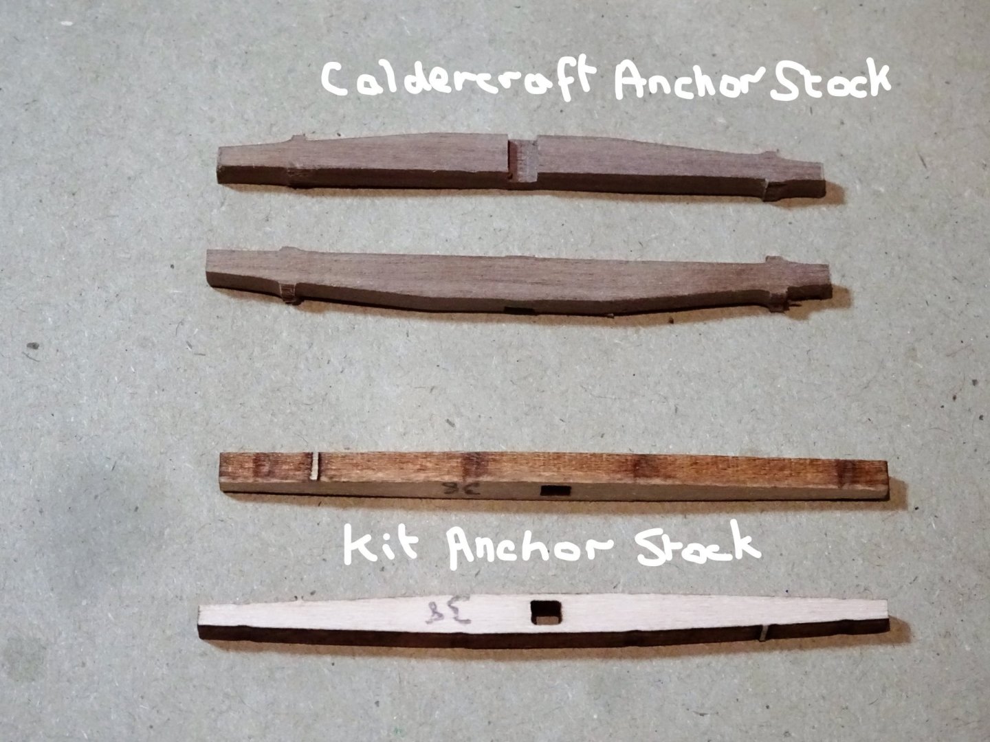
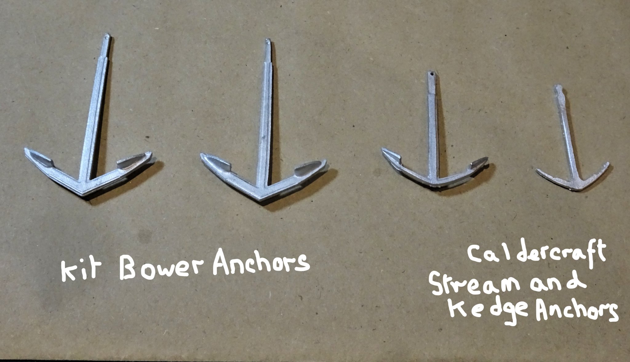
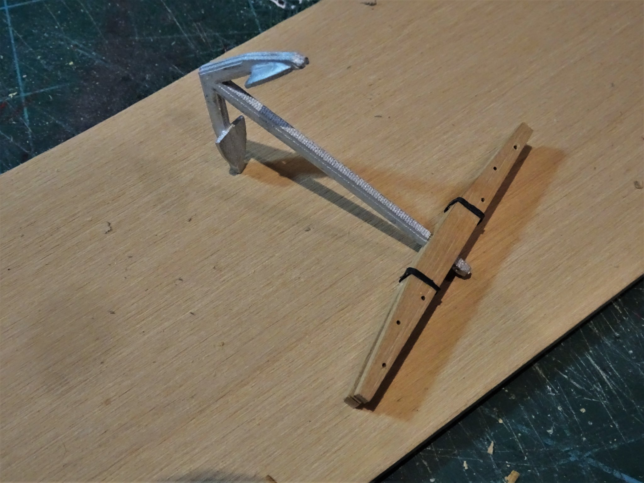
Post 47 Looking at Anchors. Taking a break from the tricky business of gun rigging preparation I’ve had a look at the anchors. According to the Alert Book five anchors were carried: 1 sheet anchor 17/18cwt 2 bower anchor 14/15cwt 1 stream anchor 6cwt 1 kedge anchor 3cwt The kit provides two white metal cast anchors to represent the bowers. They are cleanly made and to an accurate scale for the Sheet anchor (Best Bower), but perhaps a tad large (by 5mm) for the smaller Bower usually stowed on the port bow. 3976lI Alongside are outsourced anchors to represent the smaller Stream and Kedge anchors. I was less impressed by the wooden stocks; they had caught my eye on the photo’s in the kit build manual, looking too thin and without the depth to allow proper shaping. Ideally, they should be deeper in the centre section to allow for a taper upwards towards the arm ends. They did however reflect the taper towards the arm ends when in plan view. 3977lI The issue can be seen here, the upper stocks are from a Caldercraft anchor kit which are properly split down the centre and allow for shaping. The lower stocks are the kit provided items which for me don’t pass muster. Using the Caldercraft stock as a template, replacement Boxwood versions were made cut out of 3mm sheet. 3987 3986 3985 I will leave the finishing off until later and return to a last push to complete the Breeching lines, seven down, five to go. B.E. 20/12/2019

.thumb.JPG.32ffd83b617487802f48f5c832a7c4c2.JPG)
- 335 replies
-
- 18
-
-
- alert
- vanguard models
- (and 1 more)
-
Thank you Gregory, that is just the test version which won't be used on the model, but I think I will have had enough of them by the time I've completed twelve pairs.….. and then there's the side tackles. 🙄 B.E.
-
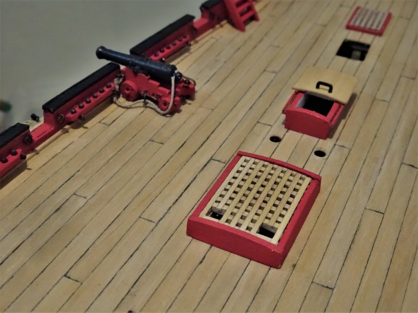
Post 46 Gun rigging (Part 1) For this I will be using Syren rigging line and blocks. The kit provided rectangular single hole blocks belong to a gone-by kit era, and there are many better options now available. Breeching line 4¼” circ; 24’ length. This scales to 0.54mm ø and with a length of 114mm. I am using Syren 0.63mm line. 114mm scale length seems a bit long on the model, the breeching rope needs to have slack to allow for recoil and look realistic, but too much and it simply looks untidy. Conversely one of my pet hates is a breeching line too tight that would allow no recoil at all. I played around with the length and decided on an 80mm line. Attaching the line to the bulwark rings and over the button and thro’ the carriage rings is a fiddly business and connecting the line to the bulwark rings I find almost impossible to do neatly with the gun insitu. One of the objectives is to not have the splice around the bulwark ring too bulky. Modellers cannot do better than follow Chuck’s method as given in his Cheerful build. 3950(2) A simple jig is used to hold the bulwark rings at the correct distance apart. One seizing is made, I use 0.1mm Morope line and a needle, the carriage side rings are slipped over the line and the other seizing made. 3948 The line at the centre is split apart to fit over the gun button, and the job is done. 3957 Trial fit on the deck. 3958 Difficult to properly arrange the breeching rope at this stage as neither gun nor rings are yet fixed, but the prime objective of confirming the line length is achieved. I can now at last fix some of the hatches in place. 3959(2) 3963 The Main hatch grating has been modified to allow passage of the anchor cables. Twelve sets of Breeching lines have now to be made up. Not one of my favourite jobs, a rather tiresome exercise. B.E. 18/12/2019
.thumb.JPG.2a51db4cf012a48a5e91e3e6830956e8.JPG)
.thumb.JPG.a964bf2afb26bbebfa25bdab1fba4942.JPG)
- 335 replies
-
- 17
-
-
- alert
- vanguard models
- (and 1 more)
-
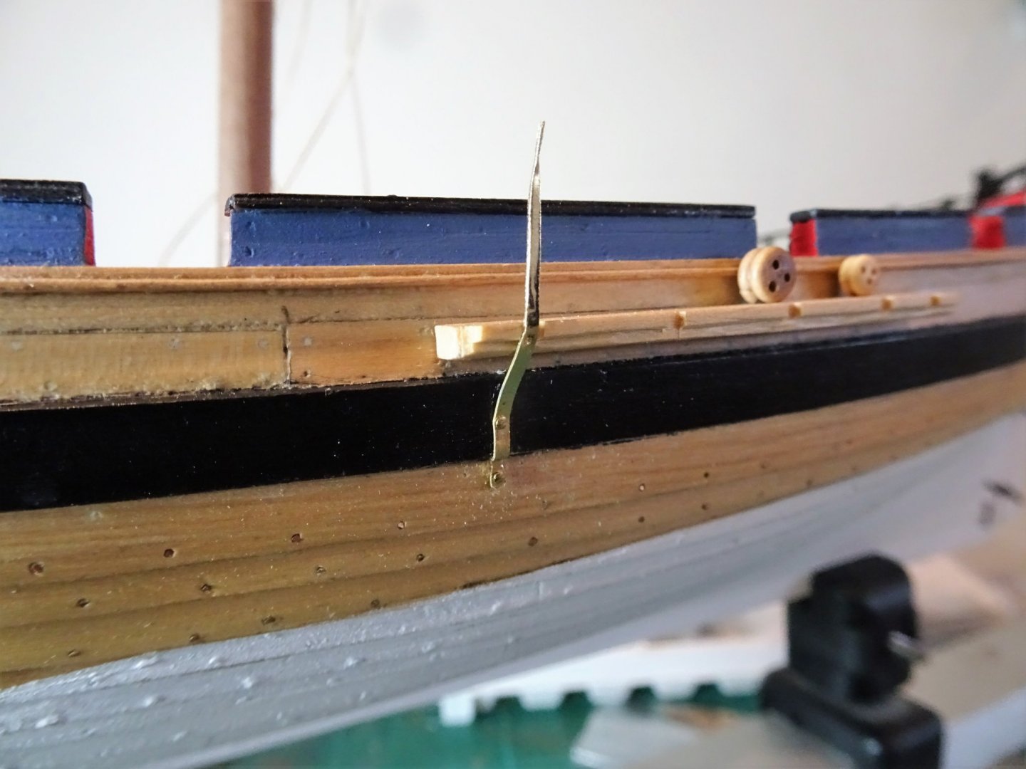
Post 45 A few more bits and pieces. Scuppers These are given as four in number each side with a diameter of 2½” (0.99mm at scale) 3881(2) They are made from thin slices of aluminium tubing flattened on the anvil. Iron plates for Backstays As with the Chainplates I fashioned these from some brass strip. 3904(2) According to the Alert Book drawings these are for (from aft) the Running Backstay, Running Backstay Tackle, and Standing Backstay. (set up with deadeyes.) The kit rigging follows the Alert book. The subject of Backstays. There is a confusion in my mind about the notation used in relation to the rigging in the Alert Book. There are several instances where the description for the same line varies across the different drawings. For instance, drawing H22/2 shows ratlines across all five connections along the channel whereas on H4/1 they terminate at shroud four. The book narrative notes that:- a fifth pair of deadeyes were added for the Standing Backstay, - on the channel and shown in drawing H4/1 However, drawing D1/1 annotates this as being a shroud deadeye, with the first of the iron plates aft of the channels as relating to the standing backstay. The aft two plates being for the standing end and tackle of the running backstay. So how many standing backstays are there? Strangely, the rigging table in the Alert Book (taken from Steel) does not list backstays for the lower masts, only the T’gallant standing Backstay is mentioned. 3906(3) Backstay rigging as I recognise it. The use of deadeyes on the iron plate, ostensibly the same size as for the shrouds along the channel doesn’t sit easy with my eye. Tackles are usually seen hooked into iron plates on Cutters. The question remains, if the first iron plate is indeed for a standing backstay, what size line is it, and is the use of deadeyes a drawing error. The kit indicates use of 0.75mm ø line which scales up to a 6” circumference line, as with the shrouds. Steel gives the circumference of the shroud lines as 8” scaling to a 1mm ø line. None of the cutter models I have seen have a deadeye arrangement for this standing backstay, except those based on Goodwin’s Alert book, which the kit follows. 3301 The Hawke model with the usual tackle secured Backstays. I note that Lennarth Petersson in his book Rigging Period Fore-and-Aft Craft shows yet another variation on backstay tackles, but tackles they are, not deadeyes. Having looked extensively thro’ all my rigging books and at many cutter models, I have decided not to use deadeyes for the backstays and I have formed all the plates to take hooks. How I will rig the tackles I can now safely leave until later. B.E. 16/12/2019
.thumb.JPG.9fa38bd78fb2099832e66db616561efe.JPG)
.thumb.JPG.b76f856612729cf2d04f3c6d9e1ebd32.JPG)
.thumb.JPG.8f2c2227347db6aee172b72e8ac61751.JPG)

- 335 replies
-
- 16
-
-
- alert
- vanguard models
- (and 1 more)
-
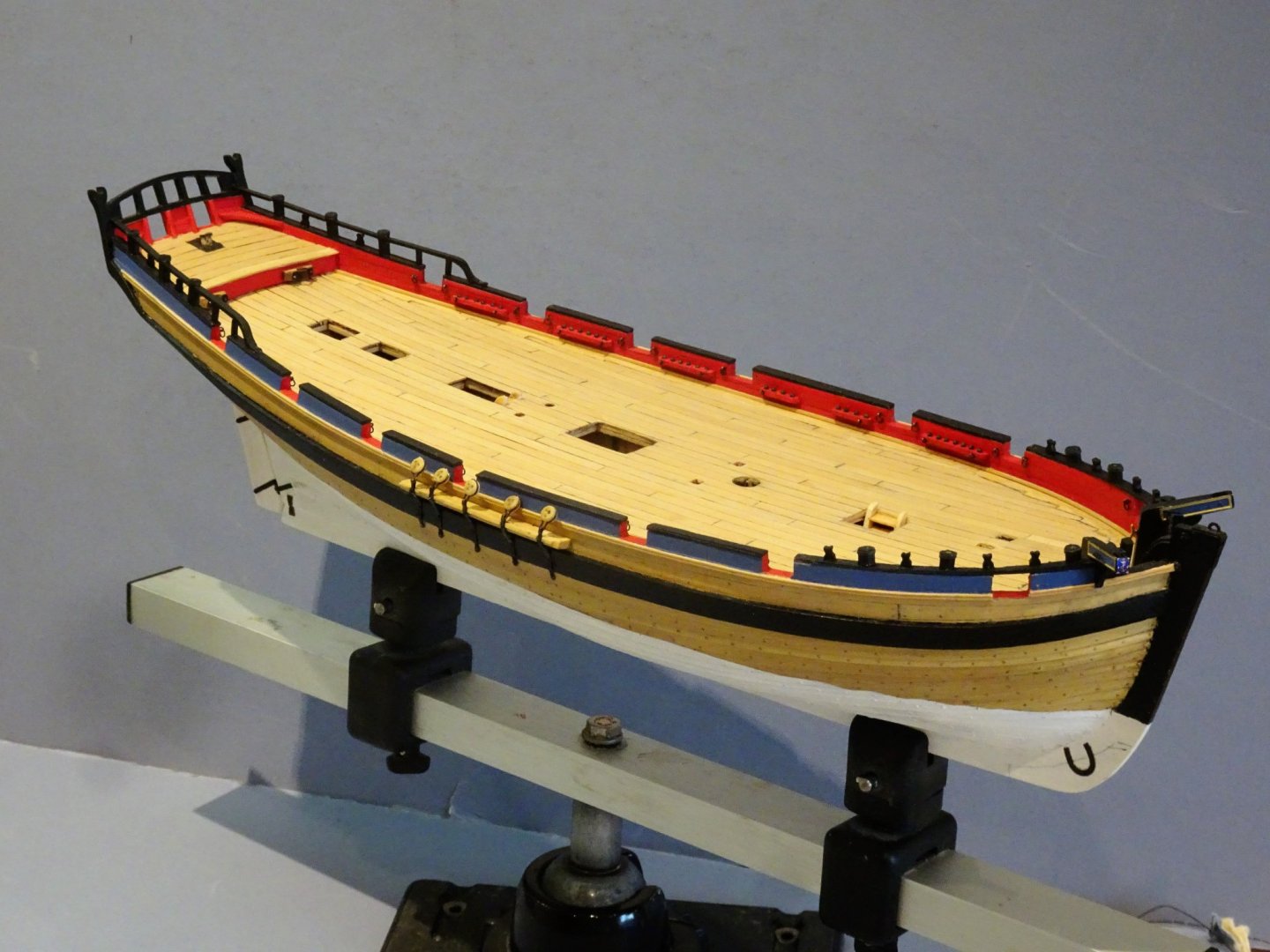
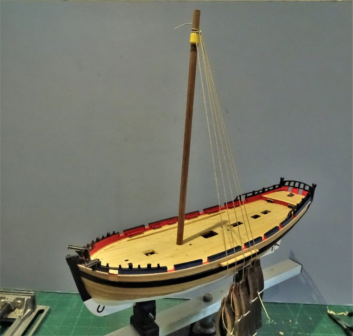
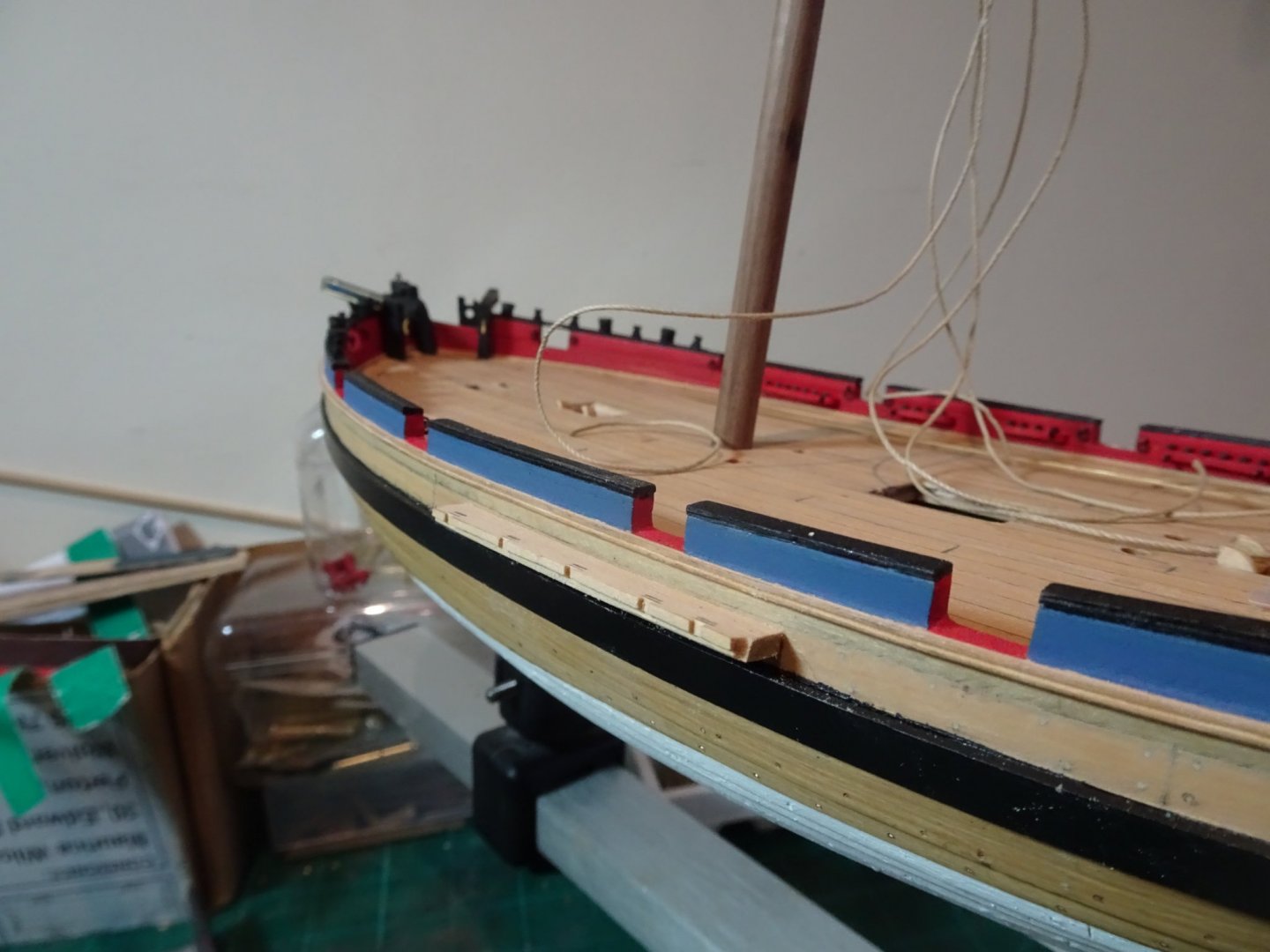
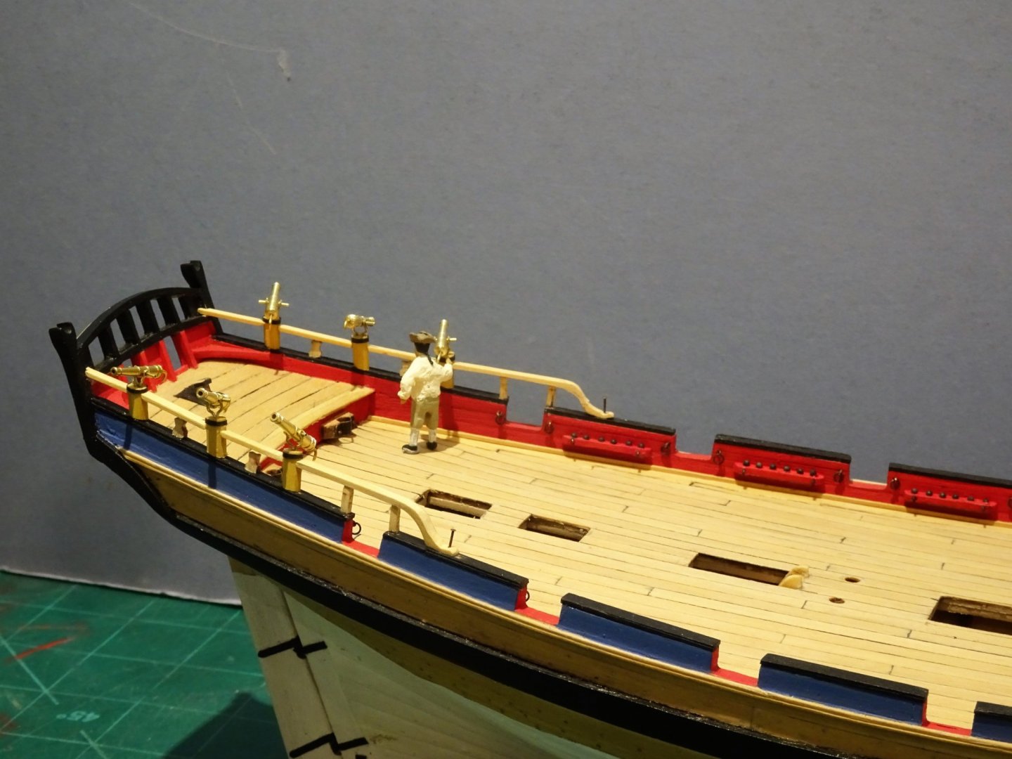
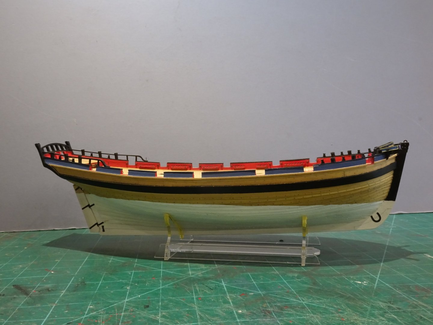
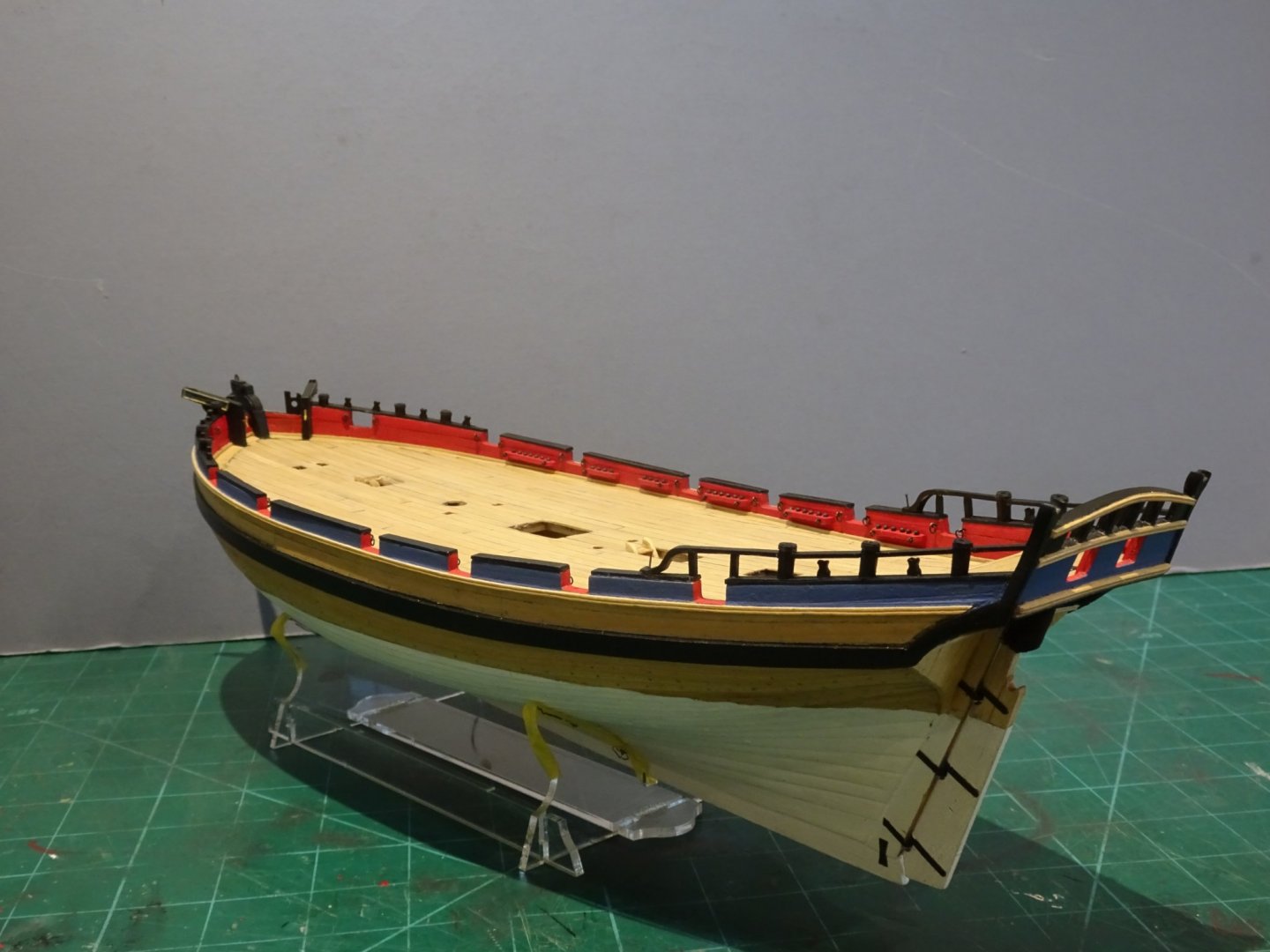
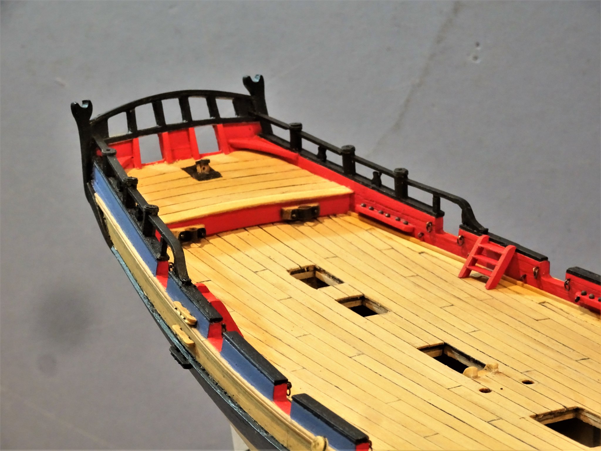
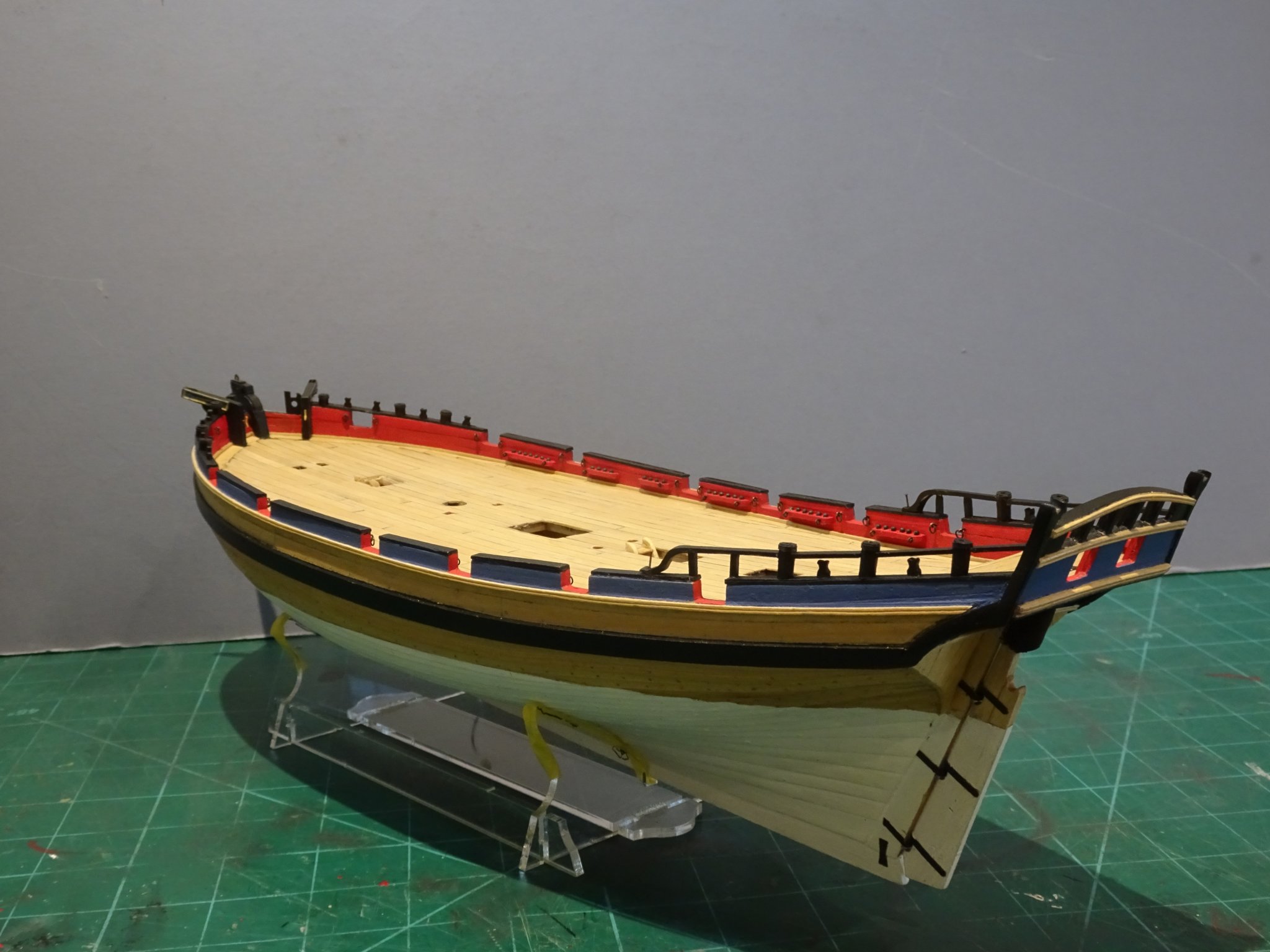
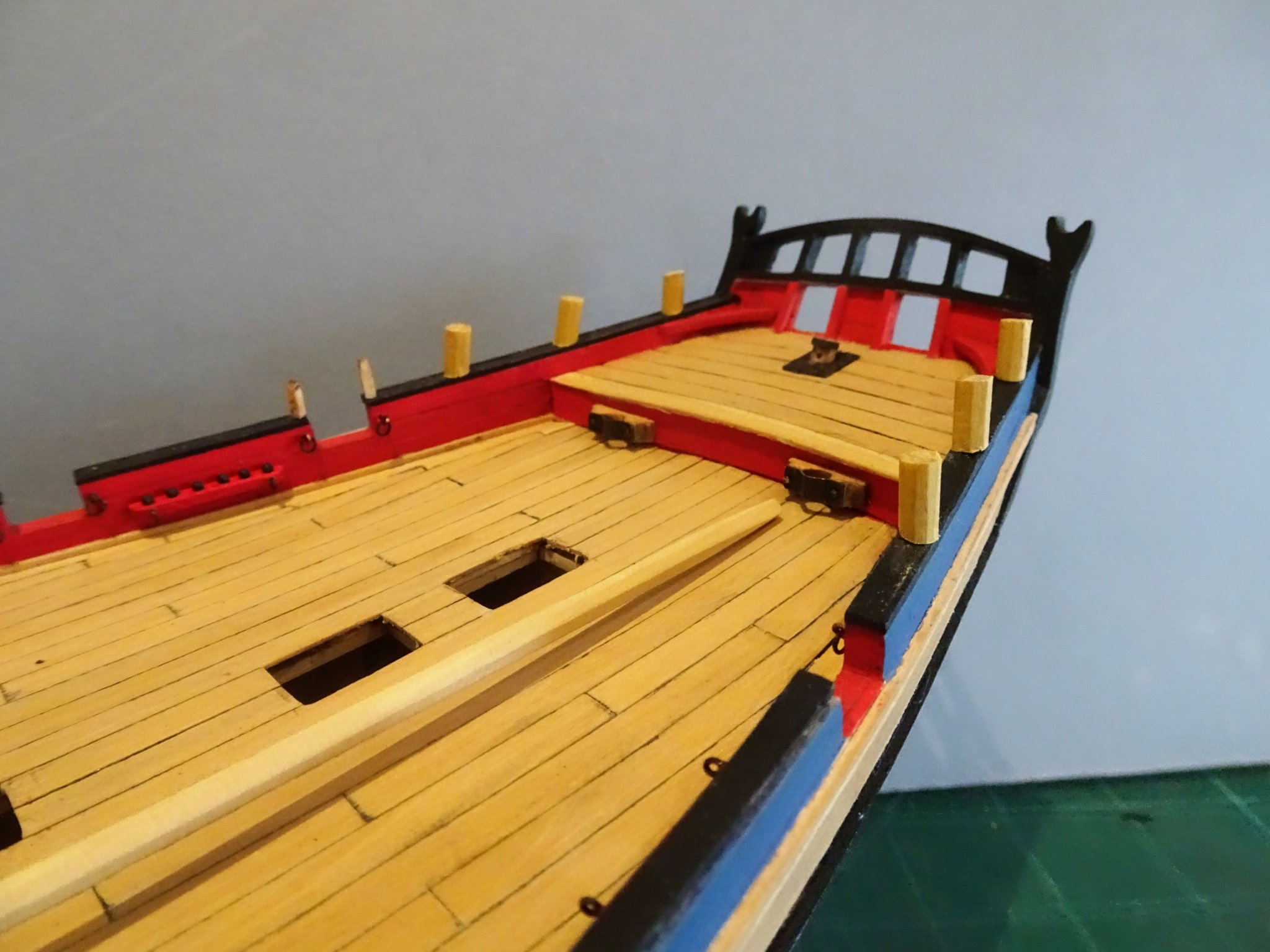
Post 44 Bits and pieces Side steps These are plain affairs that will stand a little enhancing with extra profiling. The kit items do however include the hand holds. Two outboard steps are indicated although I note that four are shown on the Marshall painting. Same problem here as with Cheerful; it looks like there ought to be additional steps. Two steps may just pass muster with the open drift arrangement, effectively an extra step, but the distance between the upper of two steps and the closed in Drift rail is the same as the distance taken up by both two lower steps. 3862(2) For this reason, I have decided to fit three outboard steps, the added third step being fixed just above the sheer rail. Inboard steps: the kit doesn’t provide these, whereas the Alert book shows a three-step inboard entry ladder between deck and Drift rail. With my current set up a ladder would cover the shot rack and interfere with gun side tackles for the second from aft gun. Still, I think there should be steps, so it looks like re-visiting the Rough-tree rail and shot rack. 3630 I identified the problem as the hance coming too far forward on the Drift-rail, preventing the ladders clearing the side tackles. Worth mentioning that use of pva allows for painless removal of the rail, quite a delicate fitting, which would not have been the case had I used ca. I keep use of ca to the absolute minimum on my builds, there is often a need to do modifications and ca tends to make the wood brittle and using acetone to loosen ca can be a messy business. 3852 The hance has been modified, the shot rack moved aft, and the inboard ladders installed. 3864(2) 3860(2) Layout looks more logical to my eye now. Not yet ready to fix the deck fittings but it’s been a while since I reviewed the layout. 3839(2) 3840(2) 3845(2) 3843 3842 3838 Time to move on. B.E. 12/12/2019

.thumb.JPG.e3dcbadea8f25a58282d78114c807764.JPG)
.thumb.JPG.20050d7e67cb133f037ad906515a5ac0.JPG)


.thumb.JPG.7bbcde39eba1518fa26612191a507512.JPG)

.thumb.JPG.09bcae2123f4df7057d9230fa2a660e6.JPG)
.thumb.JPG.d175077047e1c978056b78ae015cdee1.JPG)
.thumb.JPG.872f9b0cb16108ad8884efb130d1a5cd.JPG)
- 335 replies
-
- 27
-
-
- alert
- vanguard models
- (and 1 more)
-
Nice result Skip, your hard work has paid off. if you're going for authenticity, remember that the rudder straps over the copper plating were made of a cuprous alloy, and would be of a bronze colour. B.E.
-
I did a test and found that the deadeye wasn't affected by the diluted blackening fluid so I just dunk the whole lot in, and then quick dry with a hairdryer. Cheers, B.E.
- 335 replies
-
- 1
-
-
- alert
- vanguard models
- (and 1 more)
-
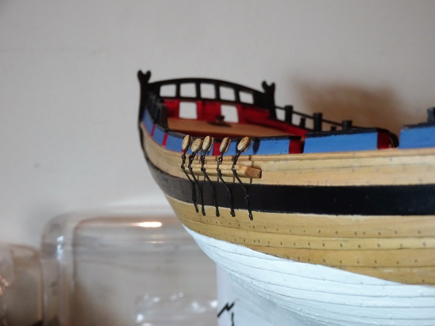
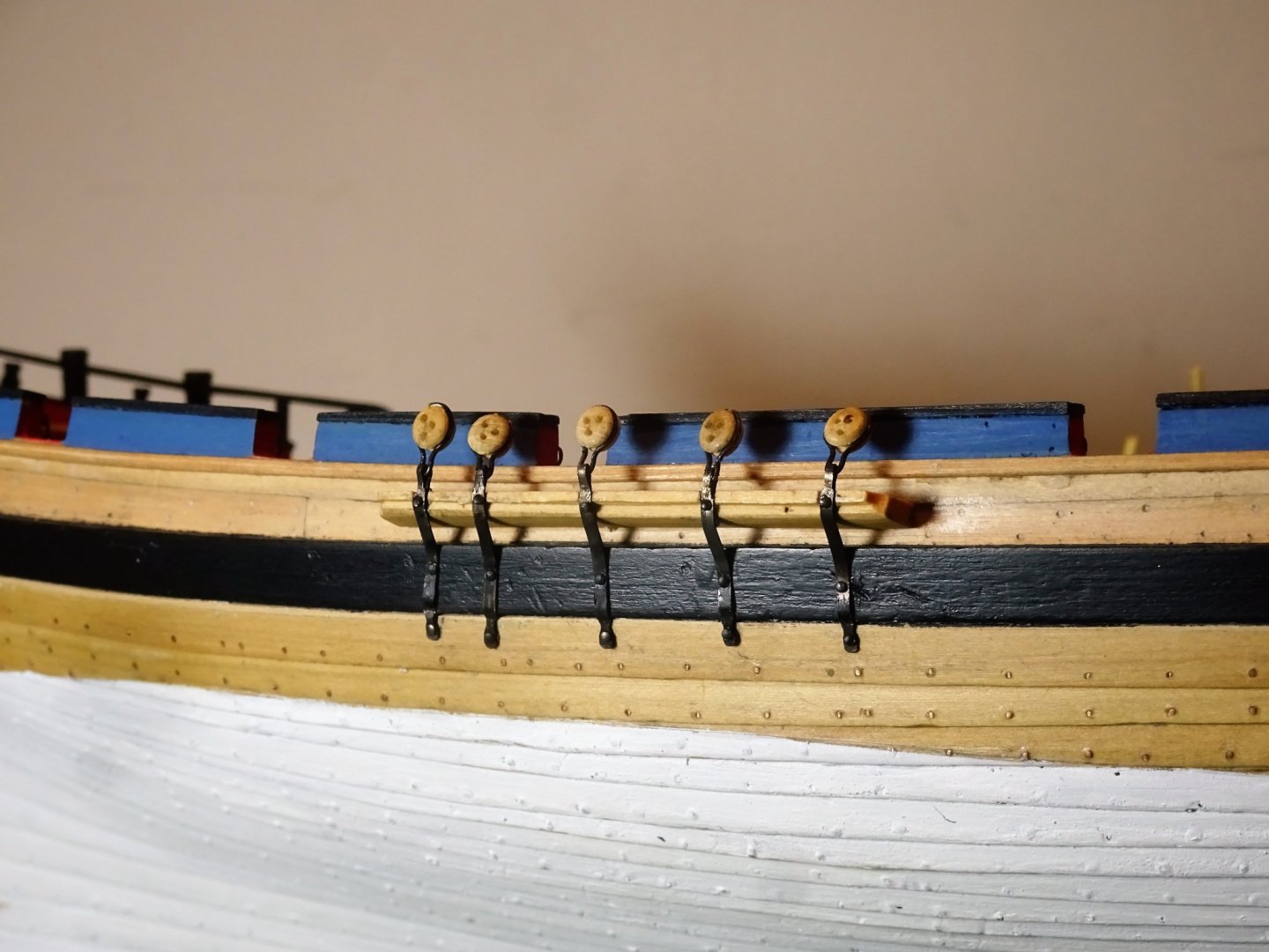
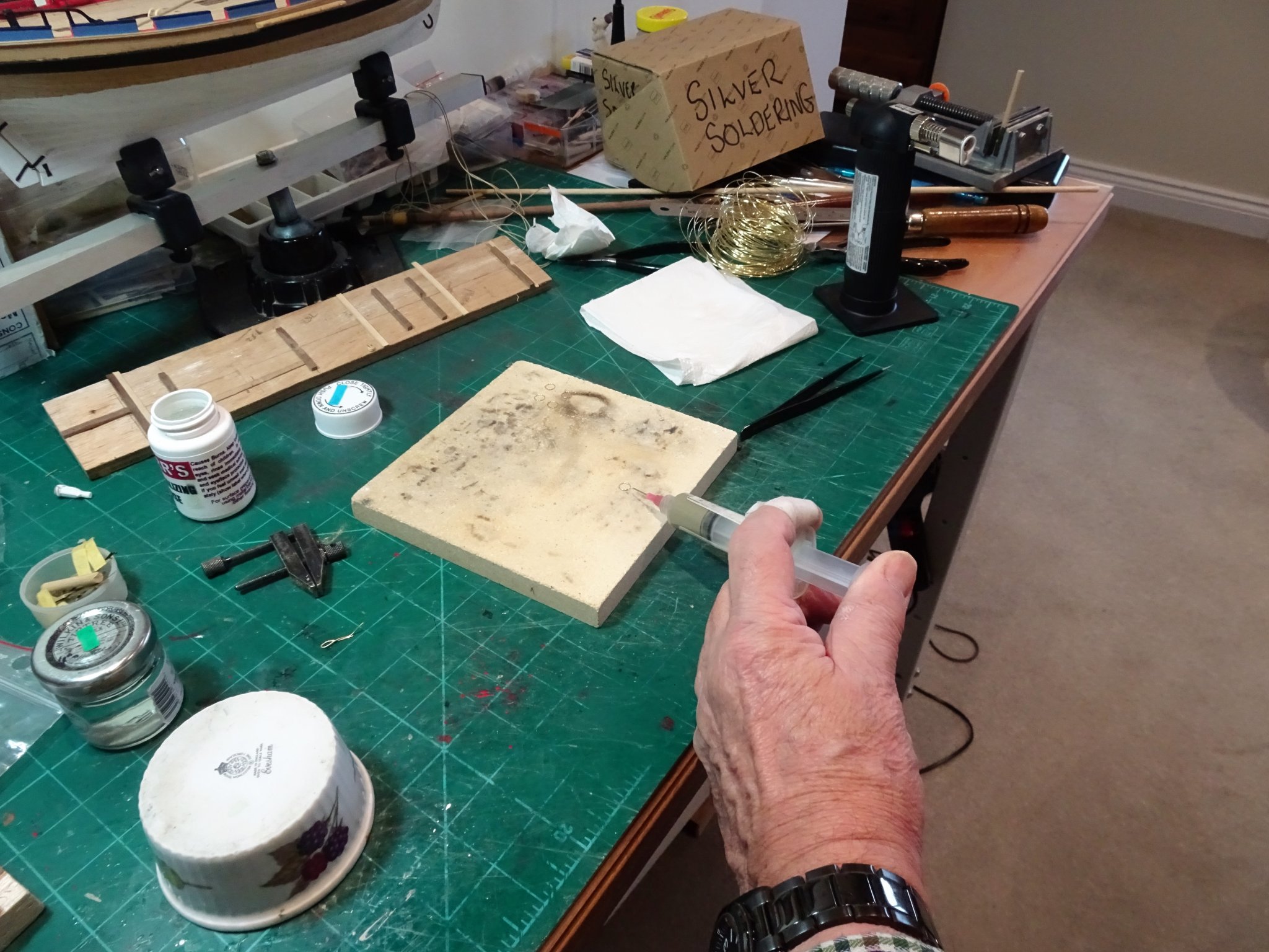
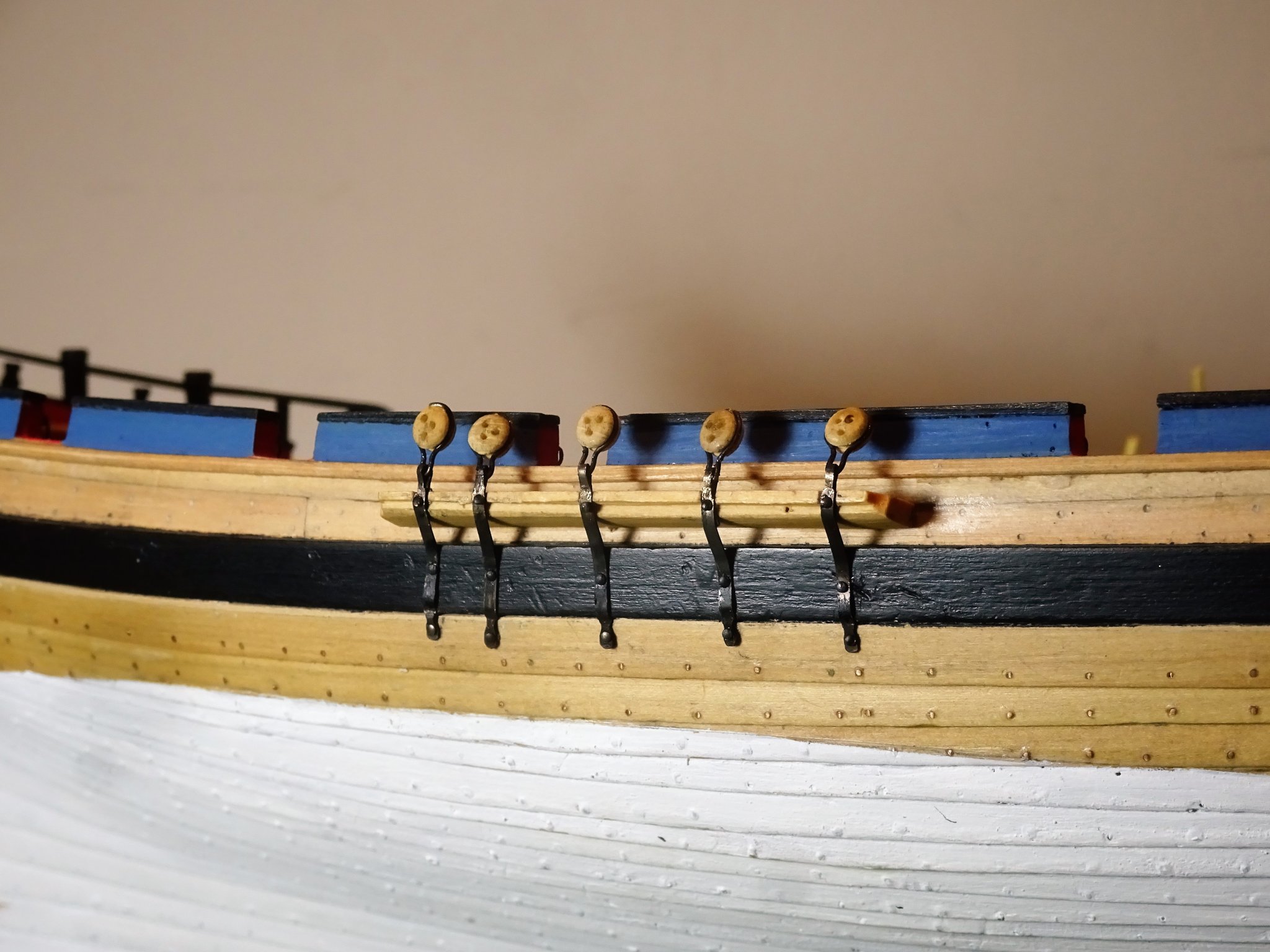
Post 43 Iron work along the Channels. I prefer the look of a finer Chainplate and smaller deadeye so some extra work is involved in shaping the plates, drilling the three bolt holes, attaching to the strops, and blackening the metal. 3731 Having formed the basic plate, the first action is to test fit along the hull, mark the bolt holes, remove and drill, and generally clean up and file in the taper and shoulder where the plate fits around the Deadeye strop. The second part of the exercise is making Deadeye Strops. This is a fairly simple exercise if you invest in a silver soldering kit. A ring is made using 0.5mm ø Brass wire wound tightly around a nominal 5mm dowel rod and snipped. 3735 Applying the silver solder paste to the joint which should be very close. 3734(2) Heat is applied until the silver flashes, and the jobs done. The success or otherwise of the joint will soon be apparent when the ring is squeezed around the deadeye to form the strop. 3738(2) Sufficient excess of wire is necessary over the actual deadeye size to form the strop and a little trial and error may be required to gauge this. 3745(2) The two elements can then be brought together for blackening and fitting. Fitting is probably the trickiest part of the exercise, ensuring the deadeye tops look level along the Channel. 3748 The Starboard set completed. 3749(2) The copper bolts securing the clinker planking are evident in this shot. 3751 3756(2) B.E 05/12/2019

.thumb.JPG.d80896231f82655c9d45403acf7d7d2b.JPG)

.thumb.JPG.9e4dcdd3492b8647d5b5809d6ad62e72.JPG)
.thumb.JPG.7a000f5bdcf4b546e4b5c30d647df4c3.JPG)
.thumb.JPG.ba1944d57931dcc9c5fdc24dd3c00370.JPG)
- 335 replies
-
- 20
-
-
- alert
- vanguard models
- (and 1 more)
-
Given the scale of this kit I think you've made a great job of the stern detailing. Those pilasters are a pain even on the Heller Victory. Way back I did build the Revell version of Victory, which is slightly smaller, as a practice build for the Heller 1:100 using the Hackney book. You may be interested in the relevant sizes of these two kits. This is version 1 of the Heller Victory which is now long gone, replaced by version 2 which I still have on display. Building the Airfix kit will give you valuable experience for taking on the 'beast'. Cheers, B.E.
.thumb.JPG.881a9982454107149e77079fb4084064.JPG)
-
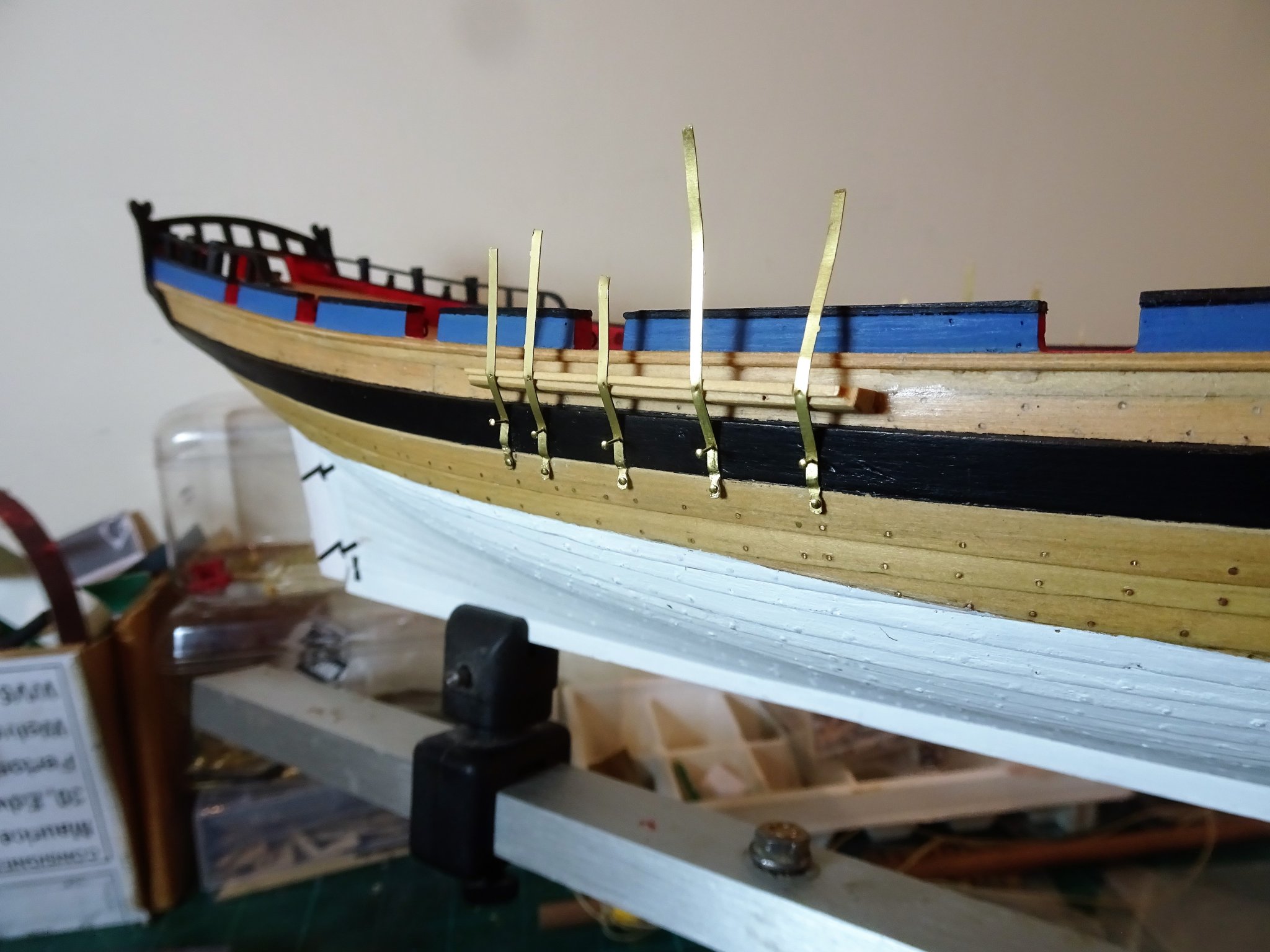
Post 42 Channels. The kit provides clean laser cut channels which correlate to the scale plan* drawings in the Alert Book with the Deadeye spacing to match. They take the form of a traditional Channel arrangement incorporating what would be a strip securing the Deadeye Chainplates in slots along the Channel. However, because of my experience with Cheerful I am aware of a different style of channel on cutters which is a narrower, deeper section, wedge shaped channel with the Chainplates supported in shallow slots, without a covering board. *Confusingly some of the drawings in the Alert book would suggest this simpler form, as does the book cover illustration, whereas the plan drawings show the kit style arrangement. The model of the Hawke also shows the kit style arrangement, whereas the painting by Joseph Marshall of the Alert model shows the other style. Looking too deeply into such matters can seriously affect your sanity so I guess it’s a case of you pays your money and takes your choice.🤔 I have decided to fit a modified version cut from some 4mm Boxwood sheet, and as the channels are to be unpainted, use of Boxwood will match the hull planking. 3716 Working the Channels. Before permanently fitting the channels it is worthwhile checking how the chain plates will fit along the hull. Having made the channels these are pinned into the hull without gluing so that the position of the plates can be checked. 3709 Don’t want any late surprises of shrouds fouling gun ports. 3702(2) Fitting the plates is not quite as simple as it may seem as the bottom end of the plate is pinned immediately below the wale, follows the profile of the wale, (where it is also pinned) then angles outwards up to the channel where it is either pinned in shallow slots or fitted thro’ the slots on the channel if using the kit arrangement. The provided etched chainplates and deadeye rings are nicely done, but I decided to make my own in the manner of the Cheerful build. 3720(2) I am using 1.5 x 0.25mm Brass fret which equates to a 3¾” wide plate somewhat narrower than the kit version. 3728 Test fitting a Chainplate. At this point I have drilled thro’ for the bolt below the wale, but I can’t further advance them until I have made the deadeye strops. On the subject of deadeyes Steel gives the diameter of the Deadeyes as 12” (for a 200-ton cutter) which scales to 4.76mm. 3723 Kit deadeyes often exceed the given nominal size by up to 0.3 mm as is the case with this kit, but they are very nicely made and finished with none of the misplaced holes you often get in a proportion of kit provided deadeyes. Coupled with the provided Channels and etched Chainplates they do provide the oob builder with a straightforward and effective method of dealing with what can be a tricky area of a build. 3722(2) My preference is to use Boxwood versions at a nominal 4mm (4.3mm) which with the built-in excess come closer to the given diameter than the provided 5mm (5.4mm) versions. Strop and plate making will be engaging me for the next couple of days. B.E. 01/12/2019
.thumb.JPG.c26c794447aa42cb53376c07d26b1142.JPG)
.thumb.JPG.fc75af8f5623be2b7e7d45e0ab59f1c2.JPG)
.thumb.JPG.a0e03c9380f63abe8f81c7e224dfd1ca.JPG)

- 335 replies
-
- 17
-
-
- alert
- vanguard models
- (and 1 more)
-
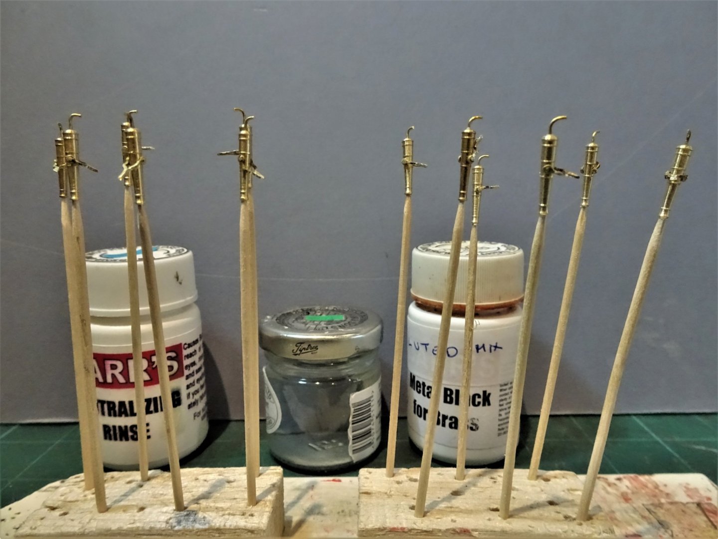
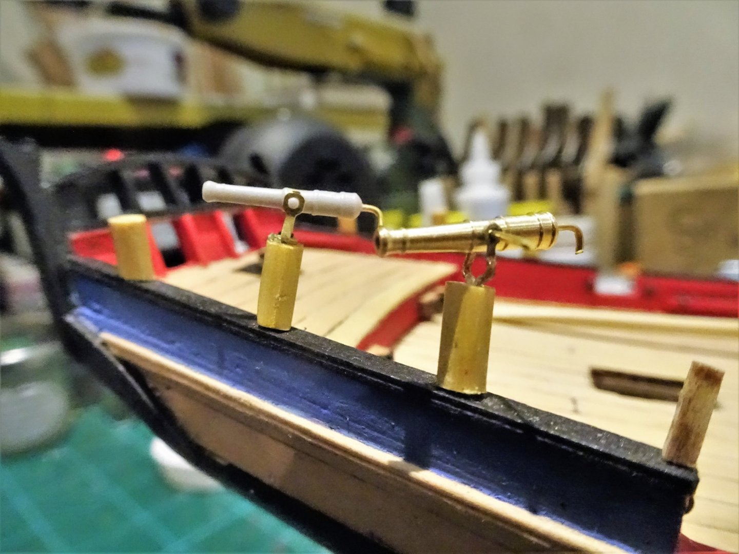
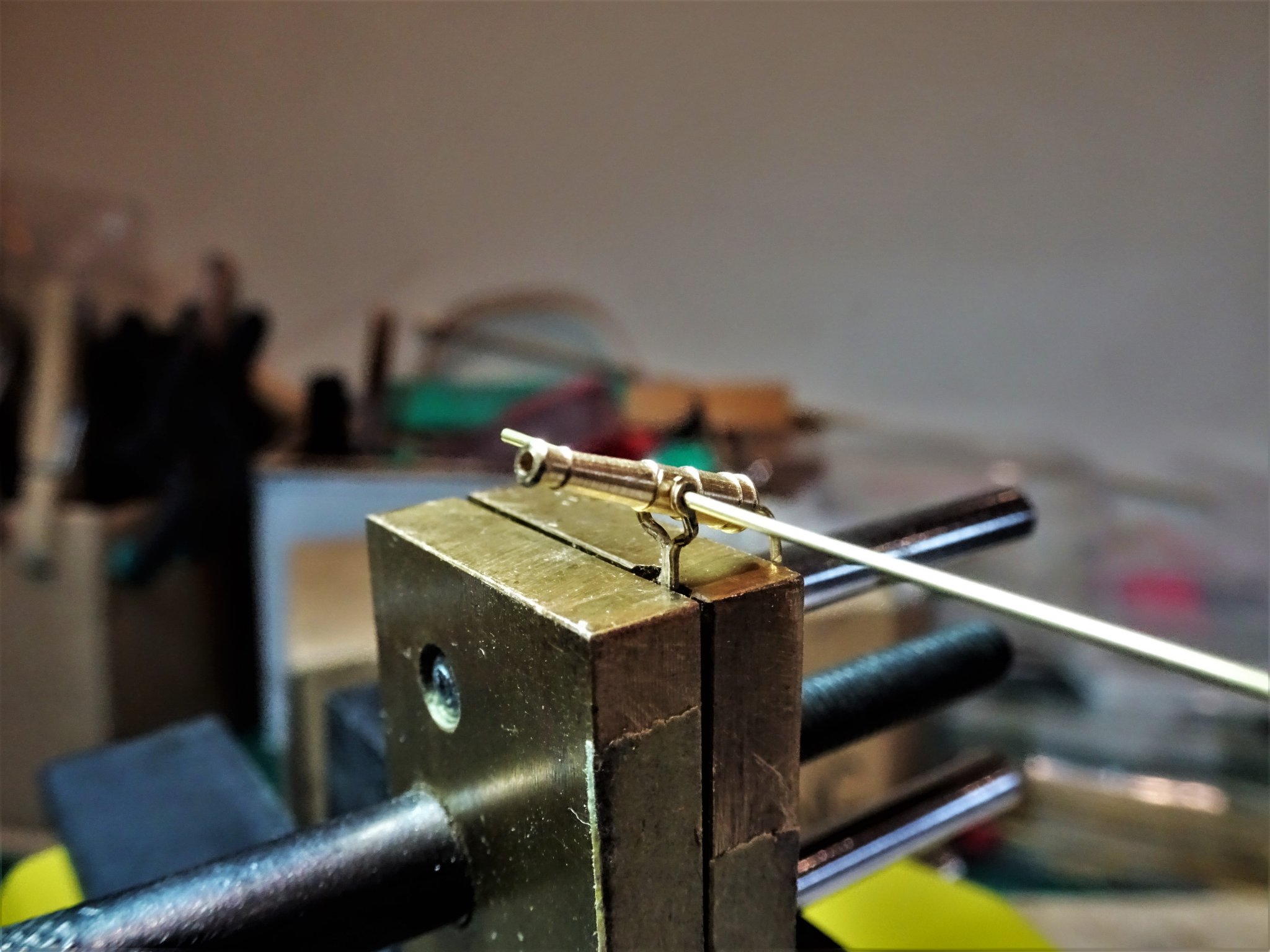
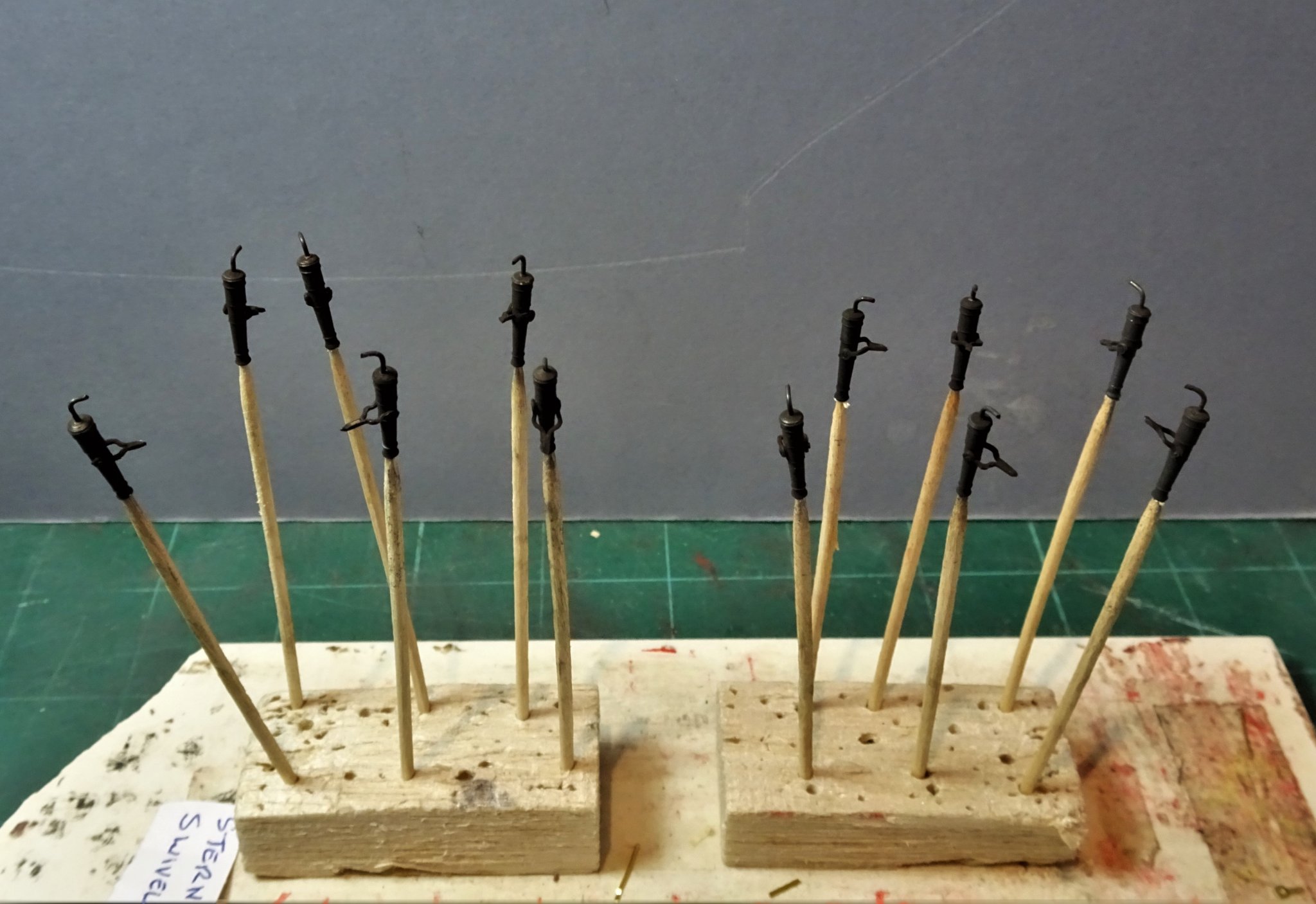
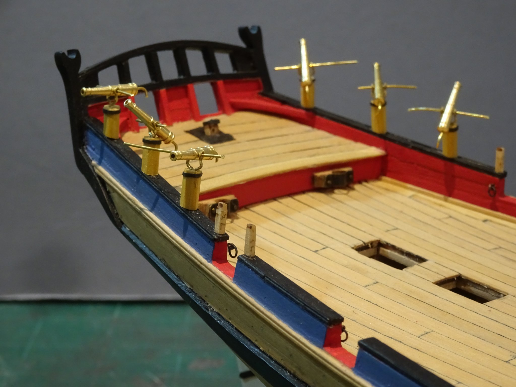
Thank you Christian, I rather think it is Chris who has reproduced those wonderful lines in the design of his kit.🙂 Post 41 Completing the Swivels None of the kit parts were used in the production of the Swivel guns. I have the remaining six bow guns to complete and then blacken the set of twelve. 3672(2) The crutches in their raw state. 3676 Bringing crutch and gun together. 3678 Cleaned and ready to blacken. 3683 A few dips later and the guns are ready to seal. 3685(2) For the ball on the end of the handle I use my old standby of pva. This is very useful for creating such features where other methods are impracticable. I also use it for such things as handles on gun quoins, and bolt heads on metal straps at small scales. 3704(2) 3691(2) 3688(2) 3694(2) 3698(2) The ordnance is now completed and will be put aside until final fitting. Moving back to the hull where another puzzlement arises. B.E. 28/11/2019
.thumb.JPG.0e78f6979591a86f0409728ca1a387da.JPG)


.thumb.JPG.a18b593f9bb6ad5d4d2c476f2cf4ca37.JPG)
.thumb.JPG.0686972486a74c01deb192c19e1f84c0.JPG)
.thumb.JPG.37542f7753b17fec4757aaef6aedadc6.JPG)
.thumb.JPG.7cca717dc342400c2606e22acc6055e2.JPG)
.thumb.JPG.597a1728578b9841f576c19790b4a1f2.JPG)
.thumb.JPG.3882bab43dabbd3d27d87ff93a16894c.JPG)
- 335 replies
-
- 22
-
-
- alert
- vanguard models
- (and 1 more)
-
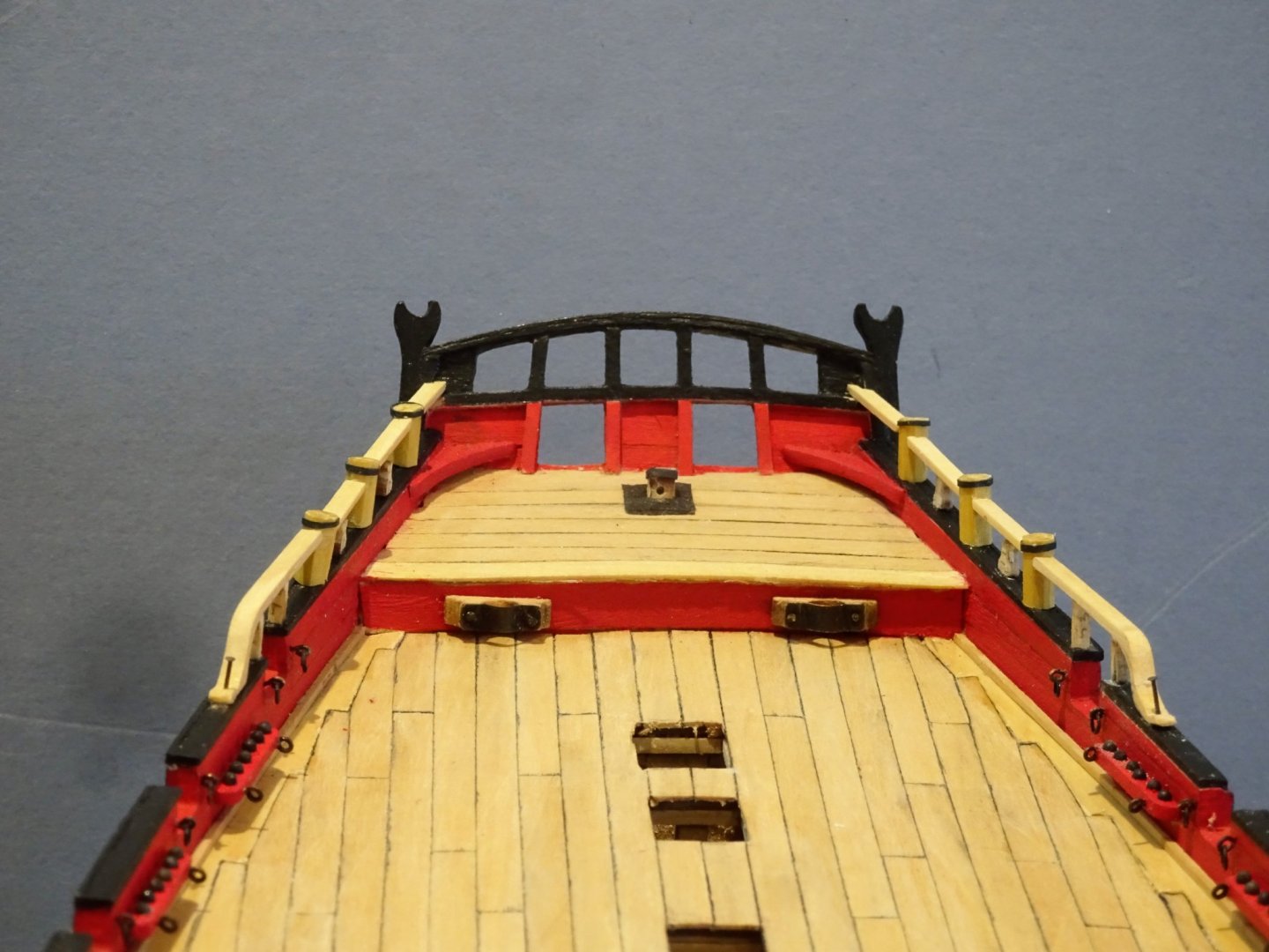
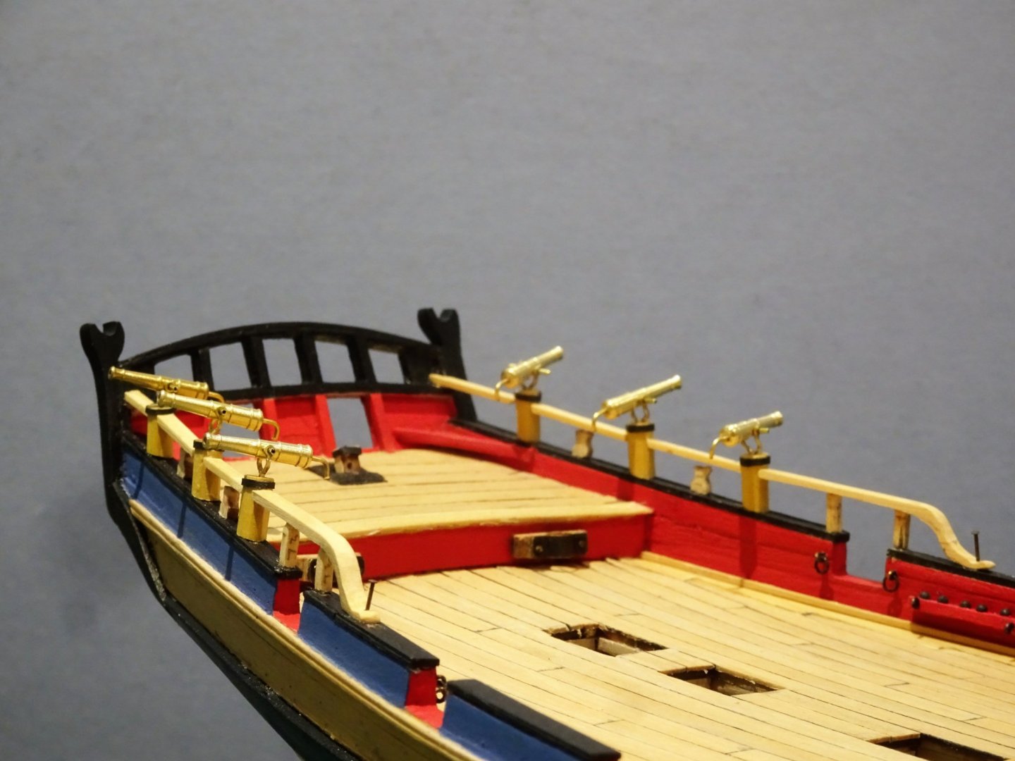
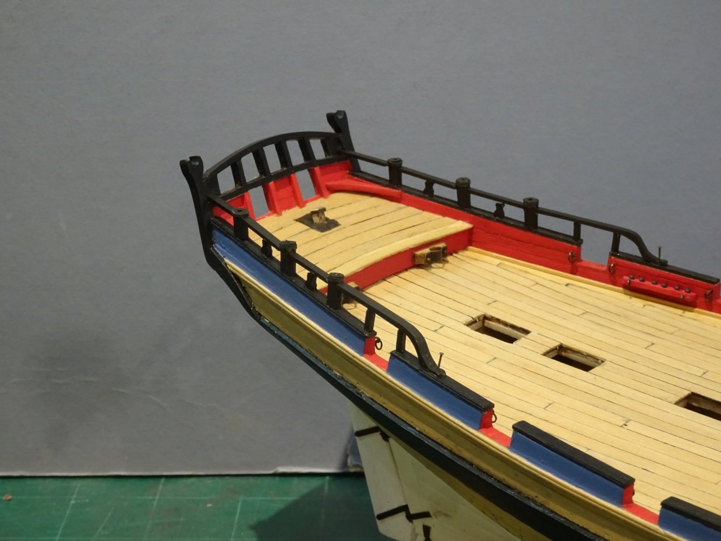
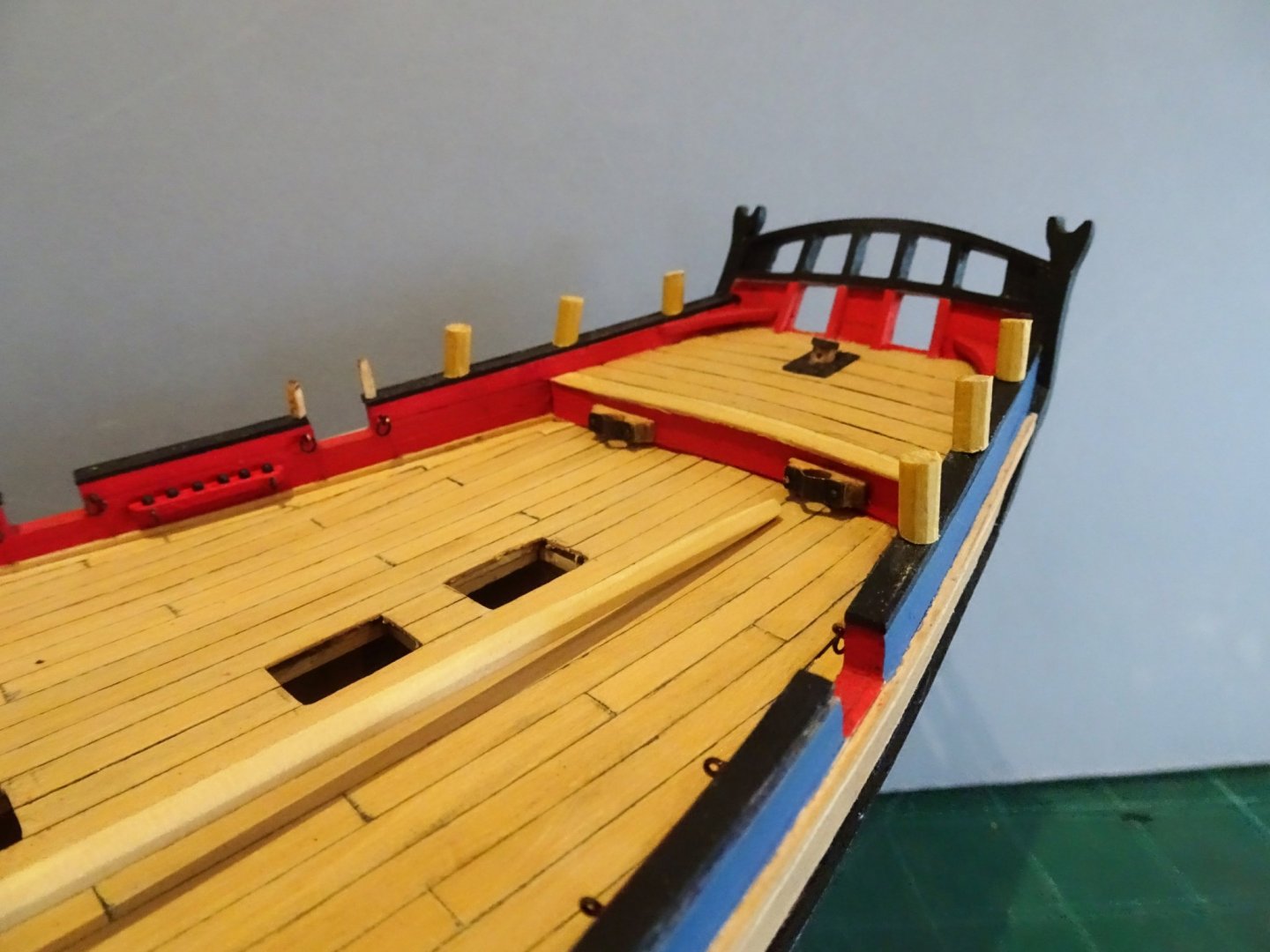
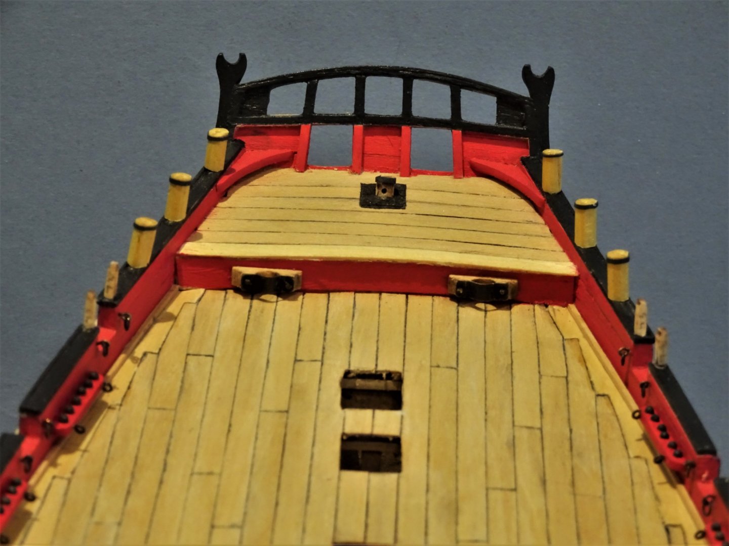
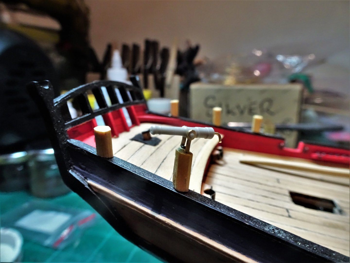
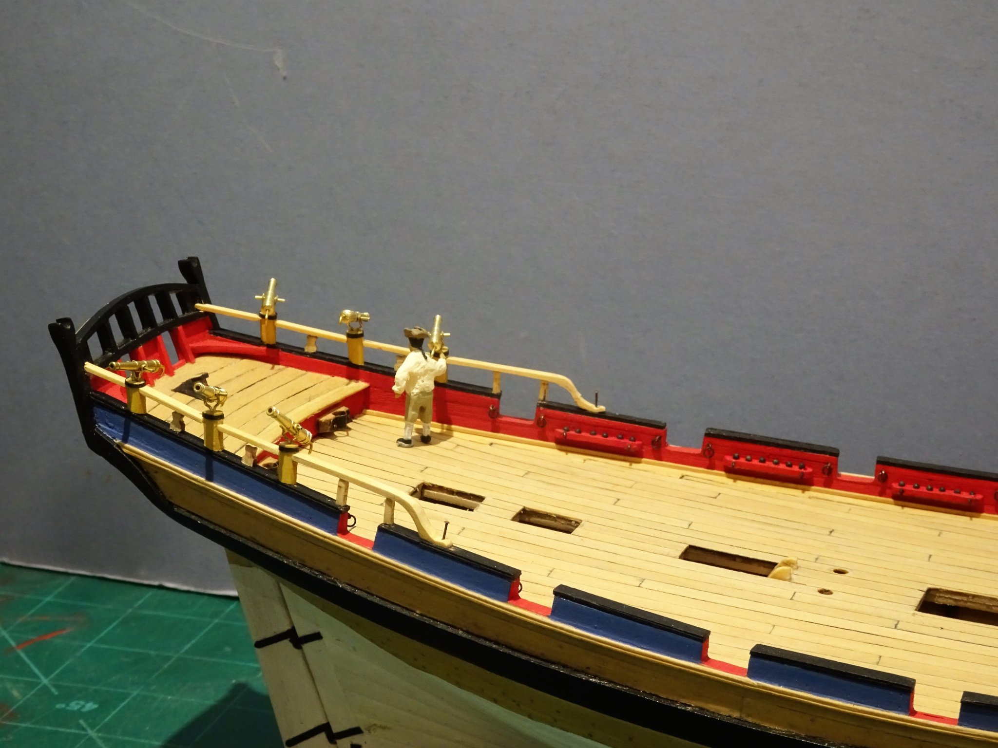
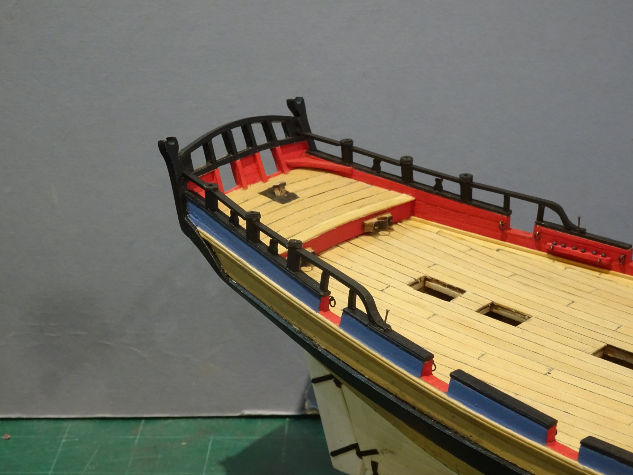
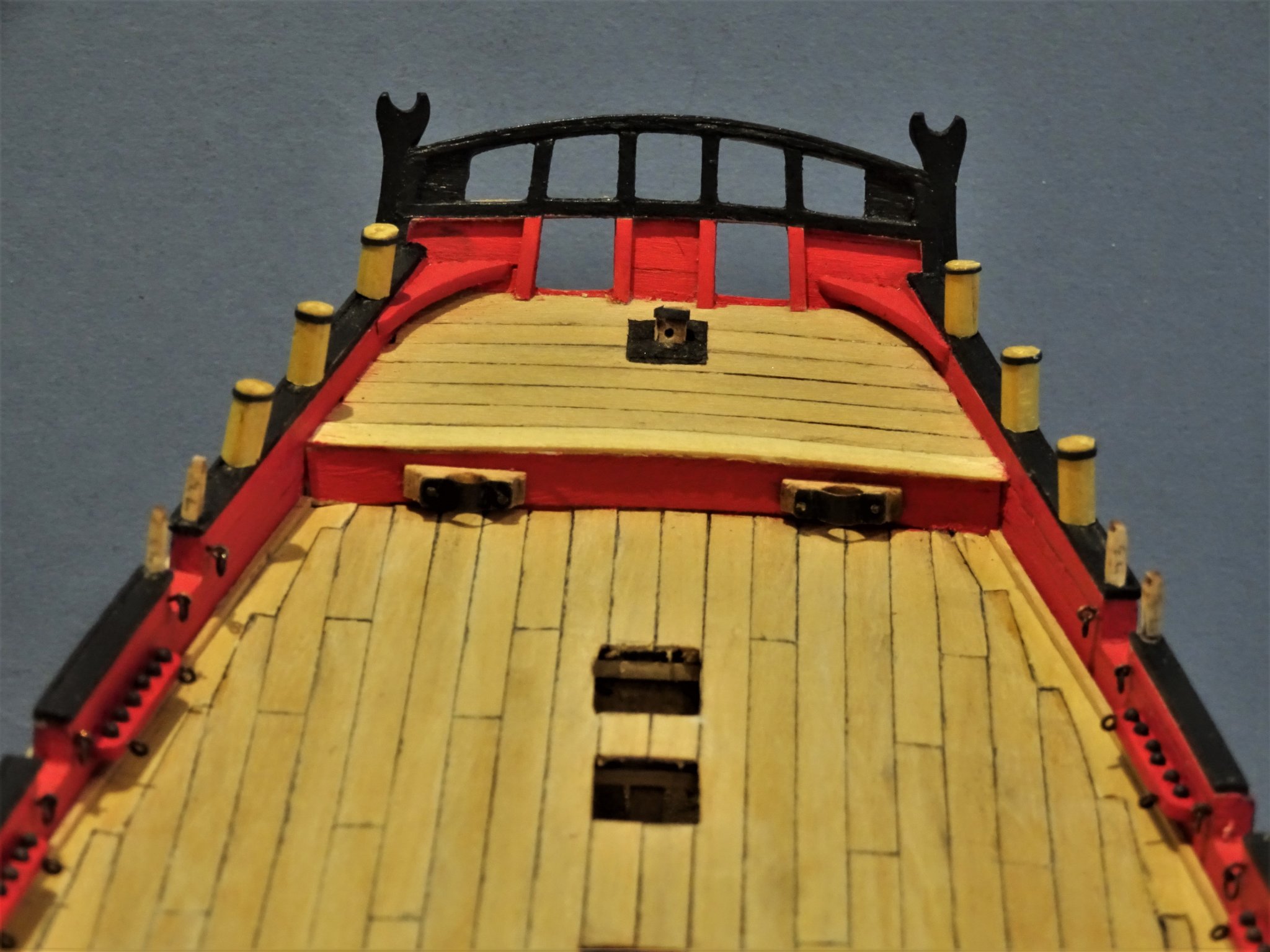
Post 40 Rough Tree Rails This involved more than a little trial and error. Each section had to be independently fitted between the Swivel posts, whilst hopefully maintaining an even run of the rail. Before I started I both pinned and glued the Finger and Thumb timberheads between the posts; I used the kit provided items. The forward end of the rail ends in a curved hance. This was fashioned from some 2mm Boxwood Sheet and cut out on the scroll saw. 3628 3630 Went a little easier than I thought it would be. 3638 A re-check of the swivel fit. 3650 Lemuel my Helmsman assists with a scale check. 3657 Whilst I was on a roll I continued to complete the Timberheads and swivel post at the bow. I used the kit provided Timberheads (Finger and Thumb) as they are nicely shaped and good for scale. As they are to be painted I didn’t think it worth the effort to reproduce in Boxwood. 3654 The provided Swivel pedestals, rectangular affairs, I replaced with Boxwood Octagonal versions. The measurement I took from the Alert Book. 3669 3665(2) 3666 3664 B.E. 25/11/2019

.thumb.JPG.6fdaaa9cc3c2cdddd02d8607cf6a27e0.JPG)
- 335 replies
-
- 26
-
-
- alert
- vanguard models
- (and 1 more)
-
That looks to be an interesting site. In the UK the smallest eyebolts I have found are these: www.jotika-ltd.com/Pages/1024768/Fittings/83505.htm I use them extensively in my builds. B.E. PS. The link doesn't seem to be active, The Company is Jotika who manufacture Caldercraft kits. I am referring to mini brass etched eyebolts sold in sets of 250.
-
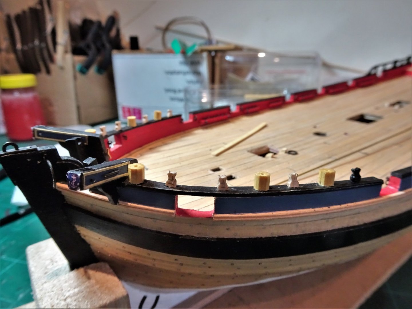
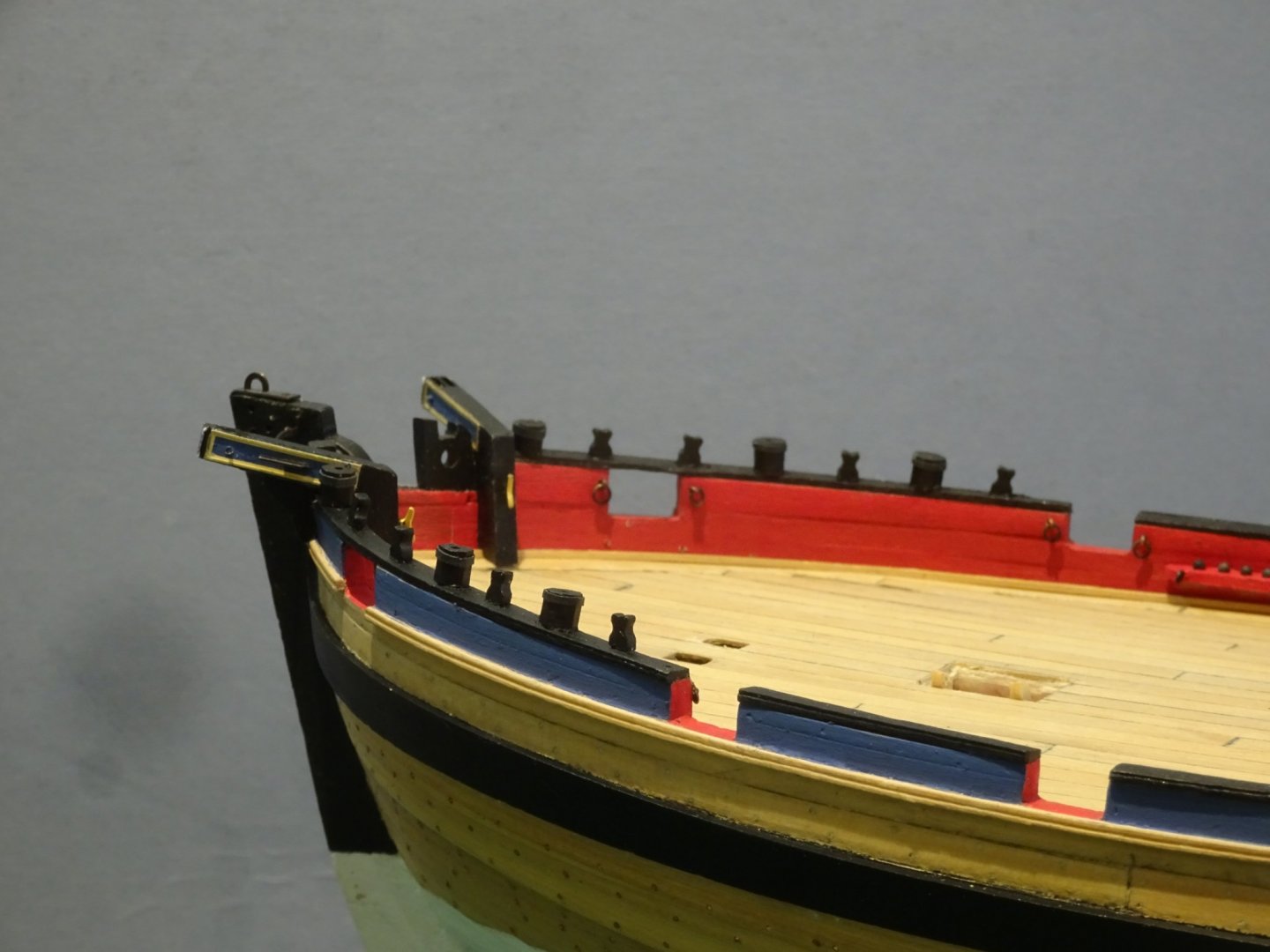
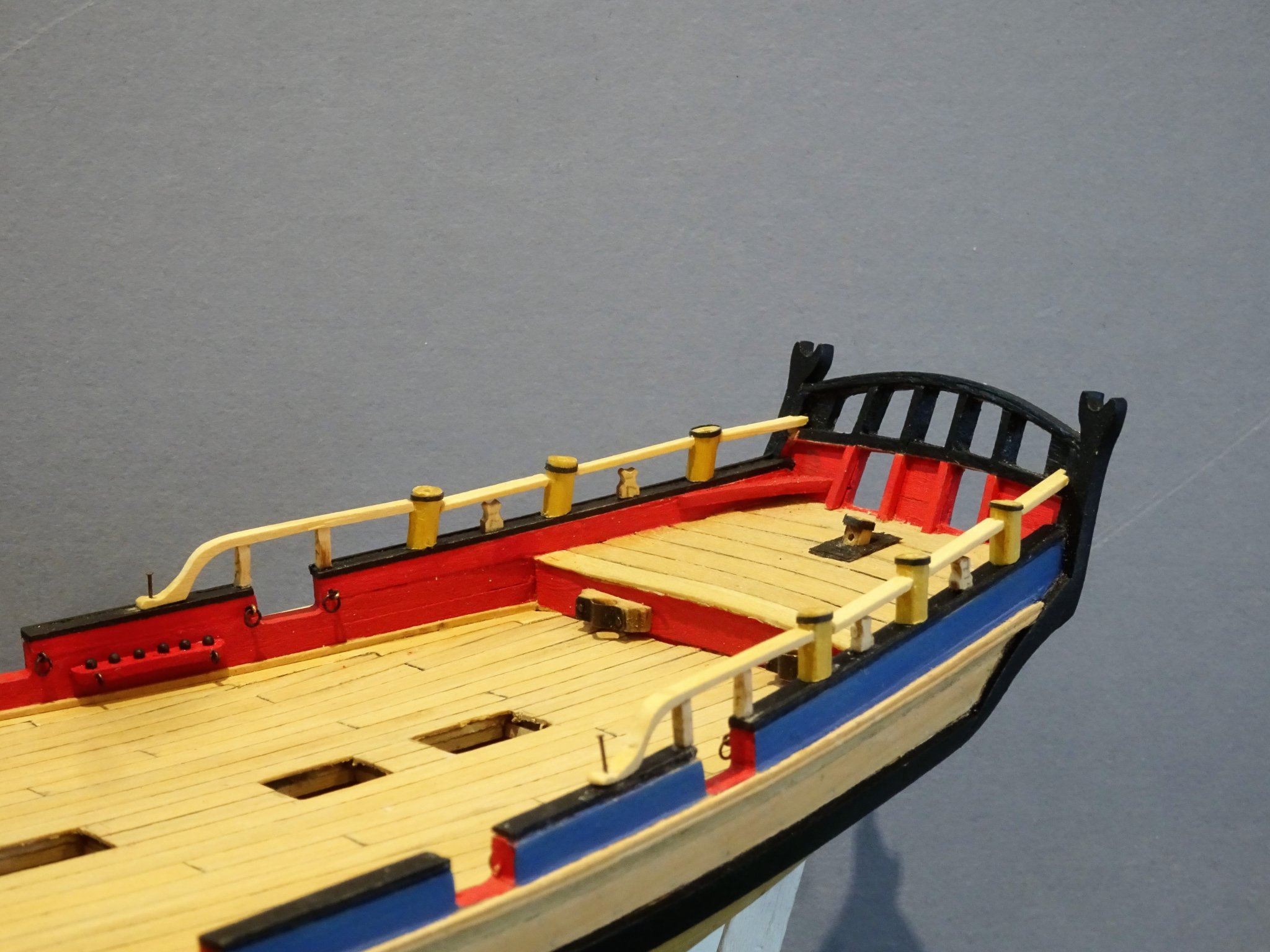
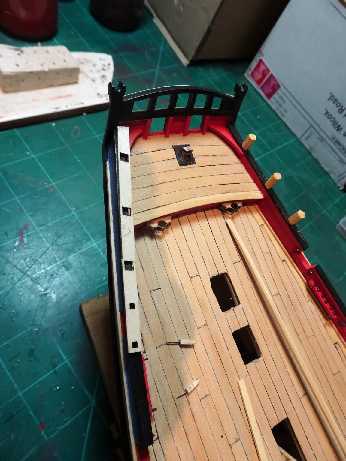
Post 39 Rails and Swivel Gun pedestals This is the last main hull construction job outstanding. The kit provides a pre-formed Rough tree rails with the slots for the pedestals and timberheads pre-cut. 3550 I used the provided rail as a template to mark the positions of the posts and timberheads. The kit part is perfectly fine as a simplified arrangement, but the rail of necessity is too wide, as it is designed to allow the Swivel gun pedestals to run thro’ it. Both the Alert book and the Admiralty plan show the typical octagonal shape applicable to such pedestals, and a narrow Rough Tree rail that runs thro’ them, or tenons into them. The pedestal bottoms are angled as they run down the drift rail with the tops horizontal. 3548 I made the octagonal pedestals from Boxwood Square stuff and used a simple jig to cut the angles using the kit parts as a template. 3580 With the Swivel crutches made the holes can now be drilled to take mountings. At this point I have glued the posts into place as I need a solid base to fit the swivels and more importantly the Rough Tree rail. 3586 Testing the fit of the swivel guns and mounts. Since the previous post I have re-visited the Swivel mounts and made them slightly smaller. That is the easy bit. More tricky is the fitting of the Rough tree rail running between the posts and topping the Timberheads each side of the port before ending in a hance on the Drift rail. For the Rough Tree rail I planed down a 1x4mm Boxwood strip supplied in the kit, until it was 2.0mm wide. I am then faced with the problem of how to fit between the swivel posts. Mortise them in perhaps or pin them; the main issue is keeping a smooth transition between the posts. I will report on how it goes in my next post. B.E. 23/11/2019


- 335 replies
-
- 20
-
-
- alert
- vanguard models
- (and 1 more)
-
I'm sure you will enjoy the Alert kit Phil, it has a lot to offer both novice and kit basher, and Chris's decision to upgrade the guns in the newer editions, goes a long way to improve the basic kit. I look forward to seeing your approach. Cheers, B.E.
-
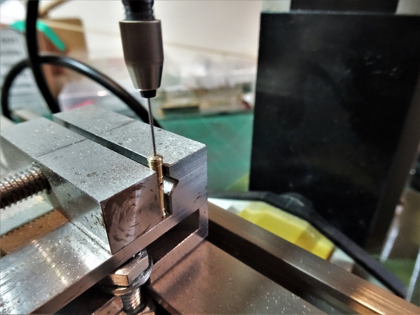
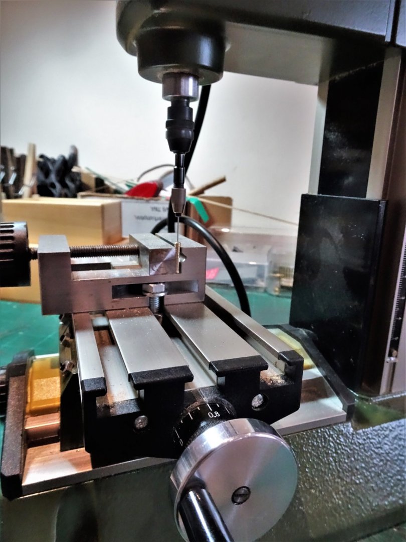
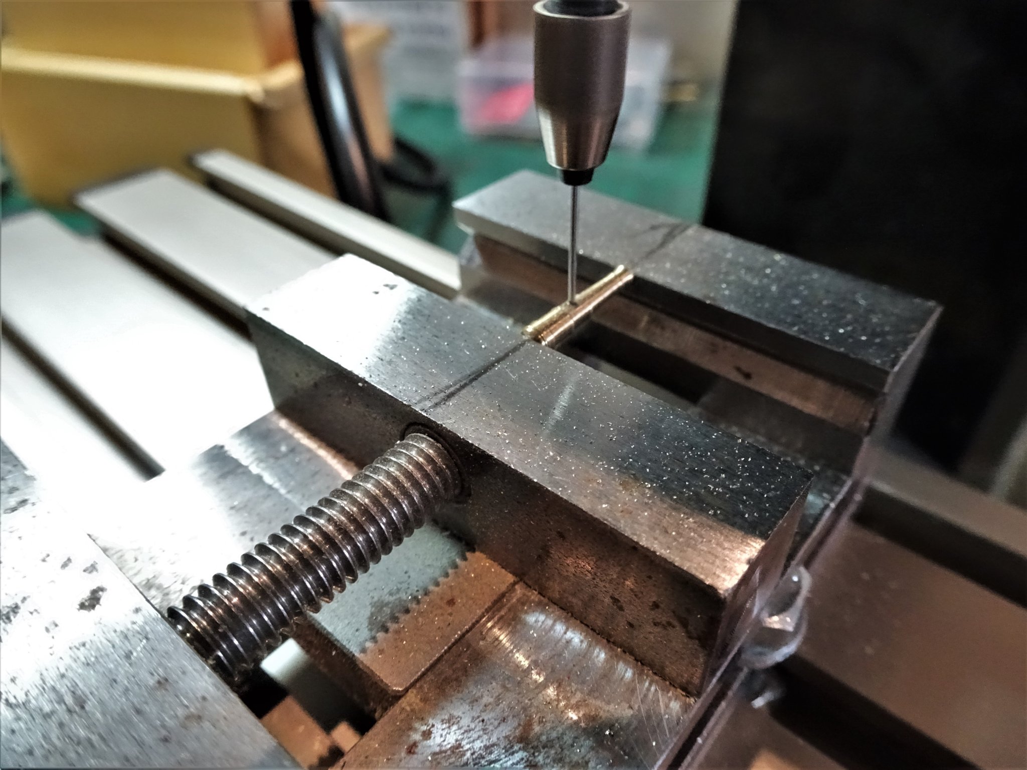
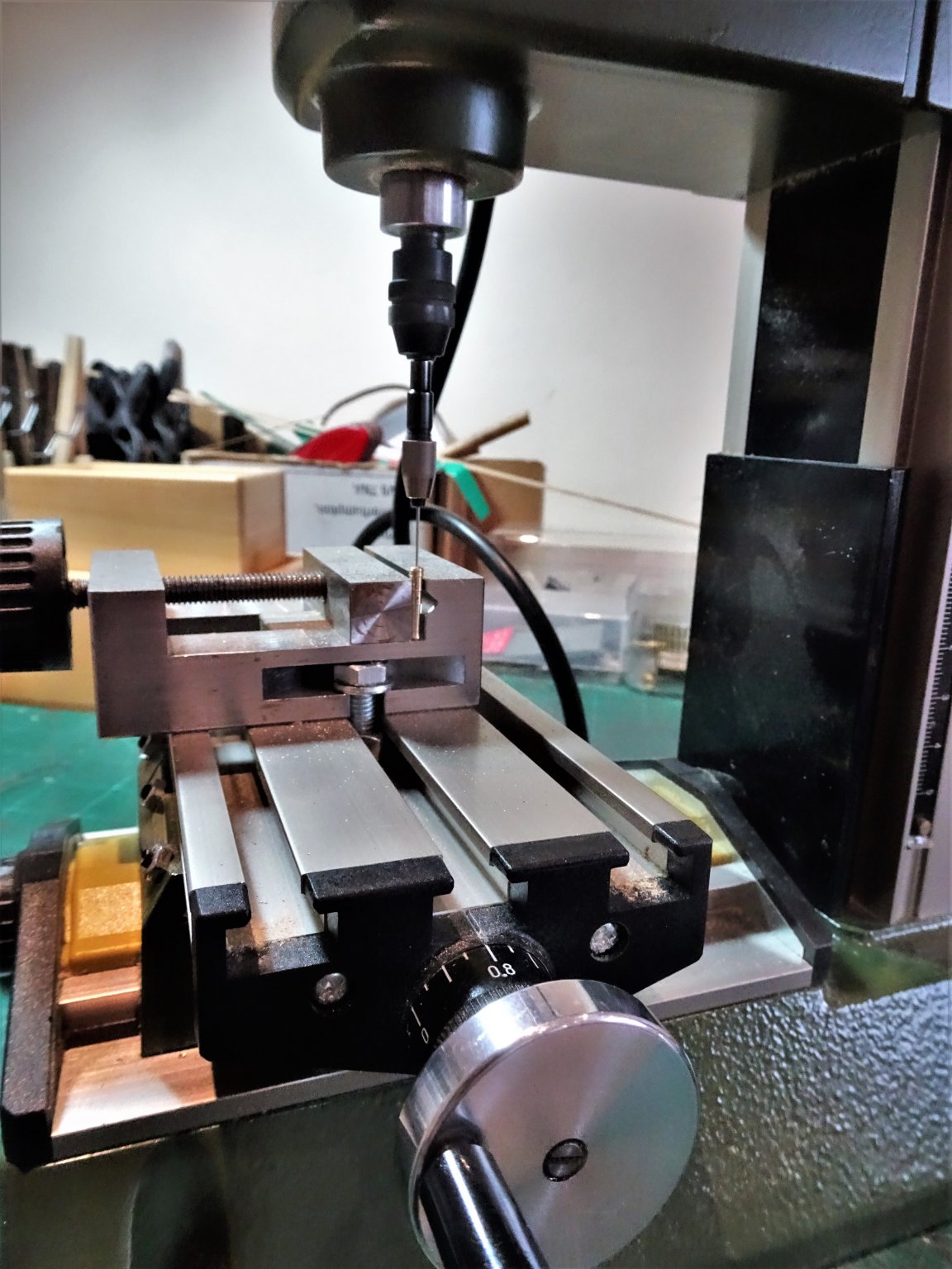
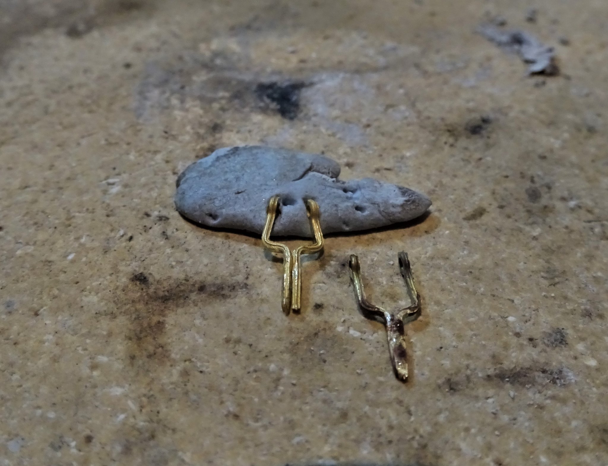
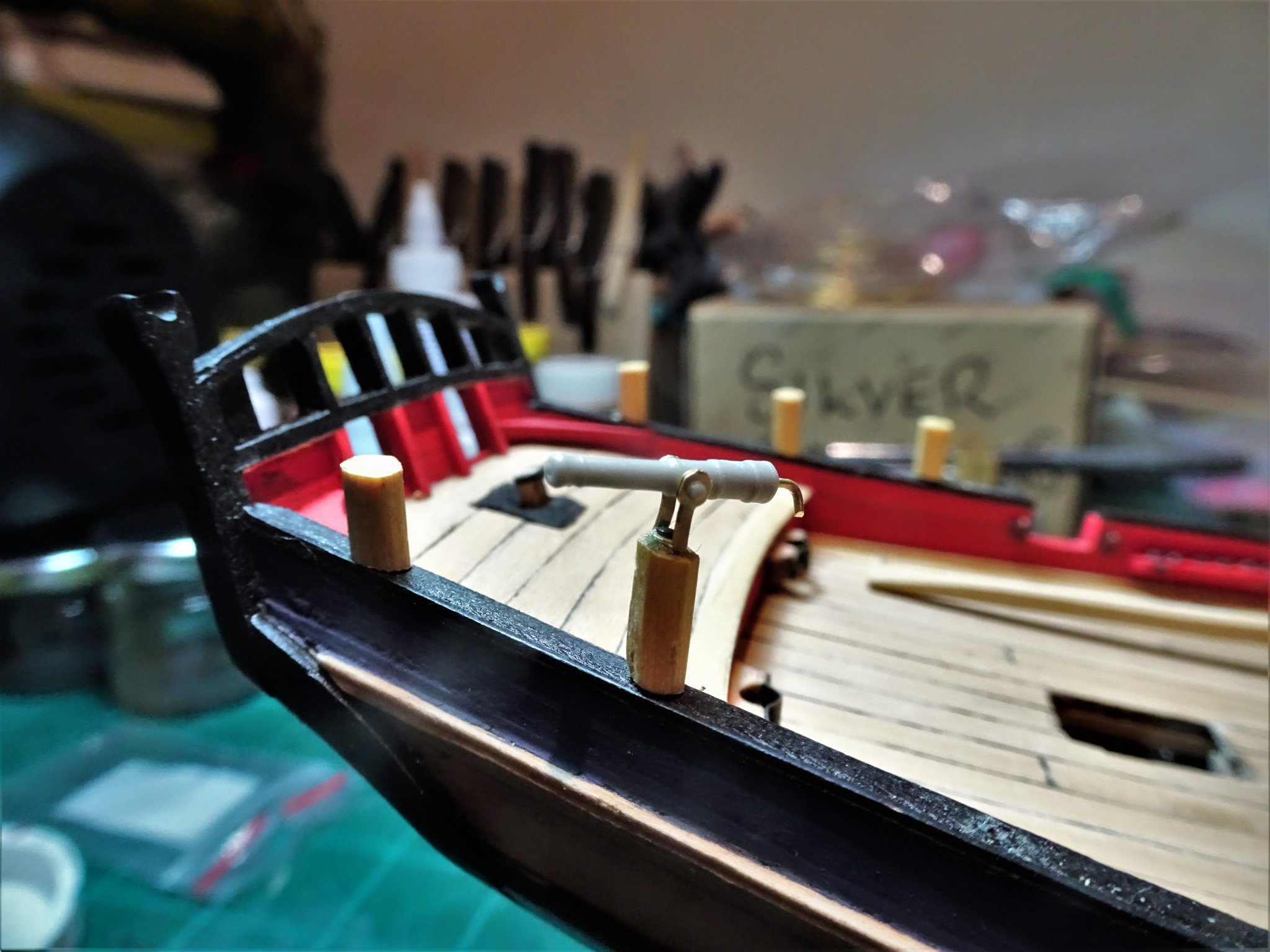
Cheers Alan, I've no immediate pressure to complete the guns so I can ponder the subject a while longer.🙂 Post 38 Swivel guns I had started making the Swivel gun pedestals but have side stepped to look at the Swivel guns and their ‘iron’ yolks that fit into the posts. For the Swivels I am using RB 15mm Brass guns which are spot on for scale. 3558 They do need a little fettling because for some odd reason the trunnion hole doesn’t go all the way through the Barrels, but at least only completing the drilling is involved. 3560 The button also has to be removed and the gun drilled to take the tiller. 3561 A mornings work on the little Miller and it’s all done. 3568 The kit provides neat photo etched Swivel Gun yolks which save a lot of time fiddling around making these small fittings, a boon to those modellers less inclined to indulge in habitual kit bashing. The photo shows a mock-up of one of the early Resin Swivel guns. However, I decided to make my own yolks using the method I used on my Pegasus build. 3564 As with the last time I made these items they were formed from etched brass hooks but this time I silver soldered the two halves to form the yolk. 3570 The wip RB gun alongside the Resin Kit version. 3573 I do prefer the crispness of a brass gun, and personally I don’t think you can beat the look of a chemically blackened gun. With the Yolks made I can now return to looking at the posts and drill out to take the mounting. B.E. 21/11/2019


- 335 replies
-
- 20
-
-
- alert
- vanguard models
- (and 1 more)
-
An interesting project, and great approach to the start, Christian. I look forward to seeing her progress. B.E.
-
The smallest guns I have rigged were on my 1:150 scale Heller French 74 build. The carriages were around 8mm long. It is probably feasible to add the Breeching ropes if desired, but the side tackles are very tiny and 'false' representations are the way to go, I suppose it depends on how much you wish to torture yourself. 😉 I used a combination of very fine wire and tiny sections of styrene for the blocks. B.E.
-
Hi Alan, The Cap Squares that retain the gun trunnions on the carriage are hinged and secured at the forward end by a pin thro' a bolt over which the Cap Square fits. The pin has a short chain attached which is secured to the carriage side. You can see the arrangement here on one of the Quarterdeck 12 pounders on Victory. Cheers, B.E.

- 335 replies
-
- 5
-
-
- alert
- vanguard models
- (and 1 more)
-
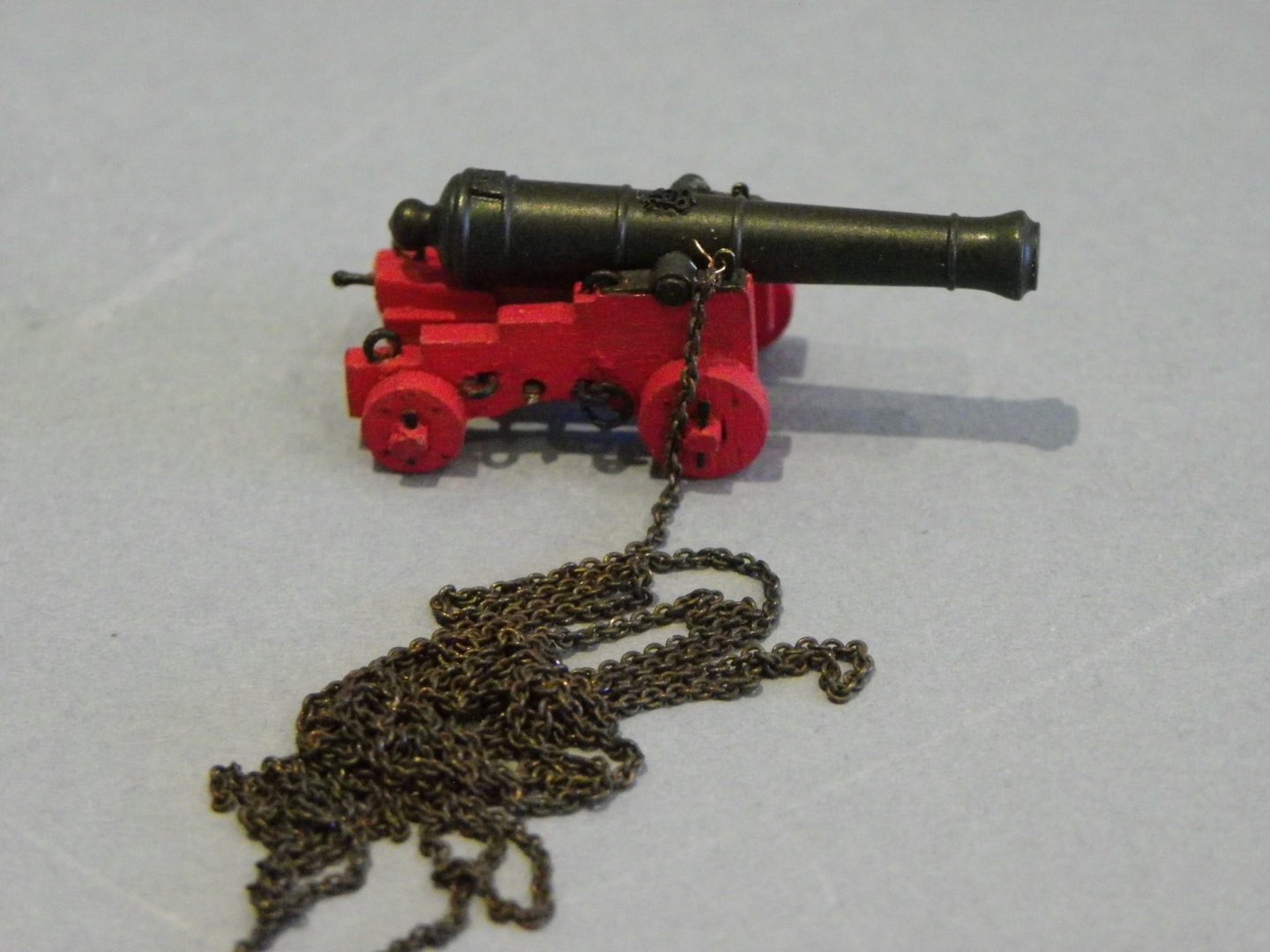
Post 37 Completing the Guns This is now the time to secure the gun barrels to the carriages using the Cap squares. These are supplied as etched items and do have the fold lines and hole points marked to take the retaining bolt and Cap square hinge. 0020(2) In preparing the Cap squares I use a trunnion bar as a jig to aid the folding process. 0019(2) Once formed the holes are drilled thro’ and the ends trimmed a little to better fit the carriage. 0029(2) The Cap squares are quite fragile with weakness at the bend points; there are only a couple of spares so careful handling is required. Fitting Cap Squares is a tedious business; I use ca to secure to the top of the carriage and then drill thro’ to take the retaining bolt and hinge. 3521(2) These little additions are not referred to in the instructions, but I like to add them. 3531(2) I use tweaked etched eyes from some stuff I have lying about and copper eye pins. Once in place these help to better secure the Cap Squares. 0075 Still thinking about adding the bolt pins and chains to the carriages as I did with Cheerful. The smallest chain I have is 48 links to the inch which may be a tad over scale. I’ll leave the guns for now and go back to a little woodwork. B.E. 18/11/2019
.thumb.JPG.00dfbd6333bbb7674190fbcbbc80ba1a.JPG)
.thumb.JPG.92ced095e928a42472a6dd3a63d19e33.JPG)
.thumb.JPG.ebc2461d751dcda810f0e54c301ec1e2.JPG)
.thumb.JPG.cfcaeebe1934adcfc18cc1989c5d63bc.JPG)
.thumb.JPG.62f17eef768884957522a30ad390a0be.JPG)
- 335 replies
-
- 18
-
-
- alert
- vanguard models
- (and 1 more)
-
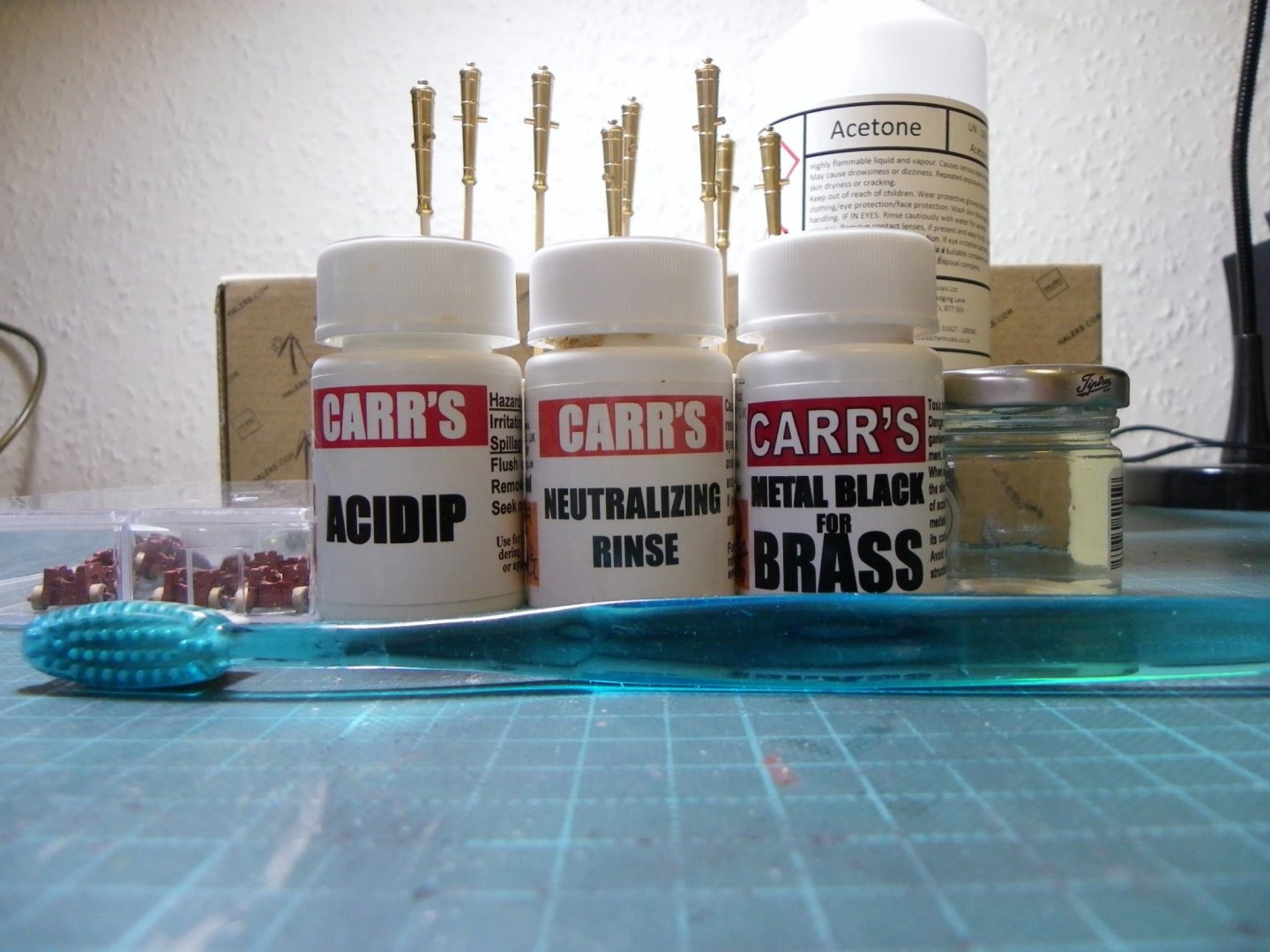
Hi Jim, thanks for looking in. This is my approach to metal blackening. My Blackening Kit 1) I first scrub the guns in water with washing up liquid using an old toothbrush. 2) Rinse the guns in de-ionised water. 3) Soak the guns in the Acid Dip for a couple of minutes, and then rinse in the Neutralising fluid, but I find the de-ionised water is just as good. 4) Immerse in the blackening fluid (which I dilute with de-ionised water by around sixty percent) until the guns are black. 5) Rinse again. 6) Dry using a hair dryer on full heat. 7) Buff the guns using a soft paintbrush to check the coverage. Because I have used ca to fix the Monograms invariably this will show up, requiring scraping away in places and the careful use of acetone to re-clean the area. Acetone dissolves ca so great care must be taken not to lift the Monograms. 9) I re-dipped the Alert guns several times until I got the finish I was after. 10) With an even black surface I used Humbrol Matt Cote thinned a little with White Spirit to improve the flow, to paint over the guns. I don't always coat the guns, I didn't with the guns on my Cheerful build, but they were larger and handling was easier with less risk of marring the surface. Hope this helps. B.E. 18/11/2019
- 335 replies
-
- 4
-
-
- alert
- vanguard models
- (and 1 more)
-
You may find this little book very useful for modelling the 1:180 Airfix Victory. HMS Victory(Classic Ships No 1: Their History and how to model them) Noel C L Hackney. It specifically relates to improving and rigging this particular kit and dates from the 1970’s. Second hand copies can be obtained very cheaply, I see there is one on Abe Books for the price of £1.98 at present. Well worth a punt😊 Cheers, B.E.
-
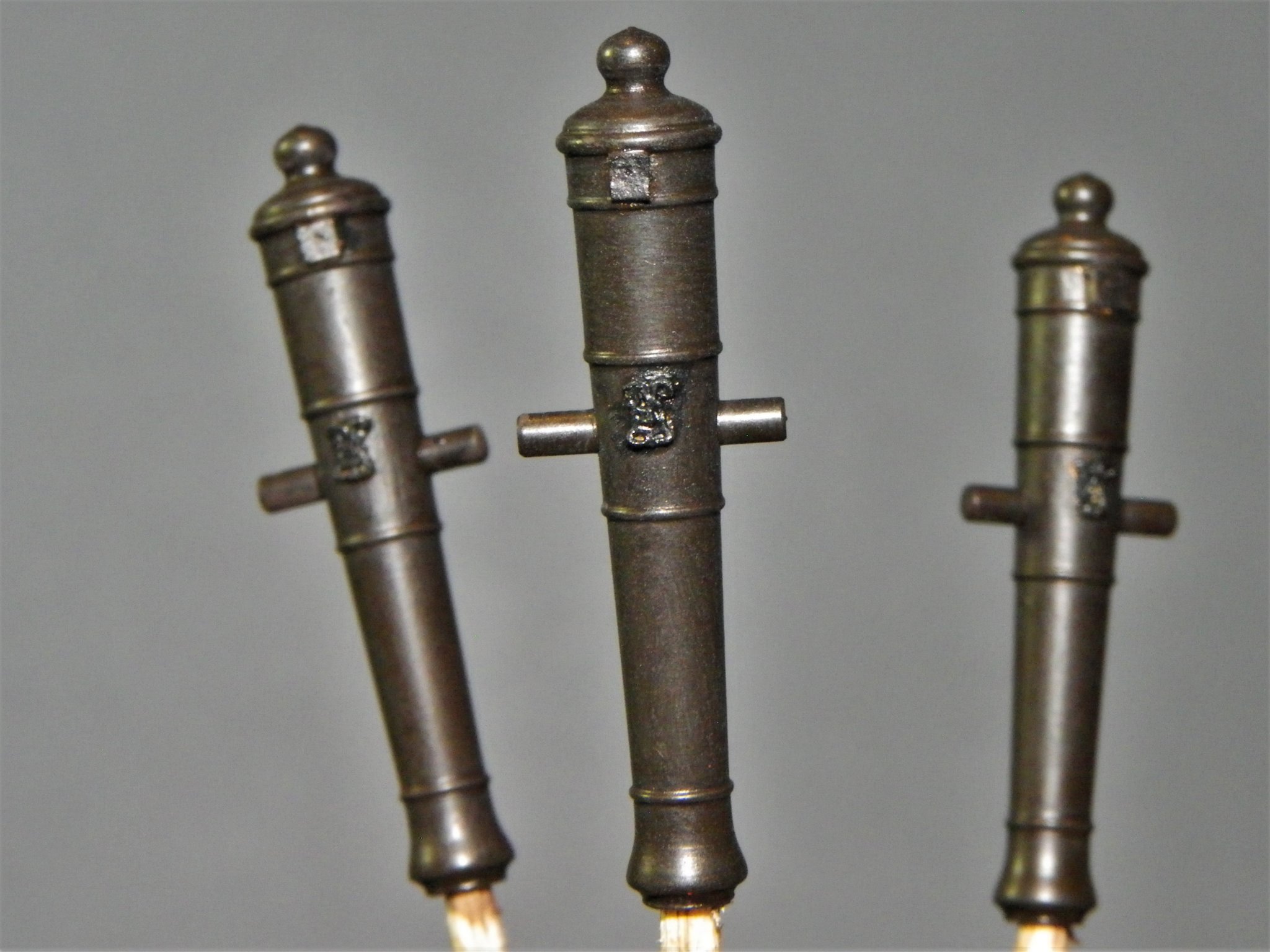
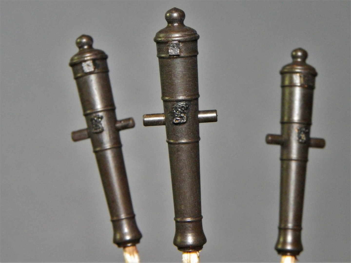
Post 36 Preparing the Guns. I have replaced the kit provided guns with RB Brass versions. To these the Royal Monograms (Syren) and representations of the vent holes are added. The Monograms are exceptionally fragile items and there is quite a high attrition rate. Even so once stuck they will withstand the acid dip and the blackening fluid. 0003 I used the smallest of the Syren Monograms. Once the gun is thoroughly cleaned the Monograms and vents were added. A tiny spot of thick ca is applied to the gun and the monogram gently pressed into place. 0044 This flash shot shows up the Monograms but is not a true reflection of the colour. 0039(2) This shot more closely reflects the colour. It takes several re-dips following cleaning off any residual ca to get the desired finish, and from this point plastic gloves are worn when handling the guns. 3497(2) I don’t buff the surface but seal it using slightly thinned Humbrol Matt Cote, this both protects and deepens the colour a little. So, here’s the completed set. 3500 3503 3505 3506 3501(2) 3498 It has taken about five days’ work to reach this point, but I consider taking extra time with the guns is well worth the effort. On an open decked vessel such as a cutter they are a major feature and very exposed to view. In my next post I will be covering the combining of guns and carriages and adding the fine detail. B.E. 16/11/2019
.thumb.JPG.694a8887896eed2f408a6478592673bf.JPG)
.thumb.JPG.6b4b30685539c1a5460dcc1590d33444.JPG)


.thumb.JPG.3dd770809f3e4432304527801301c962.JPG)
.thumb.JPG.a78dfca89306f8392556dc13698510a4.JPG)
- 335 replies
-
- 25
-
-
- alert
- vanguard models
- (and 1 more)
.JPG.4312eae721827b594598648081521404.JPG)
.JPG.04415009ff5cb2e61d87cdded0b87daf.JPG)
.JPG.7a39536256ef6ed234731dbe05dfa8c9.JPG)

.JPG.e14426ab50105fdfb2ecf122749f3c9a.JPG)
.JPG.b28b980ca875e984c1d0cf1ca4f10fde.JPG)

.JPG.32905ec80713d0b4a538e1fb3964b415.JPG)
.JPG.2f57f17f3fc688ab107341524a73f28d.JPG)


.JPG.6198815f90e7f088bf7ec2707c9eda4b.JPG)

.JPG.2176f7c31d4e43423168f98b24103f55.JPG)
.JPG.aae2766025a084e5e07b264d586674f0.JPG)

.JPG.e9a4c6fed1749926905063d0178ffa82.JPG)
.JPG.49962cbf0a86f8e444641f178c995e77.JPG)
.JPG.0e10ef844cacc235db7c5a8055875865.JPG)

.JPG.95a374145ed815a58a471b77636db5e1.JPG)
.JPG.9c9d68bbdc695705d7fb071f548a6c00.JPG)
.JPG.fab3e3eb07f922166c709ca46146ce38.JPG)
.JPG.4fbe9900d9bfcb101d7e85b5d6855024.JPG)
.JPG.efb3131ca921b6c2c0a75fd8abcf3ead.JPG)
.JPG.ee048e21ade8df94a58749d213b90760.JPG)
.JPG.8dec7387fbb3f27d6d8116b33707e4b1.JPG)
.JPG.cc72864cab74f3042e3889f60b8d4fad.JPG)
.JPG.b7c014b5630471b7c94829d5544a2222.JPG)


.JPG.ec04dc7c9e50f2c6fb42fe12ea428875.JPG)
.JPG.b64e77086201f9303efb6f0e93e98f06.JPG)
.JPG.8daa8f65ad8a438cf173d359b214b174.JPG)

.JPG.d40c6d0970b61cc2e45ee41a344adfd9.JPG)
.JPG.a82c9a762fe57f397f9686d53960ace8.JPG)

.JPG.02371e6d572f31d7b4e8e6f39f427cea.JPG)

.JPG.e59ae7e459572b01e316377cc990127f.JPG)
.JPG.91487d7f9b167a8cf3bbaf8c5dbd64a5.JPG)
.JPG.2b40c0aeaee14e56a6fc315e397aa631.JPG)
.JPG.dd9843c11d7909104f8b12e08b208ab5.JPG)
.JPG.fd29a5f71909dc17299e69606965c854.JPG)
.JPG.76e82caff47d59cad21dd1fa2bd2aeda.JPG)


.JPG.3aff6f26837ce46634e029e01535b31f.JPG)


.JPG.dbee50f409d78fd0468d71cfa9bbfa47.JPG)
.JPG.9240c2675f3b1fd4e4d4bb57295a7af7.JPG)
.JPG.f7d444236142fd1a550561402af7df20.JPG)
.JPG.f55865351a12111942448a376b899b0f.JPG)
.JPG.83a9d10e61bd672ba1ba41f7395161c2.JPG)


.JPG.ca021ab8edc23a317cb7896ccda9264e.JPG)


.JPG.65723348b3adfda2aa5d743954e731ff.JPG)
.JPG.701d5ec98f7ef96fed34a0f744c395a3.JPG)
.JPG.5e9fa46cec943a25b25a1768feffbb10.JPG)