.JPG.ca33079f5815b861e67b9c2cccd37982.JPG)

Blue Ensign
-
Posts
4,571 -
Joined
-
Last visited
Content Type
Profiles
Forums
Gallery
Events
Everything posted by Blue Ensign
-
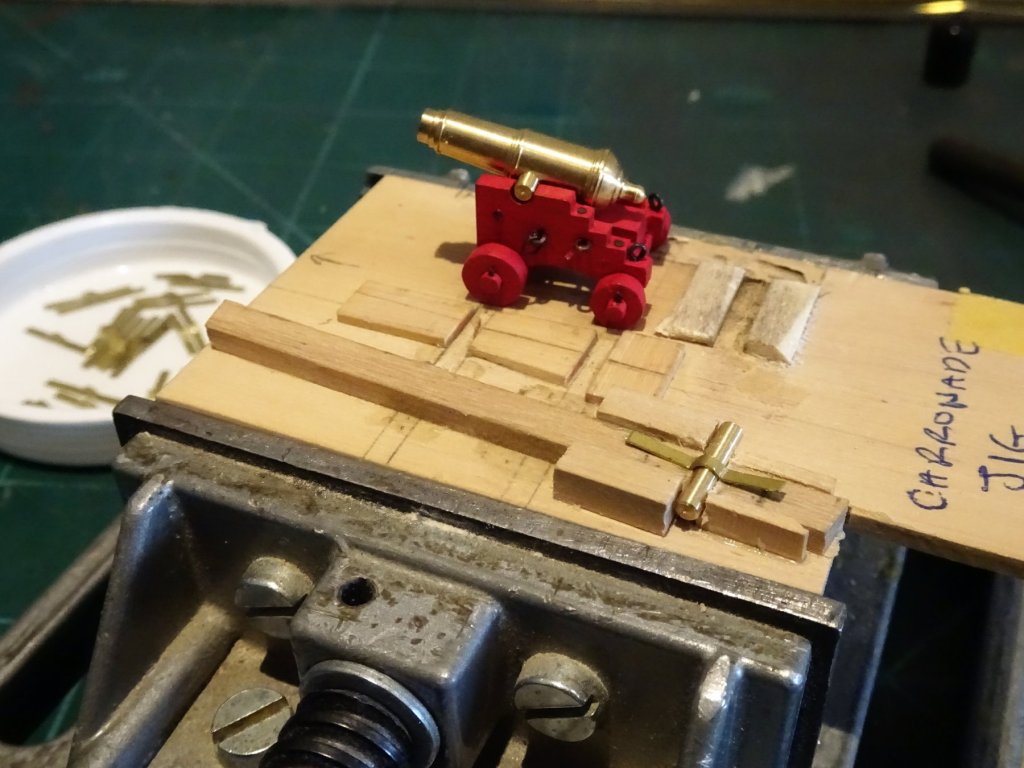
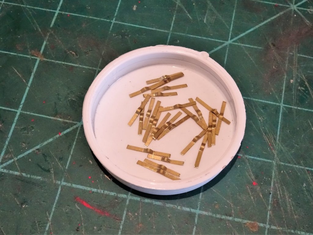
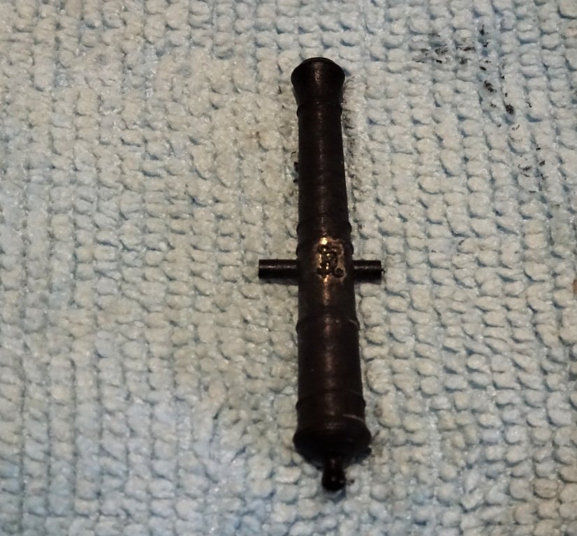
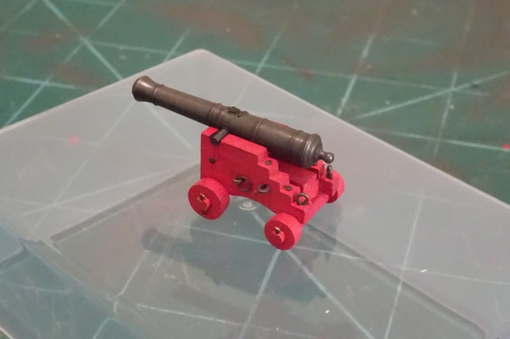
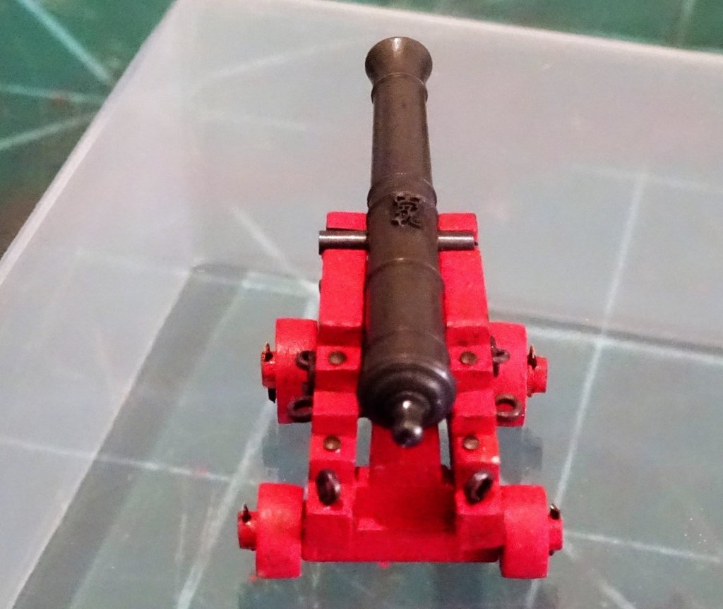
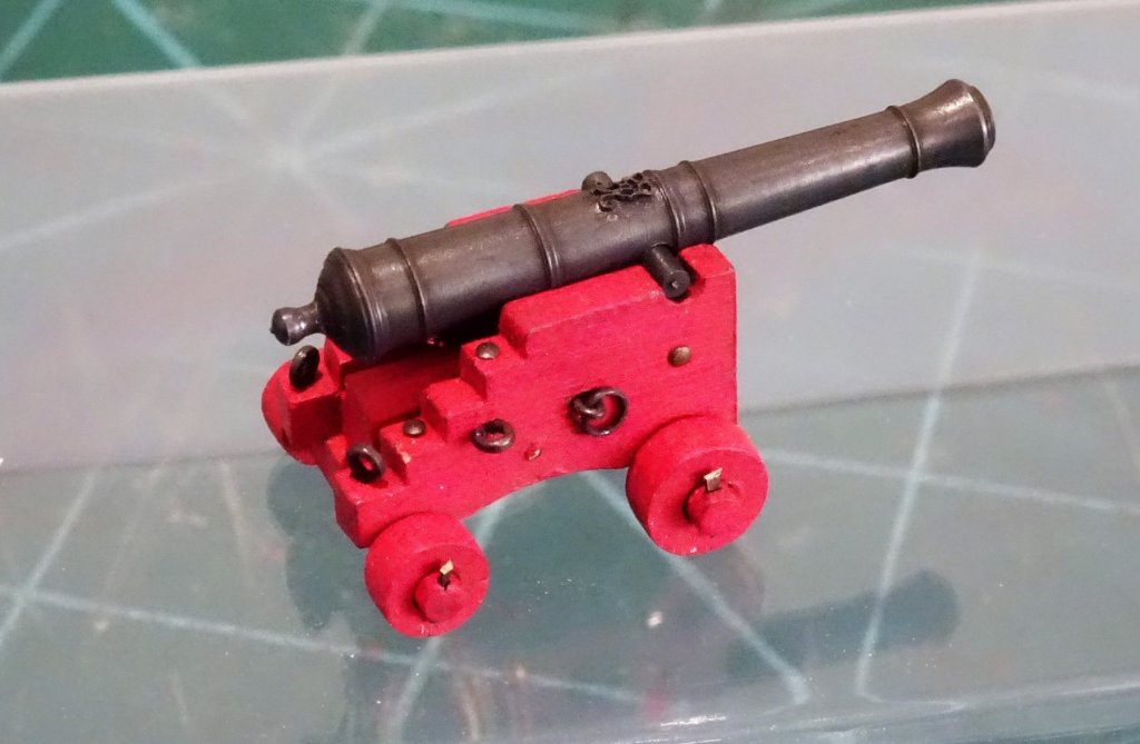
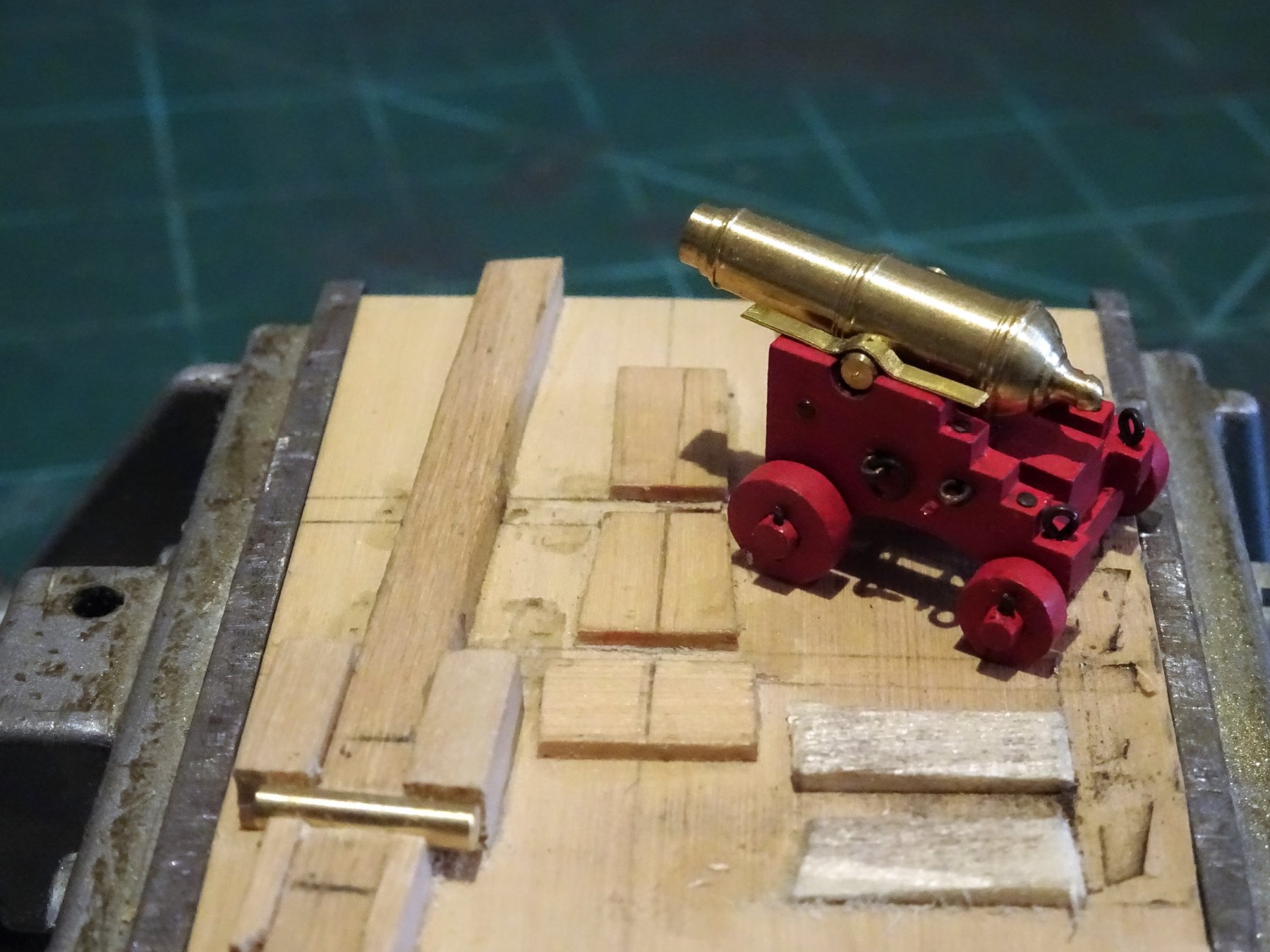
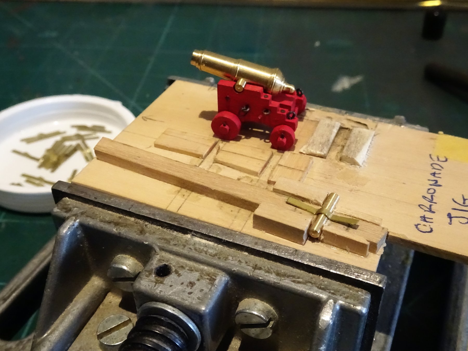
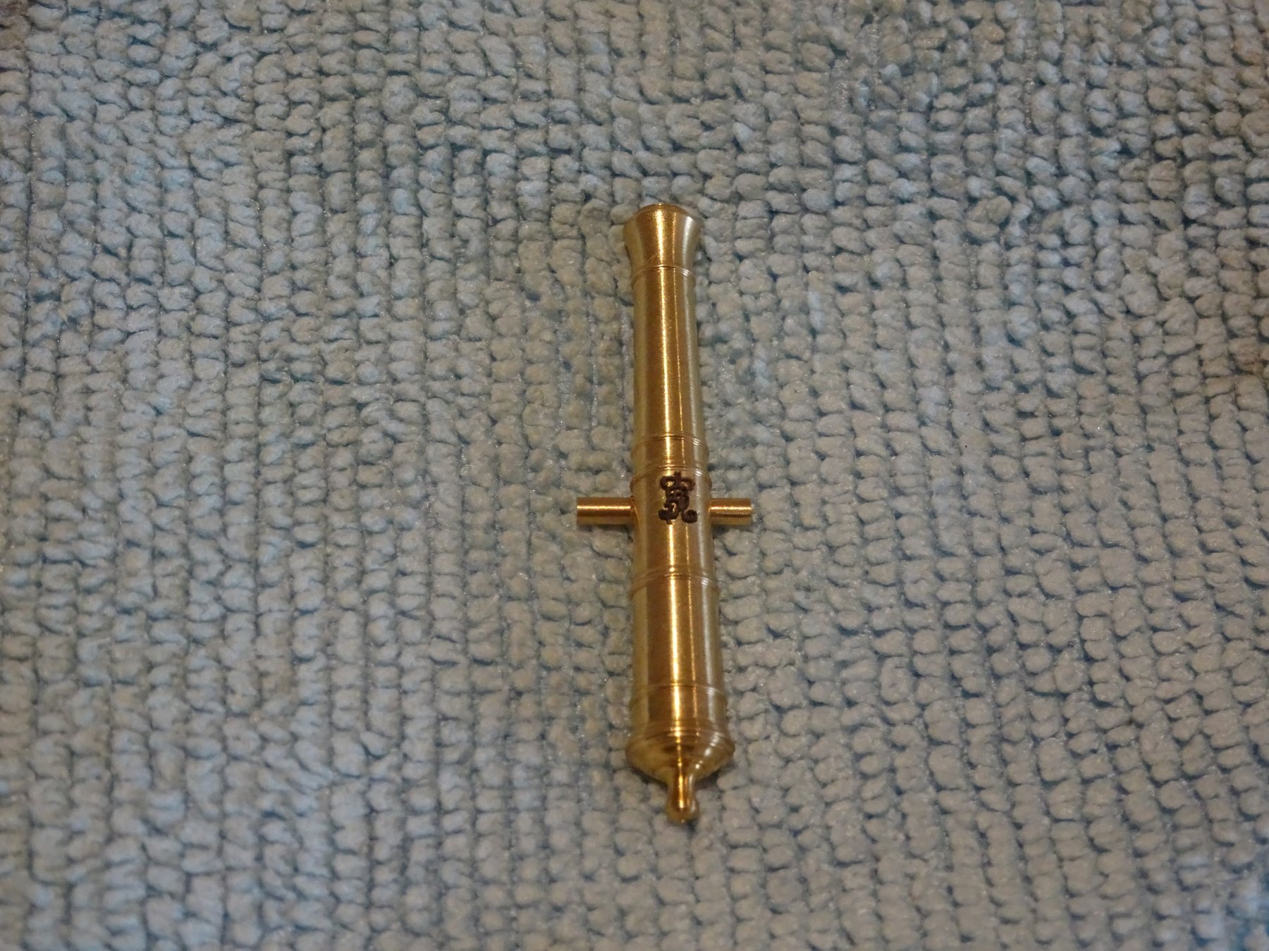
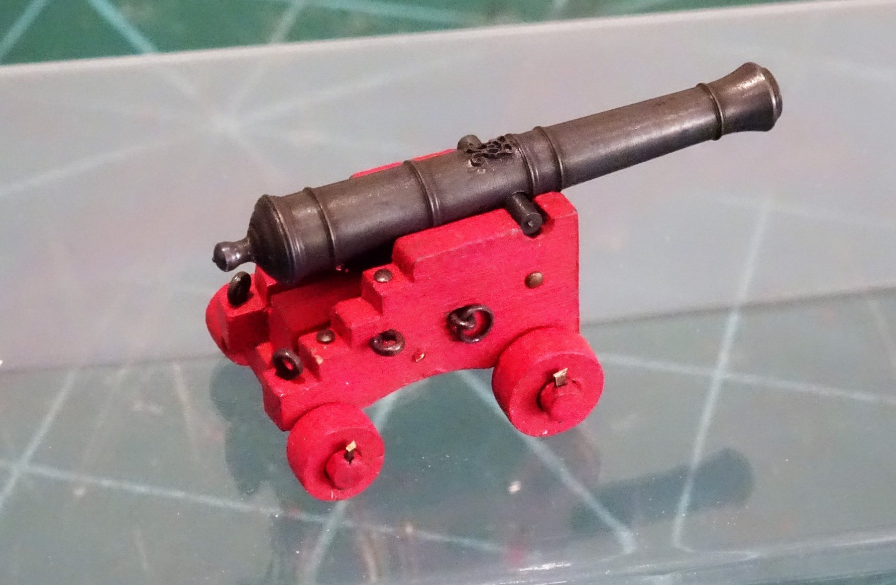
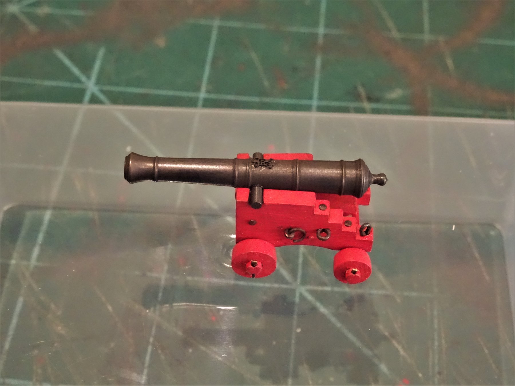
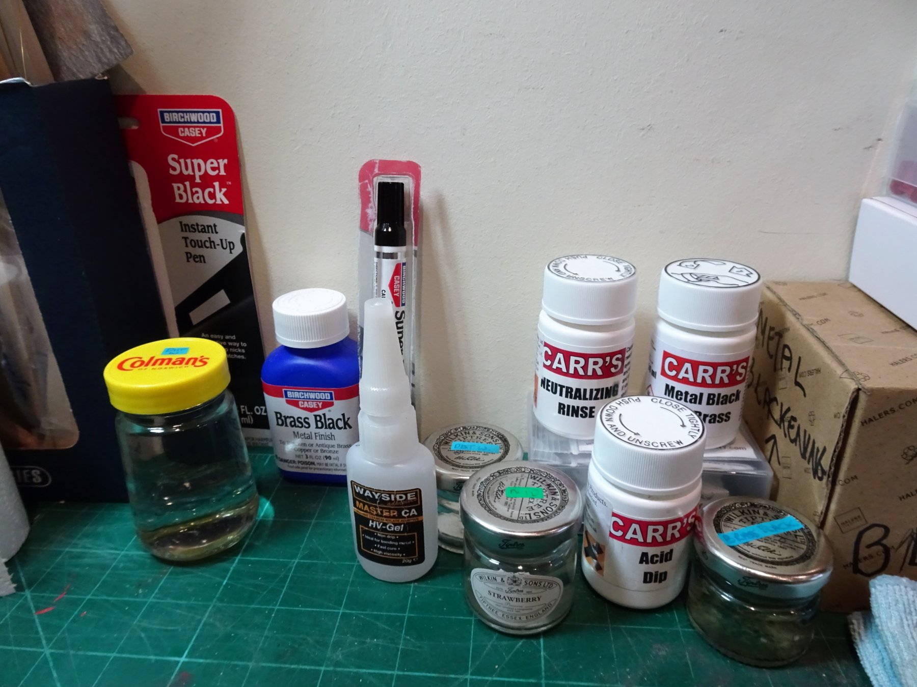
 Post 71 Gun Blackening. I prefer to chemically blacken my guns rather that paint them but my first job is not to start blackening but to make the cap squares to hold the trunnions in place. 6174 A simple jig is made to hold a trunnion at the right depth and some brass strip is formed over this. 6176 It is important to use a pliable not too thick brass strip for this, otherwise the bending process can prove quite difficult. I am using some 0.25mm x 1.5mm brass fret strip left over from my Pegasus build. 6173 With the set made I can leave the finishing off until later. 6207 All the necessary stuff is assembled. I am using a 29/64" long gun to work out the procedure I will use. I am particularly interested in how the GR monogram will respond to the various procedures which will determine whether they are applied pre or post treatment. 6185 A medium sized monogram is blackened and fixed to the barrel using a spot of CA. This has been pre-blackened using some USA stuff called Birchwood Casey Super Black touch up pen which works very well but seems to be rather nasty stuff to the extent that its sale is banned in California. Still I will have very short exposure to this stuff. The barrel is scrubbed in soapy water, rinsed in distilled water, dipped in acid, rinsed again, immersed in the brass black, and rinsed again. 6197 You can see the unblackened area around the monogram which is due to ca contamination. The good news is that the monogram has not been affected by any of the processes. A scalpel blade point is used to scrape away the ca overspill and the process repeated. I found it easier to put tiny spots of ca onto the barrel directly and then place the very tiny cypher and apply a little pressure. 6199 6200 So this is the effect after two 3 minute immersions in diluted Carrs Metal Black to Brass. 6198 6202 Quite happy with the way things have gone and I will now carry on to complete the full complement of ordnance. As an aside if you compare the finish Chuck obtained using paint and weathering powders, what a great job he made of 'iron' ising his guns. B.E. 19/02/2019


- 574 replies
-
- 22
-

-
- cheerful
- Syren Ship Model Company
- (and 1 more)
-
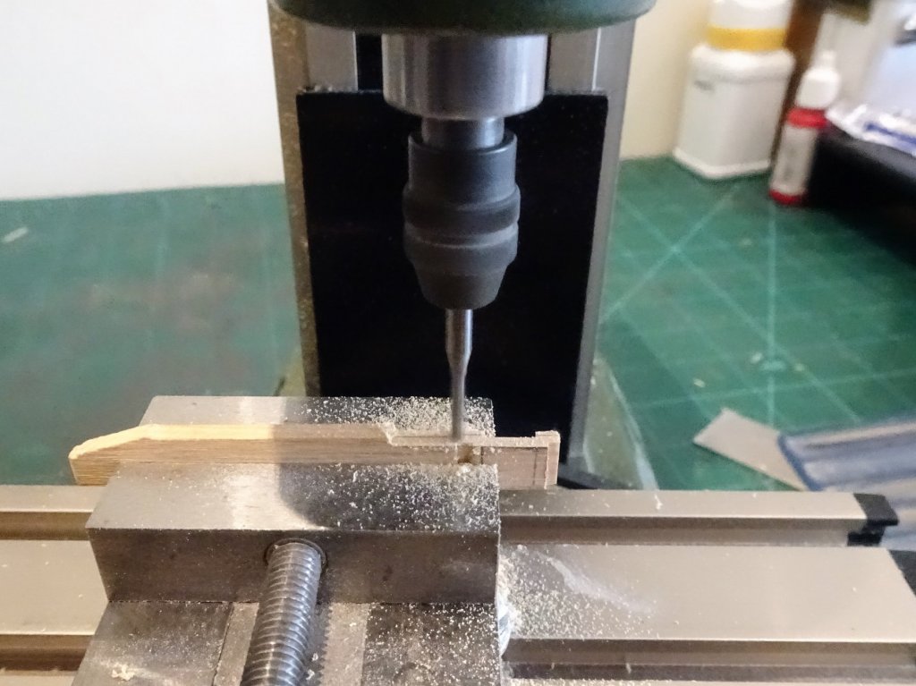
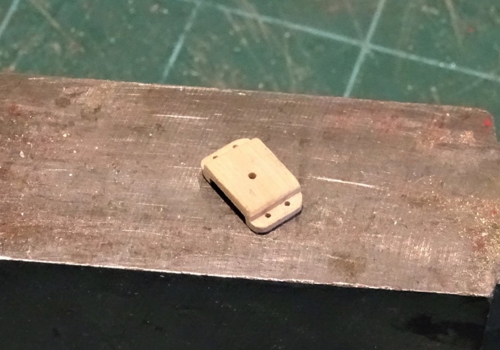
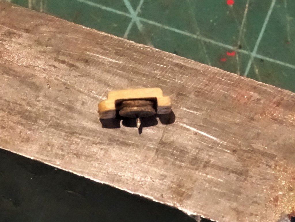
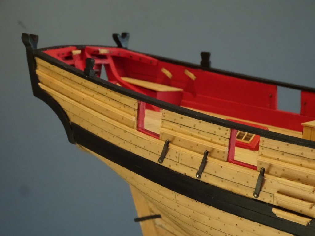
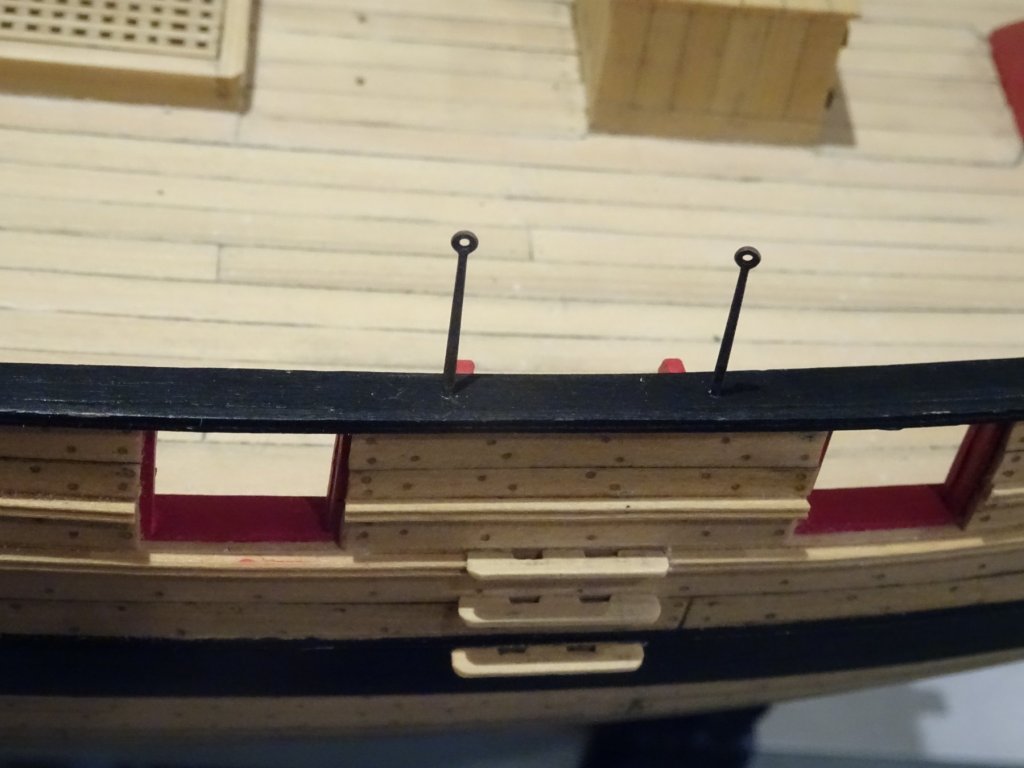
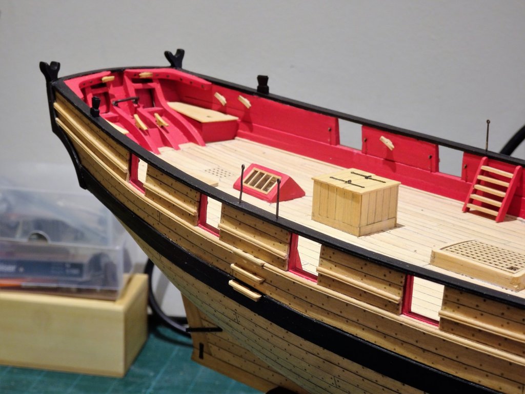
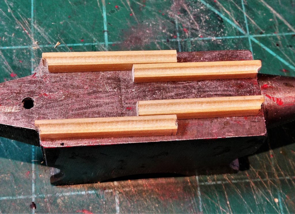
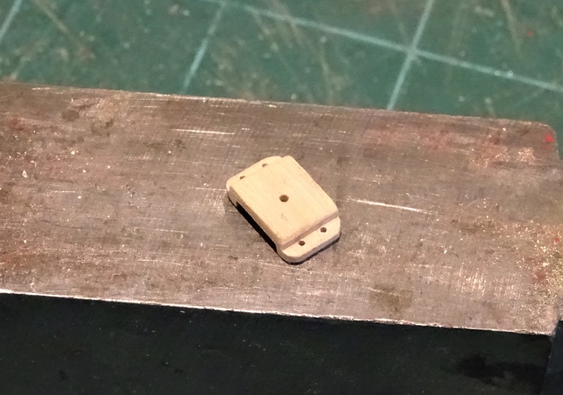
Cheers Guys, and for all the 'like' hits, much appreciated. Post 70 Fixed Block This is a convenient point to make the fixed block for the stem to take the jib outhaul. Taking measurement off the plan the block is made from a scrap of 3mm thick boxwood sheet. 6136 I cut the profile on the little mill, and finished it with files and sanding sticks. 6138 6139(2) 6140(2) 6145 The sheave was made from a slice off some Ramin dowel. 6149 6147 The bench will now be cleared so I can get down to a spot of gun blackening. B.E. 17/02/2019
.thumb.JPG.a3634bcfc48cae7ac672ddb01a6b6d53.JPG)
.thumb.JPG.52808590b74511ffd67f9e7386bb5ab1.JPG)

.thumb.JPG.194f6a373ef5f012bc108f737ec98b19.JPG)
- 574 replies
-
- 22
-
-
- cheerful
- Syren Ship Model Company
- (and 1 more)
-
I have just ordered the Longboat kit, and as with Cheerful I will have your log and excellent work to follow as an example. Thanks Rusty. B.E.
- 152 replies
-
- 1
-
-
- medway longboat
- Syren Ship Model Company
- (and 1 more)
-
Hi Chris, I've always been an admirer of your designed models but have accepted the timber limitations of mass produced kits which I have replaced mostly with Box. For double skinned kits Limewood is fine for the first planking, but as with my Pegasus build I replaced the second planking with a thin Boxwood strip obtained from: http://www.originalmarquetry.co.uk/product_details_335.htm This is fine for 1:64 scale models and the beauty is that it comes in varying widths to allow for shaping of hull and deck planks, and also very easy to work. This is what I would do on your proposed Alert if it becomes available, in the absence of better stuff. The inclusion of 'usual' kit wood, would not put me off buying the kit if I liked the look of it, but as a small enterprise I think you need to follow Chuck's lead and lean towards a more high end market. I consider myself an experienced kit basher rather than a scratch builder, altho' there is not much bashing required in my current Cheerful project. This is what attracted me to Chuck's Cheerful Kit. Well drawn plans. Well written online guide to building the model. Clear history of the subject model Provision of the main areas of the model in quality wood - keel, stem etc. Availability of kit specific timbers - Crown, Syren. Quality fittings and mini kits for those tricky to make items. All this makes for a pleasurable build experience and high satisfaction, eager for the next model. Regards, B.E.
- 906 replies
-
- 13
-
-
Thanks Dowmer, those hooks are quite small and once blackened and fitted there’s not a lot to see. Being basically a lazy builder I will purchase parts if I think they are up to scratch 😉 rather than make them, that’s why my Cheerful build is in the kit section rather than the scratch section. ps.: I have now modified the coamings following your timely advice a few posts back 😊 Regards, B. E.
- 574 replies
-
- 1
-
-
- cheerful
- Syren Ship Model Company
- (and 1 more)
-
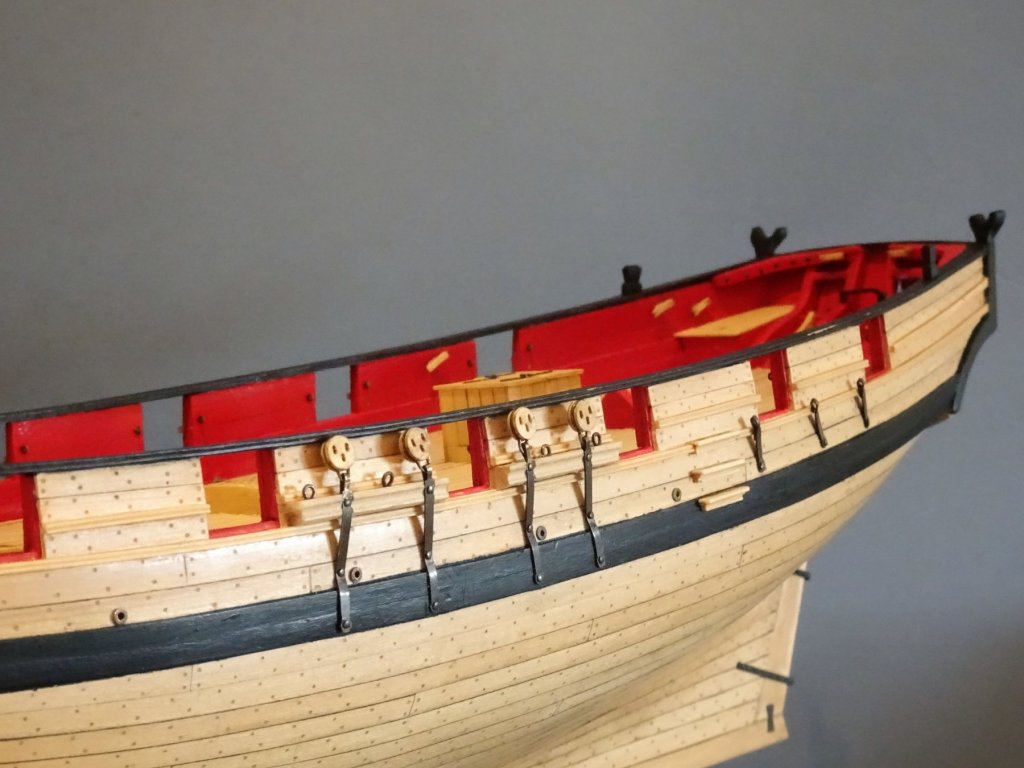
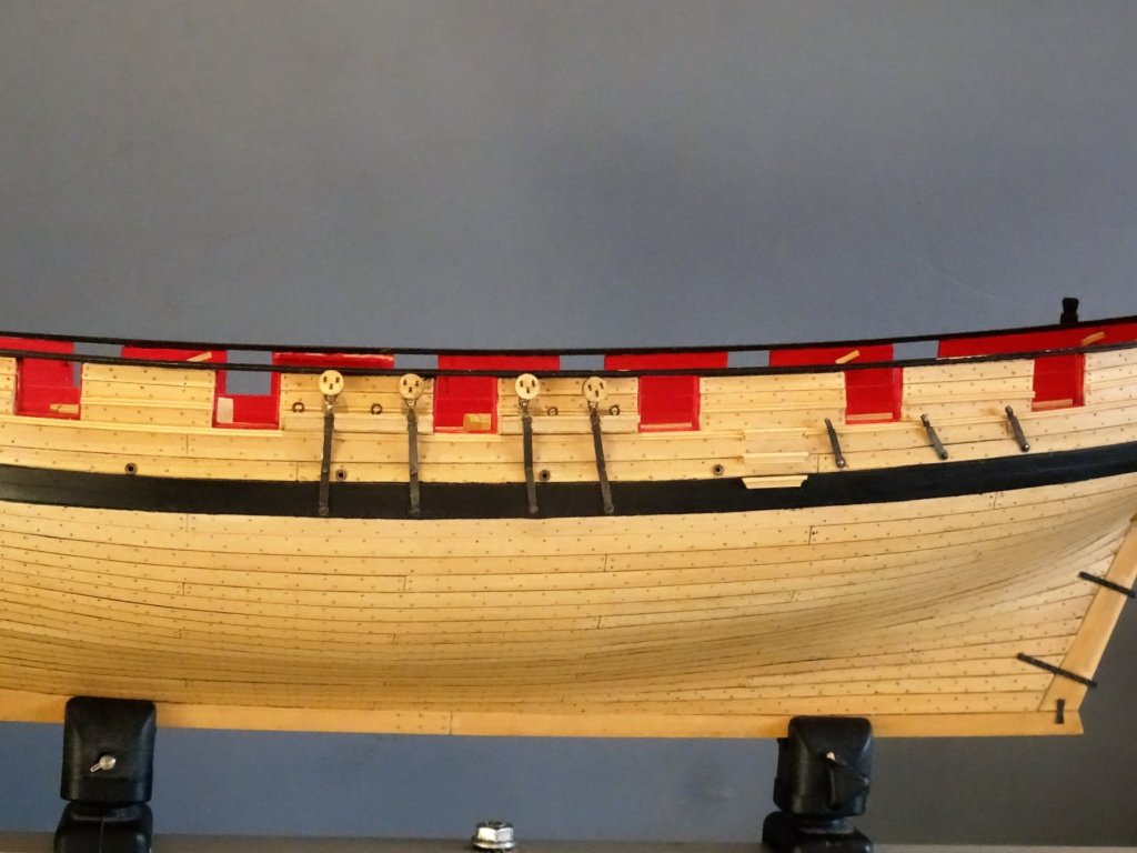
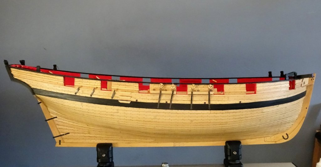
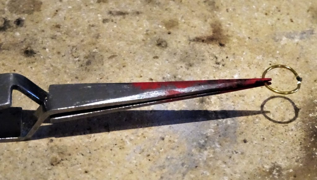
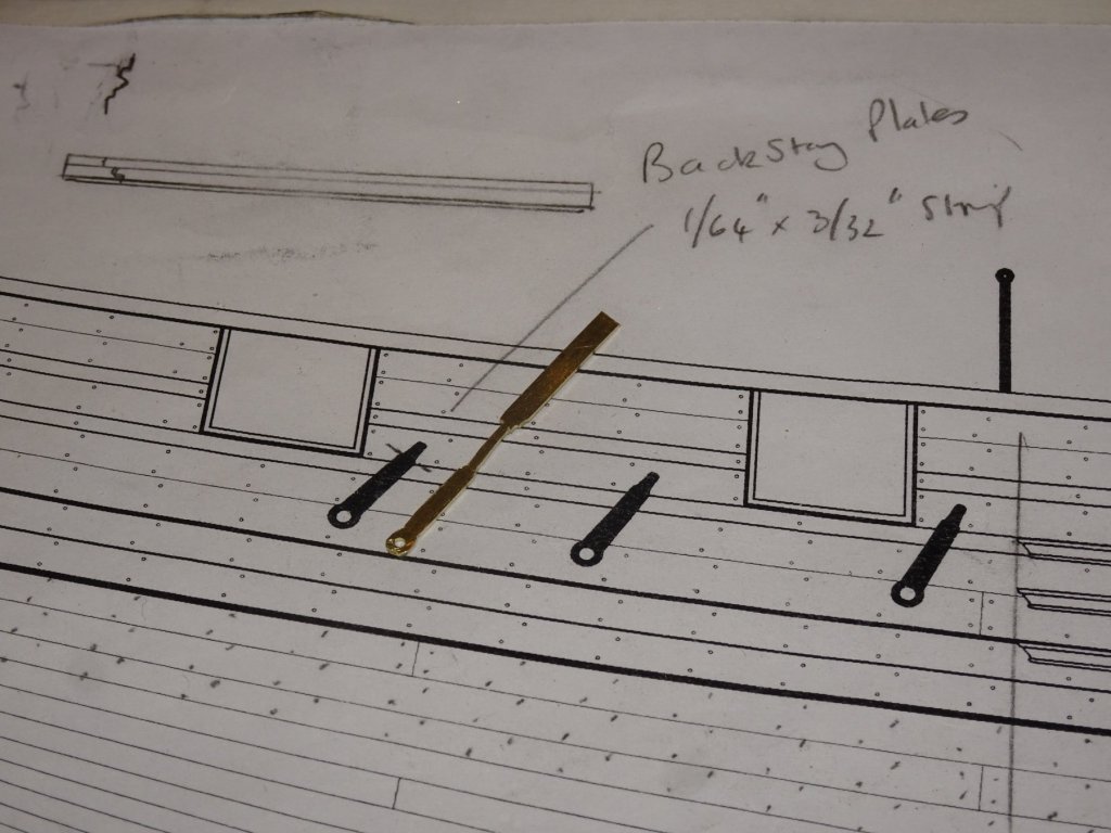
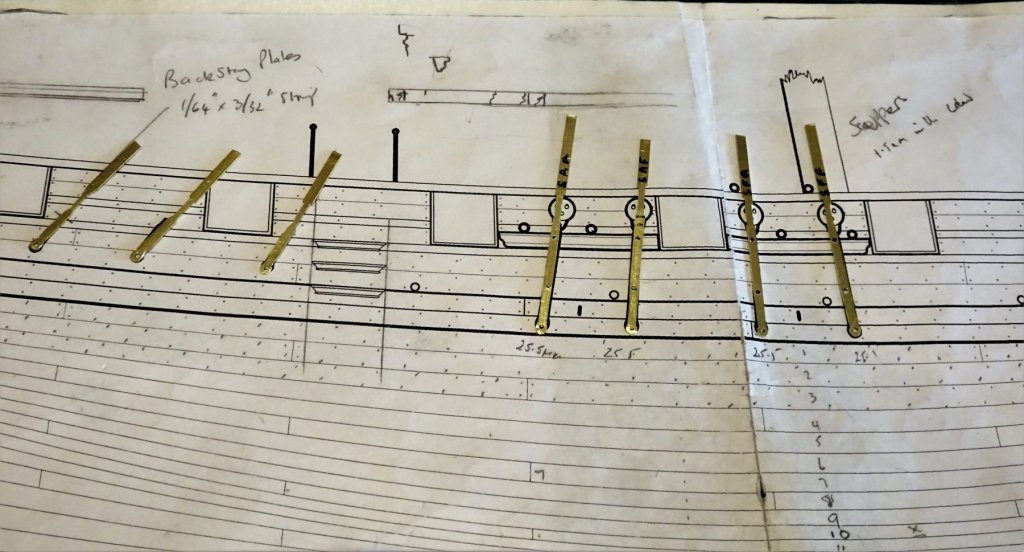
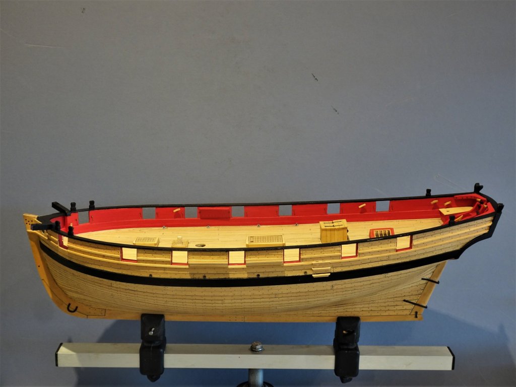
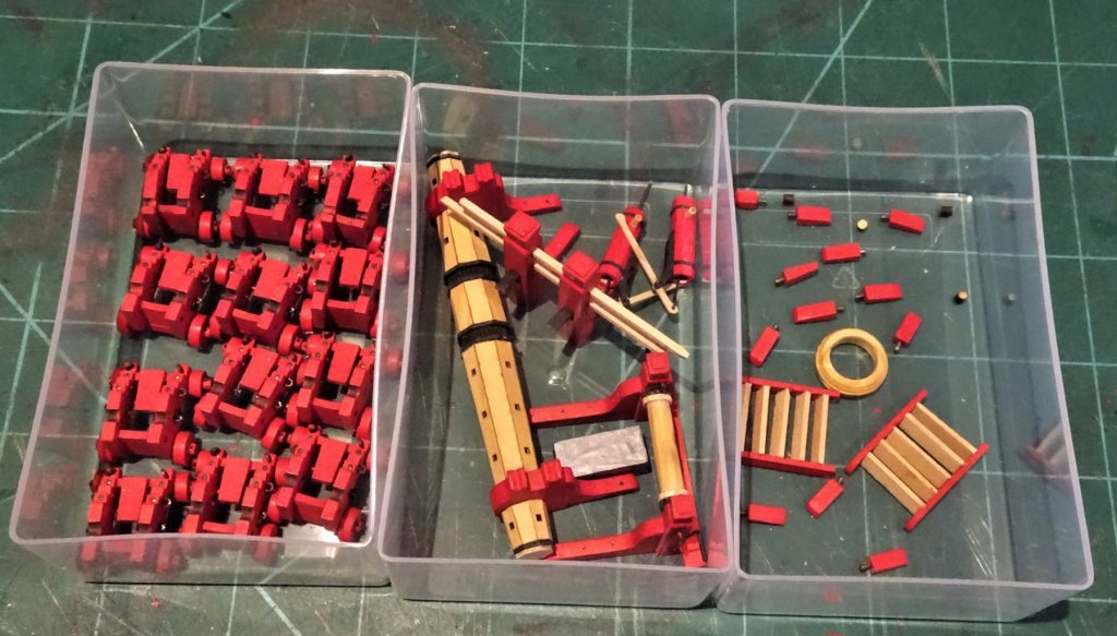
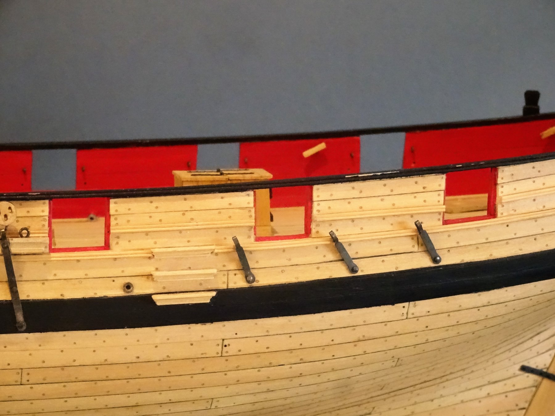
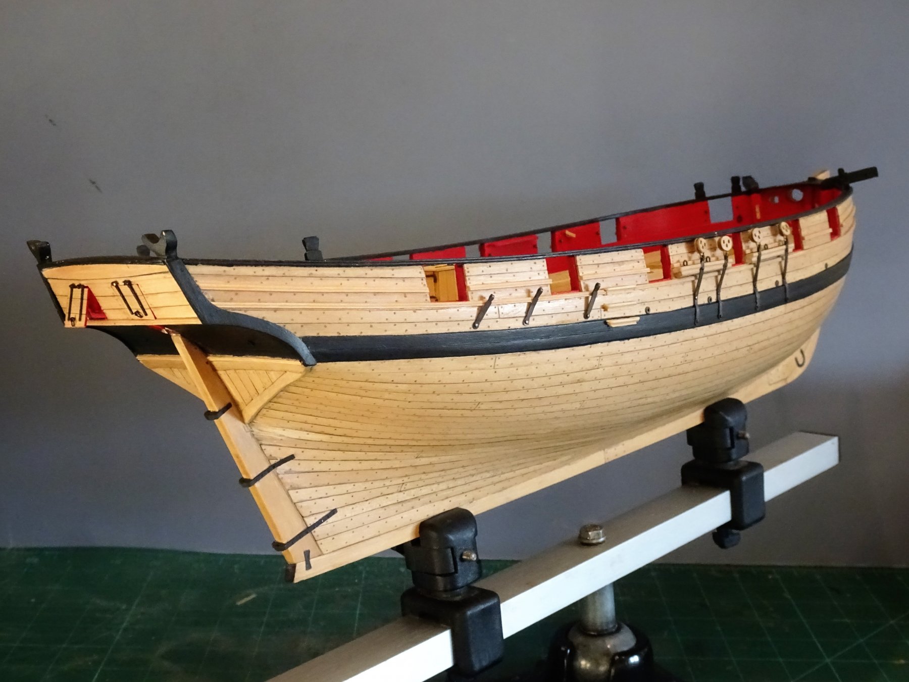
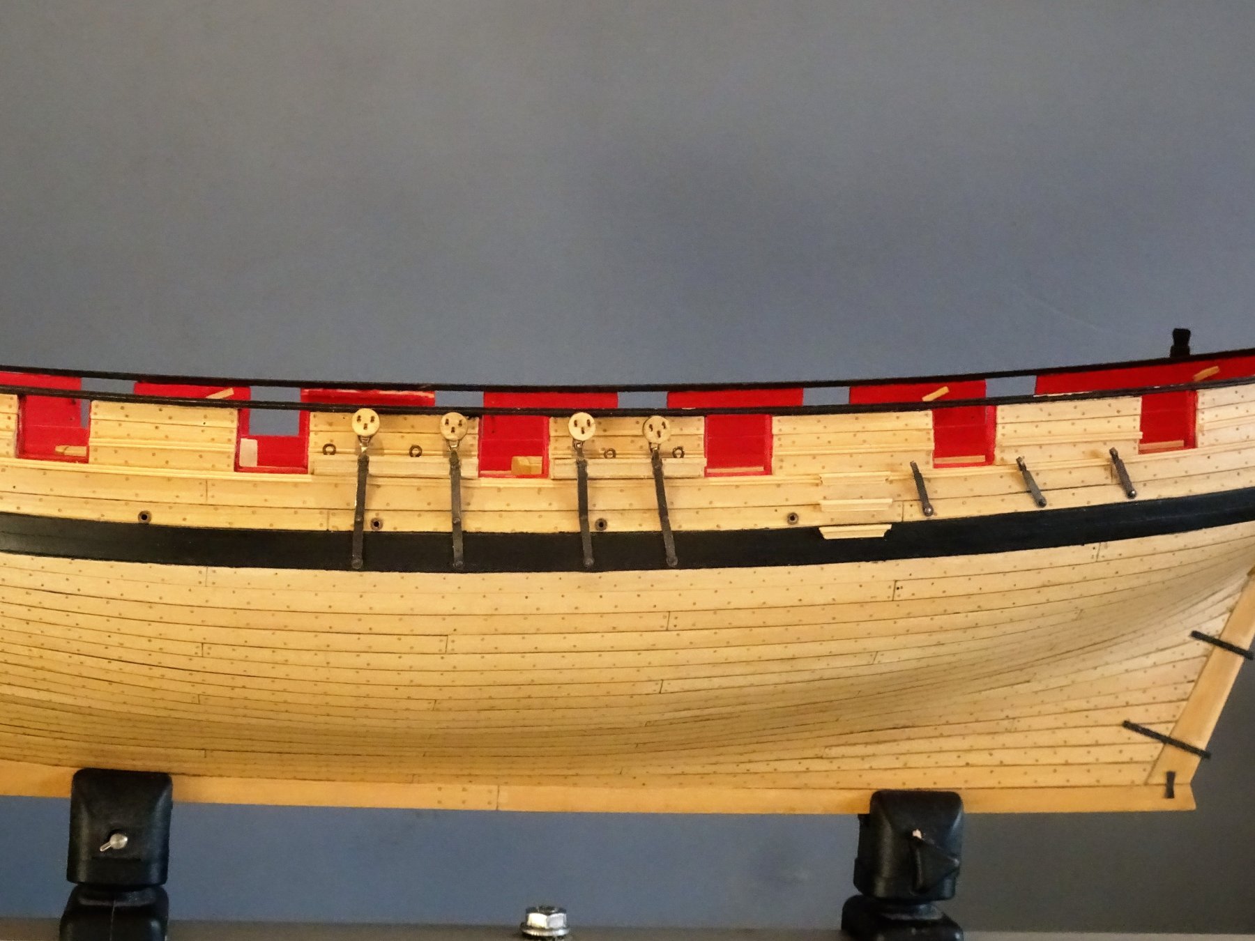
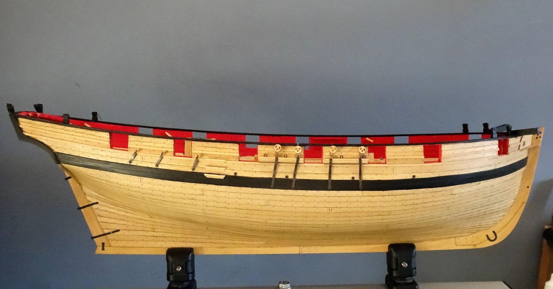
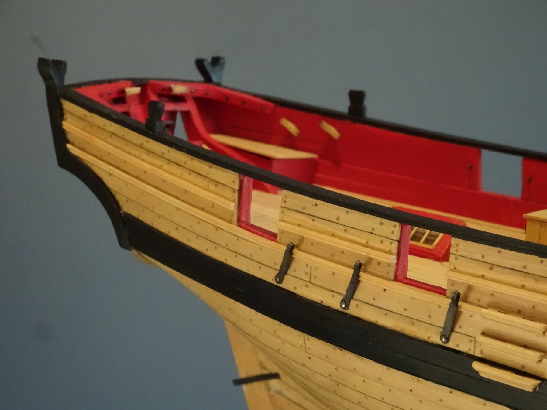
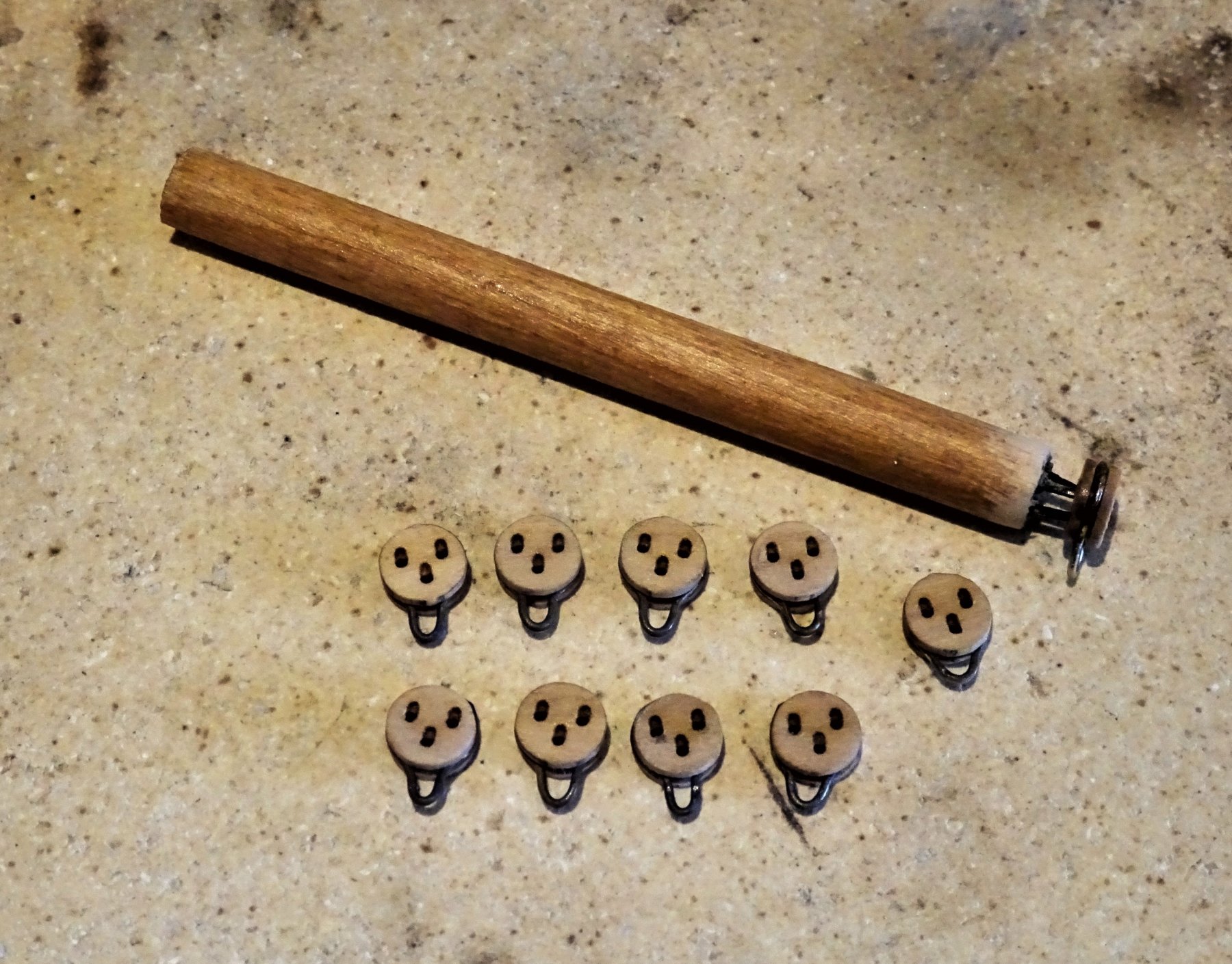
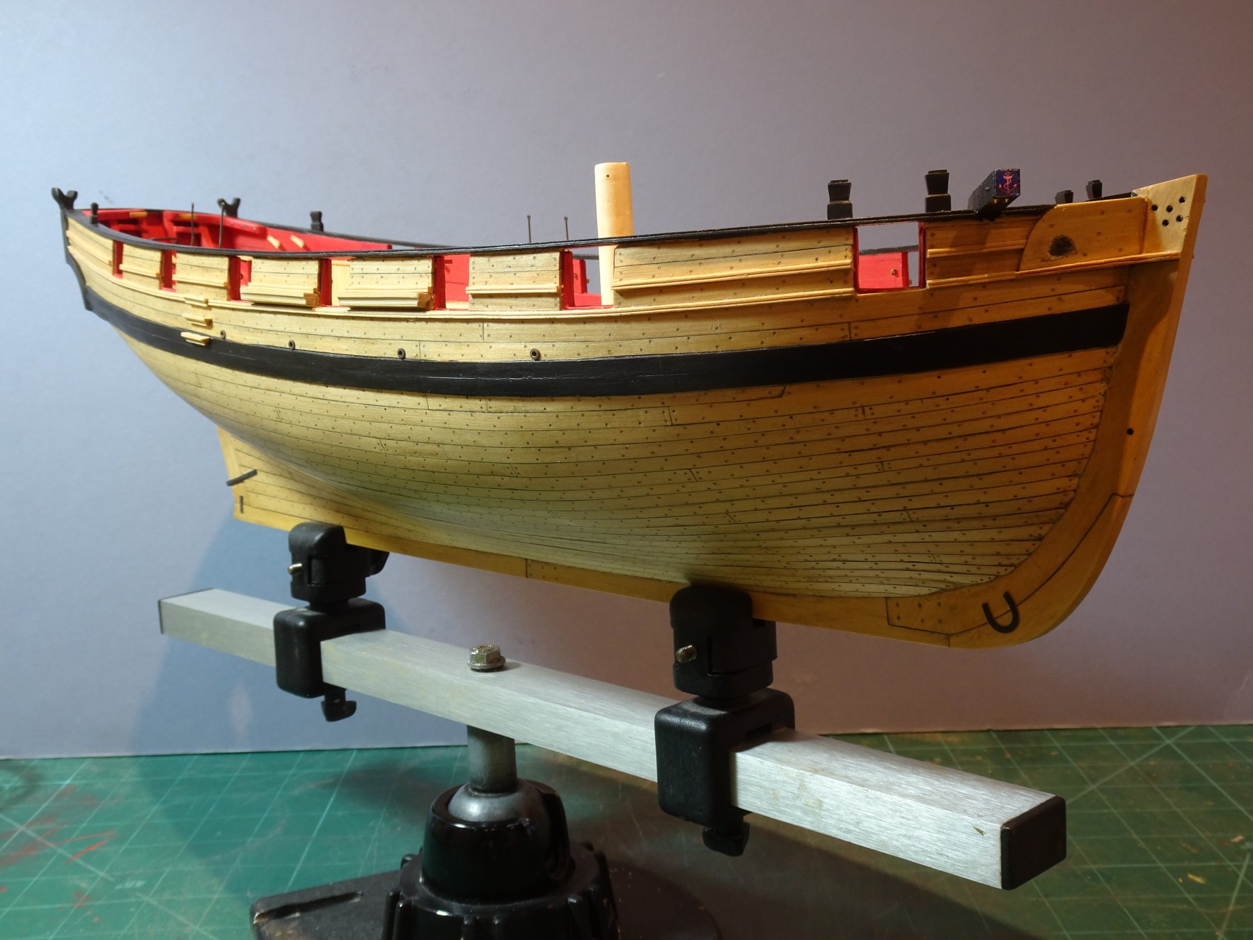
Post 69 Completing the Chainplates I now get back to fettlin' the Chainplates and with the deadeye strops completed I can now gauge the width of the chainplate fold over to secure them. A further 'on model' trial fit of the Chainplates to check positions and form the bends required where the Chain fits over the wale. 6078 This is a bit of a scary exercise and is done with the model supported on towels and a flat metal edge used to press the chains into shape. This needs to be done before blackening for obvious reasons. 6080 The chains are then blackened; washed in soapy water, rinsed, dipped in acid, rinsed again, submerged in the brass black. and once again rinsed. I also tested a deadeye in the blackening fluid to test the effect on the Boxwood. There was no visible effect on either the colour or the stability. This is just as well as once the chainplate has been messed about fitting and adjusting the connecting loop, a further dip in the brass black is required. This is one of the downsides to metal blacking items such as this rather than painting them, but for me the finish is far preferable. All this is a fiddly exercise, particularly getting the deadeyes to sit reasonably level with each other. Tiny differences in the strop and chainplate loops contrive to work against you, to produce an uneven top line. 6129(2) In relation to the fixing of the chainplates I have followed the Admiralty plan and placed the second bolt above the wale, also shown on Chuck's plan, rather than have the two fixings thro' the wale. It took a days work to complete one side of the Chainplates, with still a little more adjusting and touching in to do. Backstay plates I am using Caldercraft 5mm brass etched hooks for the rigging attachment to the Backstay plates so the plate loops need to be made to accept these. 6133 6119 Much quicker to make and fit the backstay plates. Overall three days work to complete and fit the ironwork. 6125 6120 6128 6131 I can now leave the Blacksmiths Forge and return to the Carpentry shop. B.E. 15/02/2019
.thumb.JPG.23a496033c0750711bef8ab91ebe62bd.JPG)


.thumb.JPG.10f2d4b981b77ff9d27bea9c256827bb.JPG)
- 574 replies
-
- 29
-
-
- cheerful
- Syren Ship Model Company
- (and 1 more)
-
Hi Martin, de-ionised water (distilled water) is simply used to neutralise the acid before I dip in the blackening solution, and then to stop the process once the depth of colour is achieved. Cheers, B.E.
- 574 replies
-
- 1
-
-
- cheerful
- Syren Ship Model Company
- (and 1 more)
-
Much appreciated Rusty, your Cheerful log has been a constant reference source and inspiration during my build. I wish I had achieved the same cleanness of Hull planking so evident in your fine build. Regards, B.E.
- 574 replies
-
- 2
-
-
- cheerful
- Syren Ship Model Company
- (and 1 more)
-
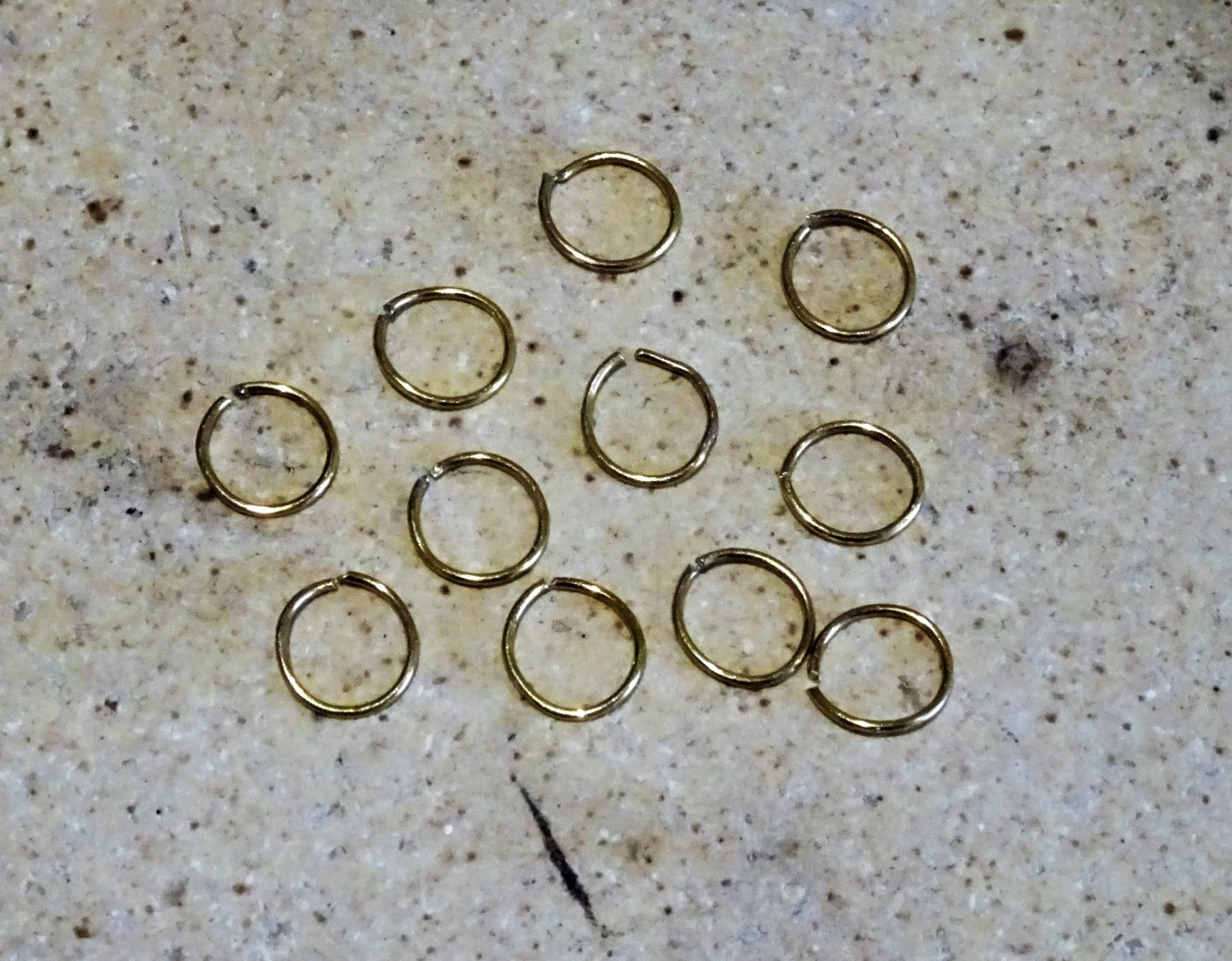
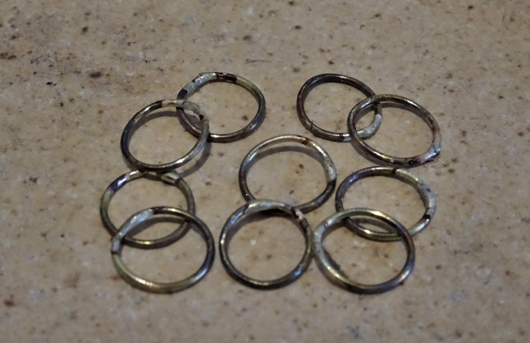
Post 68 Making up the Deadeyes Associated with the Chainplates are the deadeyes and strops. Chuck indicates 6mm deadeyes and 22 gauge wire for the strops. (this is 0.64mm ø (awg) or 0.71mm ø (swg) I used Chuck's self assembly Boxwood deadeye kit, and 0.6mm ø wire. 6051 I sacrificed one deadeye to form a jig to hold the others for char removal, stropping, and cleaning up. Deadeye strops Tricky little beggars these, a ring of wire needs to be formed sufficiently large to just fit over the deadeye, but small enough not to form too large a loop at the bottom to connect with the Chainplate. The process starts with a little bit of best guess to gauge the correct size. 6052 Once I've got the fit, I can proceed to make the number required, each one tested for size on the deadeye jig. 6050 Once formed the ring is cleaned in acid, dipped in de-ionised water before soldering, and quenching once again in the de-ionised water. A small amount of solder paste is applied to the join, a quick blast of the torch, a flash of silver and the jobs done. 6053 Hoping they don't break when the bottom is squeezed with long nose pliers to form the loop. In cleaning up two broke but the rest held good.They are then chemically blackened before fitting. 6055 The completed set with a couple of spares. For security silver soldering is the only way to go with this sort of thing. The whole process took around 4½ hours. I am conscious that the deadeyes need to be level with the underside of the Capping Rail when attached to the Chainplates so I considered it beneficial to complete them in advance. Back to the Chainplates. B.E. 11/02/2019


- 574 replies
-
- 17
-
-
- cheerful
- Syren Ship Model Company
- (and 1 more)
-
Looks wonderful Chris, I don't think I will be able to resist that one ☺️ B.E.
-
Just enjoyed reading thro’ your log Rob, love your approach to the build, and you’re doing a great job. Impressive stuff 👍 Cheers, B.E.
-
My eye is drawn to the 0.3mm line Jason, it looks to have nicer definition. I like the look of frapped side tackles, keeps everything neat and a nice sag is easily achieved. B.E.
-
Sorry for your feelings of dissatisfaction Bob, I guess we've all been there at some point with our modelling results, but nevertheless she looks a nice model to me. Wishing you better health in 2019 and a renewed enjoyment in your next project. Regards, B.E.
- 359 replies
-
- 5
-
-
- prince de neufchatel
- model shipways
- (and 1 more)
-
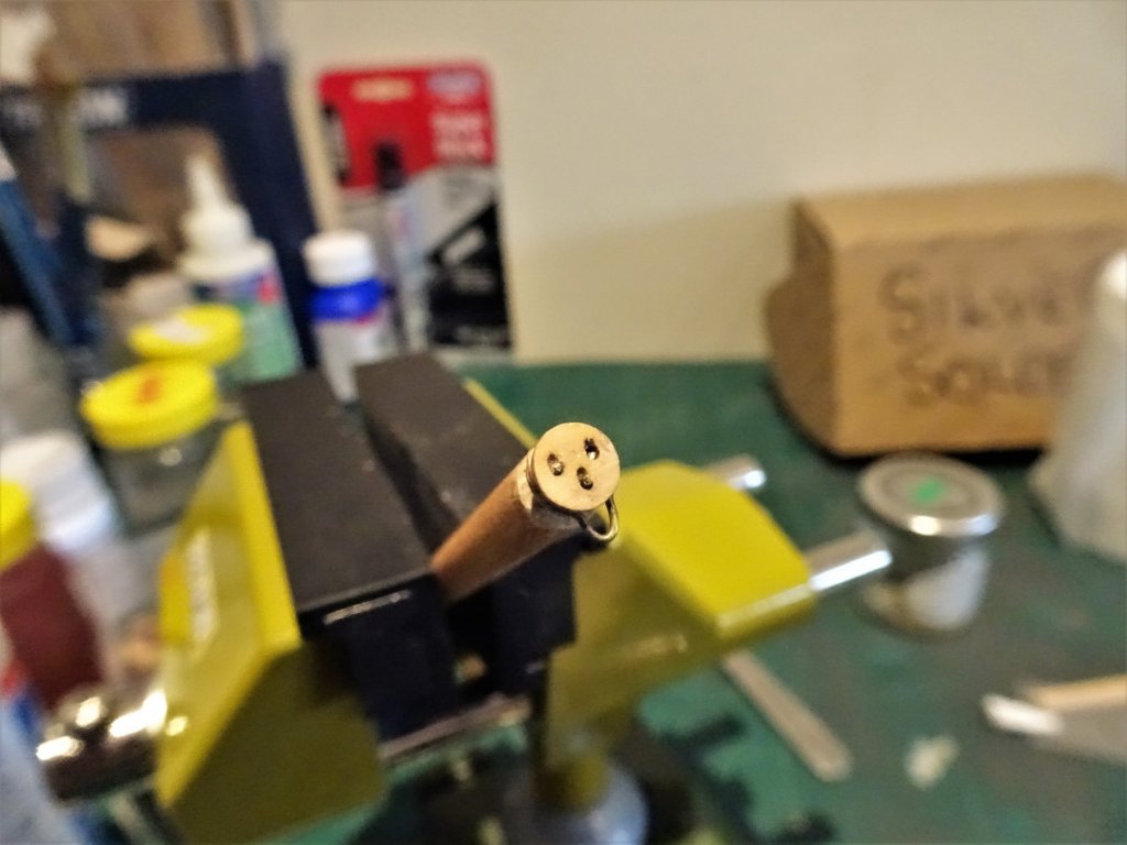
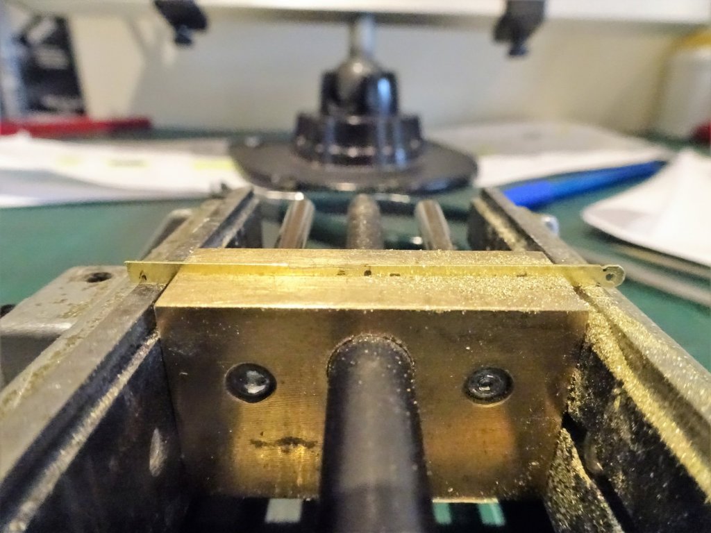
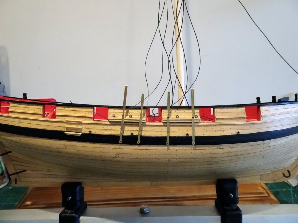
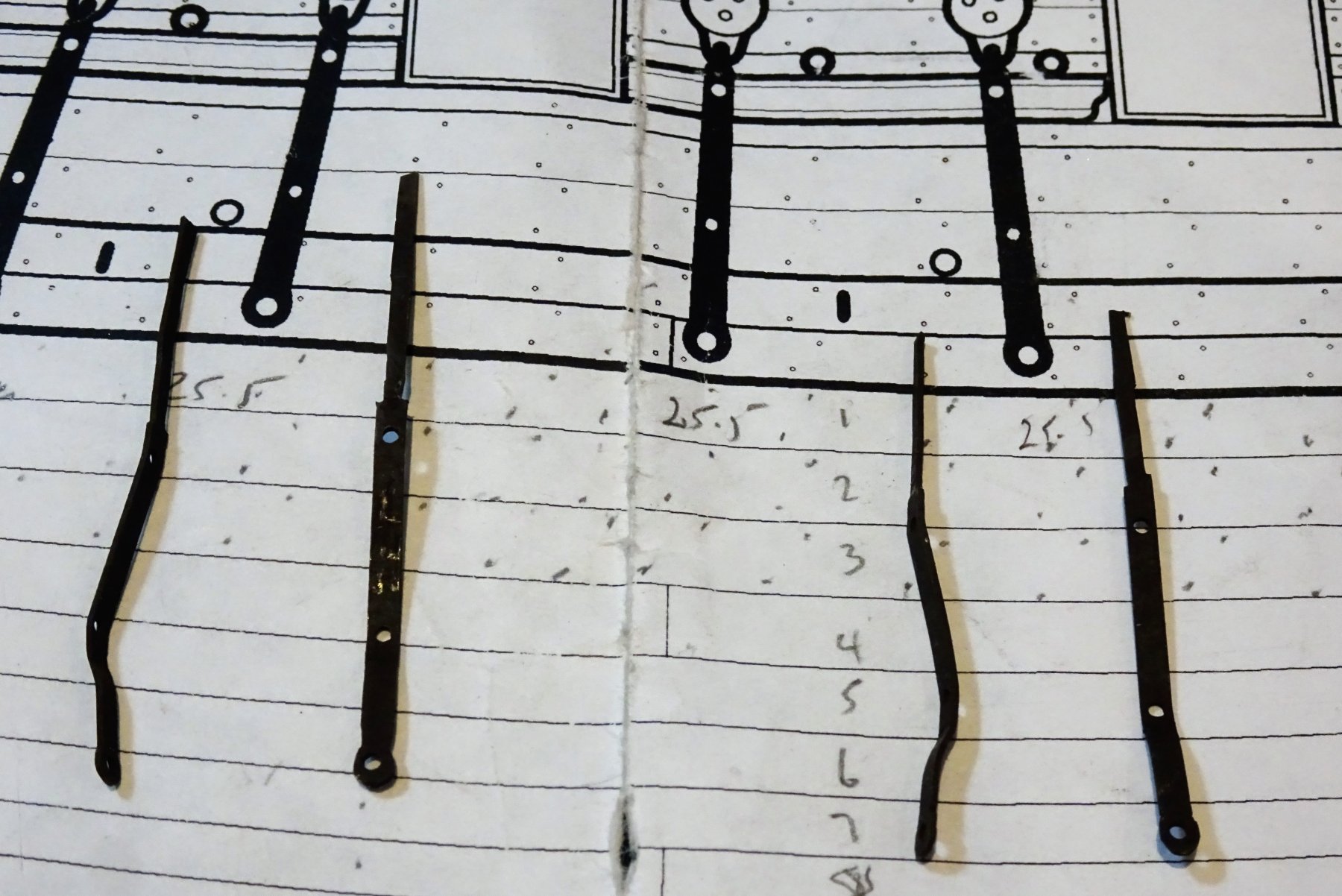
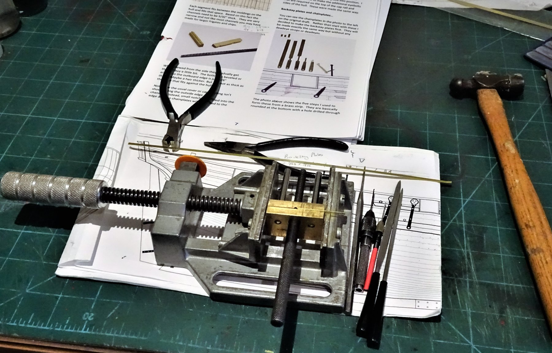
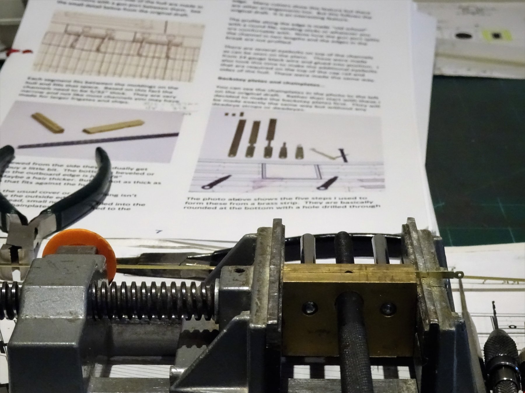
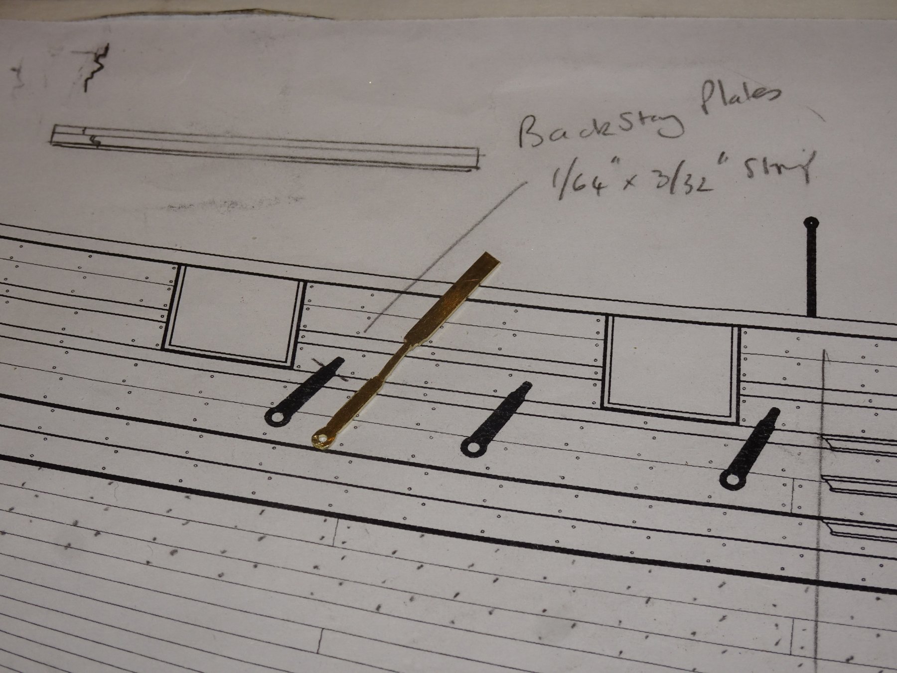
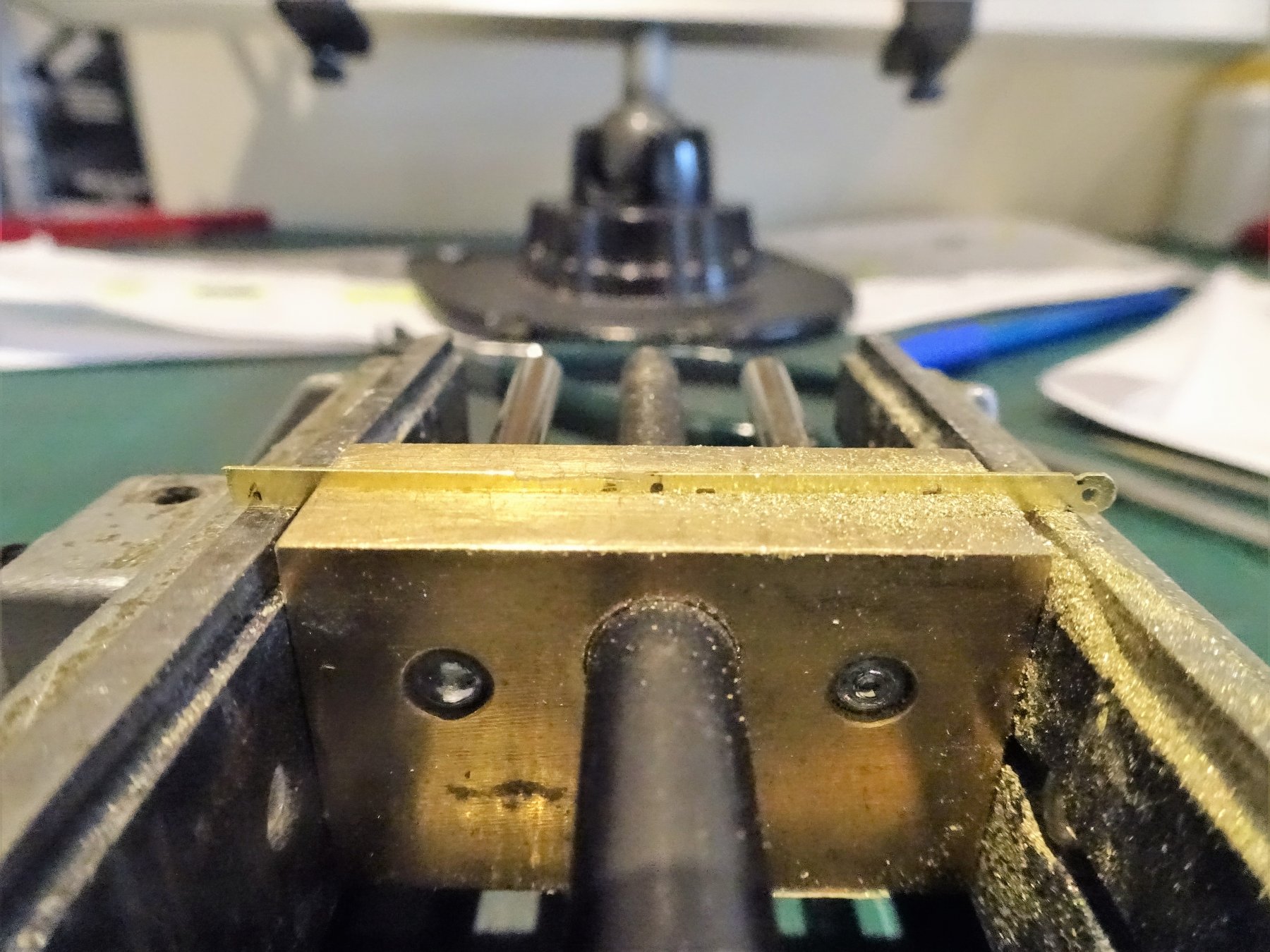
Post 67 Chain and Backstay plates. As indicated by Chuck I obtained some 1/64"x 3/32" brass strip to form the iron work. The K&S strip is quite easy to work, and I don't think I will need machinery to produce these fittings. 5891 I did need to work out a strategy to hold and work these quite small items. 5892 One of the things I wanted to replicate was the distinct round at the base of the plate where the bolt enters, rather than just a straight taper up to where the hook is formed. 5898 A prototype backstay plate. With the prospect of fourteen plates to make, my mind fondly drifts back to the brass etched versions provided with my Pegasus kit. However in practice the task proves less onerous than first may be thought. The Chain plates are measured against the model and cut to basic shape. Each strip is marked with its position on the channel. 5903 Having formed the plate the slight taper is filed in. 5907 I have left the chainplates overlong at this stage; before finishing I need to get the angles correct against the channels, and for this I need to rig a temporary mast and shrouds to be able to mark the channel slots. 5919 So the next stage is to set up a temporary shroud rig. 5914 5913 With the lines established I can now move ahead and mark the slots on the channels and fixing points for the Chainplates. 5970 With the slots cut and positions checked final finishing of the Chainplates can proceed. B.E. 10/02/2019


- 574 replies
-
- 21
-
-
- cheerful
- Syren Ship Model Company
- (and 1 more)
-
Good to hear Hartmut, yes Pete is still going strong, heavily involved with his wild life rescue interest, and caring for his orphan squirrels. Not so active on ship modelling at present, but the Victory forum is still alive altho' not as active as in previous years. Your fine Pegasus and Agamemnon builds are still there along with most of the other builds, recovered from a systems crash a while ago. Michael D is still progressing his wonderful 1756 Victory conversion, and the significant data on all things Victory is largely intact. I do go in and have a look from time to time, but I don't have any current builds posted on there. Regards, Maurice.
- 574 replies
-
- 2
-
-
- cheerful
- Syren Ship Model Company
- (and 1 more)
-
Thank you Thomas, Dowmer and Hartmut. 🙂 @ Dowmner - I believe the Channels were simply bolted to the side, thro' the planking into the frames. On larger vessels they usually had supporting brackets, but channels were fairly lightweight structures whose main purpose was to spread the shrouds, not as sometimes mistakenly thought to also bear the weight of the pull of the shrouds. That was the job of the chainplates. @ Hartmut - long time no hear Hartmut, but a nice surprise all the same. Hope you are well and still enjoying ship modelling. B.E.
- 574 replies
-
- 2
-
-
- cheerful
- Syren Ship Model Company
- (and 1 more)
-
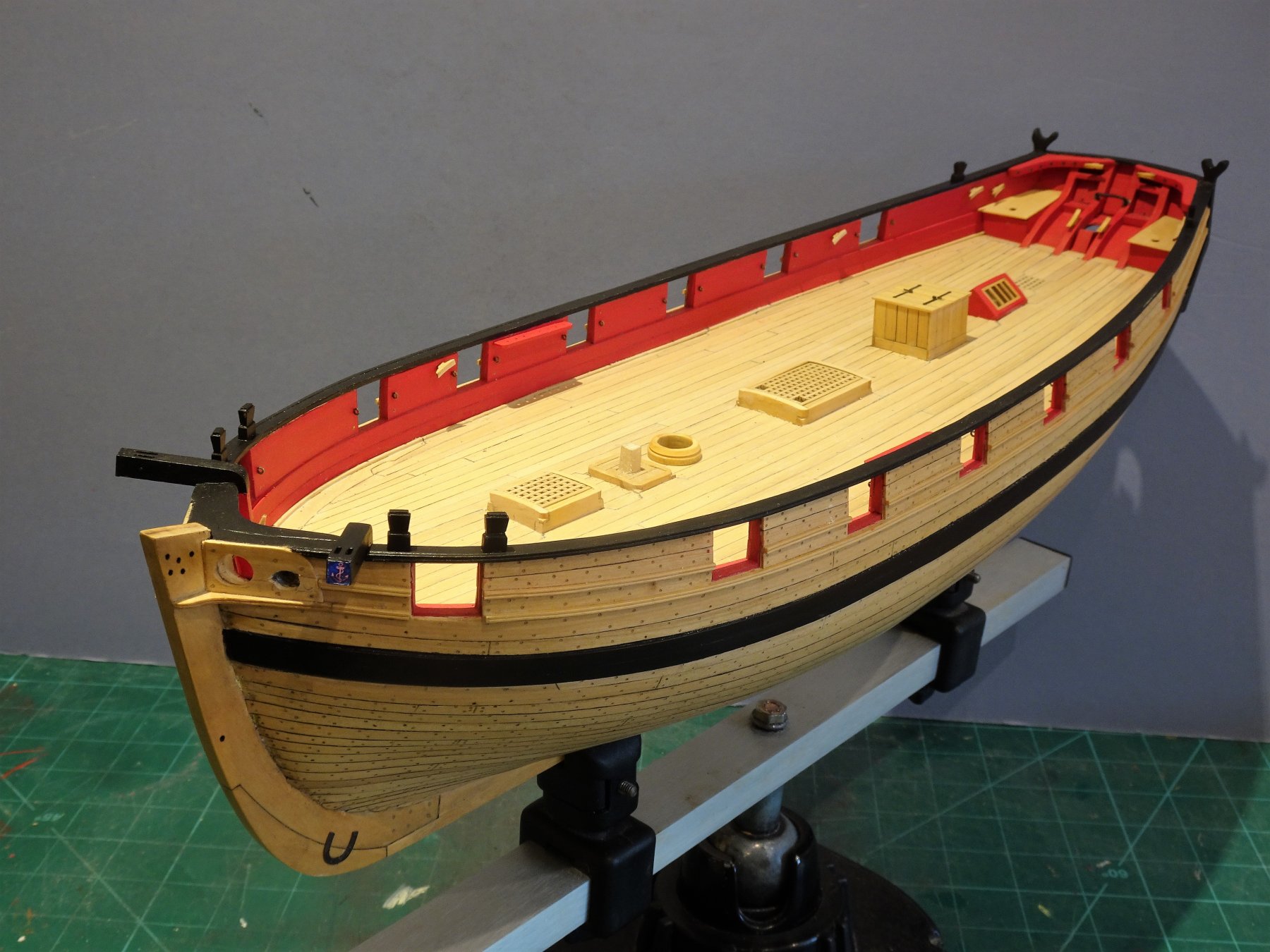
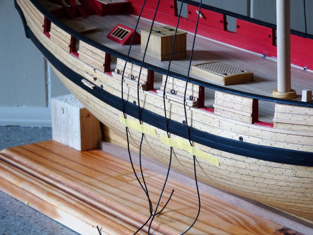
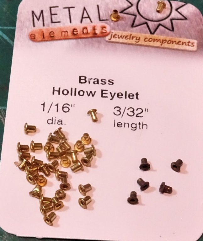
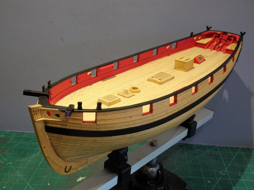
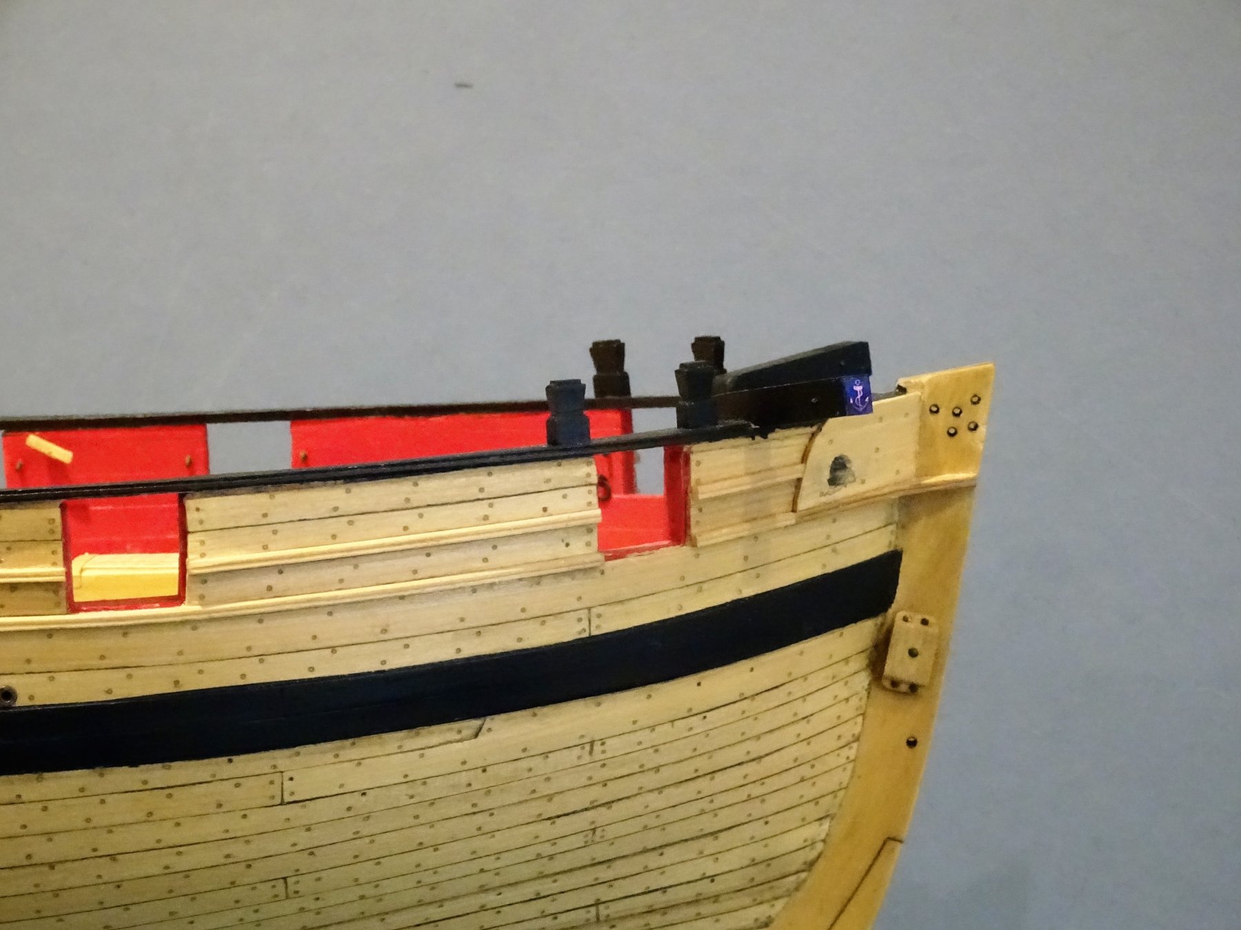
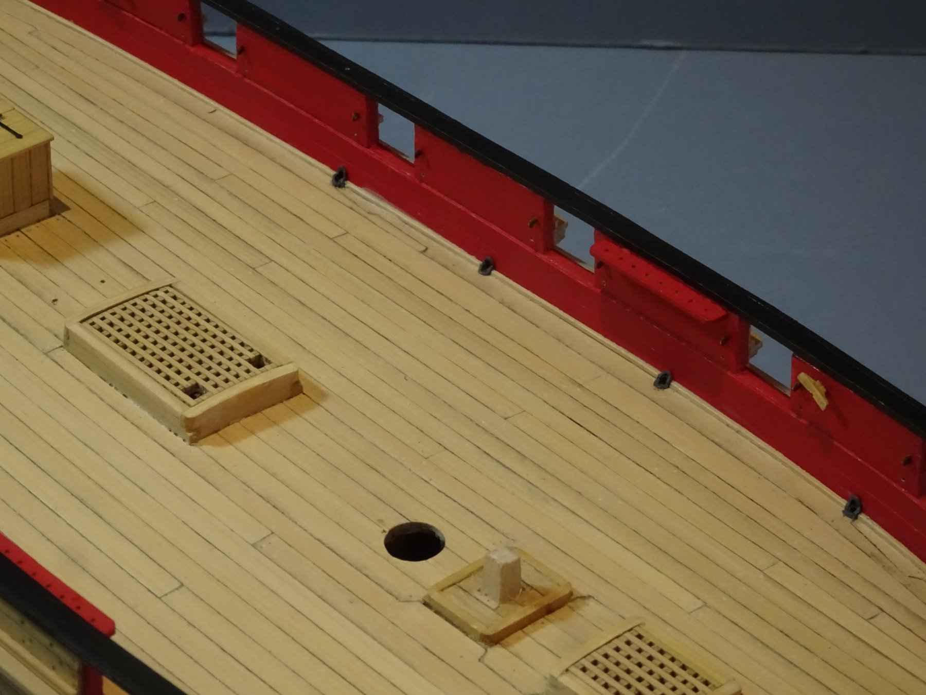
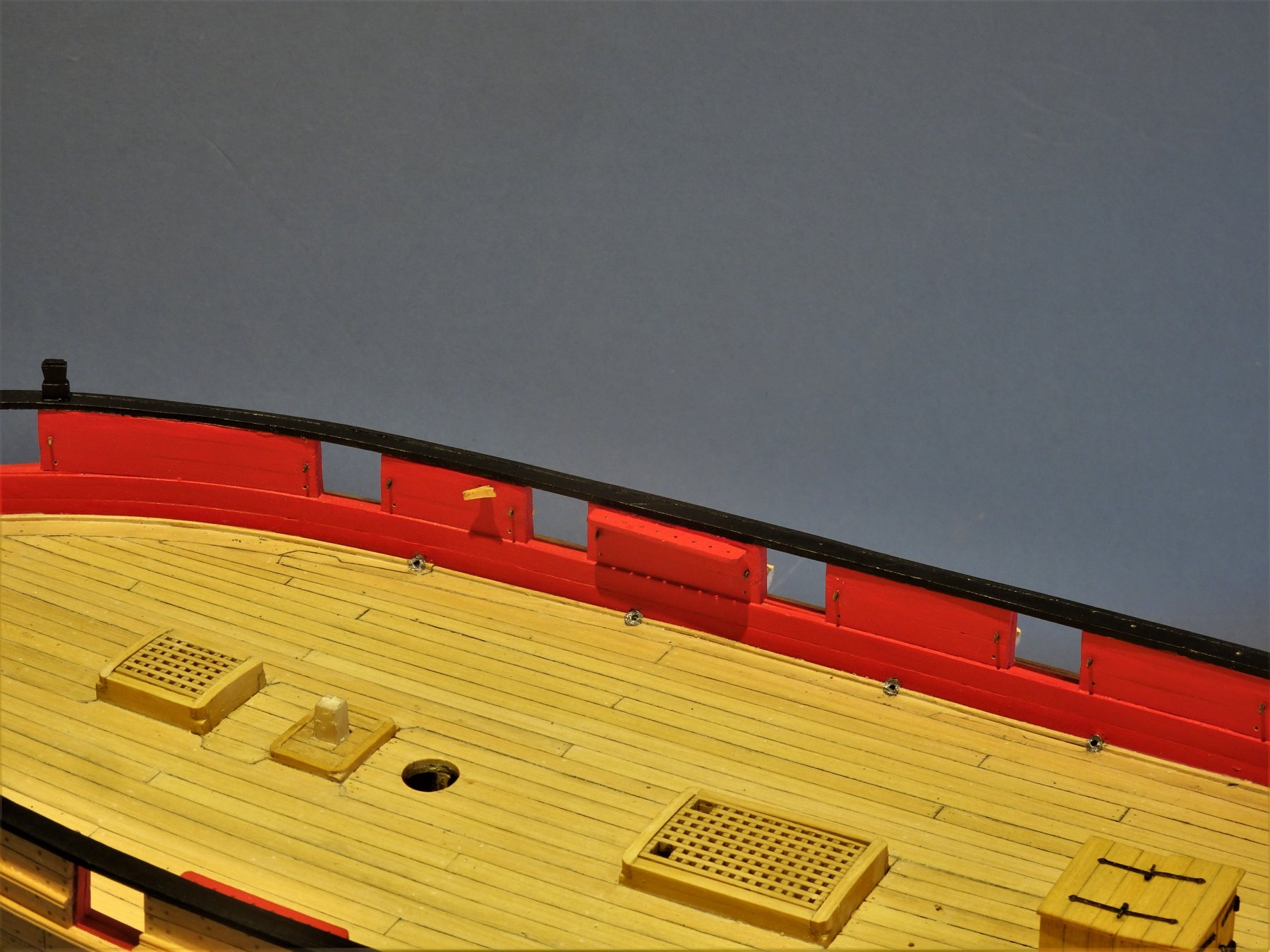
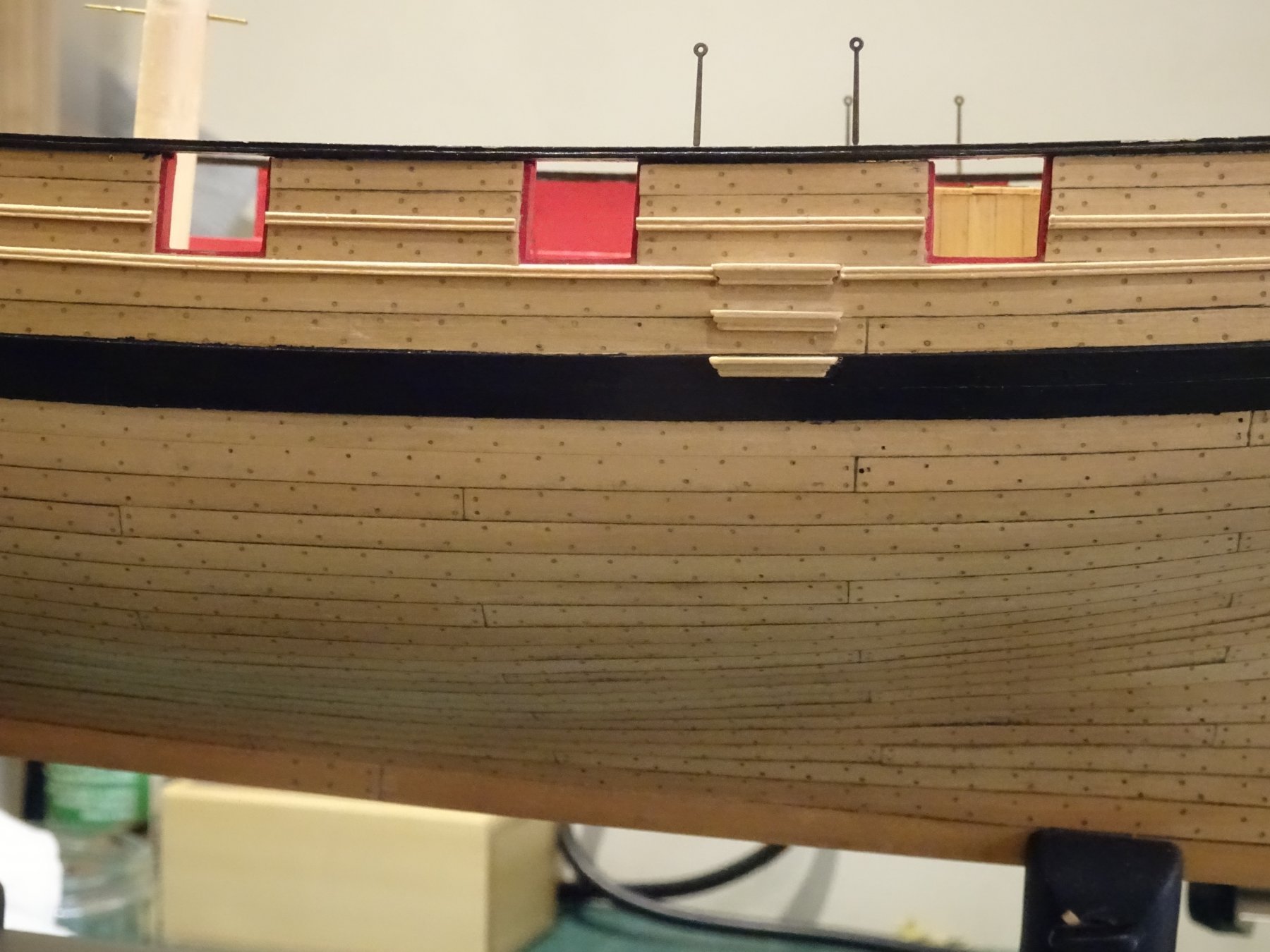
Thank you for your comments kirill4 and OC, much appreciated. Post 66 Continuing outboard Thinking about Scuppers On Cheerful there are four of them running along the hull with the outlets sited just above the wale. As far as I can see from the plans the scuppers are 1.5mm in the clear. I'm certainly not brave enough to drill the holes straight thro' the hull so mine will be false scuppers. Scuppers weren't just downward sloping holes drilled thro' the hull they were lead lined pipes exiting the hull thro' a specific block fixed between the frames, with flanges turned on either end. I wished in some way to at least replicate the flanges. 5818 The answer came in the form of brass hollow eyelets with a thickness of 0/1mm, 1/16th" dia and 3/32" length. I remembered that I had originally bought these for use on Pegasus but they proved a tad too large for 1:64 scale, but for Cheerful at 1:48 just about right. 5813(2) The scuppers were chemically blackened before a push fit into the hole. 5809 So far so good, I'm happy with the outlets. The internal scuppers are far more tricky with the flange fitting; part on the margin plank and part on the waterway, running to the spirketting. I take my lead for the internal scupper arrangements from David Antscherl's FMM book Vol 11. Drilling the internal scuppers needs care to avoid splitting the very fine waterway strip. I spent a day forming the flanges from slices of aluminium tubing, hammered a little, and squeezed to form an oval shape. 5852 As I thought fitting proved tricky, but in the end I didn't like the effect. I thought they looked too prominent, so off they all came. Approach 2 involved stamping flange shapes from a sheet of 0.1mm thick lead foil sheet. This was more promising as the process was quicker and the flanges moulded closer to the profile. 5879 5876 These are in a raw state but already they look more in scale and less prominent. 5888 5883 5875 I will leave these to allow for natural patination before I consider a coat of flat grey paint. Time to consider the Chain and Backstay plates. B.E 07/02/2019

.thumb.JPG.e30bee241327d98b82fa3ebb98d19cf6.JPG)


- 574 replies
-
- 28
-
-
- cheerful
- Syren Ship Model Company
- (and 1 more)
-
The breeching rope thro’ the gun carriage is correct for French ships, whereas on British ships it passed around the cascobal or thro’ the breeching ring on later pattern guns. B. E.
-
Thanks for looking in Jorgen, I'm quite impressed with the Vallejo paint, it has great consistency, thins beautifully, and very economical to use. I initially bought three bottles, unsure how much Cheerful would take, but I've still got plenty left from the first bottle. Regards, B.E.
- 574 replies
-
- 3
-
-
- cheerful
- Syren Ship Model Company
- (and 1 more)
-
My eye does keep getting drawn to that space above the third step, eventually I may succumb and add a fourth along the line of the top moulding. Only downside is that I would have to mill a complete new set to get the profiles the same. Not all sources agree Jason that there were hand holes cut into the entry steps but Peter Goodwin shows them in his Cutter Alert Book, and Victory had them, I thought them a nice detail, and besides getting aboard Cheerful seemed difficult enough😉 Cheers Dave, as soon as I received Chuck's mini anchor kit I thought 'too early for Round Crown' . I will be fitting an Admiralty pattern anchor; Caldercraft have a good range, one of which will suit, but that's some way off at present.🙂 Cheers, B.E.
- 574 replies
-
- 2
-
-
- cheerful
- Syren Ship Model Company
- (and 1 more)
-
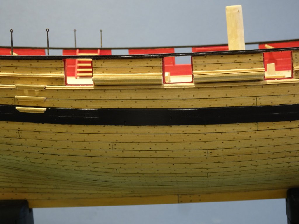
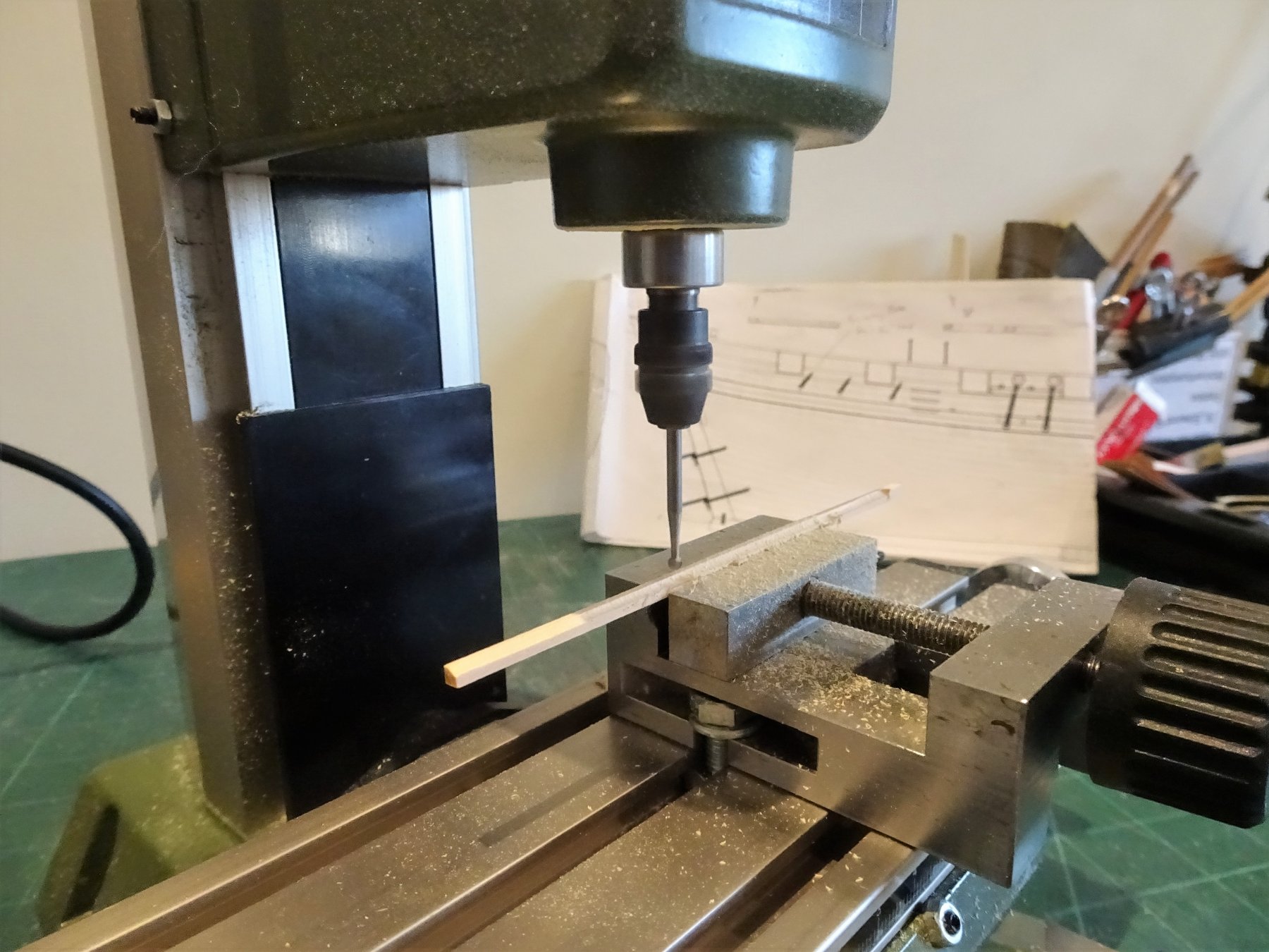
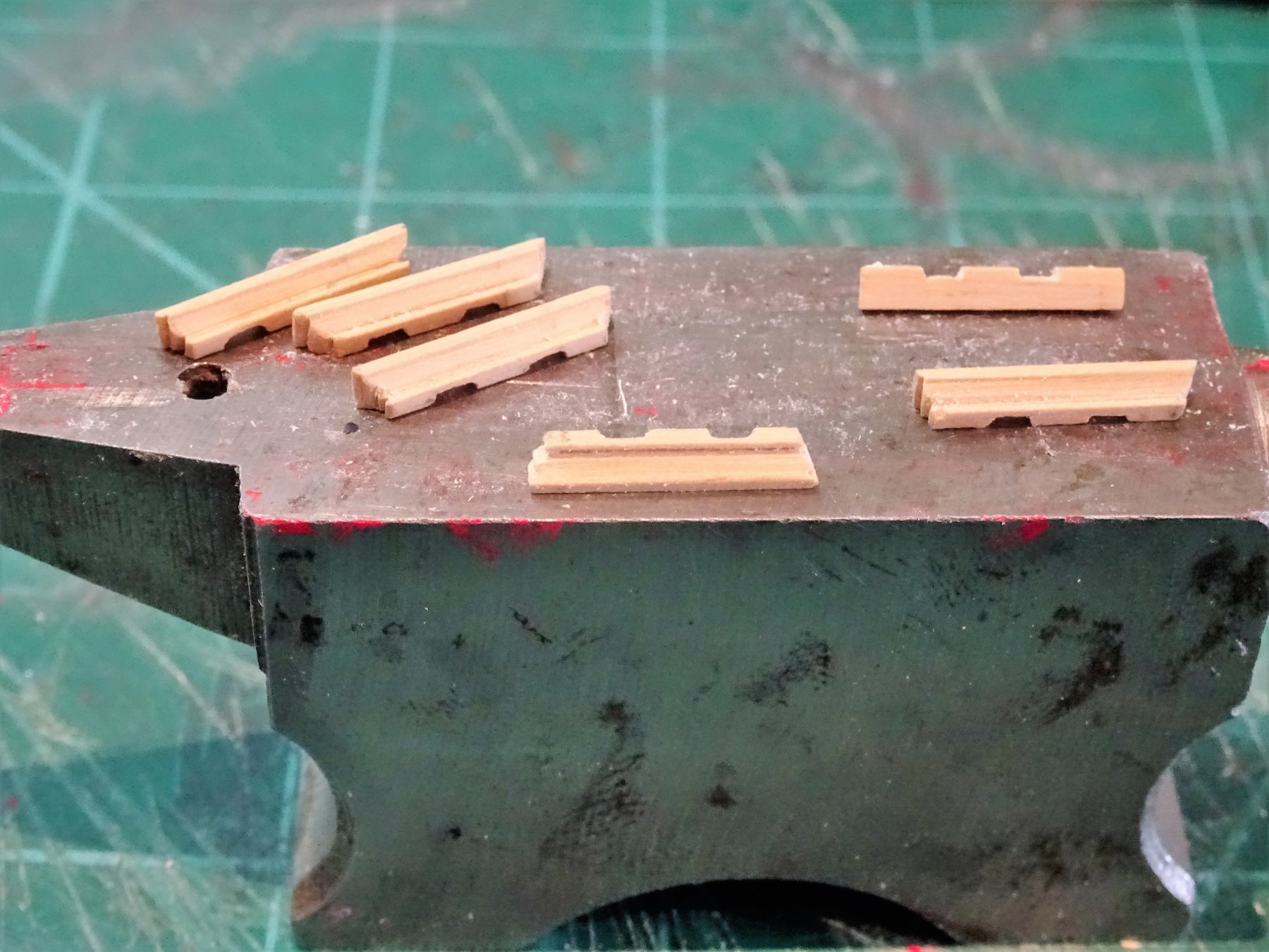
Post 65 Returning outboard Side steps and Channels Surprising how much time producing these seemingly innocuous little fittings take. There are three of these each side aligning with the inboard steps. They are formed from 3/32" x 3/32" Boxwood strip as indicated by Chuck. 5762 I decided to mill the profile rather than use the 'scrape' method but I first had a practice on slightly larger stuff. 5764 5770 Ready for fitting. I fit them in the order of top, bottom, and middle, taking care not to damage the moulding when removing a section to allow the top step to fit in. 5773 The 'iron' stanchions are only temporarily fitted at this point to help align the inboard and outboard steps. 5779 The question has already been discussed on Chuck's log as to why no fourth step. My eye screams at me that one should be there, along the line of the top moulding strip. Only three are shown on the NMM original plans, so three it is, but my eye still screams at me. 5787 Channels These are made from 5/32" x 5/32" strip as indicated by Chuck. Having marked the profile I used the little miller to produce the shape. 5790(2) 5797 The end profile was formed used a scalpel and mini round file. 5801 I decided to leave cutting the slots until later when I had a better idea of the Chainplate angles. 5804 Little by little getting there. B.E. 05/02/2019


.thumb.JPG.f3562c83b78e2e204e81ff93b88ae433.JPG)
- 574 replies
-
- 27
-
-
- cheerful
- Syren Ship Model Company
- (and 1 more)
-
A beautiful build Rusty, great stuff👍 B.E.
-
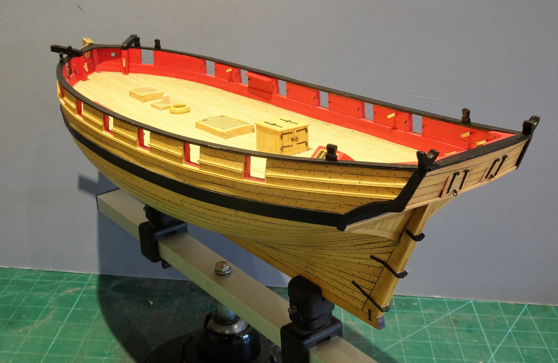
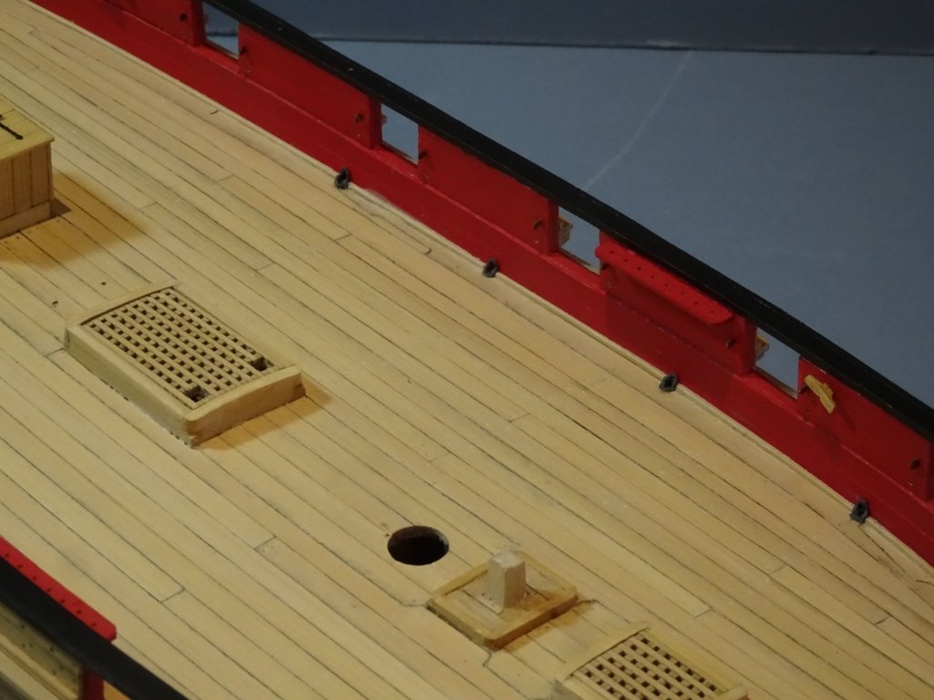
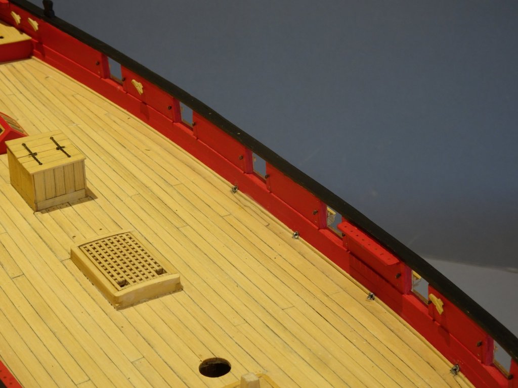
The coamings are glued to the ‘false deck’, the deck planking is then laid. B.E.
- 574 replies
-
- 1
-
-
- cheerful
- Syren Ship Model Company
- (and 1 more)
-
I think you're right Dowmer, having pre-made the hatch surrounds to the plans as I thought, I obviously didn't take the round down sufficiently to the deck level, and then forgot all about it as I moved onto other stuff. Thanks for the heads up, we need more members to point things out that puzzle them or don't seem right to help keep us on track. B.E.
- 574 replies
-
- 8
-
-
- cheerful
- Syren Ship Model Company
- (and 1 more)
-
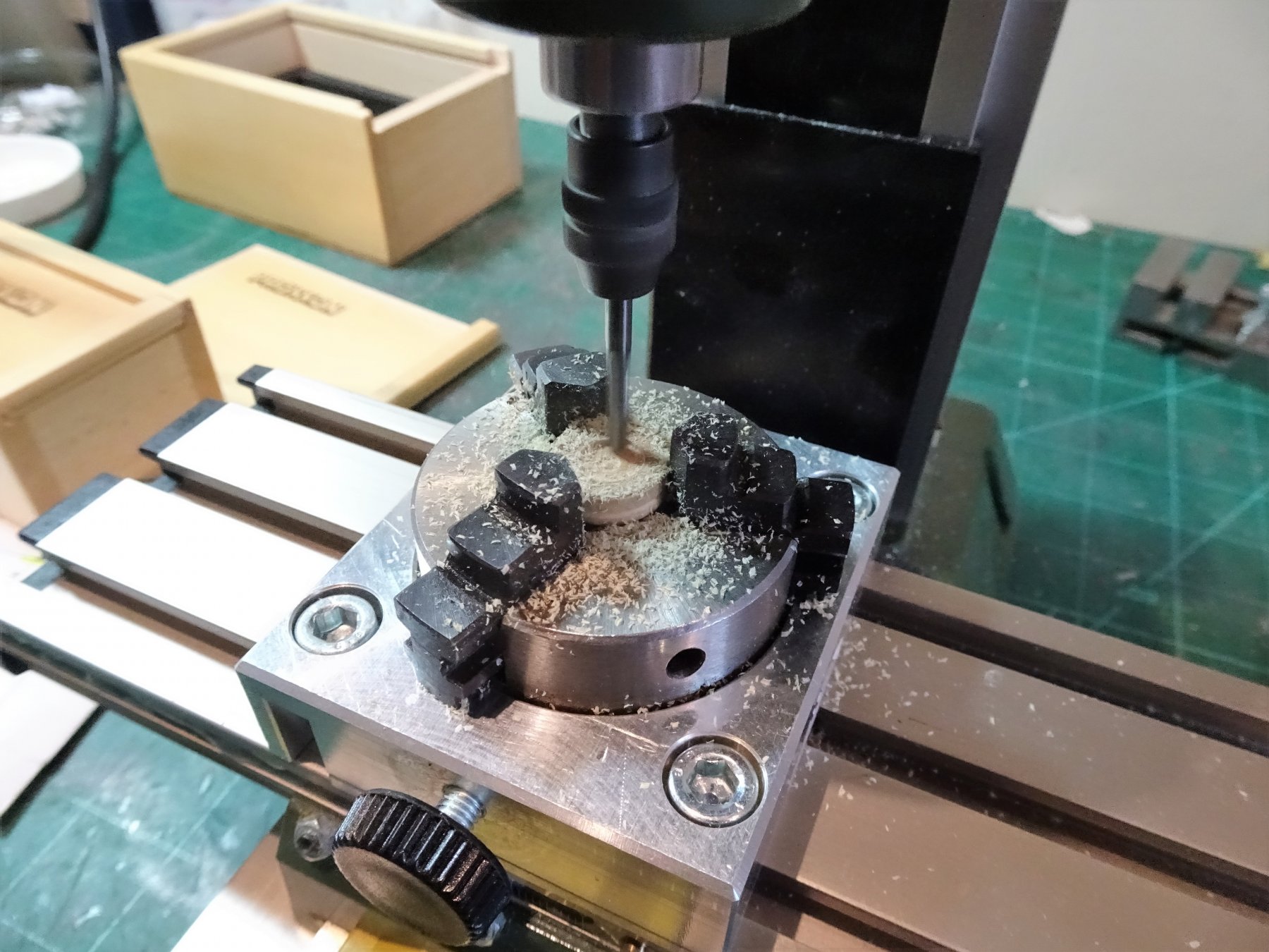
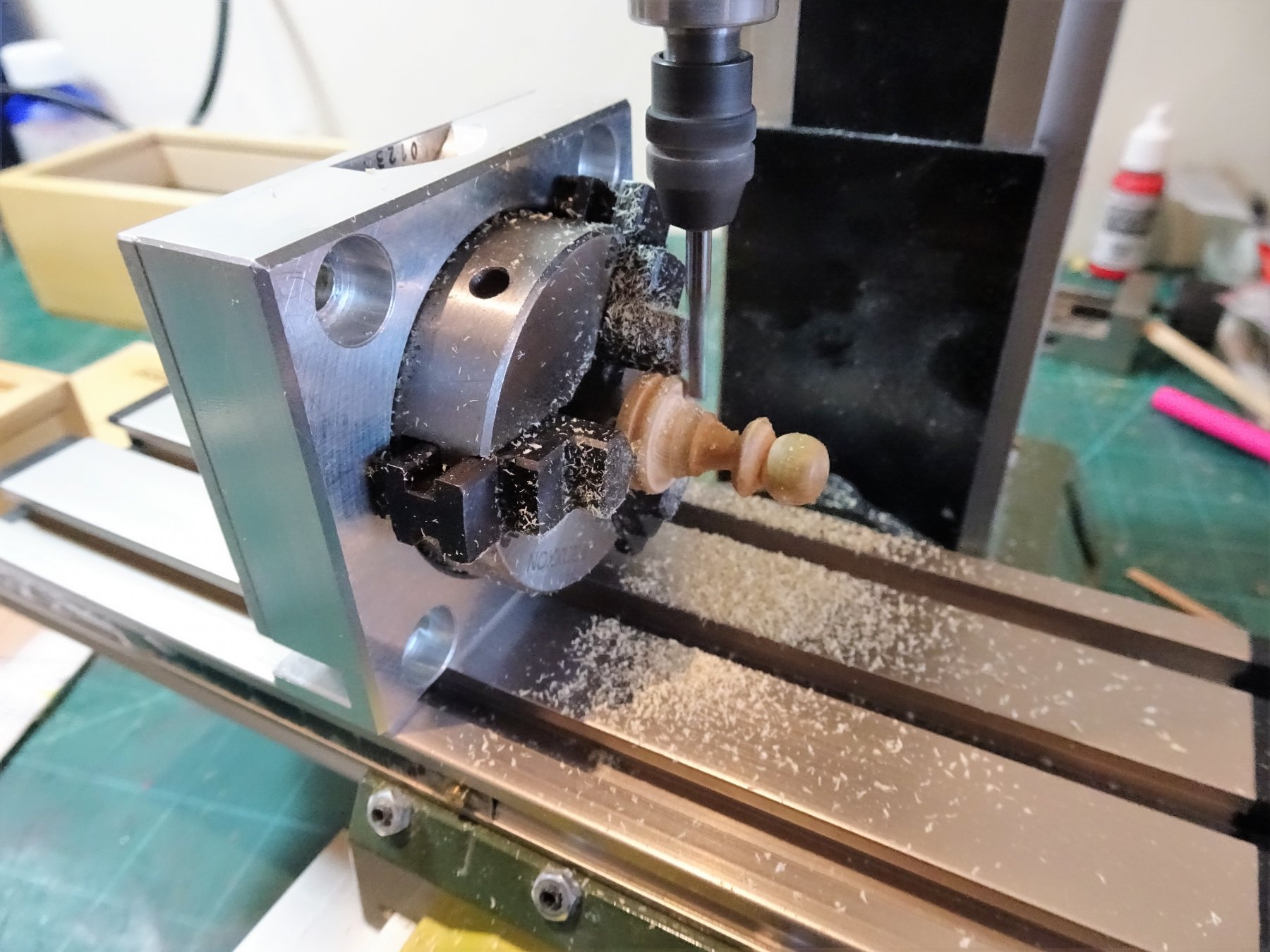
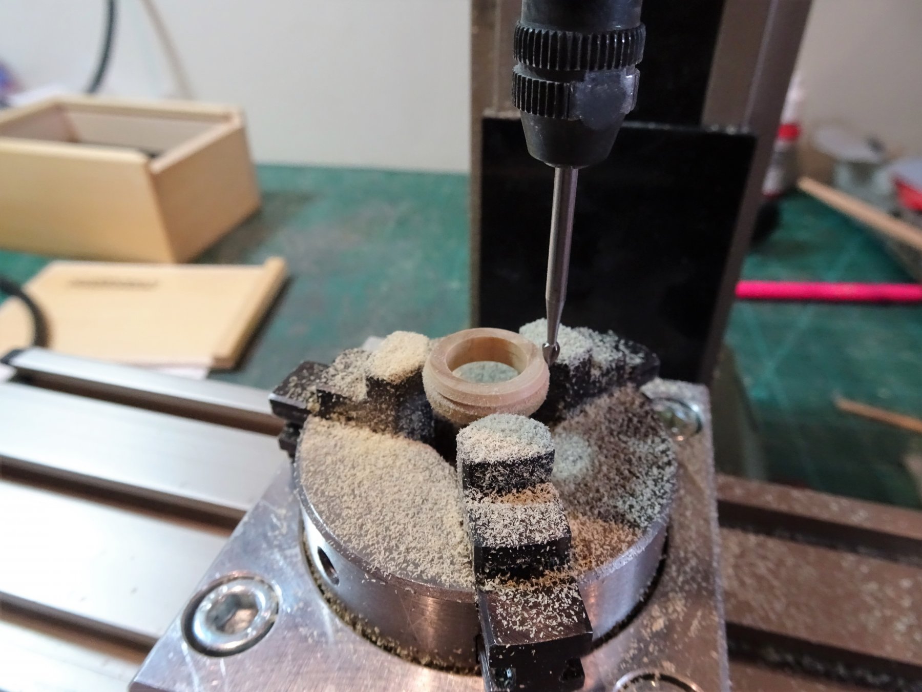
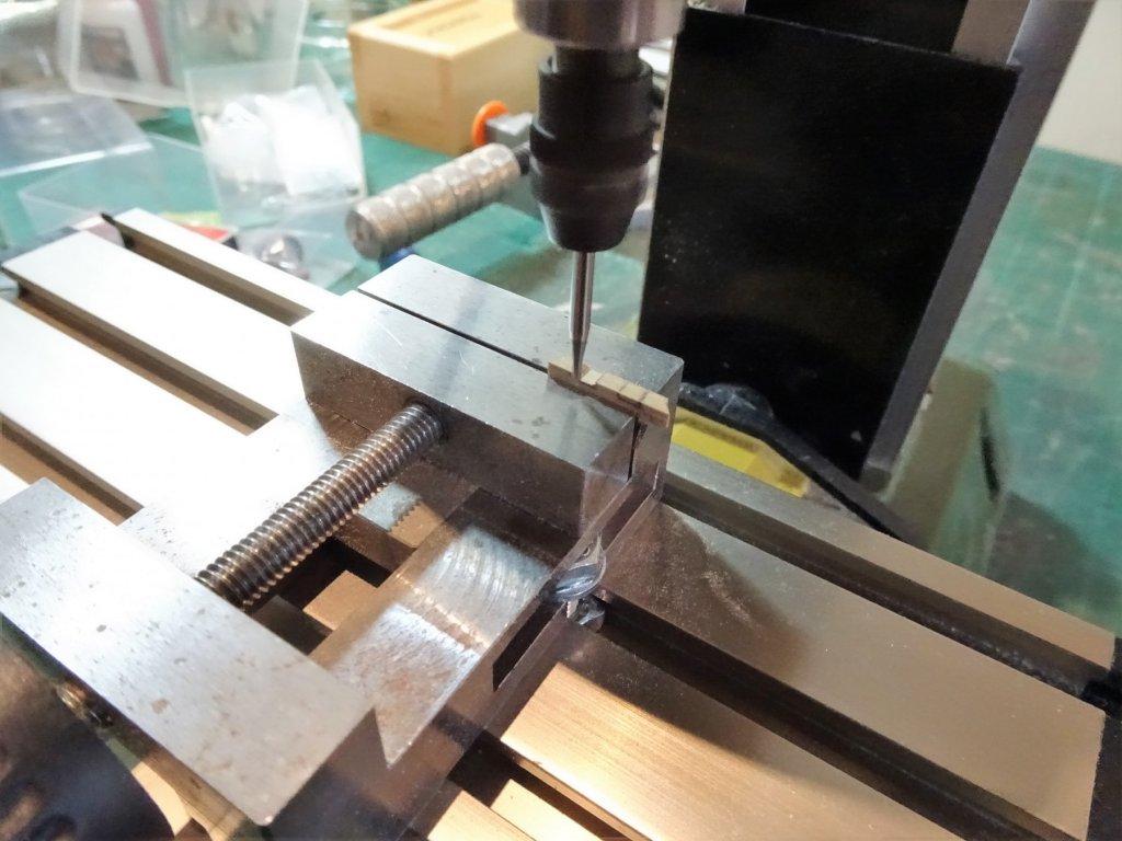
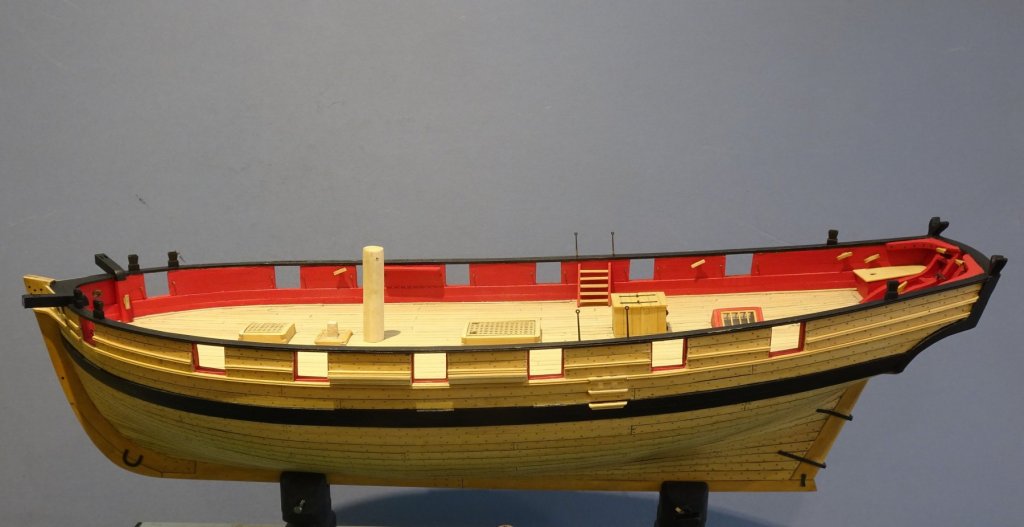
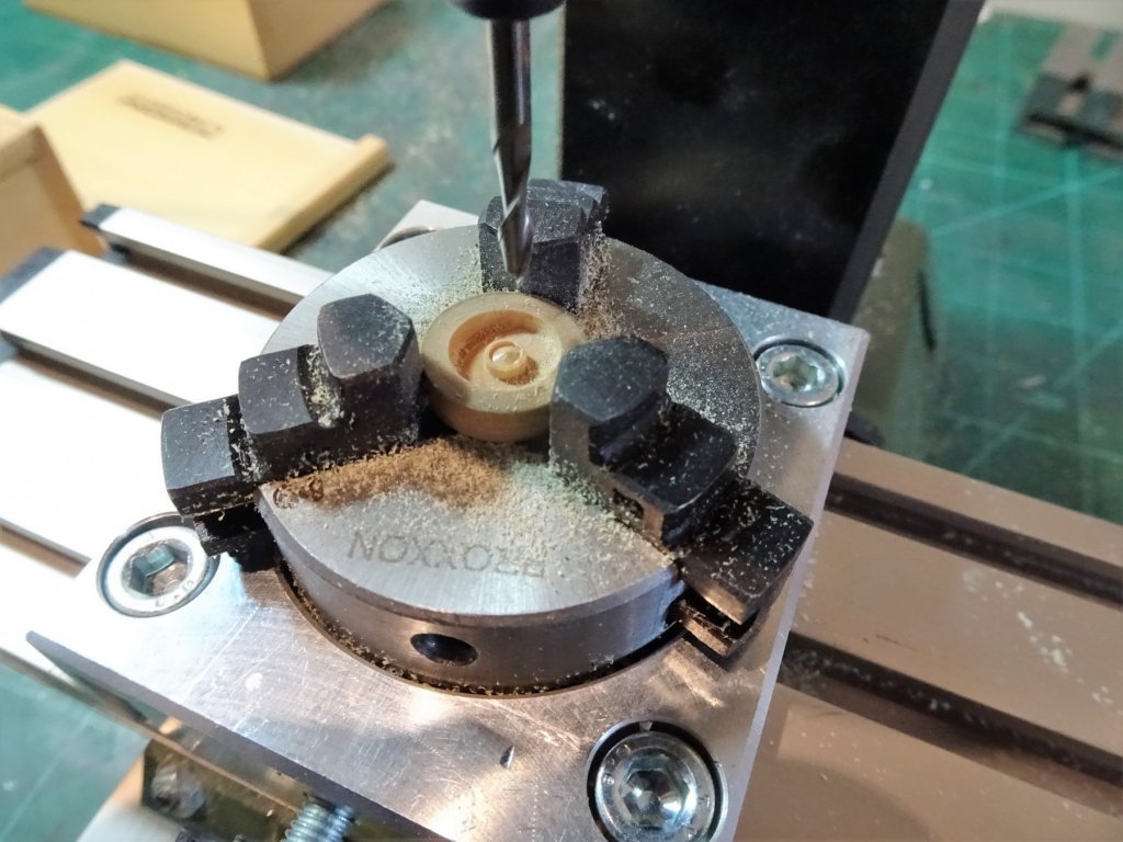
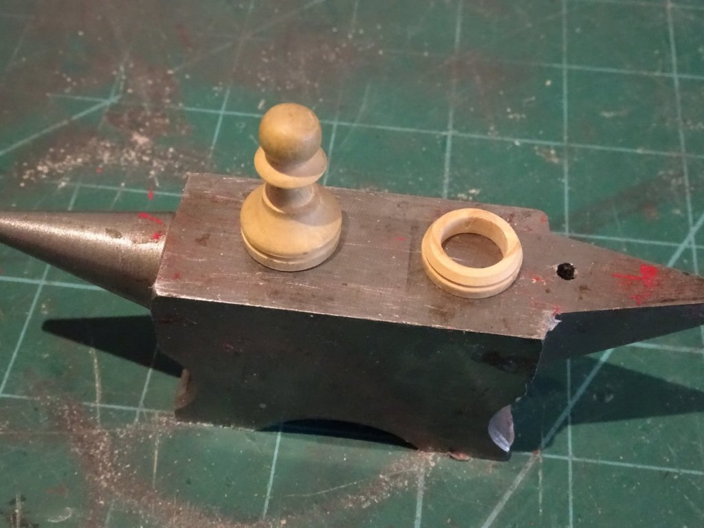
Post 64 Mast Coat This is the last deck fitting I need to make. Have been thinking about it for a while and I didn't fancy trying to drill and shape this boxwood ring by hand. So for this little exercise I got the mill out. 5735 I also brought into use the Dividing head to remove the centre. 5736 The beauty of this tool is that it can be used in either the horizontal or vertical plane. 5737 This gives a clue as to the donor for the mast coat. 5739 Shaping the rim is the final operation. 5741 Not for the first time an old Boxwood chess piece has provided the makings. 5746 5755 5754 A little more tidying up and another milestone sort of reached. 5760 Meanwhile the precious little boxes of fittings delight await their turn. That about does it for the present, now returning outboard. B.E. 01/02/2019


- 574 replies
-
- 22
-
-
- cheerful
- Syren Ship Model Company
- (and 1 more)


.JPG.ae101f230bda3204409496fbe052b369.JPG)
.JPG.37f557b0739abde68dce77562df91b81.JPG)

.JPG.64244a6ecc78647be8157f3c66f454a4.JPG)
.JPG.9476461f174d0755bfcc7144405e27d1.JPG)

.JPG.fbbc64e3b9e30bd701ff523df463599c.JPG)


.JPG.7d96a822646c33578a19313e7c50239a.JPG)


.JPG.db33fe1d7c8aa6e80f2a91d43ee1e275.JPG)