.JPG.ca33079f5815b861e67b9c2cccd37982.JPG)

Blue Ensign
-
Posts
4,571 -
Joined
-
Last visited
Content Type
Profiles
Forums
Gallery
Events
Everything posted by Blue Ensign
-
 Received today my copy of the second volume of the Rogers Dockyard Models covering Third rates. Another beautifully presented book, and a worthy addition to my library. Excellent service, 11 days from order to door,USA to UK. Thank you Bob and Cathy. B.E.
 -
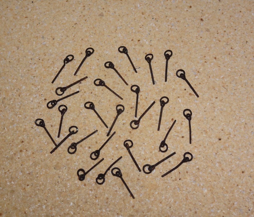
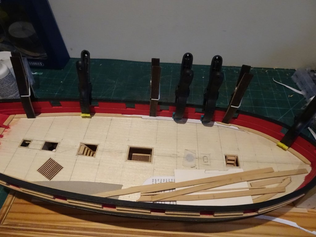
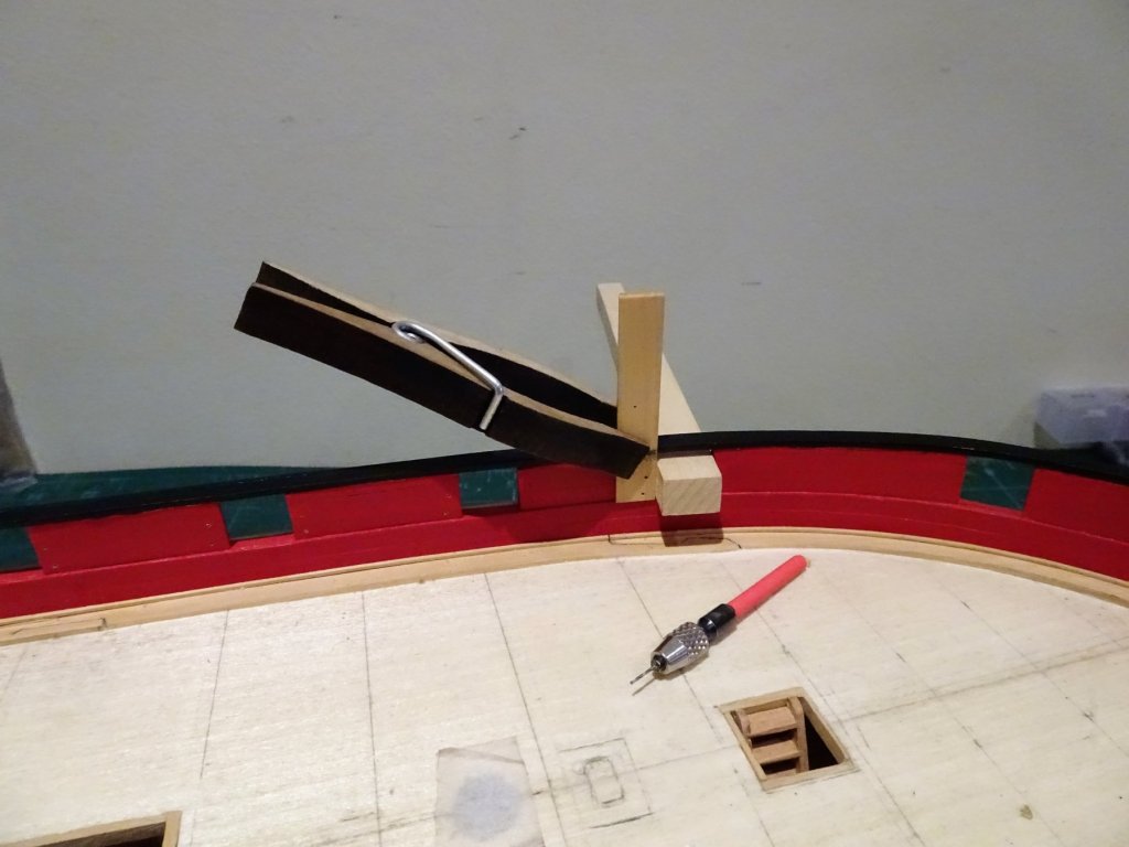
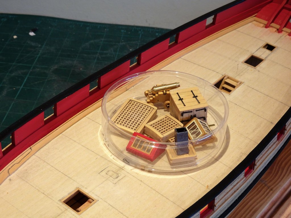
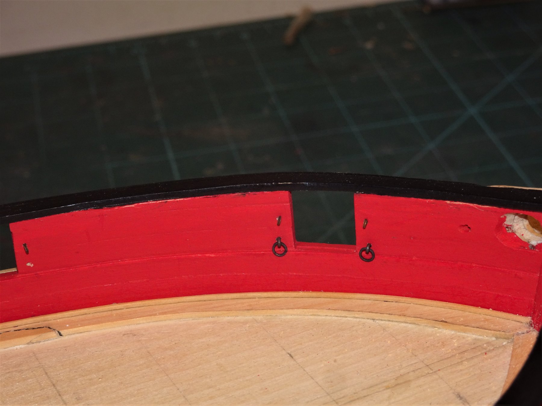
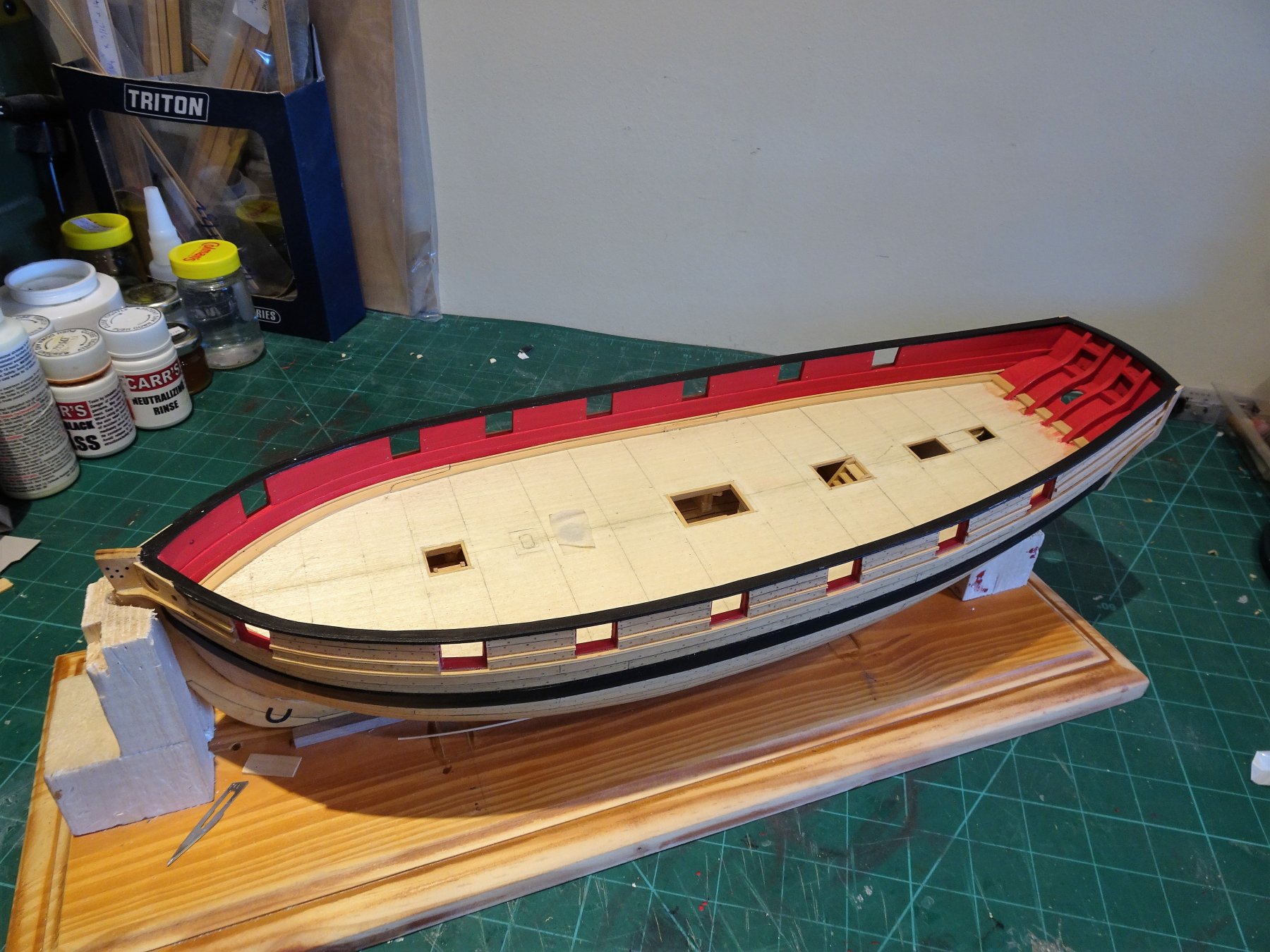
Post 50 Thinking about Gun tackle scales Fairly early in the stage, but I will fit the tackle eyebolts along the bulwarks and ensure that the holes for the breeching ring bolts are sufficiently deep and of the correct size to smooth the fitting later around all the encumbrances that will be on the deck by then. I am conscious the more stuff on the deck the more difficult it is to get the drill square into the bulwark. Chuck indicates using 28 gauge wire for the eyebolts and 24 gauge for the breeching tackle rings. I presume he is referring to AWG and not SWG which we are more familiar with in the UK. There is not a huge difference but AWG is finer than SWG by equivalent gauge. AWG 28 = 0.3211mmØ SWG = 0.376mmø AWG 24 = 0.5106mm Ø SWG = 0.599mmø I recall from my Pegasus build; Breeching rings: 1"ø 4" in the clear at 1:48 scale:= 0.5mm ø 2mm internal ø Port Tackle eyebolt: 1"ø 1¾" in the clear at 1:48 scale:= 0.5mm ø 0.92mm internal ø For the Breeching rings I used 0.5mm ø brass wire wrapped around a 2mm drill bit and snipped. A spot of silver solder secured the join. I went this extra step to reduce the risk of a ring failing and simply because I fancied doing a spot of silver soldering (or brazing as us professionals properly call it) 😉 For the bolts that hold them an eyebolt will suffice, modified slightly. 4557 Once cleaned up, the assembly is chemically blackened. 4569 4566 Apart from the forward port-side port where I don't intend to fit a gun, I will defer fitting the other ring bolts as it will be easier to pre-attach the breeching rope before they are inserted into the bulwark. With a short stub stem I find these things tricky to fit at the best of times, and the risk of marring the bulwark paint is high if the fitting hole isn't a clean fit. Time to start scratching my head over decking. 🙄 B.E. 15/11/2018


- 574 replies
-
- 10
-

-
- cheerful
- Syren Ship Model Company
- (and 1 more)
-
Another fine build Rusty, and one I also have beneath the bench for when I finish Cheerful. Your models are an inspiration, and a pretty hard act to follow😊 B.E.
- 120 replies
-
- 2
-
-
- queen anne barge
- Syren Ship Model Company
- (and 1 more)
-
I too would opt for the heavier breeching line, it appeals more to my eye. I also like a clear distinction between that and the side tackles. Worth looking at the two elements together before making a final decision. Regards, B.E.
-
Thank you Wallace. B.E.
-
Thanks Wallace for looking in, and for your kind words.☺️ B.E.
- 574 replies
-
- 1
-
-
- cheerful
- Syren Ship Model Company
- (and 1 more)
-
Hi Paul, I got it from Jason at Crown Timber yard when I ordered the original timber package. I have in the past few months had another order from Jason of some wider Boxwood Strip, and he provides a good service. Regards, B.E.
- 574 replies
-
- 2
-
-
- cheerful
- Syren Ship Model Company
- (and 1 more)
-
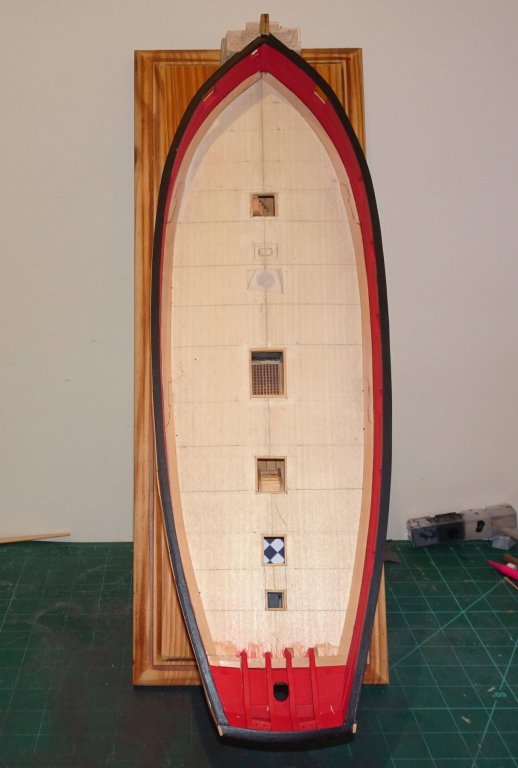
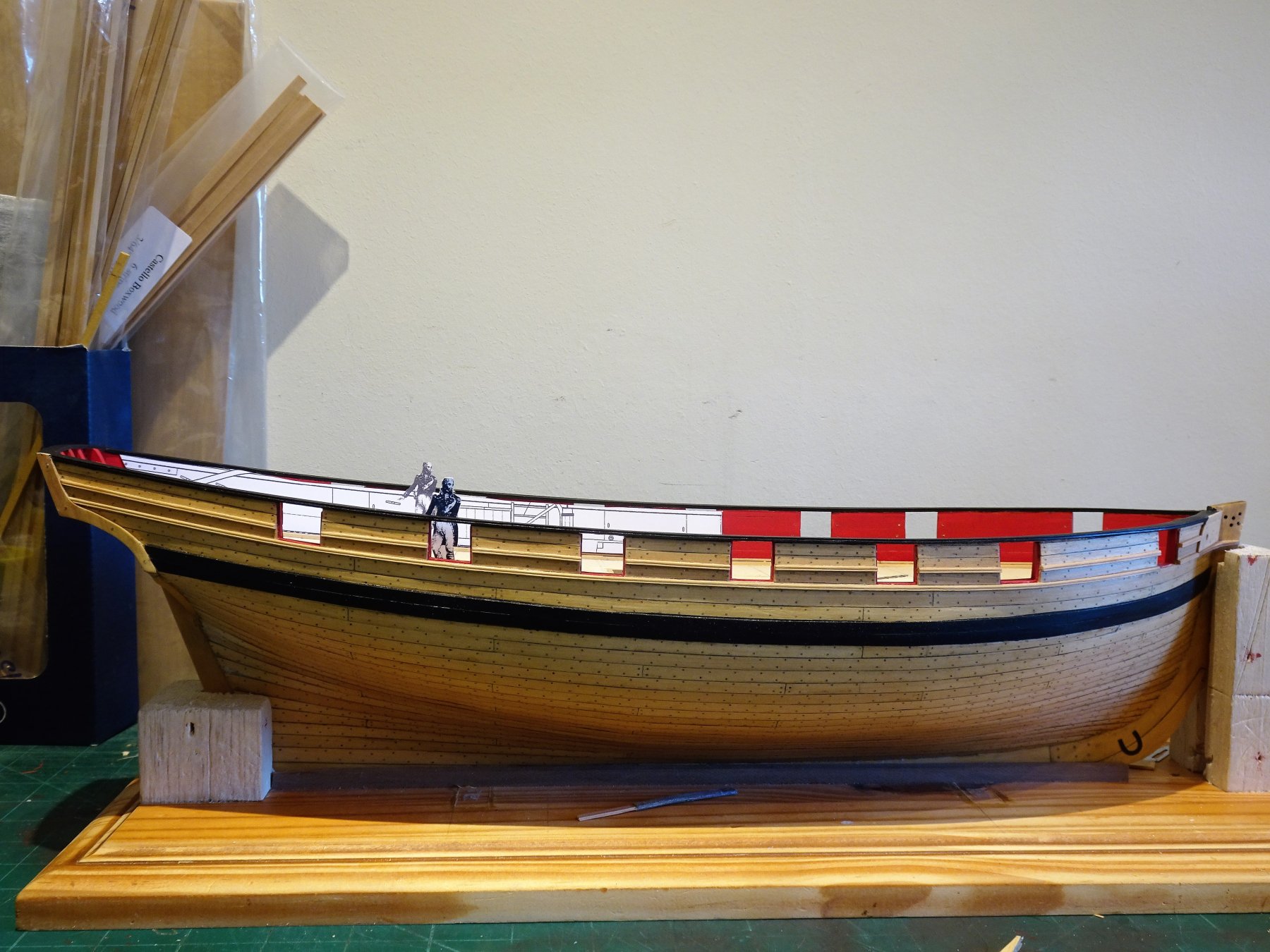
Thanks Dave, mine is the same, so that is a relief, just had a moment of doubt. The scale figure is 35mm = to a height of 5'6" which is appropriate. 4548 Still I needed to cut out the figure and the inboard plan to convince myself. Not too far out I'm relieved to say.🙂 B.E.

- 574 replies
-
- 6
-
-
- cheerful
- Syren Ship Model Company
- (and 1 more)
-
Thanks Dave, can you tell me what the height is midships between the deck and capping rail top on your model? I’ve been looking at the scale figure on the plan and the capping rail top on my Cheerful appears higher in relation to a 1:48 scale figure but I can’t figure out why. 🤔 B.E.
- 574 replies
-
- 1
-
-
- cheerful
- Syren Ship Model Company
- (and 1 more)
-
Looks a fine kit Steve, one thing you won’t need is the Union Flag at the main masthead. 😊 B.E.
-
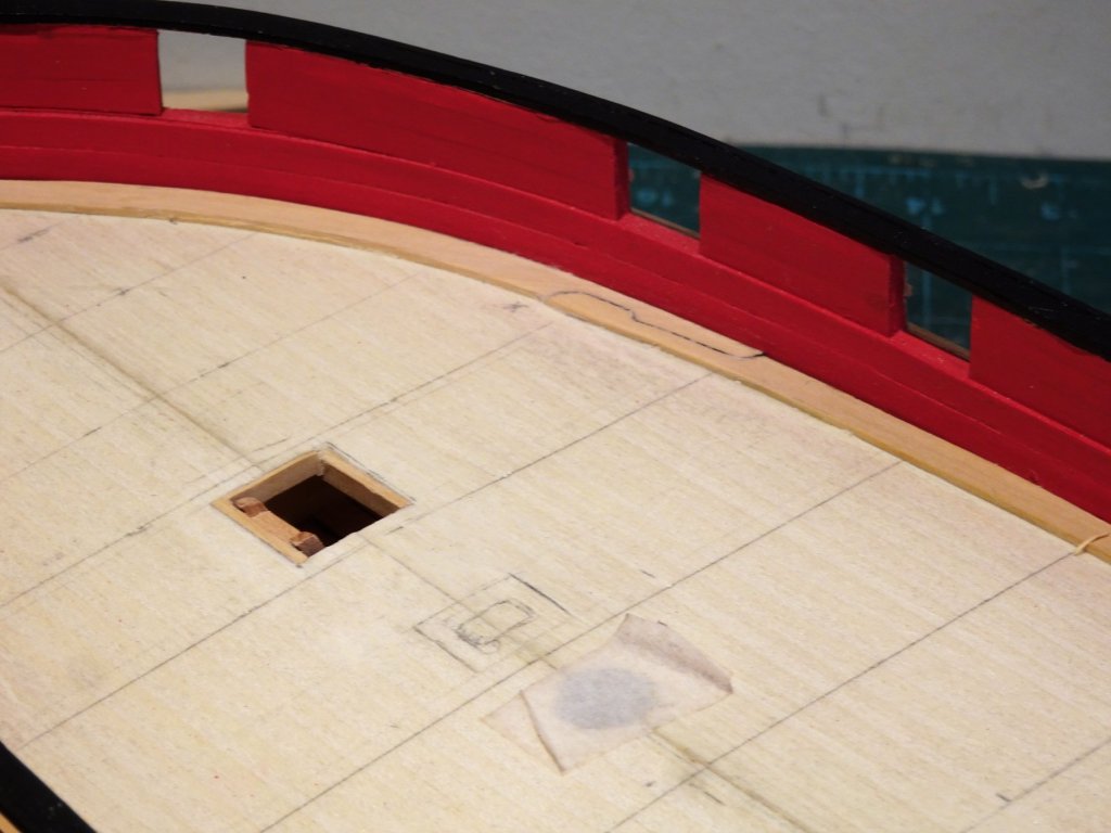
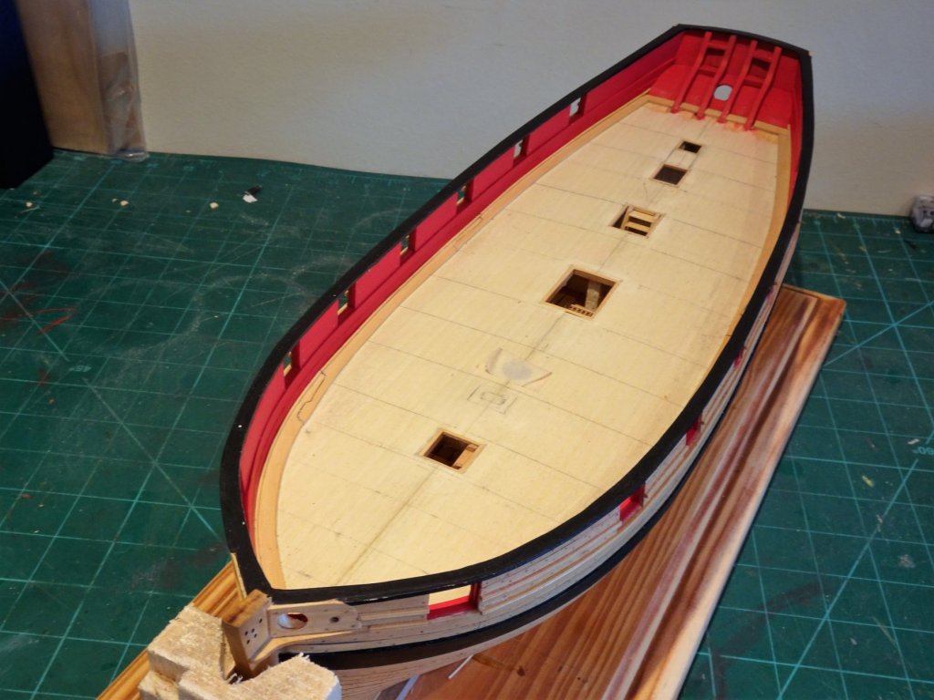
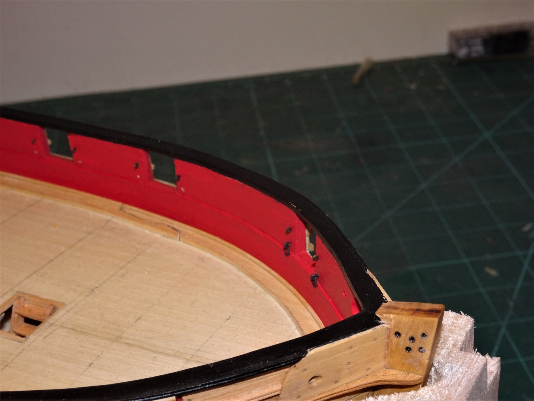
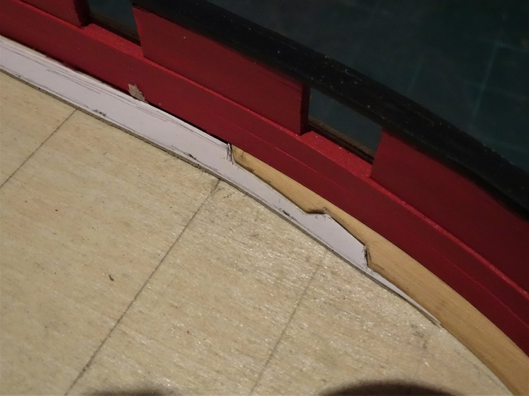
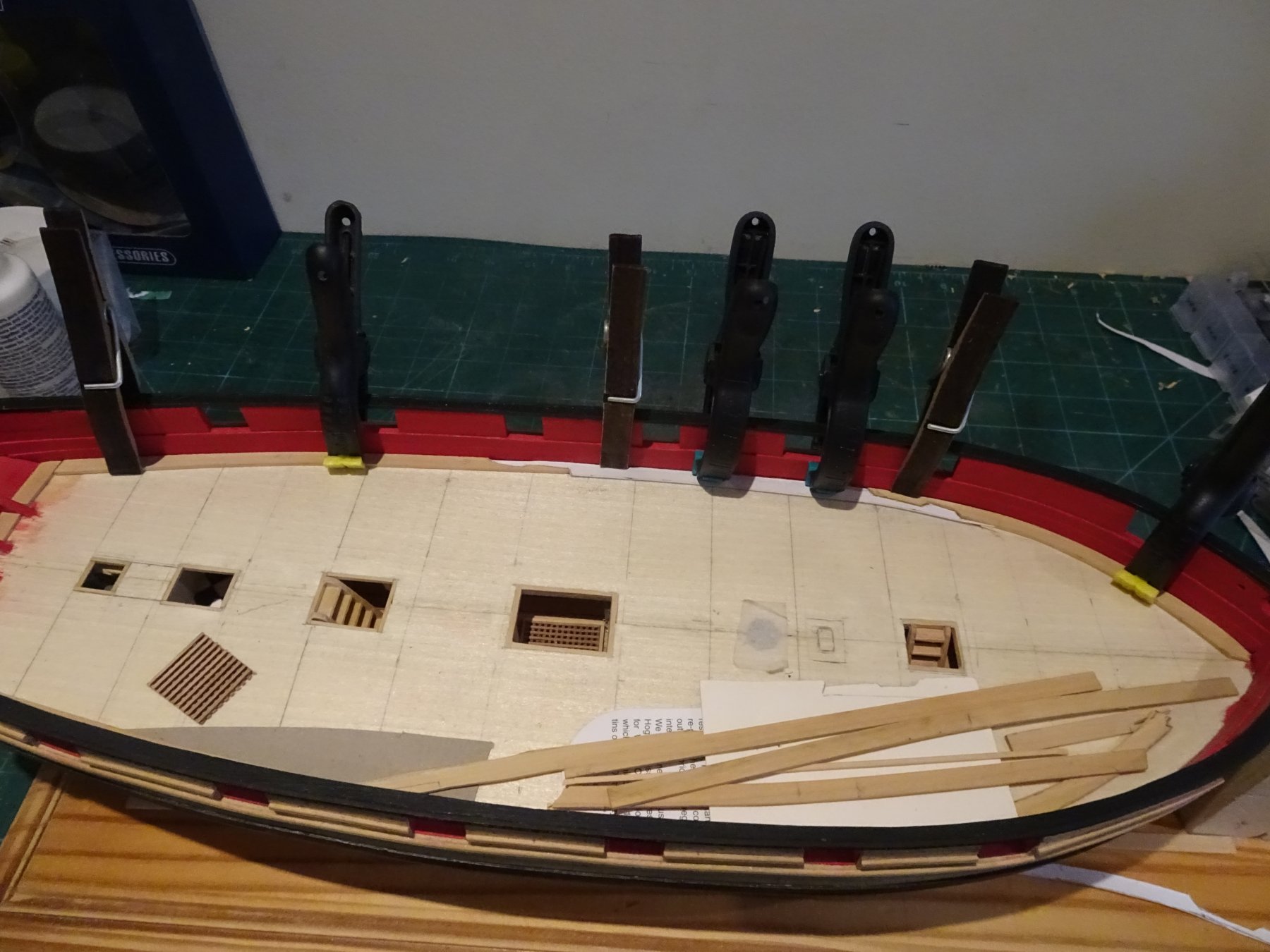
Post 49 Margin for error? In accordance with the plan the Margin plank is fitted in three sections joined by scarph joints. The short sections between the stern frames were fitted first using 3/64" x 1/4" strip. There seems to be a little variation for the positioning of the scarphs between the supplied plan and the build instructions. The plan shows quite a short Bow section whereas Chuck has it extending aft past the second port in his build, which seems to me a more manageable arrangement. I am using 3/64" x 1/4" strip for the aft section of the margin, heat bent and with the scarph then cut with a No 11 scalpel. I have terminated this section just past the third port from aft. The more tricky bow section was cut from 3/64" sheet using a card template. 4133 With the Bow and stern sections temporarily in place a card template can be marked with the scarphs for the centre section which is then cut out from the 3/64" sheet. 4134 Took quite a bit of time faffing around with these sections. 4156 4159 On reflection I suppose I could have used a simpler form of scarph The final piece is the Waterway for which 1/32" (0.8mm) square stock is called for, rounded on the top edge. This seems incredibly small, at full scale a mere 1 1/2" 4534 Try as I might I couldn't get consistent widths cut from a 1/32" sheet, at the required lengths, so I took the easy way out and ordered some 1/32" square stock from Chuck. 4531 My main concern with fitting the Waterway was not to get glue over the painted Spirketing, so I used a fine smear of glue and had water available to immediately clean any excess. 4532 A growing collection of mini delights. This is a convenient point to drill the holes to take the bulwark eye and ring bolts, before the deck gets cluttered. 4508 Taking the positions from the plan a simple hole guide jig is used to mark the bulwark. In practice the upper gun tackle eye bolts are 7mm above the spirketing and 2mm in from the port edge. The Breeching rope ring bolts are 2mm above the spirketing and 2.5mm in from the port edge. 4528 Time now to think about the decking. B.E. 11/11/2018


.thumb.JPG.55582fd4ebc9ad667651b5f27392da32.JPG)
- 574 replies
-
- 15
-
-
- cheerful
- Syren Ship Model Company
- (and 1 more)
-
Hi Dave, I admire you're resilience in scratching those gun carriages.👍 Re the Swivel posts; I think 3/16" square stuff is too heavy, but 1/8" looks about right, and fits on the capping rails as a timber head extension quite well. The 1:24 scale drawings of the swivel posts in The Cutter Alert book, has them at 6.36" which is a tad over 1/8" at our scale. I think I will go with 1/8" square stuff. Thanks Martin, I have decided to go with the Red version. No plagiarism on here Martin, just a mutual development of ideas to advance our obsession.☺️ Thank you Thomas, I do enjoy playing with the fittings, far more than the basic construction stuff. Cheers, B.E.
- 574 replies
-
- 2
-
-
- cheerful
- Syren Ship Model Company
- (and 1 more)
-
Very nice result Tomek, such a lot of fine detail in a model so small. Well done.🙂 B.E.
-
I would agree Steve the kit supplied blocks for the bijou carronades are over scale. I used 2mm versions from the now defunct JB Models, today I would use Syren versions. I think the rigging line sizes for the guns also needs looking at, there does need to be a visible difference between the side tackle lines and the breaching rope. 0.1mm dia line for the tackles is more than enough. Line isn’t the only issue when rigging these guns, getting tiny seizings is also problematic. I cheated on my build using fine wire and frapping to try and get a scale appearance. One thing I find with many kits is that the mast and yards are too heavy for the scale and could do with fining down somewhat. Regards, B.E.
-
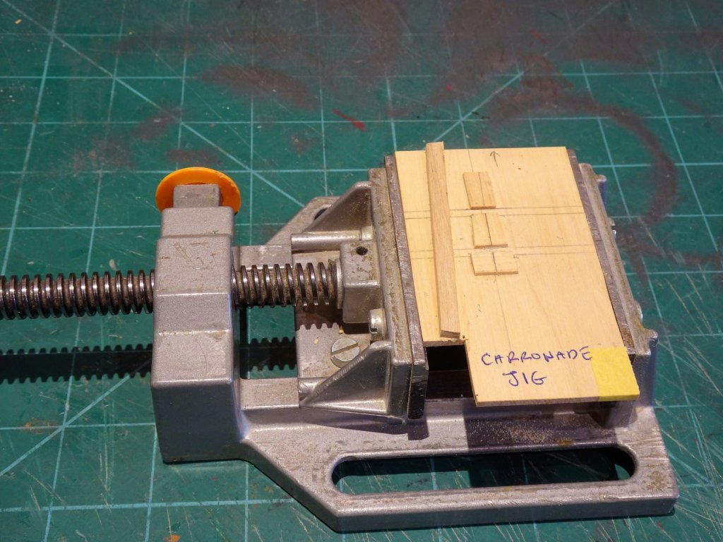
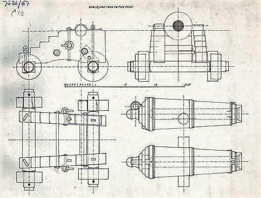
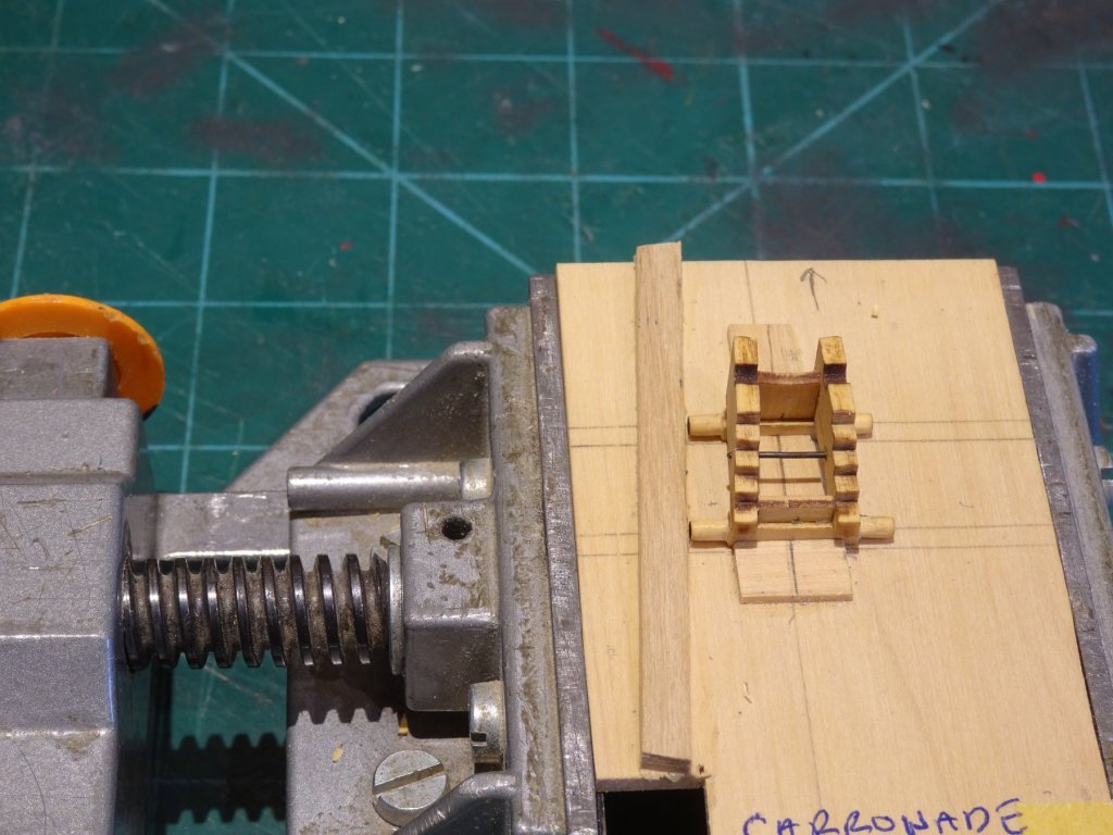
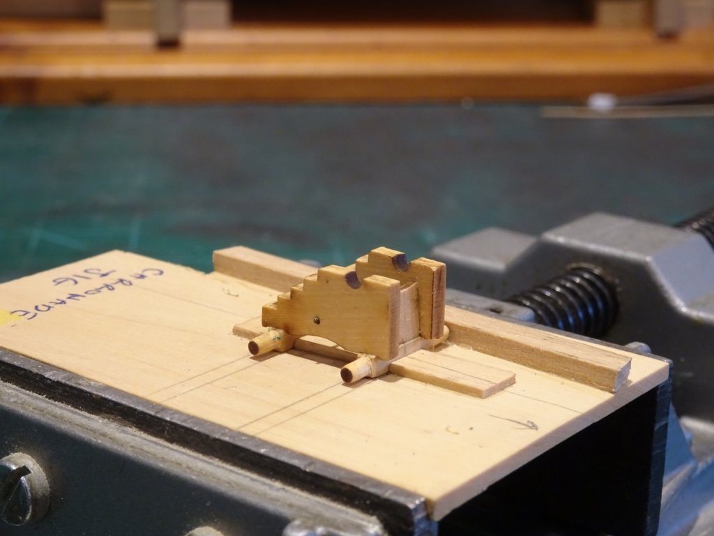
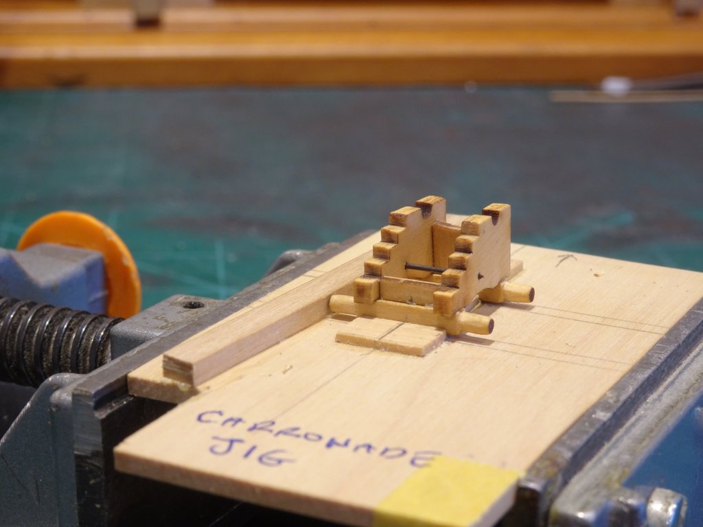
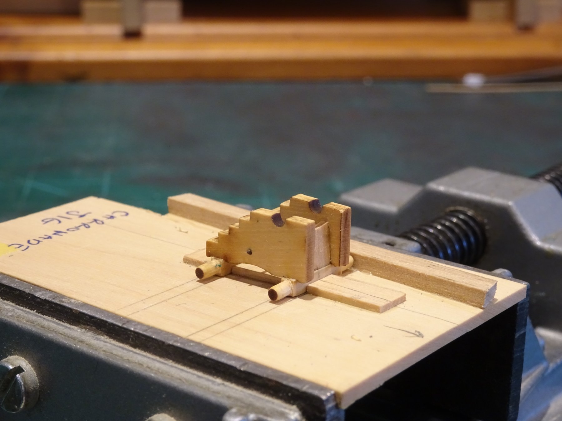
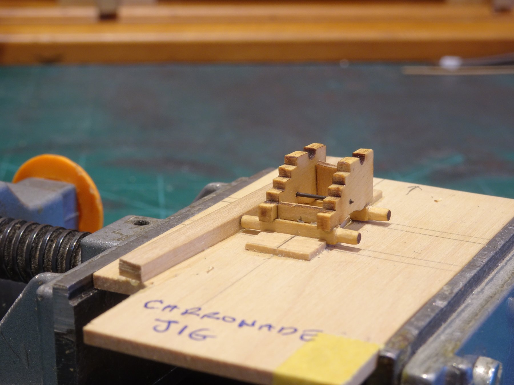
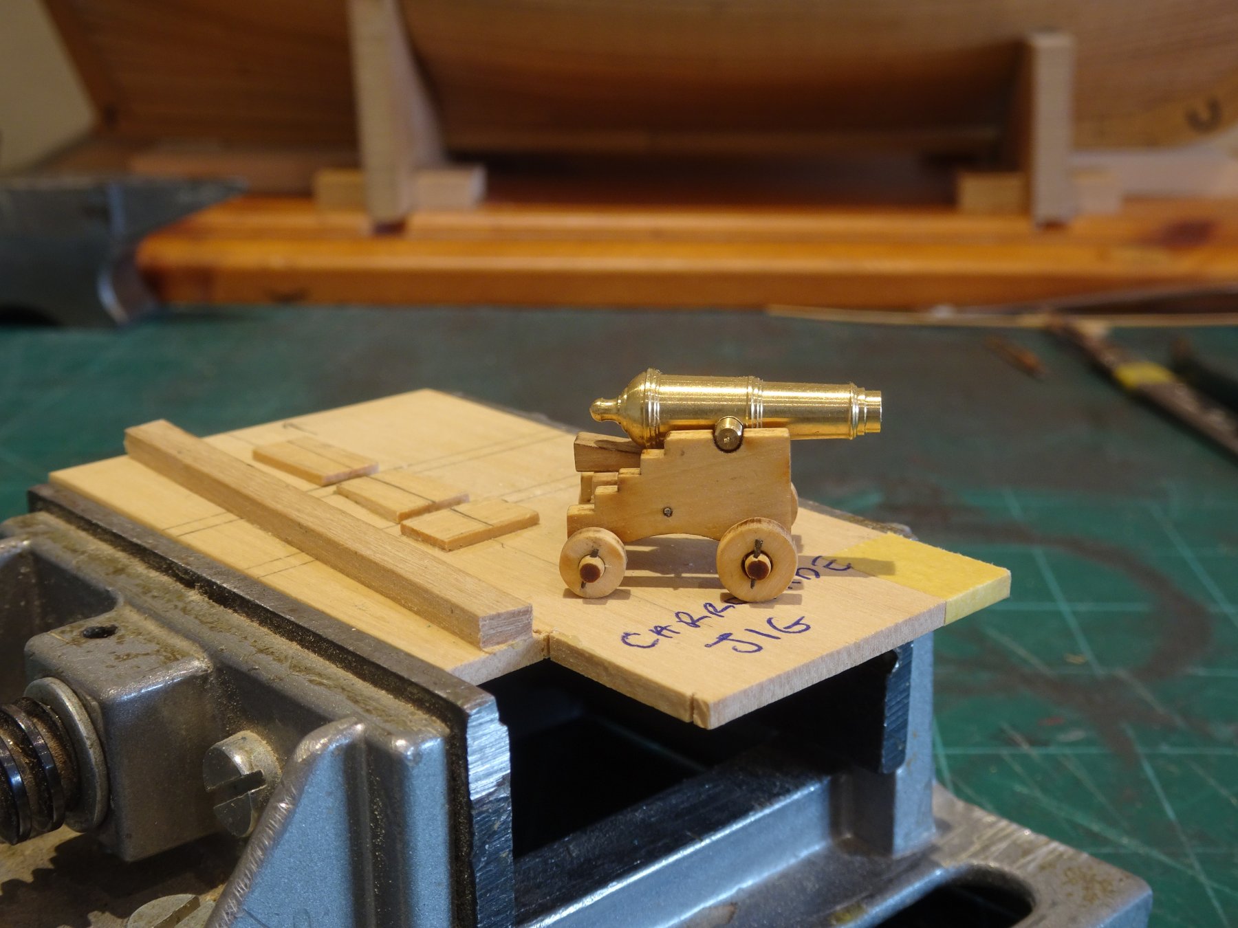
Post 48 A test Carronade I am assembling one Carronade at this stage to use as a test item for Gunport fit etc; and develop my assembly technique. Cheerful was armed with ten 12 pounder carronades and two 4 pounder long guns. The carronades as supplied for the kit have a somewhat unusual appearance sitting on carriages with trucks, and with trunnions to secure the barrels. This is at a time when slide beds were more common for Carronades, fitted with iron retaining hoops below the barrel, and Breeching rings above the cascable. There were however many variations to how these guns were configured, and Chuck's carronades which are a thing of beauty, will do very nicely. 4313a This arrangement from the NMM is very close to Chuck's version, but with the addition of the Breeching Ring atop the cascable. I think a simple jig is essential for this process, in fact assembly jigs in general are an excellent idea, I used many such devices on my Pegasus build. 4313 Even with a jig these are tricky little things to set up right. I take the between axles measurements from the plan and transfer to the jig. Small strips of scrap Boxwood secure the axles in place, and the finished item looks remarkably like Chuck's little jig. 4325 The axles are rounded at each end to take the Trucks before fitting in the jig for the attachment of the transom on the front axle, and the Bolster on the rear axle. 4322 One point to note is that the Transom above the front axle is not vertical but should lean back slightly. 4316 I used some 0.7mm ø wire, chemically blackened to represent the iron connecting bar which ties the side brackets and supports the carriage bed. 4331 I added Truck keys using 0.4mmø brass tubing flattened at one end to retain the trucks on their axles. These were then chemically blackened after trimming. 0.45mm ø holes were drilled thro' the axles to take the key. I will finish this off at some point but for the present it will suffice, and I need to concentrate on the decking next. B.E 05/11/2018

- 574 replies
-
- 19
-
-
- cheerful
- Syren Ship Model Company
- (and 1 more)
-
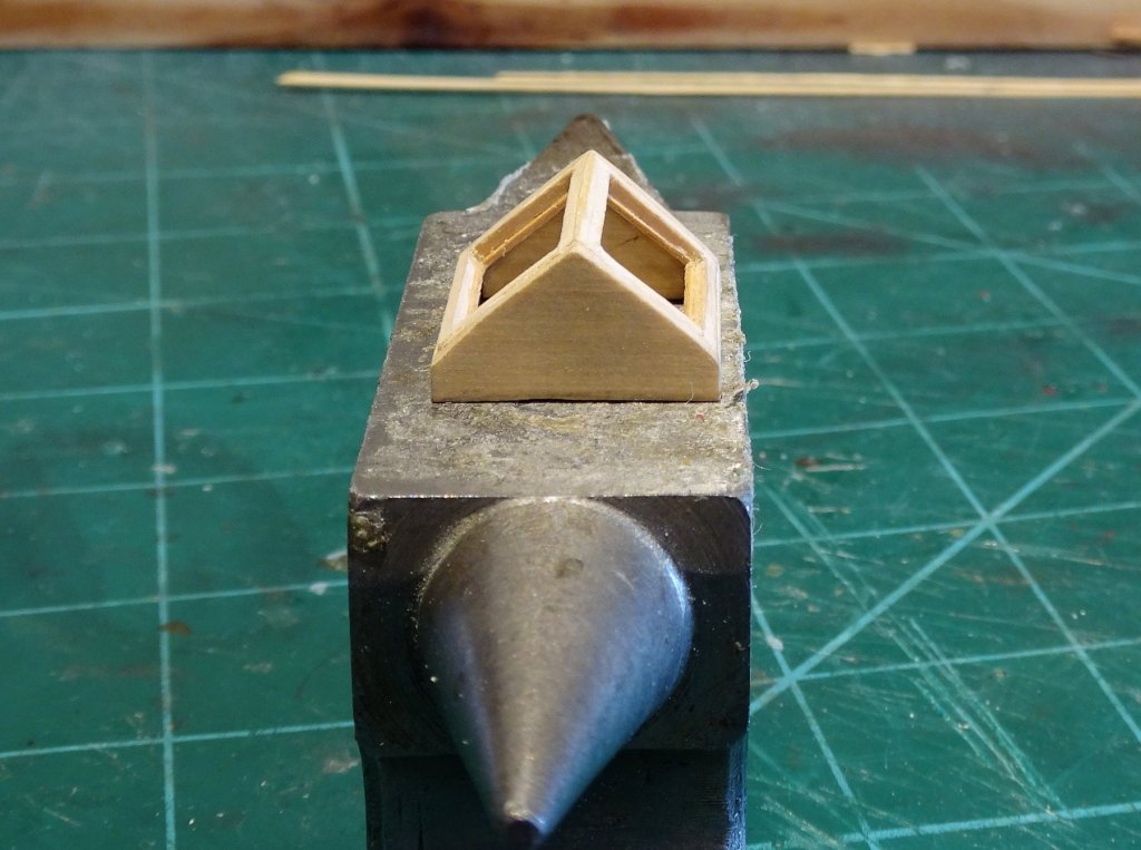
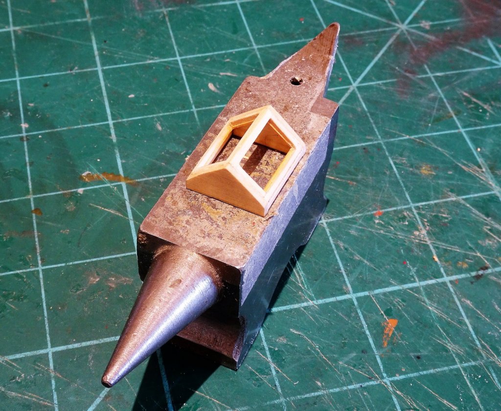
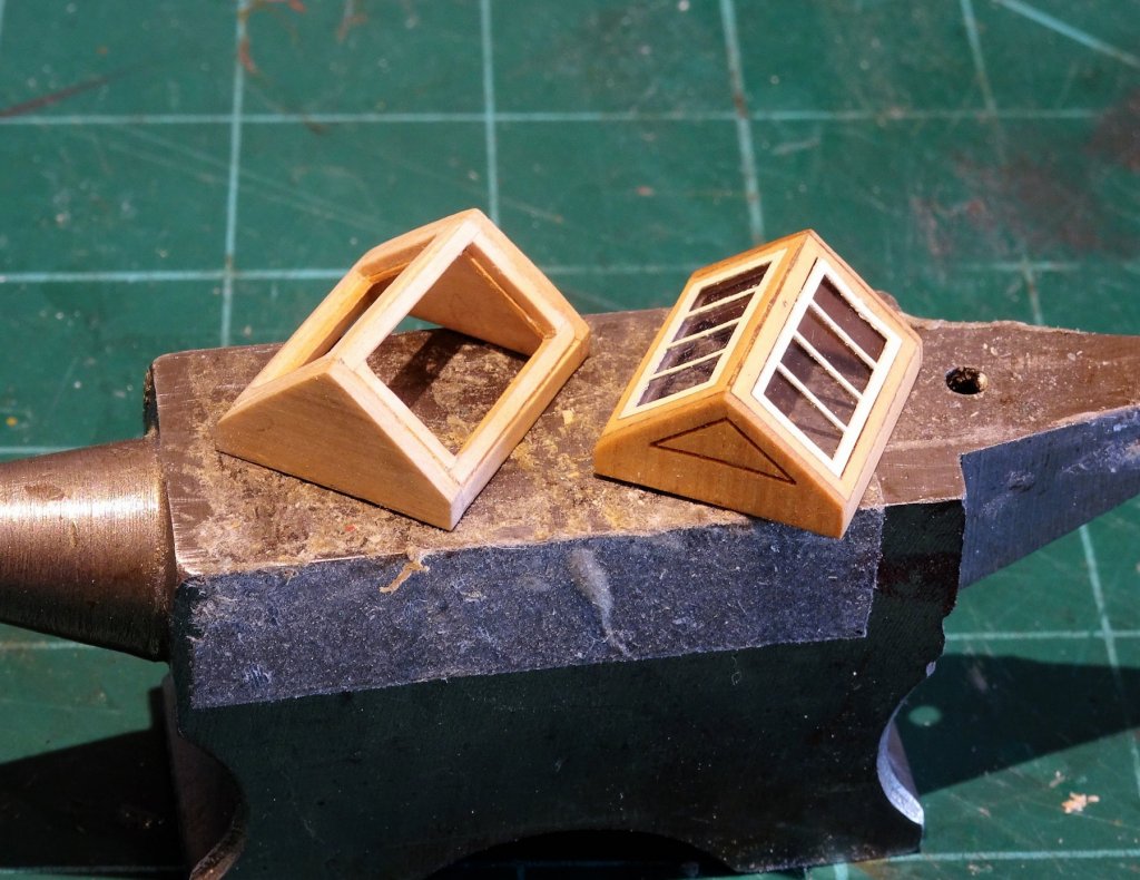
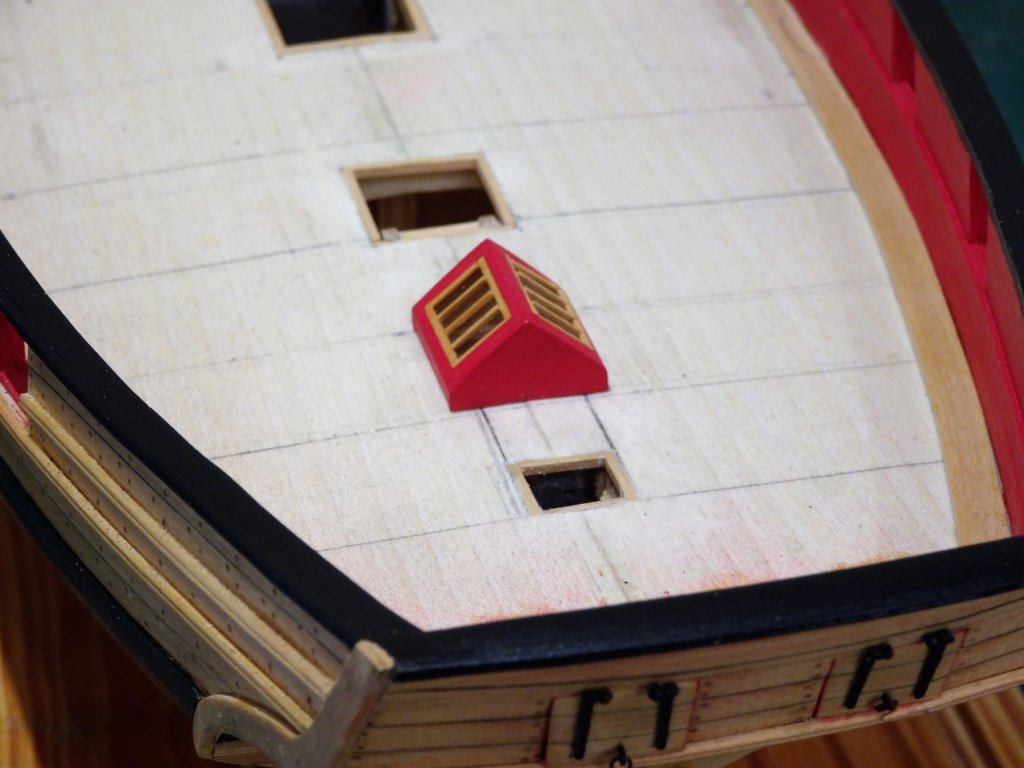
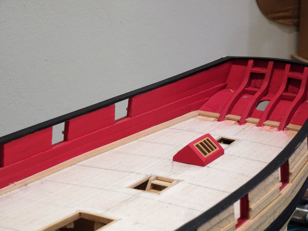
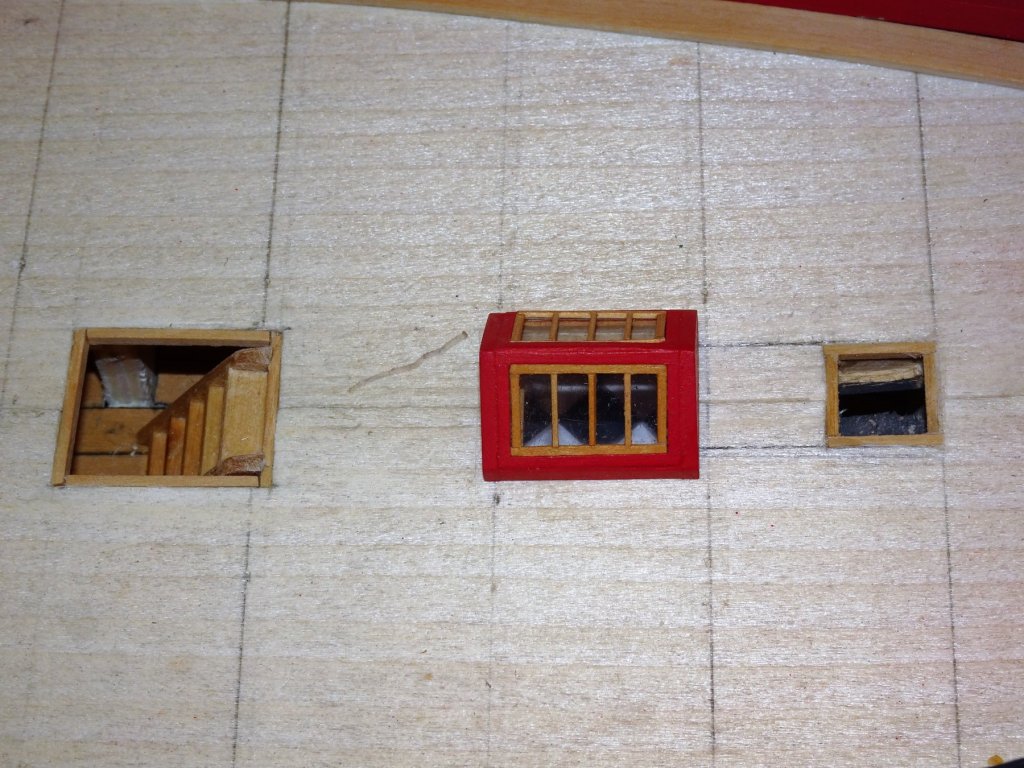
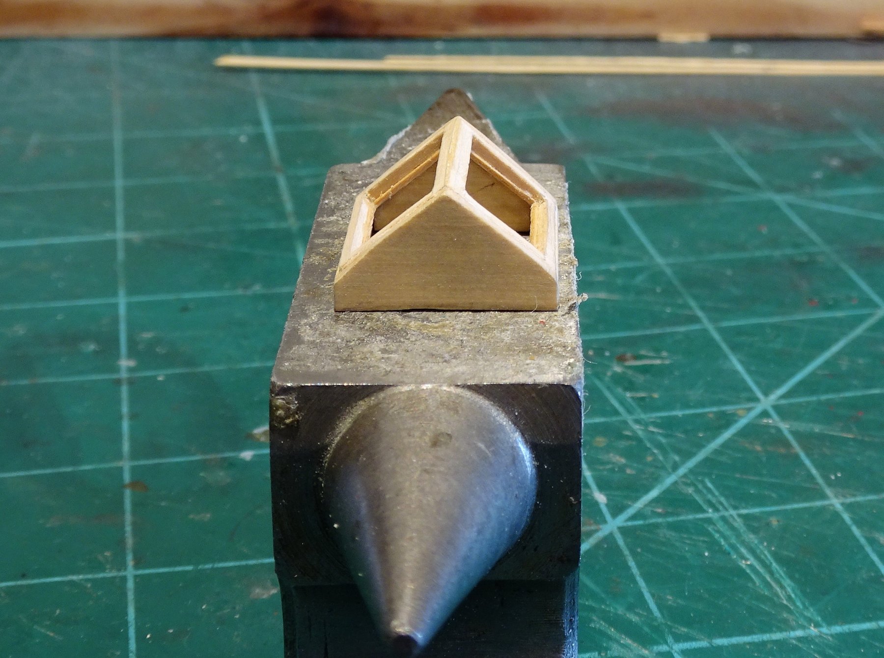
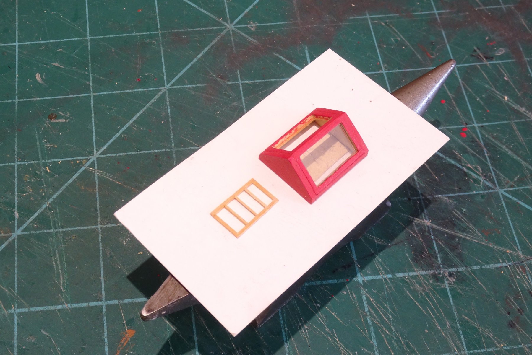
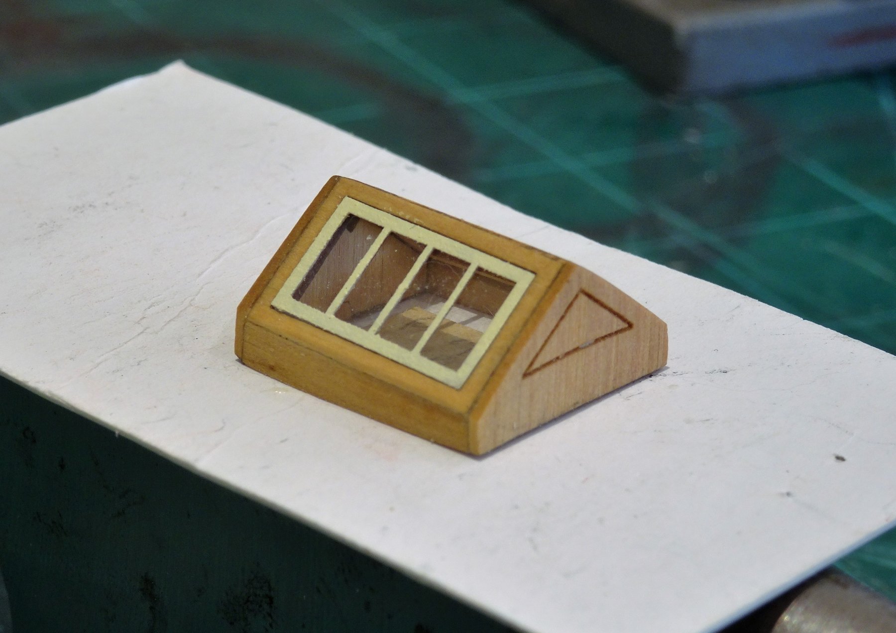
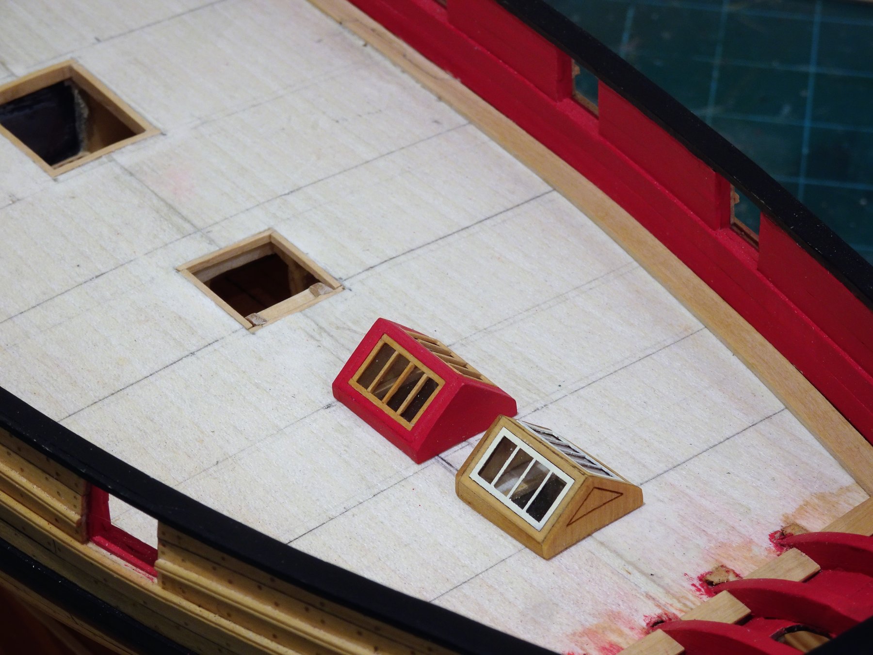
Thank you Thomas, Martin, and Paul. 🙂 Post 47 Faffing with fittings part 3. The final deck fitting in this section is the Skylight. I have Chuck's little mini kit which I assembled . The version with the coaming around it doesn't appeal to me, something to do with proportion of the coamings in relation to the skylight I think. 4268 I seem to be in a constant state of indecision whether to paint or varnish the inboard fittings but I eventually decided to varnish the kit Skylight with the window frames painted using Admiralty Paints Light Ivory. I comforted myself with the thought that I can always arrange for another little skylight to wing its way across the pond if I don't like it. While waiting for a further timber supply to complete the margin planks I carried on and made a scratch version from Boxwood sheet. 4204 4201 The frame completed. 4265 I decided to paint this one red but leave the lights framing natural. 4207 There wasn't that much extra effort involved in scratching the Skylight compared to assembling the delicate little kit. 4278 4279 4285 The deck covering below the Skylight shows sufficiently to make the effort worthwhile. 4282 To my eye the scratch version has slightly more 'presence' on the deck compared to the kit version, sweet as it is, and no doubt true to scale. B.E. 02/11/2018


- 574 replies
-
- 19
-
-
- cheerful
- Syren Ship Model Company
- (and 1 more)
-
I just love everything about your model Thomas. B.E.
-
Those close-up shots so clearly show the purity of your work Jason, beautiful finish. B.E.
-
Thank you Nils, Jason, and Dave 🙂 @ Jason - My inclination is to leave the deck fittings natural, I rather like the look Bob achieved on his Cheerful build, but we shall see once the deck is down. @ Dave - Good result with your gratings Dave, always a tricky business cutting into gratings they are so delicate. Fortunately my gratings are not glued to the coamings so I will be able to remove them for 'surgery'. Now I've established a working hinge method I think I could improve on it, but it will involve getting my silver soldering kit out - a little exercise for a wet afternoon perhaps. Regards, B.E.
- 574 replies
-
- 3
-
-
- cheerful
- Syren Ship Model Company
- (and 1 more)
-
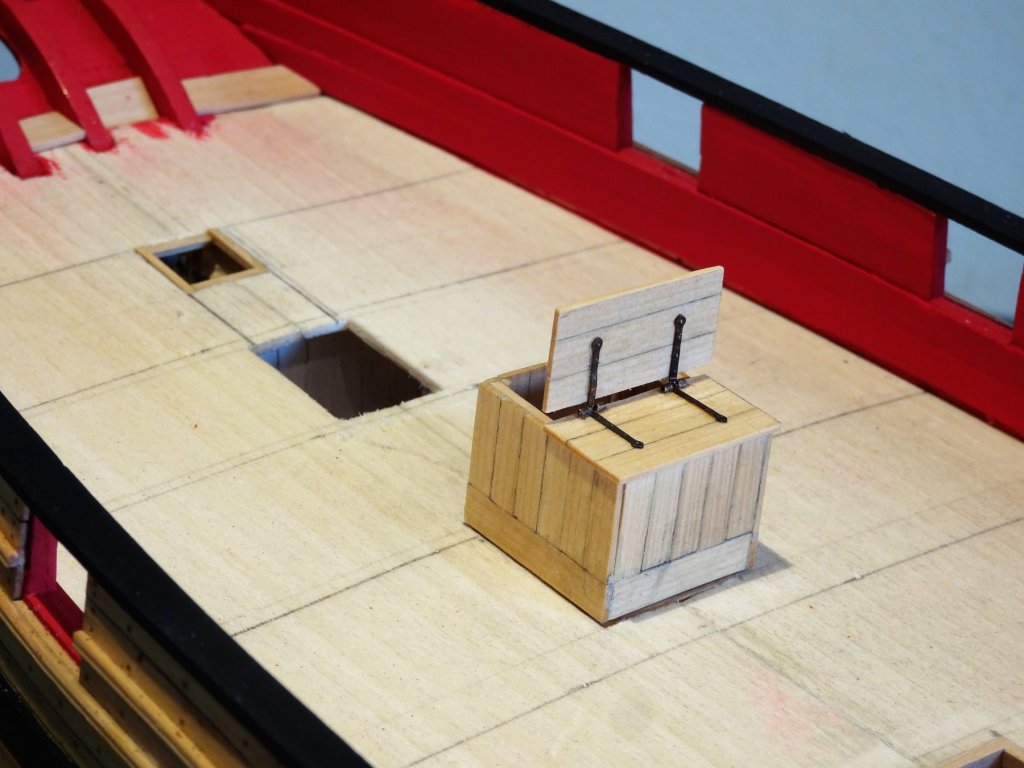
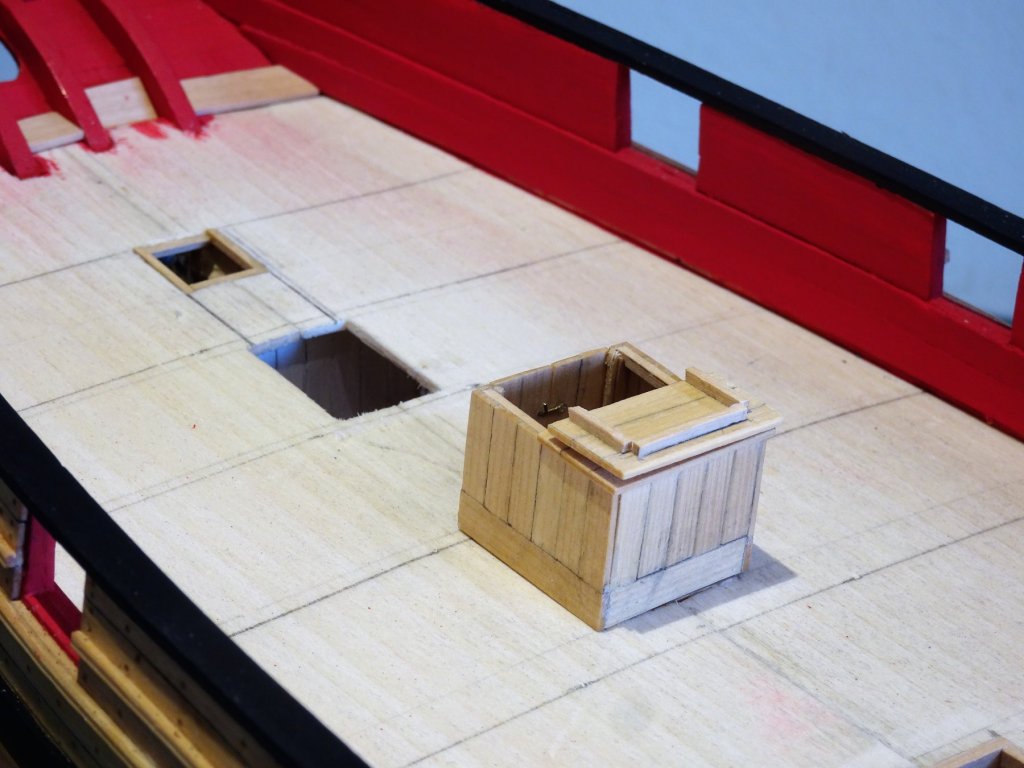
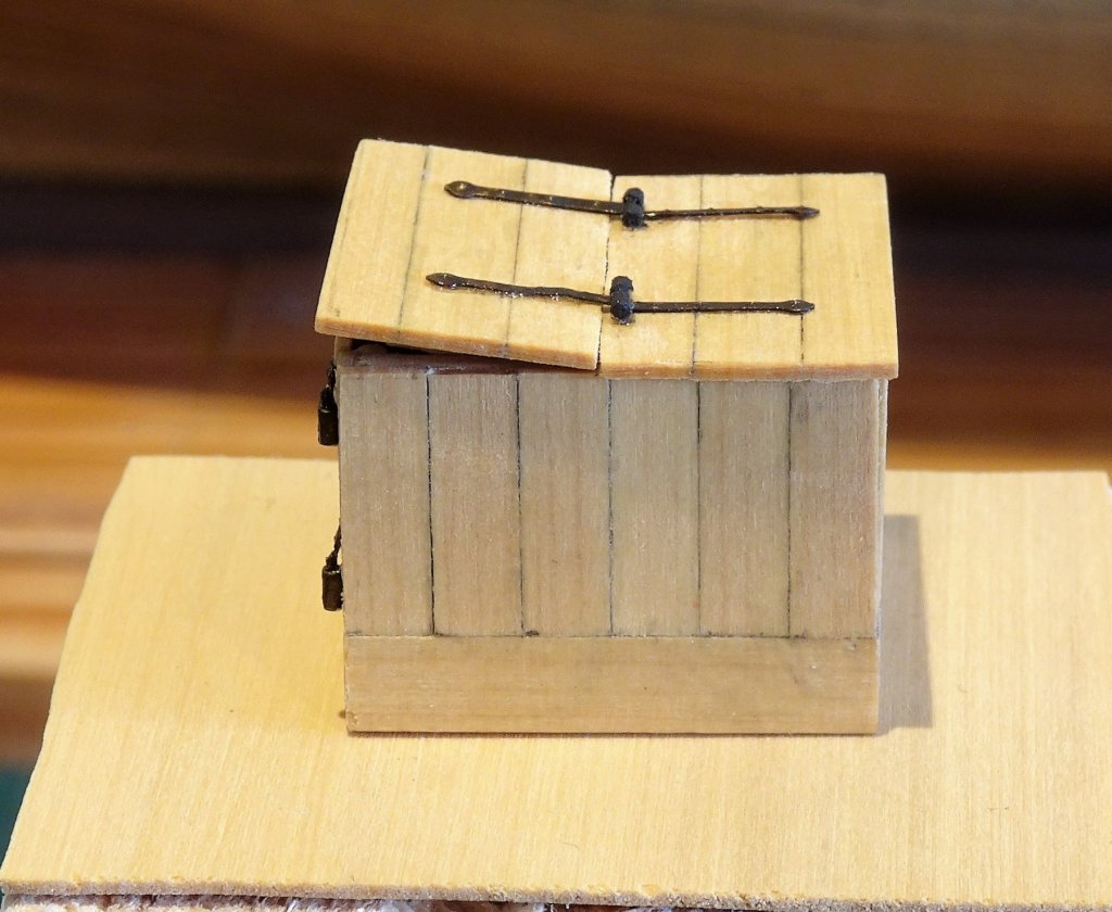
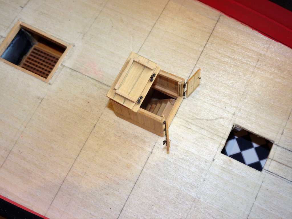
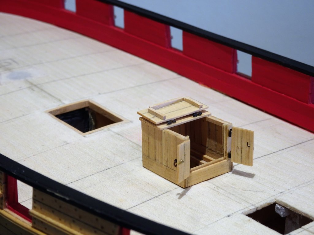
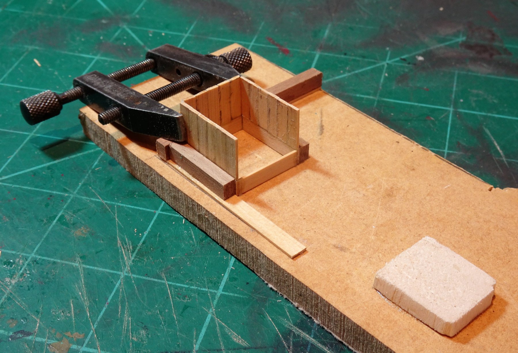
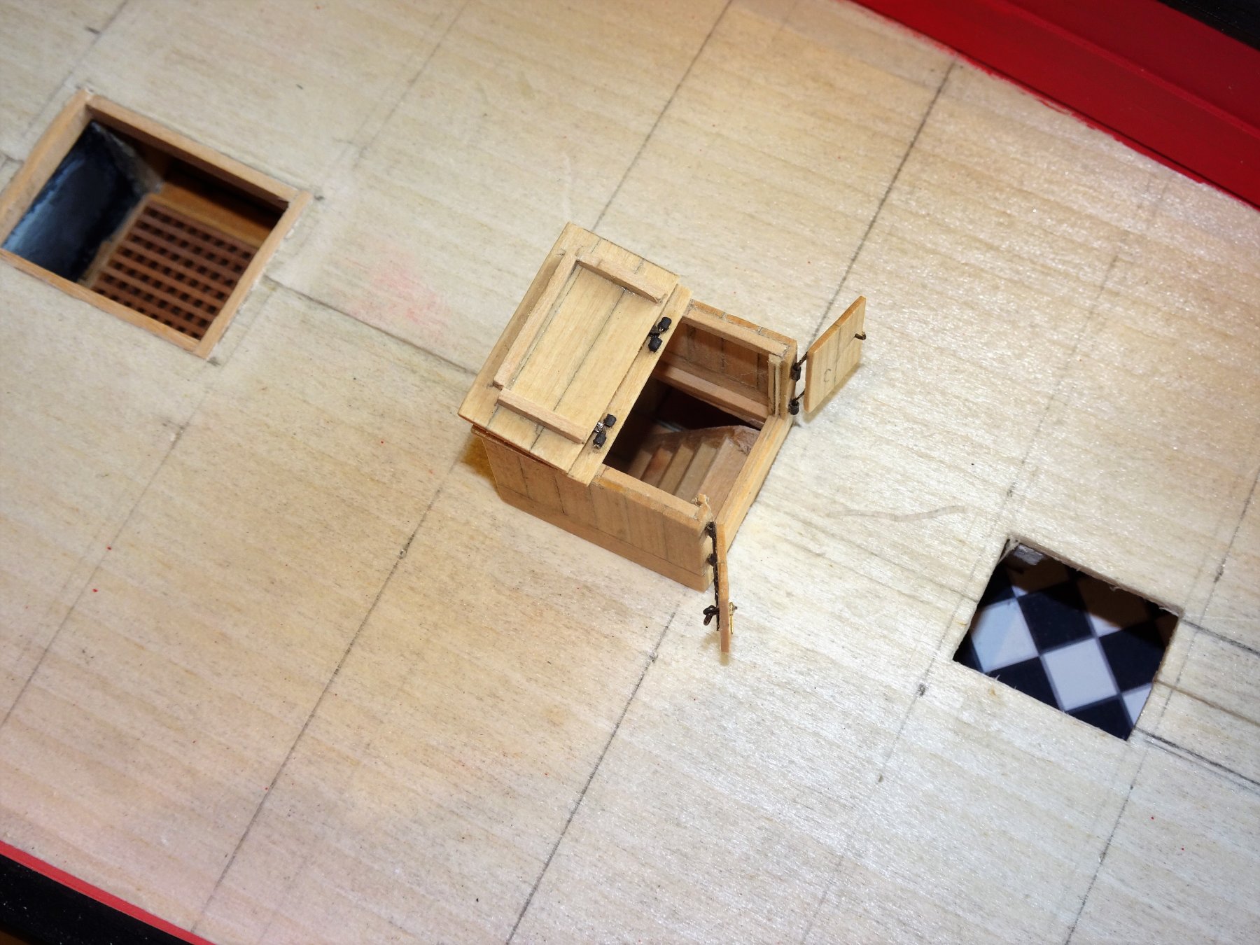
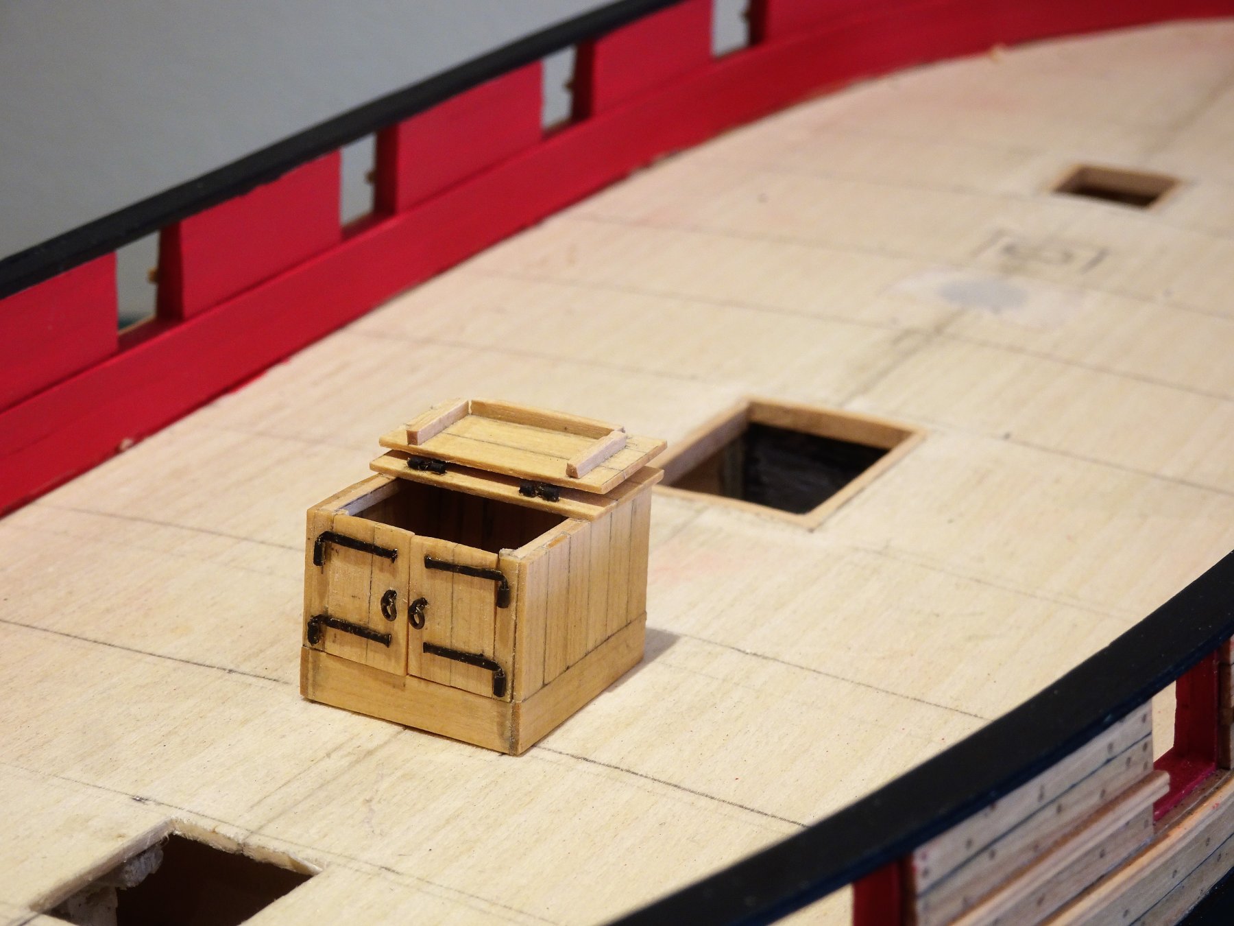
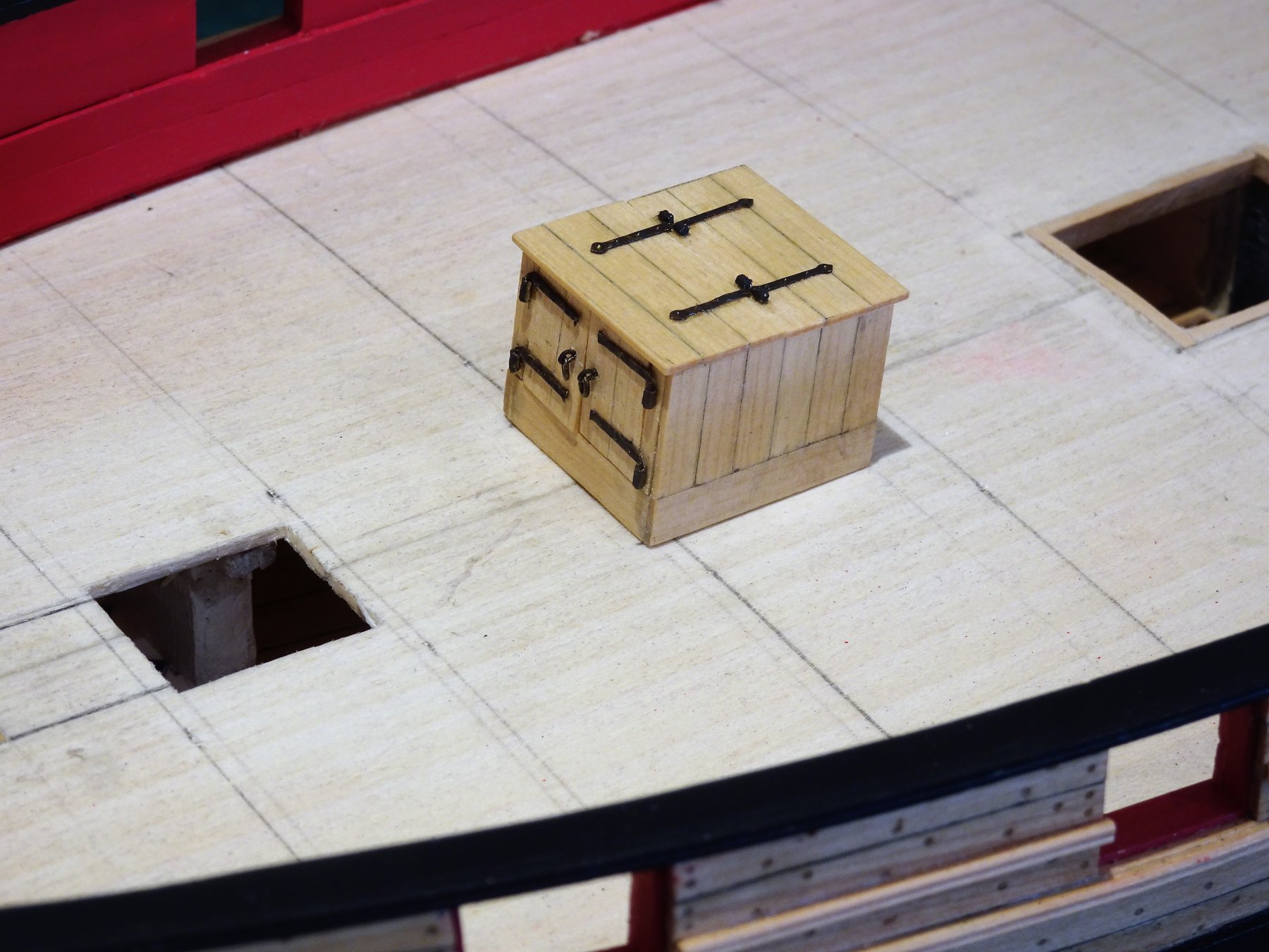
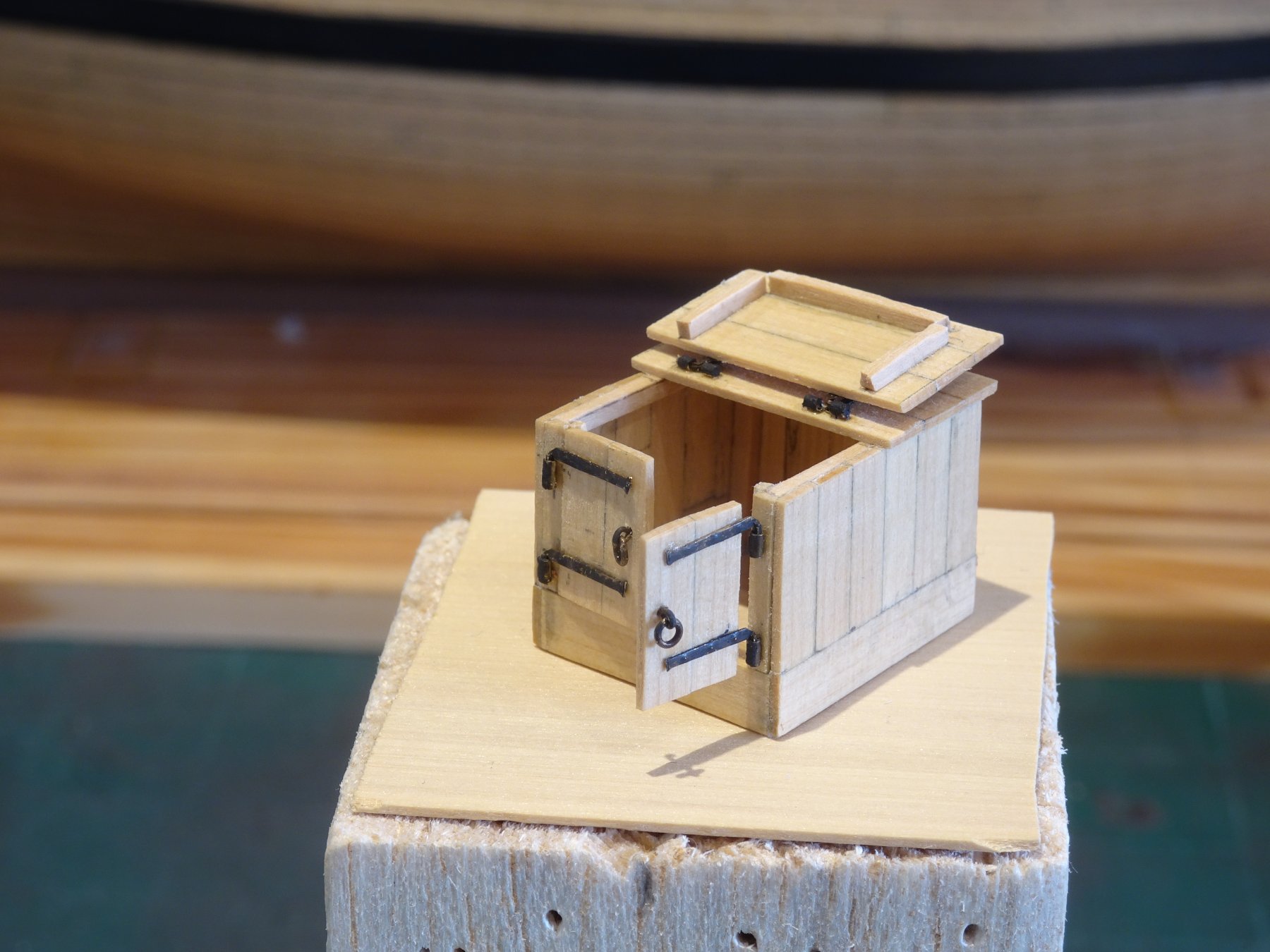
Post 46 Faffing with fittings part 2. I now turn my attention to the Companionway. This is an interesting little project particularly when choosing to try and make the doors open and the lid hinge back to reveal something of the interior. 3588 A jig was necessary to keep the sections square and in place during gluing. For construction I used 1/32" x 3/16" strips for the boarding, and 5/32" strips for the coamings. 3725 Internal framing was added to stiffen the construction. The rear half of the lid was glued in place and the forward half hinged to fold back. 3727 It proved a testy business to make tiny hinges that would both work and have at least a nod towards looking like the real thing. Of course all of this makes not one jot of real difference to the model, but I derive a small personal pleasure from it, even if just knowing it's there. ☺️ 3743 Completing the arrangement also required a ladder down to the lower deck. 3705 3706 3758 Mildly curious why the access doors are facing aft, most of the examples I've seen they are either facing forward or to Starboard. 3751 3752 I haven't made my mind up yet whether to paint or poly wipe so for the present I will leave it in its bare wood state. Either way it will need some final finishing before gluing into place. Onto the Skylight. B.E. 17/10/2018


- 574 replies
-
- 21
-
-
- cheerful
- Syren Ship Model Company
- (and 1 more)
-
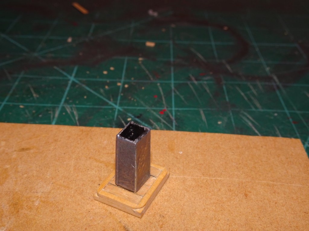
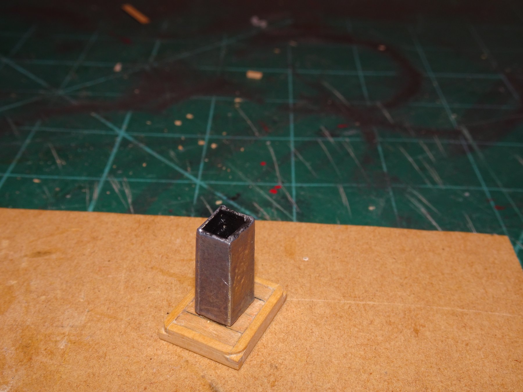
Hi Martin, the answer is neither.☺️ The Flue was constructed using 0.6mm Boxwood strip, edge glued, and then covered with a very fine 0.1mm 'Lead' foil to represent a metal finish. I would have otherwise used thin brass, chemically blackened, but this method saved me some fiddly silver soldering. Thanks Dave, this feature is indeed shown on the contemporary cutter models and plans shown in The Naval Cutter Alert book by Peter Goodwin. I will include the cut outs on my model as I like to rig the anchor cables along the deck. Regards, B.E.
- 574 replies
-
- 3
-
-
- cheerful
- Syren Ship Model Company
- (and 1 more)
-
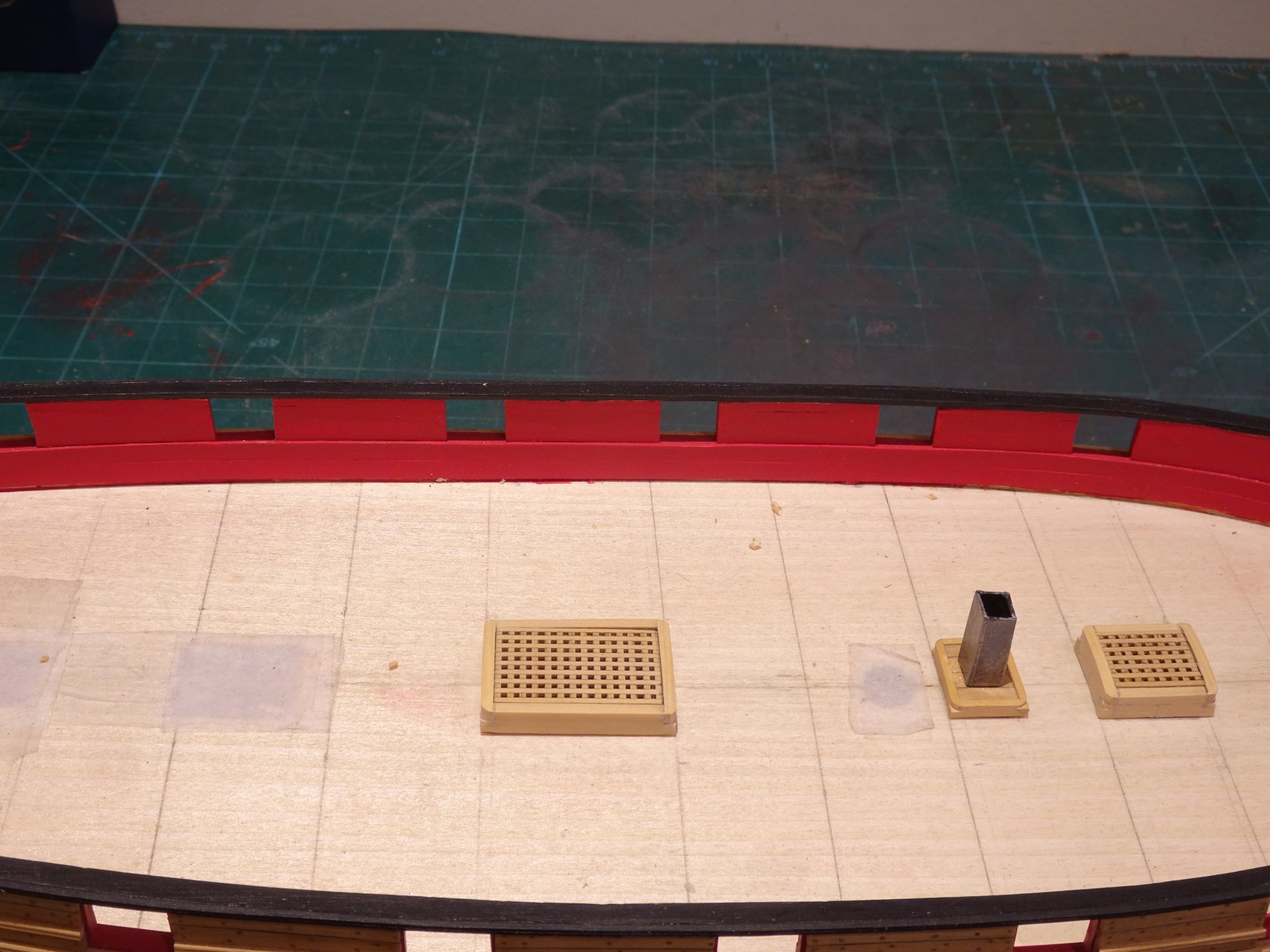
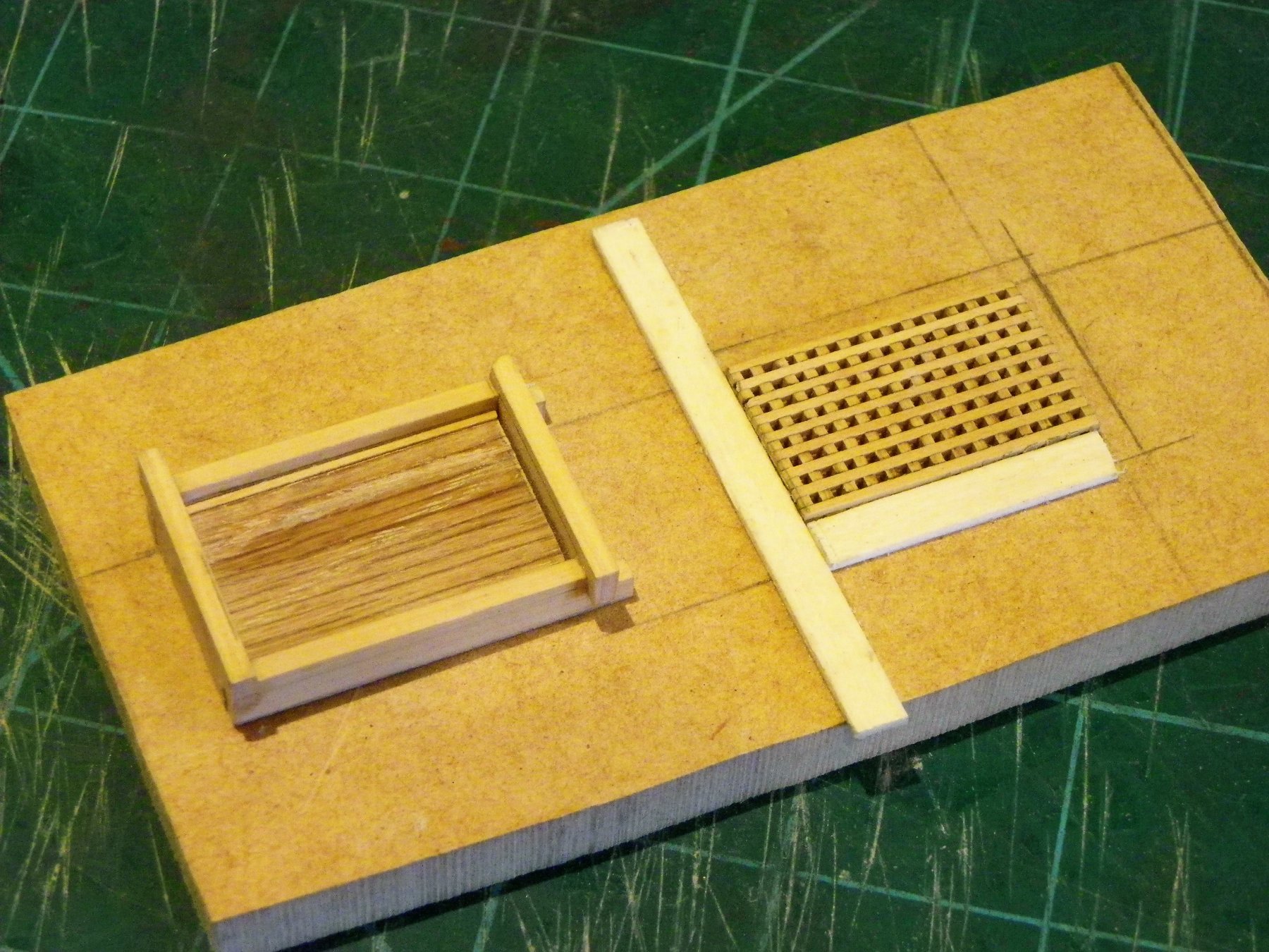
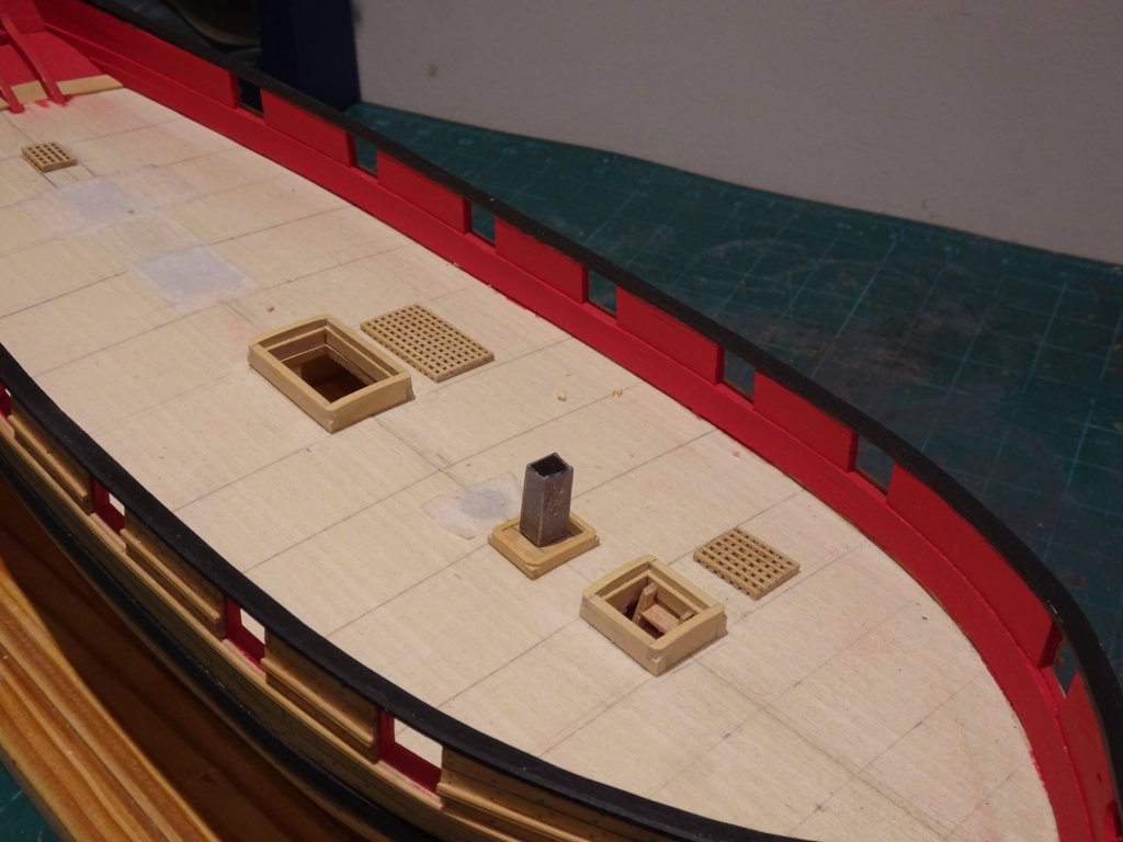
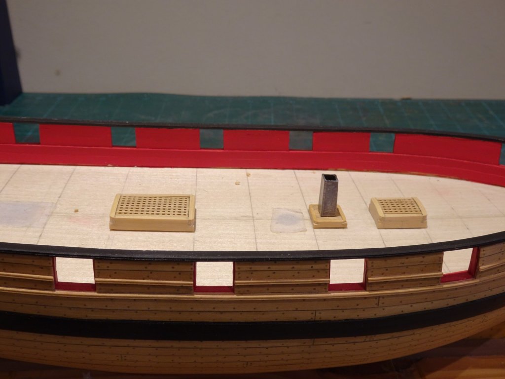
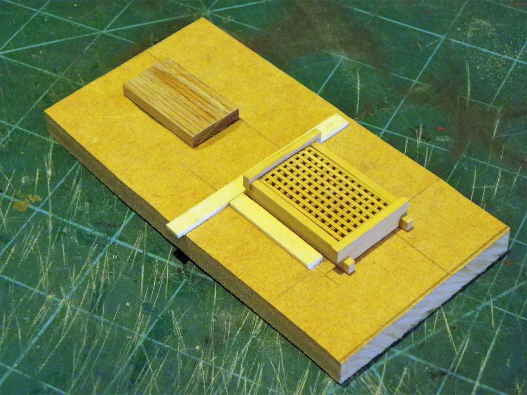
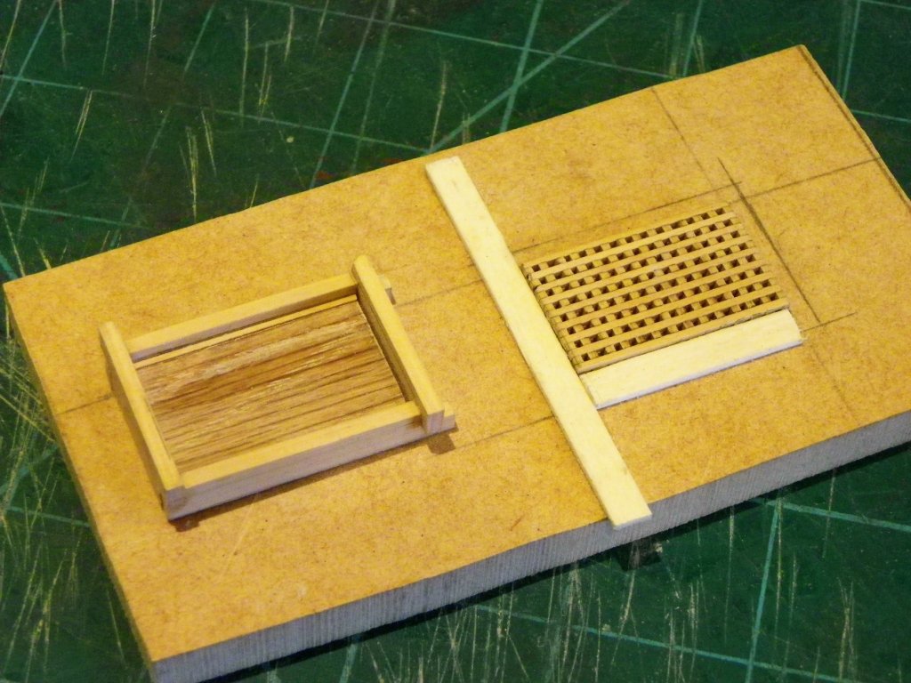
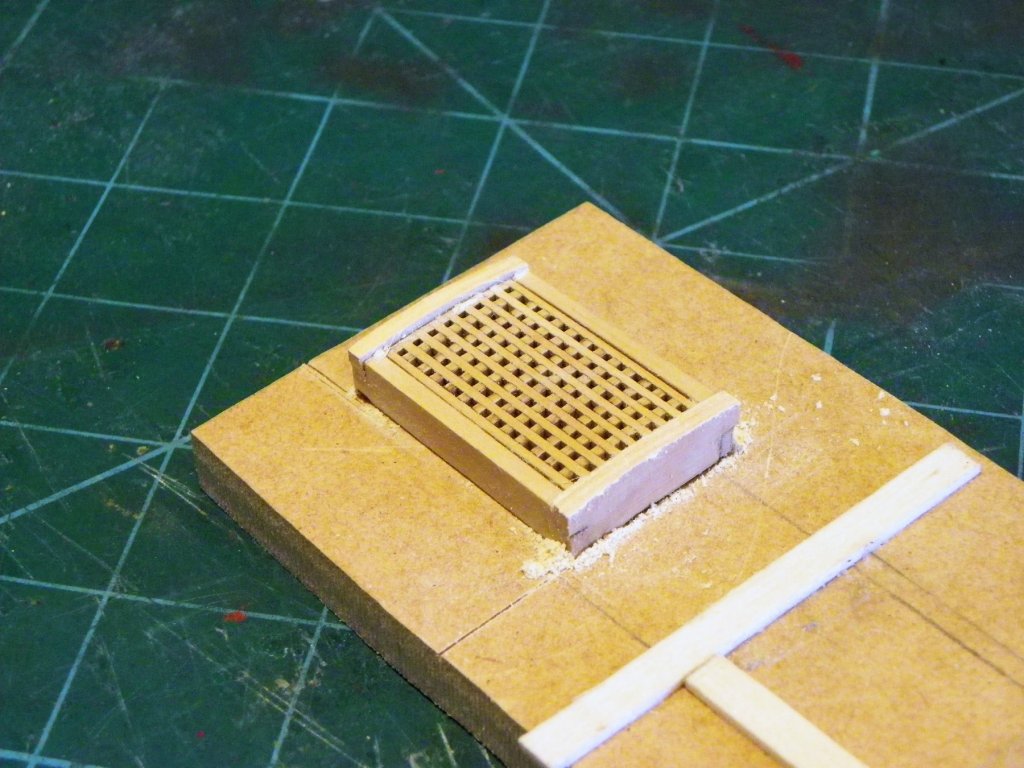
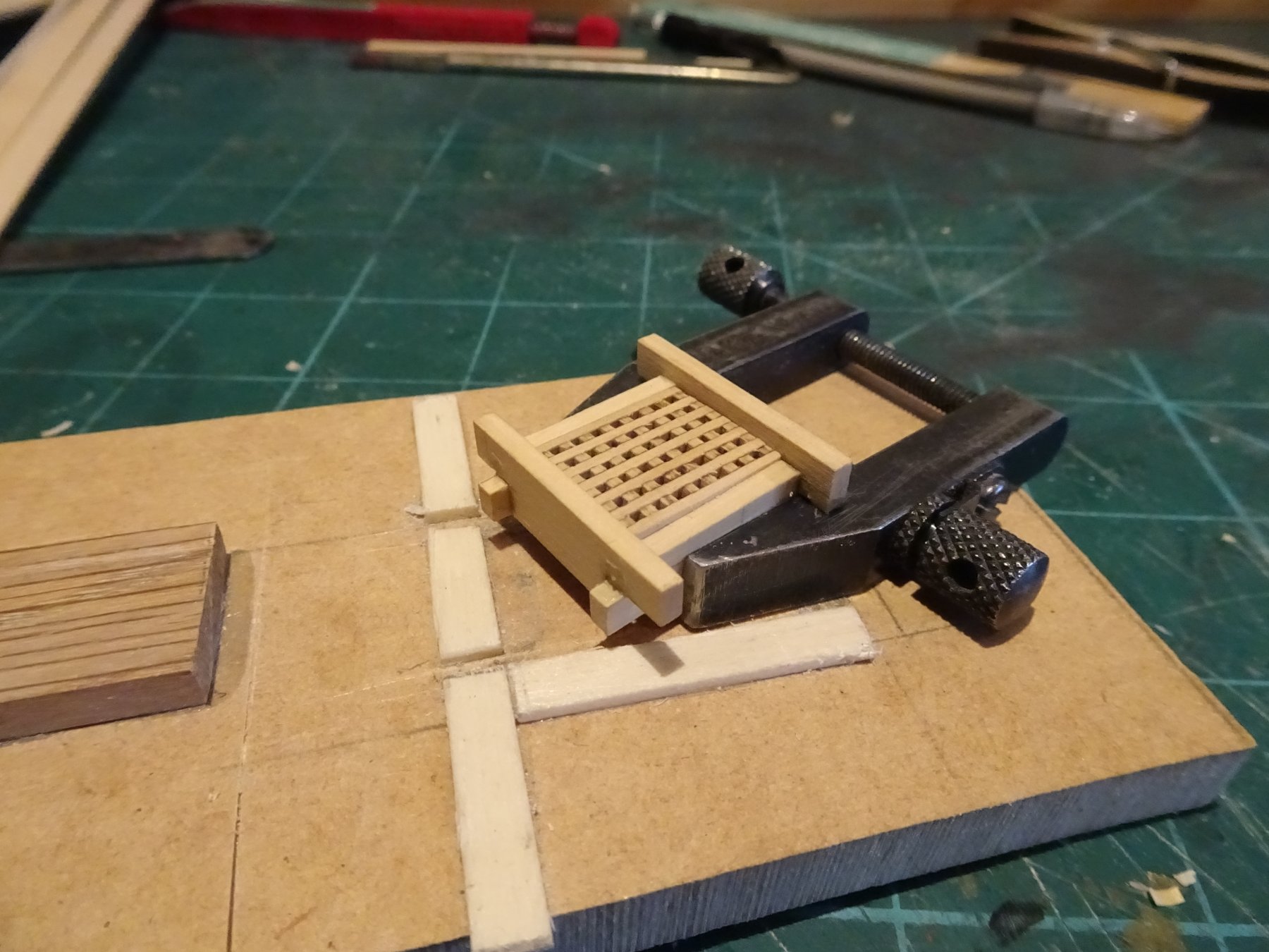
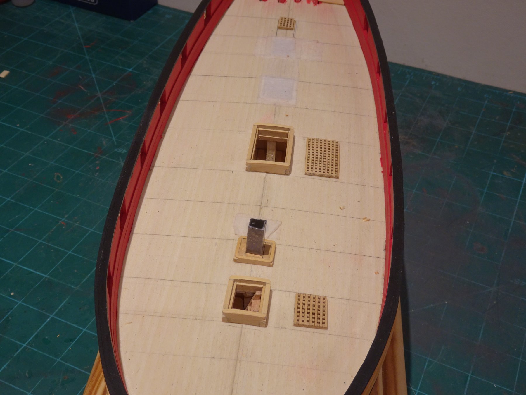
Cheers Guys for the 'likes' and comments. Post 45 Faffing with fittings. A while ago I decided that the Holly decking planks I had originally ordered were just too pale for my taste, so I ordered replacement Boxwood strips. Pity I forgot to include a sheet of 3/64 thick stuff in the order to cut out the bow area of the Margin planks. I have put a further supplementary order for some 3/64" Boxwood sheet and strip, but in the meantime I will have a go at the gratings. Chuck's little gratings kits work a treat, and result in a nicely curved fine grating that reflects the shape of the originals. Starting with the Bread Room scuttle I continued to complete the set of three. Gratings are one thing, the coamings and head ledges entirely another. These are scratch built from 3/32" sheet. The only size reference for the height of the coamings is on the plan I worked on a 6mm depth from the false deck. The Head ledges I made slightly higher to allow for forming the round. 4436 As suggested by Chuck I formed the frame around the grating to get a good fit. Once formed I inserted 1/16" strip around the inside to support the grating. This also has the effect of stiffening up the fame and reduces the risk of pulling it out of square. 4437 Even so during final finishing I glued a grating sized block to my jig board to hold the framing in place. 4446 Sanding the Head Ledges. 3584(2) The finished coamings sit 5mm above the false deck. 3554 Same procedure for the Fore Hatch. Galley Flue scuttle I cut the base from some 3/32" Castello sheet. From the plans I calculated a base 12 x 16mm. For the coamings I cut a 3.5mm width strip from a 1/16th thick sheet. I cut the hole for the flue out and boarded around it with some thin Boxwood planking. 3571 The Flue pipe was then added. 3579 3580 3584 3585 Next up the Companionway and the Skylight. B.E. 13/10/2018 ps. Thank you Chuck, received my 3/64" Boxwood sheet, and 1/4" wide strips for the margin planks this morning, - six days order to door, excellent service.👍


.thumb.JPG.cbb814e5a177d7e7041b204cbcdcd778.JPG)

- 574 replies
-
- 15
-
-
- cheerful
- Syren Ship Model Company
- (and 1 more)
-
I so admire those who can create carvings, but my attempts on Pegasus ended in abject failure. The figures are so small and I simply couldn’t get down to size using either wood or fimo. By any stretch of imagination what resulted hardly represented classical figures of Greek mythology. I was saved by a Preiser set of 1:87 scale ‘Adam and Eve’ figures which I was able to convert into passable representations of Perseus(complete with Medusa’s head,) the Princess Andromeda, and Athena and Poseidon, all associated with the Gorgon legend. The decoration is of course all conjecture and even the decoration shown on the Admiralty plans is probably just artistic licence, I doubt the Navy Board would sanction such expense for a humble sixth rate. Still I look forward to admiring the work of those with more resolve than me.😊 B. E.
- 467 replies
-
- 1
-
-
- fly
- victory models
- (and 1 more)


.JPG.c013ad3967a5ff25a5576ea1eac1e356.JPG)


.JPG.5e89ee3e1ebd5be1d50f55dd2258c7c7.JPG)