
.JPG.ca33079f5815b861e67b9c2cccd37982.JPG)

Blue Ensign
-
Posts
4,571 -
Joined
-
Last visited
Content Type
Profiles
Forums
Gallery
Events
Everything posted by Blue Ensign
-
 Michael , You could try thinning your wipe on with a little white spirit, I make my own by diluting oil based polyurethane by 50% B.E.
- 90 replies
-
- 2
-

-
- english pinnace
- Finished
- (and 1 more)
-
A fine build in the making, very nice hull work Peter 👍 Cheers, B.E.
- 236 replies
-
- 1
-
-
- artesania latina
- kitbashing
- (and 2 more)
-
Your rigging is a work of art Kirill, I love your use of both taut and slack lines which adds so much realism, and getting those crows feet to look so good is a mark of your skill. This is a beautiful model and much to be admired. Regards, B.E.
- 228 replies
-
- 2
-
-
- spanish galleon
- lee
- (and 1 more)
-
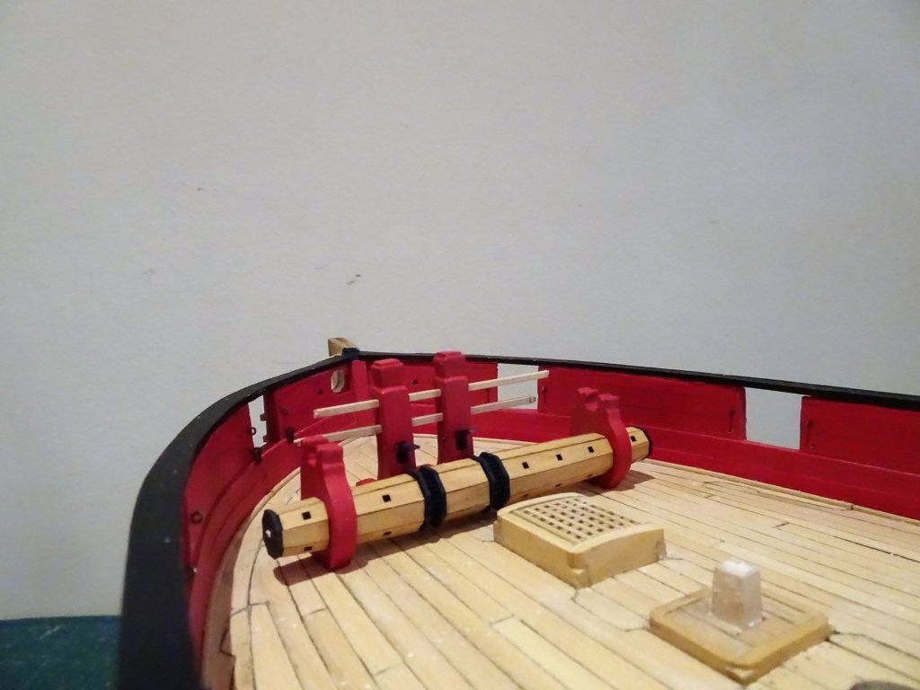
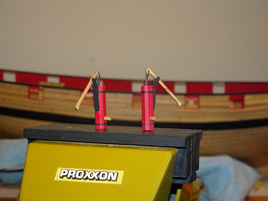
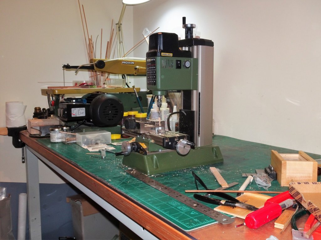
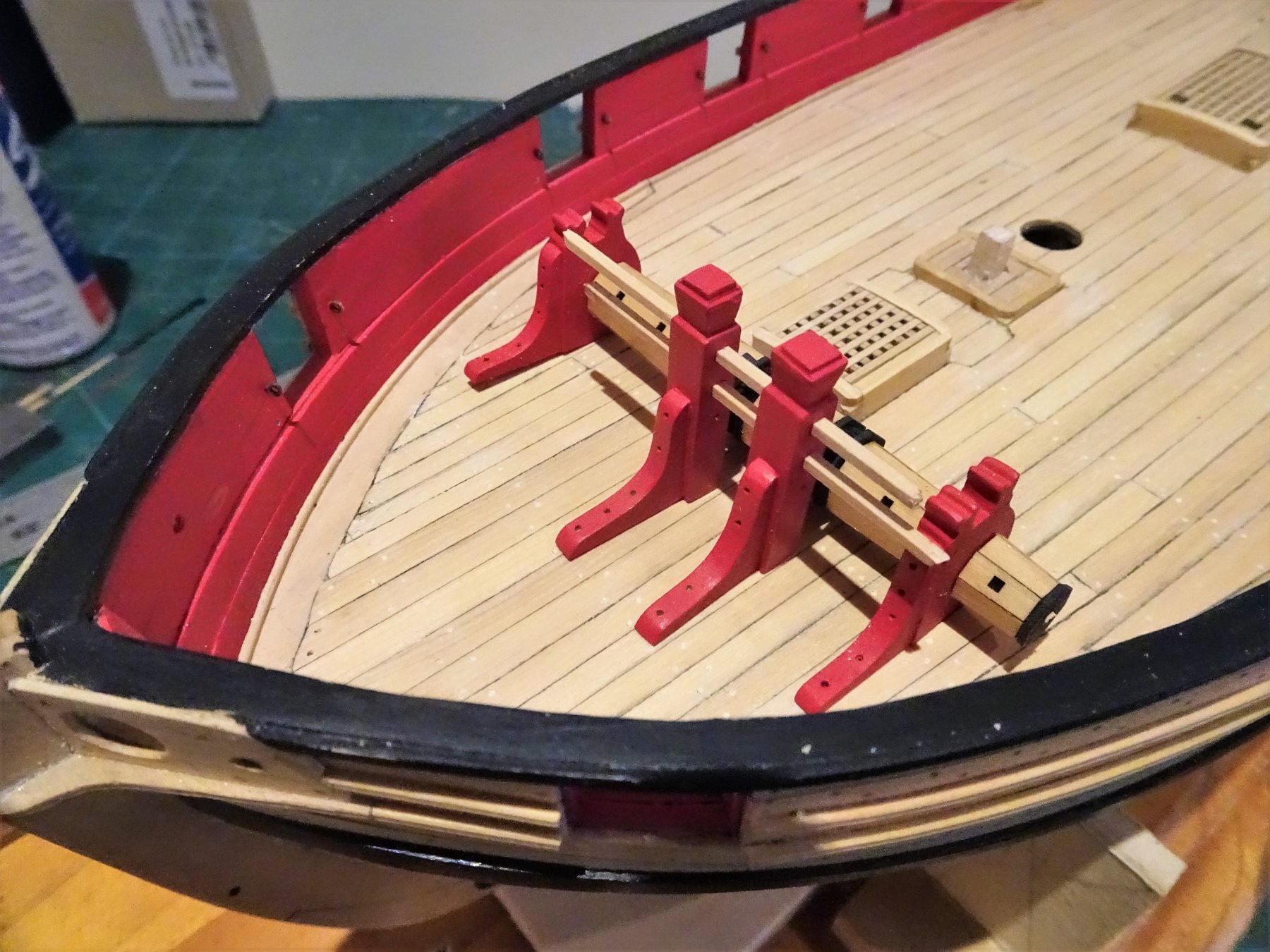
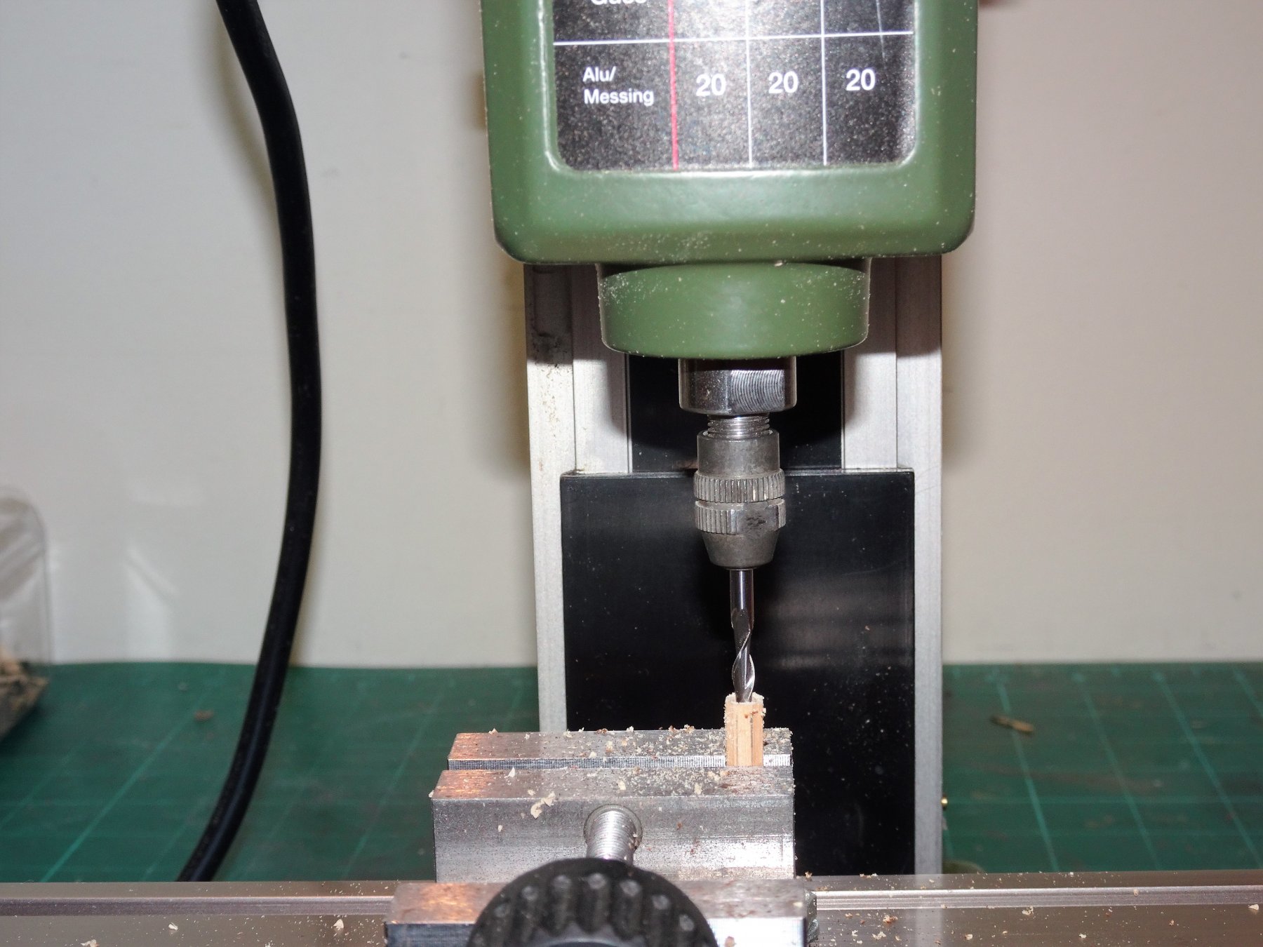
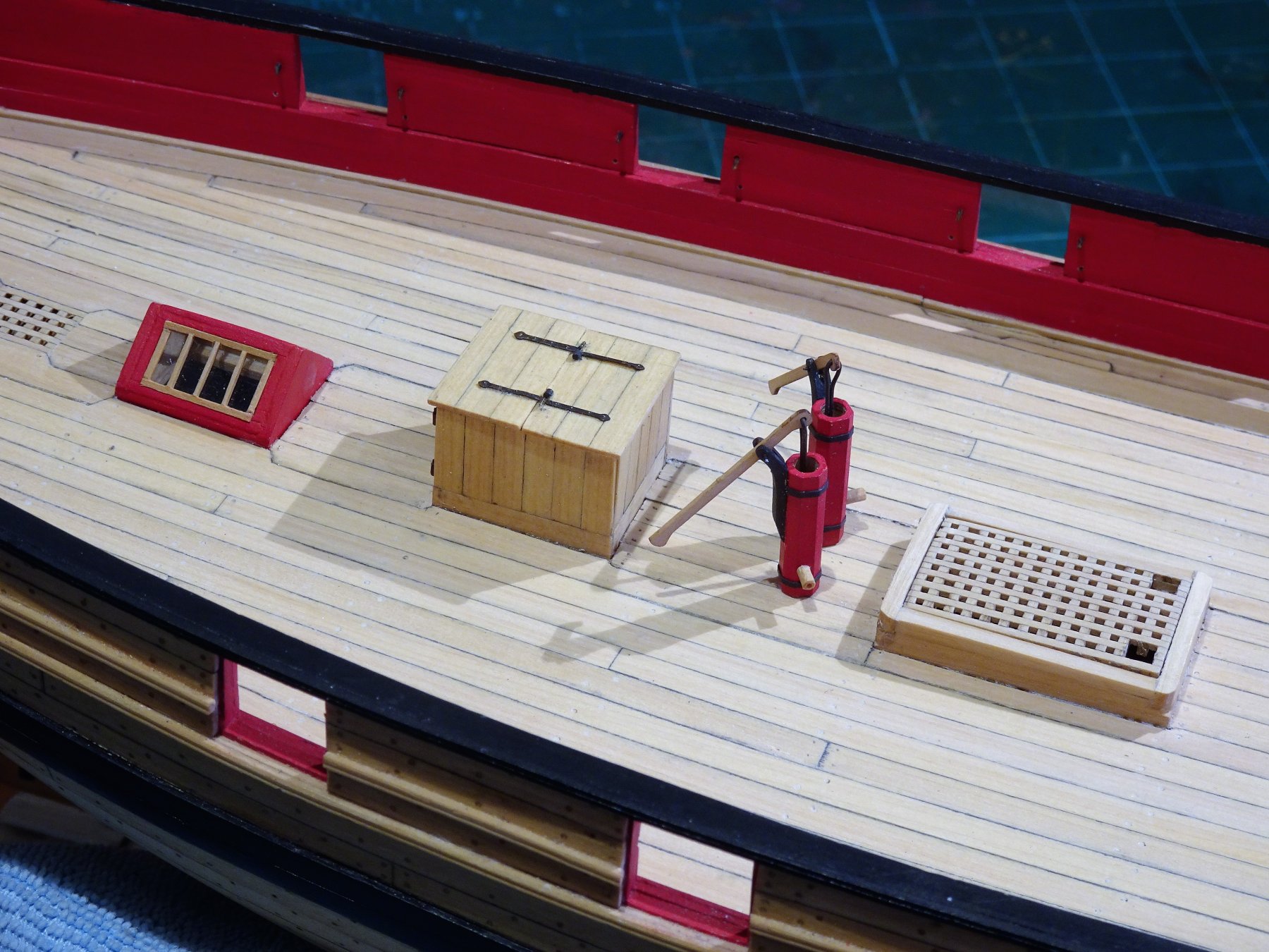
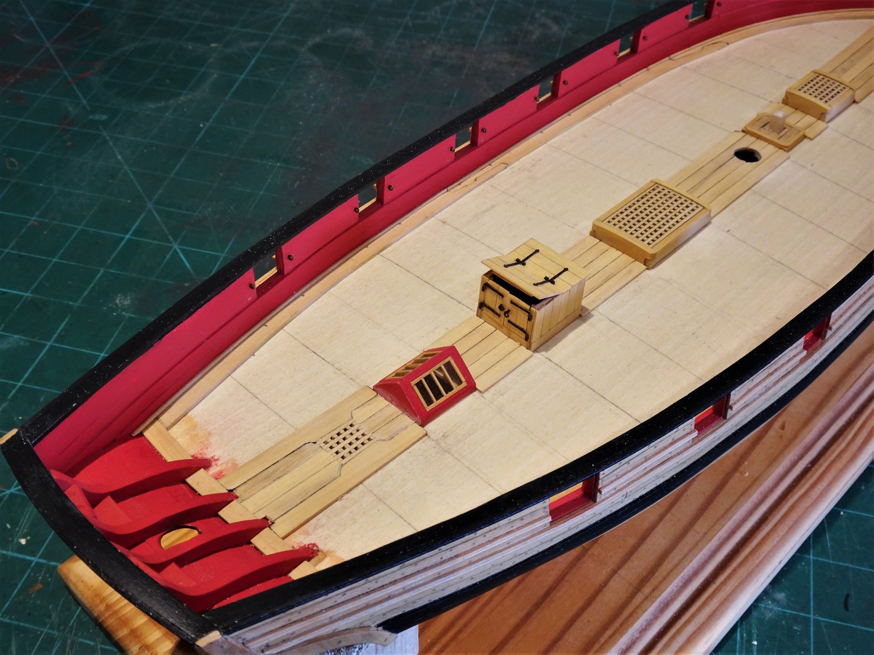
Post 56 Inboard Fittings With the deck laid there are areas requiring re-touching, and the treenails to be added. I pondered a little about doing the treenails, as I don't think Chuck added them. In the end I decided to add them. I mixed a fresh batch of filler tinted with a paler tone to fill the around 600 0.6mm holes. 4893 The deck is then re-scraped for a final time before sealing. I use 'Admiralty' brand Flat Matt Varnish. A water based varnish which I don't particularly like, but it does give an unvarnished look to the deck whilst at the same time sealing it. 4897 The treenails are barely visible, which is the effect I was after. 4899 With completion of the deck it's all about fittings from this point on. Windlass This is the most prominent and interesting deck fitting on Cheerful, and I am using Chuck's beautifully thought out mini-kit for the purpose. 4865 I have decided to leave the barrel of the windlass natural but paint the standards red. Associated with the windlass is the Bowsprit Step and pawls Bitt; these are assembled next. Again I have used a Chuck mini kit; it fits together with very little adjustment and very nice it is too. 4862 4863 Not completed at this point, these two items along with the Bowsprit will be considered together a little later in the build. Elm Tree Pumps Once again I avail myself of Chuck's little mini kit. The provided square stock for the body does need converting into the traditional octagonal shape, and for this I bring a little 'V' jig into use, last used on my Pegasus build. 4944 The body parts are only 20mm long so it helps to have a method of securing them whilst the octagons are formed. 4952 A busy day in the workshop, and Cheerful has to make way on the bench. The body does need drilling out and the centres were marked prior to shaping. 4948 The hollow centres were drilled out on my mill using a 3mm bit. A little bit of fettlin' of pump handle and brackets and they're ready to assemble. 4970 For the iron bands around the body I use slices of heat shrink tubing, a thing I favour for this type of feature. 4966 Undecided as yet whether to leave the Brake handles and discharge pipes natural. There is still the Winch to do but Shock, horror, 😲 I find there is no comforting little mini kit from Chuck which means I must shake myself out of complacency and do a bit of scratching. So this seems to be a good point to end the posts for 2018 and thank all my fellow builders for their interest, support, and help over the past twelve months. Merry Christmas and a Happy New Year from me and my stalwart Shipyard Assistant, William. B.E 21/12/2018


- 574 replies
-
- 25
-
-
- cheerful
- Syren Ship Model Company
- (and 1 more)
-
Coming along nicely Michael, 👍 B.E.
-
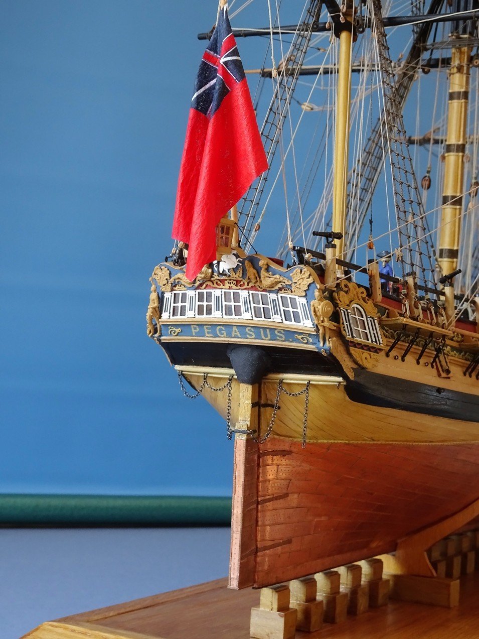
Thank you Wallace, I'm pleased the log is of help to you. Rudder coats would have been applied on any ship where the head passes thro' an internal deck, and because they can be tricky little beggars to fit, how to attach them to the counter needs to be considered at a stage where the model can be easily handled. This is the coat on my Pegasus build, not the prettiest of fittings but one that should be there. One other thing that may be of interest to you on this photo are the Pintle and Gudgeon straps. Note they are coloured to represent the cuprous alloy from which they were made. Iron over copper does not work, as our 18th c shipwrights found out. Cheers Dave, the rudder will be unshipped for later, I too have had accidents with rudders, once fitted I now use a small bulldog clip along the keel to hold them rigid whilst I'm still working on the model. Glad you've got your toilet facilities sorted, the crew will no doubt be relieved. On that note I wish you and yours a Happy Christmas and pain free progress on your Cheerful 😊 B.E.

- 574 replies
-
- 5
-
-
- cheerful
- Syren Ship Model Company
- (and 1 more)
-
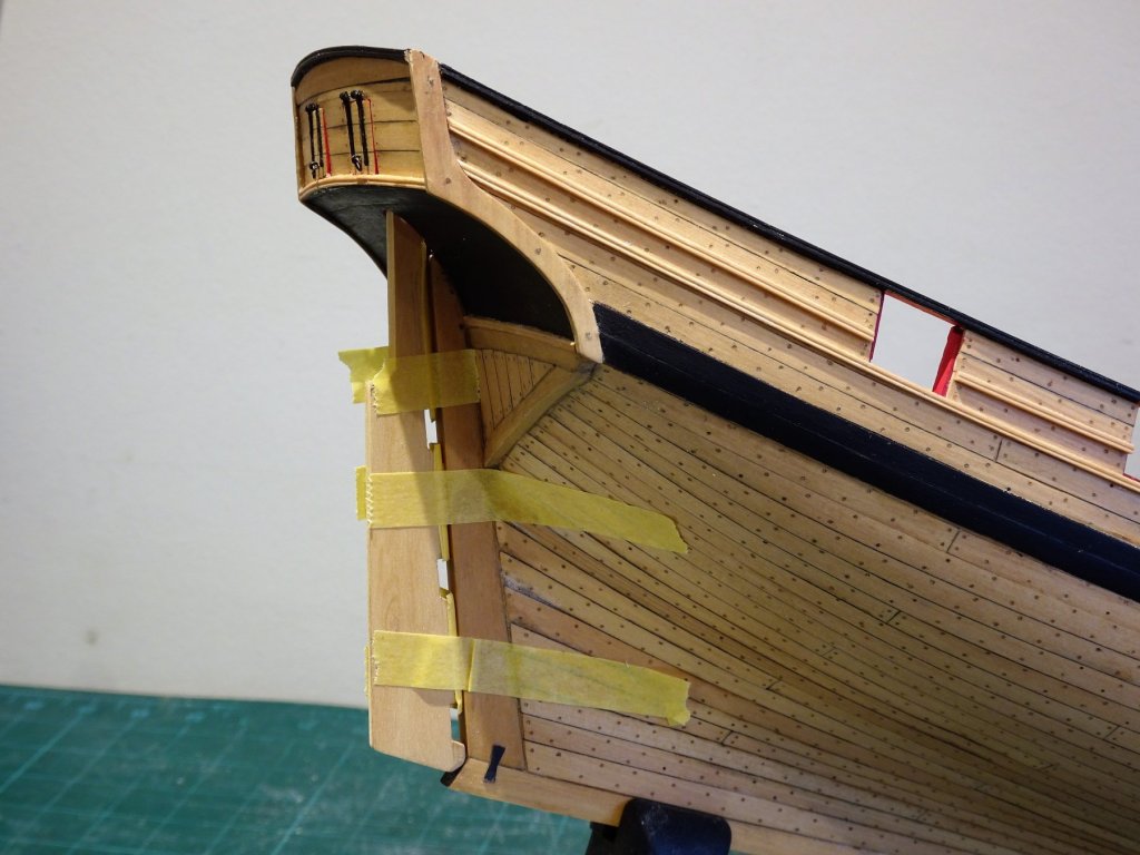
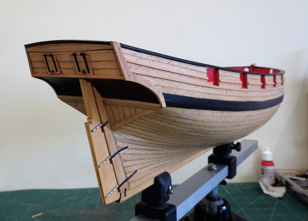
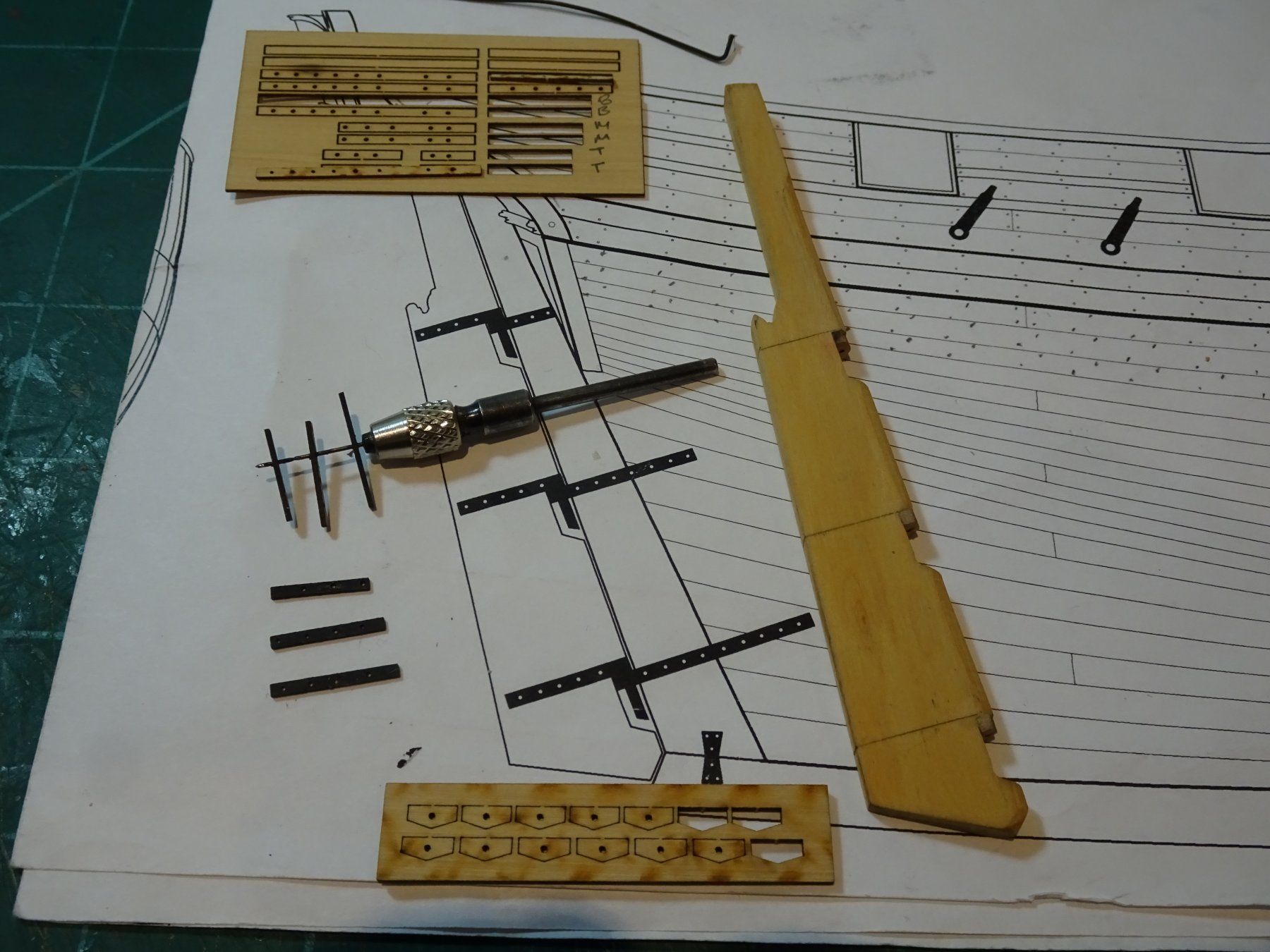
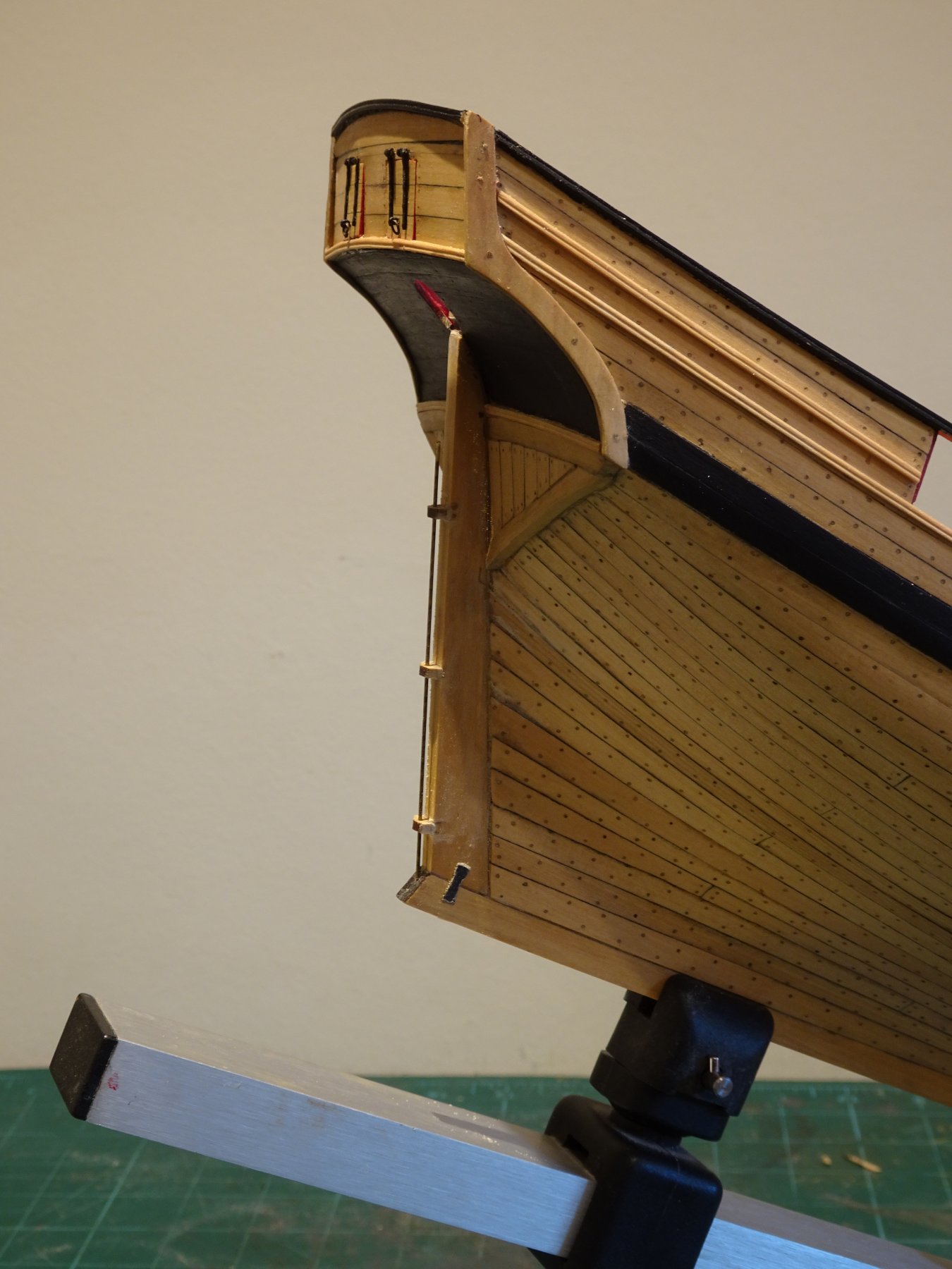
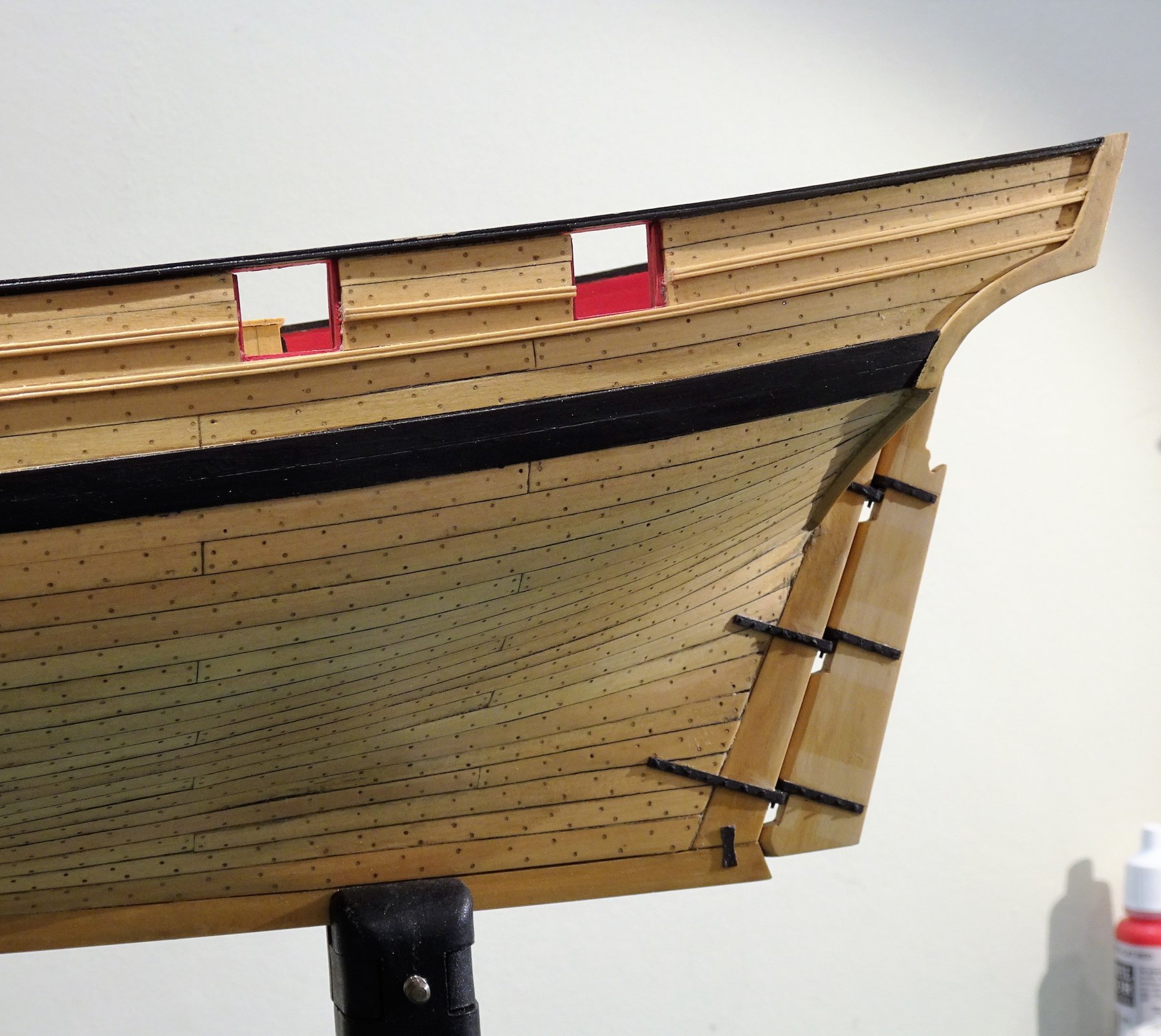
Post 55 Shipping the Rudder Following Chuck's lead the rudder is shaped to allow fitting of the 'false' stern post head. I had much earlier cut out the rudder port. 4846 Temporarily fitted to assist fitting the false stern post head. 4850 Sternpost head fitted. Earlier in the build than indicated I carried on to complete the rudder 'ironwork' and straps to reach the point of shipping it into its proper place. 4892 I am using Chuck's mini fitting kit for the purpose; the Boxwood straps and brackets. This is another ingenious offering from Chuck, saving a lot of hassle and fiddling around with brass strip, silver soldering, and metal blackening. Not that I don't enjoy those aspects of a build, but where I can obtain a simpler option with comparable or better results, it's a no brainer for me, and I'm happy to take advantage of such offerings with all the enthusiasm of a rat spotting an unguarded hawse line. 4904 In this photo the Pintle braces have been applied and the bolts represented by wire. Fitting rudders can be a tricky business, aligning the pintles and gudgeons whilst ensuring that the gap between the rudder edge and stern post is minimal. On too many models the gap between rudder and post is far too wide. On the kit plan the gap is a mere 0.5mm which equates to just shy of 1" at full scale. Chuck's little kit takes much of the guesswork out of the issue by providing the brackets for both pintles and gudgeons along with their respective straps. 4910(2) With the pintles in place on the rudder, the gudgeon brackets can be slipped onto the pintles and the rudder placed in position against the stern post. The position of the gudgeon brackets to be fixed to the stern post can then be marked, and the gap be adjusted. I did add thin strips to bulk out the depth of the gudgeon brackets to produce a workable gap between rudder and post. 4920 I then used pva to stick the brackets to the stern post, using a length of wire to maintain their line. 4924 Once set the rudder pintles should slot cleanly into the gudgeons at the correct level, always a satisfying moment. 4928 The final job is to attach the gudgeon straps to the hull at the correct angle, which is easy with the rudder in place. The straps were thinned down a little towards the inboard end, pre-painted, and secured with pva plus the 'wire' bolts coated with ca. 4929 A needle file is used to take the roughness off the wire ends before masking and repainting. 4938 The completed rudder assembly; the pale marks are where the rudder was masked for final painting of the straps. I will return to the rudder to fit the tiller a little later in the build. I have been pondering whether a Rudder coat would have been used on a small vessel such as this, where the rudder head is not passing betwixt decks but only onto the open deck. None of the photo's of contemporary models I have show this feature, but then even models of larger vessels mostly don't show a Rudder coat. Another question without an obvious answer. B.E. 18/12/2018


.thumb.JPG.74cea5d95700ac3a2333d6c503c3f50f.JPG)


- 574 replies
-
- 20
-
-
- cheerful
- Syren Ship Model Company
- (and 1 more)
-
Ha Ha Martin, I find myself in a constant state of decision constipation on this build, but I’ve gained some temporary relief by kicking the decision into the long grass for the time being. 😀 B.E.
- 574 replies
-
- 1
-
-
- cheerful
- Syren Ship Model Company
- (and 1 more)
-
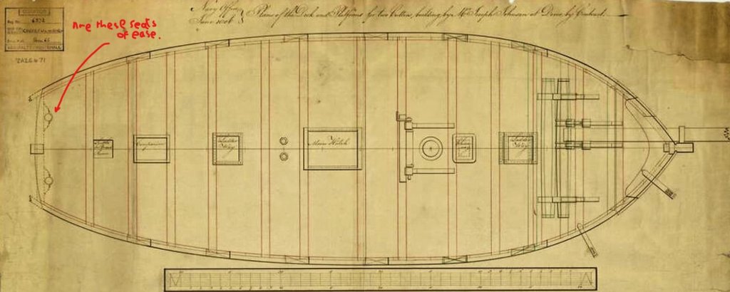
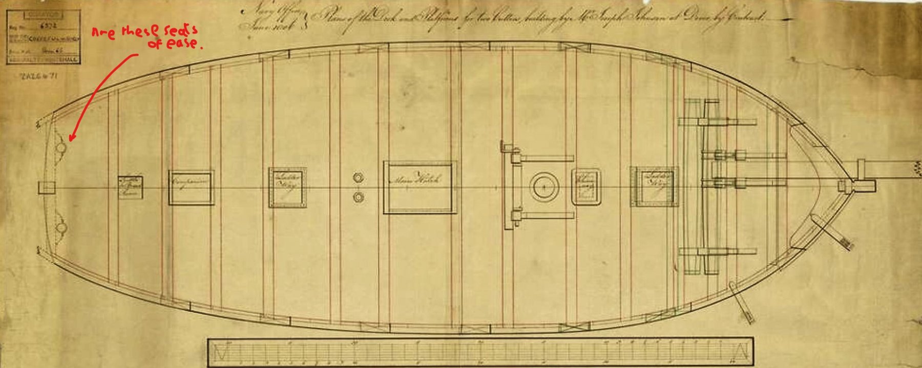
Hi Paul, if you're referring to the official inboard profile plan, I don't see either the cap rail level seats or the second cathead, perhaps ignorance is bliss😉 B.E.
- 574 replies
-
- 2
-
-
- cheerful
- Syren Ship Model Company
- (and 1 more)
-
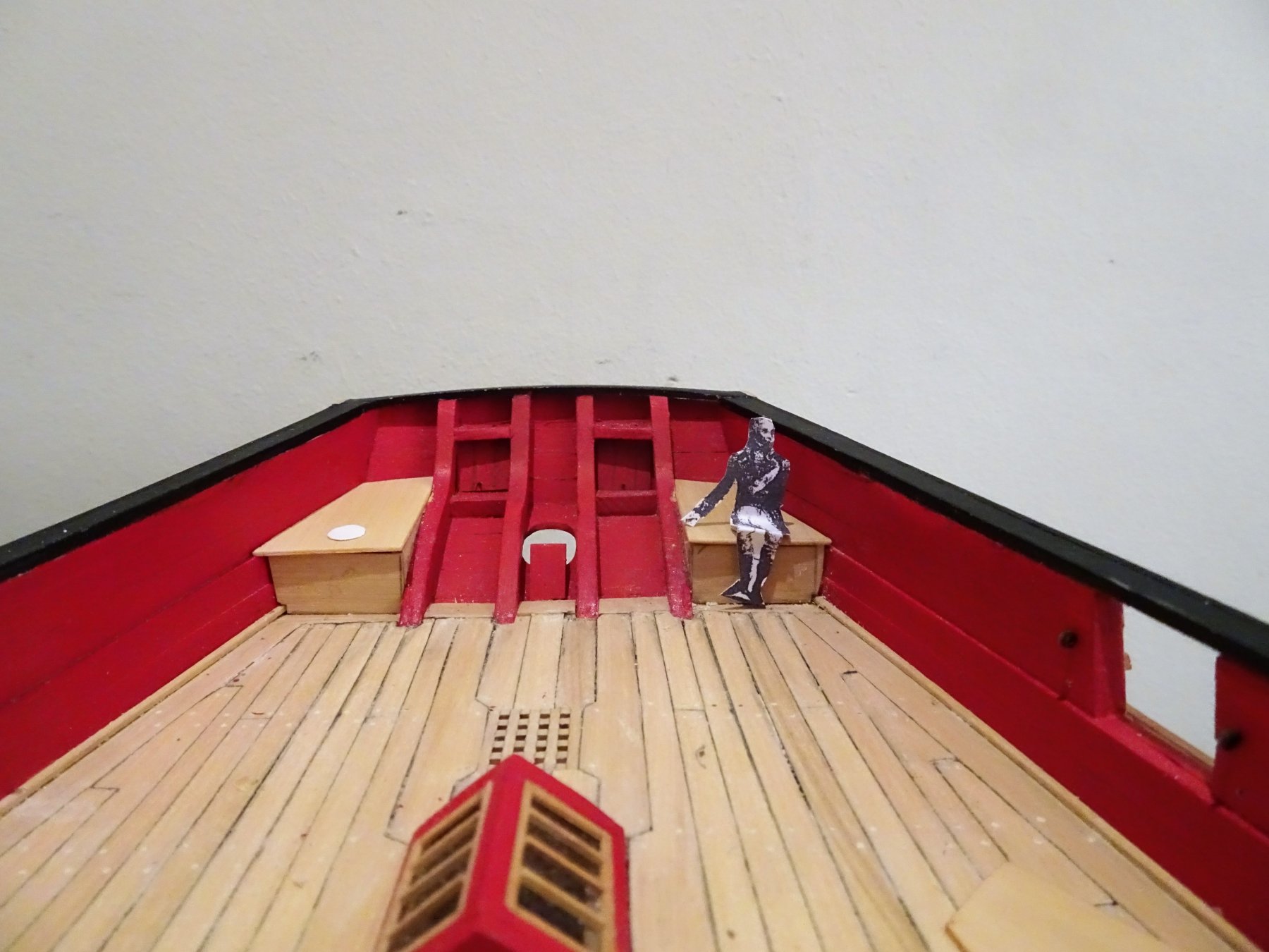
Thanks Guys for your input. @ Paul, Yes I have read that, I think it was a comment in one of other Cheerful logs. The arrangement of one seat of ease and one locker makes sense to me, somewhere to store ready to use small items, but I'm 200 years down the road, so what do I know🤔 @ jnugid, On examples I have seen including the small platform across the counter on the Cutter Alert, the boards run athwartships. The areas on Cheerful are not that large, around 4' 9" x 2' 6" but I don't know whether a solid sheet or boards would have been used. @ Dave, I will also add a discharge chute, purely for my own amusement. I think this would taper, with the exit thro' the counter planking somewhat smaller than the top opening. @ Chuck, Two heads for a crew of around fifty does seem very generous in 18th century terms. I haven't actually seen a detailed photo of the Surly arrangement, but to duplicate it on Cheerful would be the logical thing to do, in the absence of more compelling evidence. On reflection those fittings shown on the plan of Cheerful, do look more like as you describe. On checking I see that on the Cutter Alert plans (Peter Goodwin) similar fittings are shown; they are described as a step block and bracket to hold a Mizen mast. @ Peter, thanks for checking out your photo's and for providing that very clear photo of the stern area. For the time being I think I will leave the seat tops as removeable items, no need for a decision at this point. Regards, B.E
- 574 replies
-
- 2
-
-
- cheerful
- Syren Ship Model Company
- (and 1 more)
-
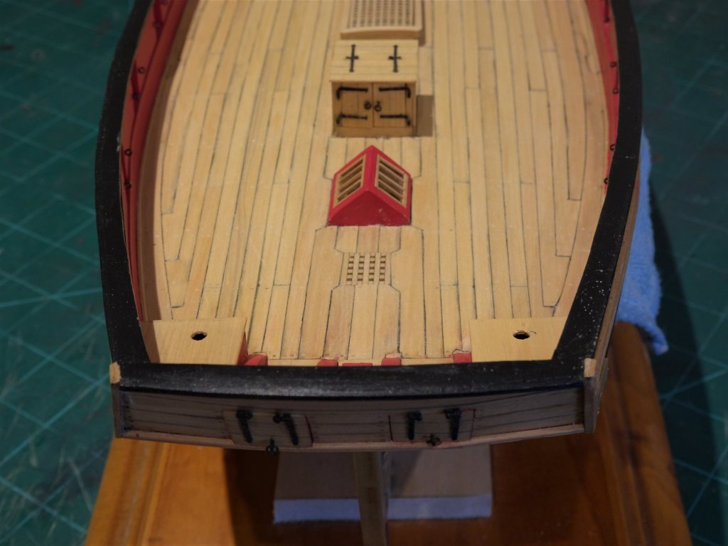
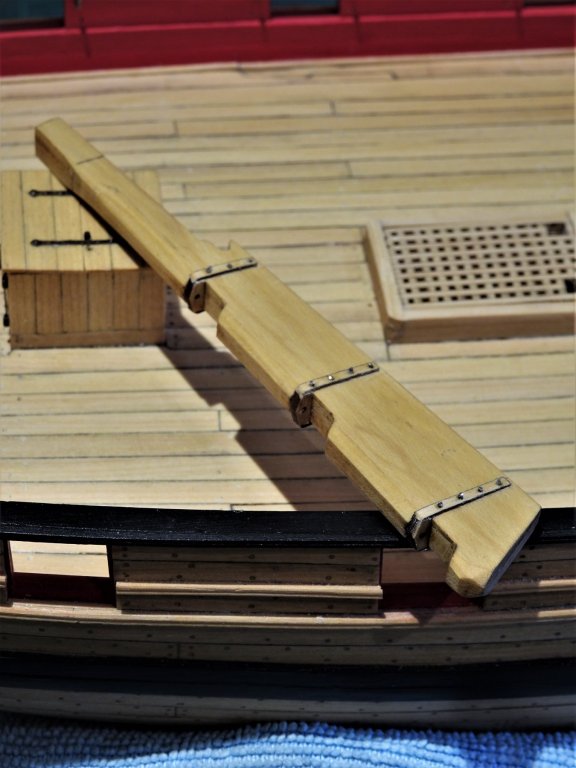
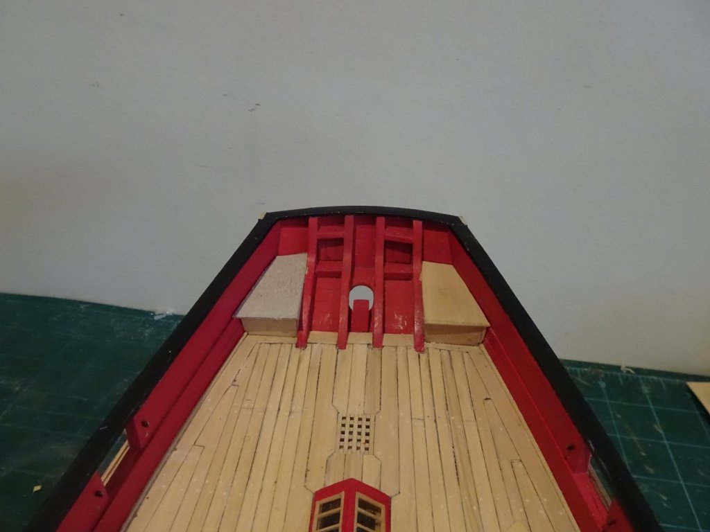
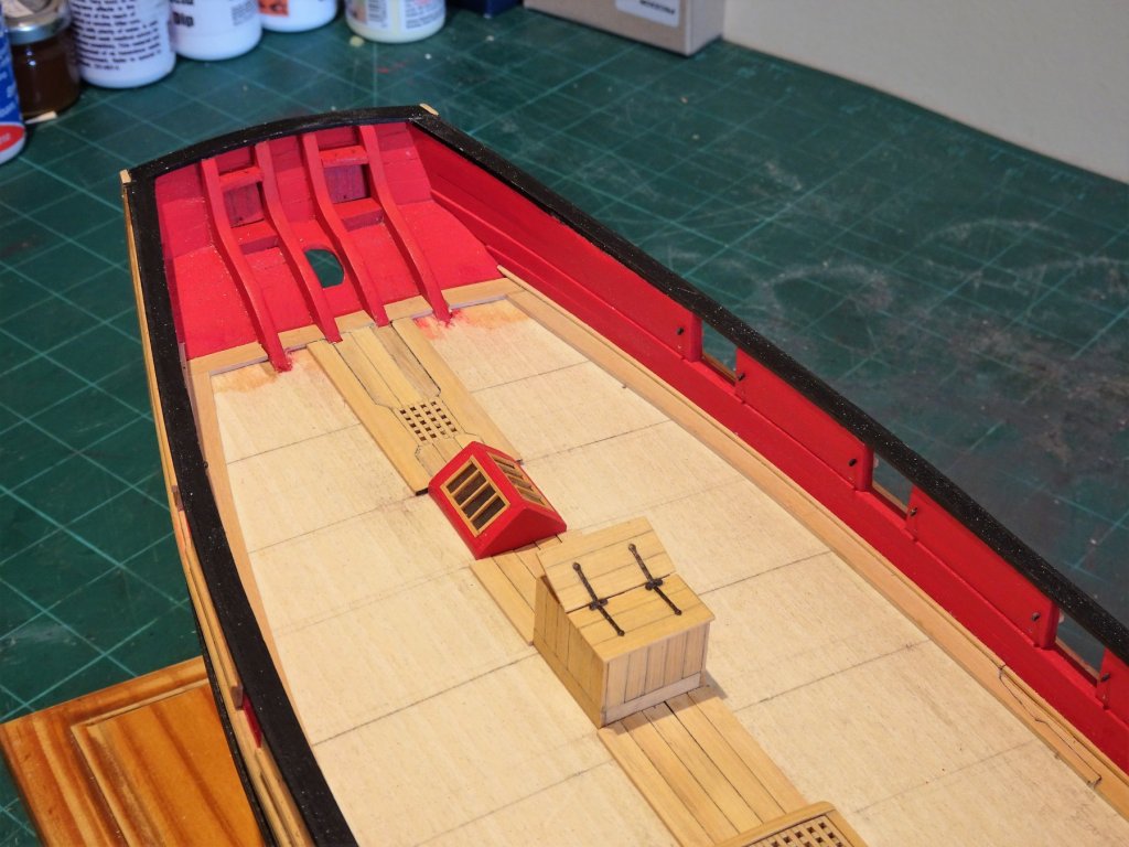
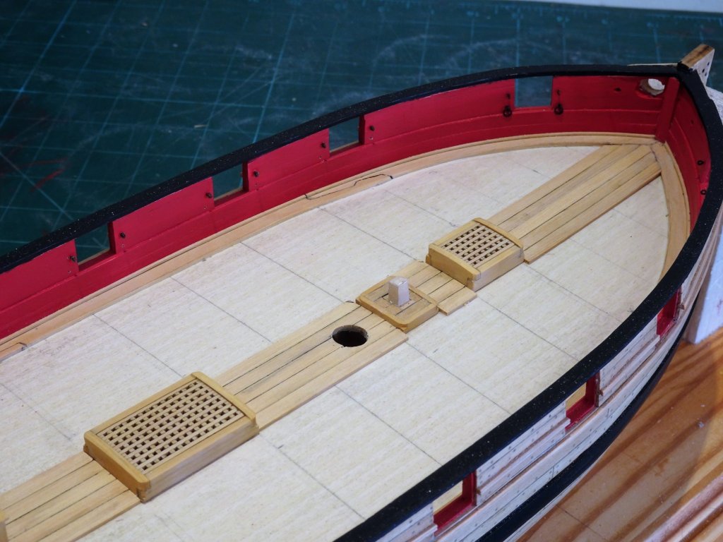
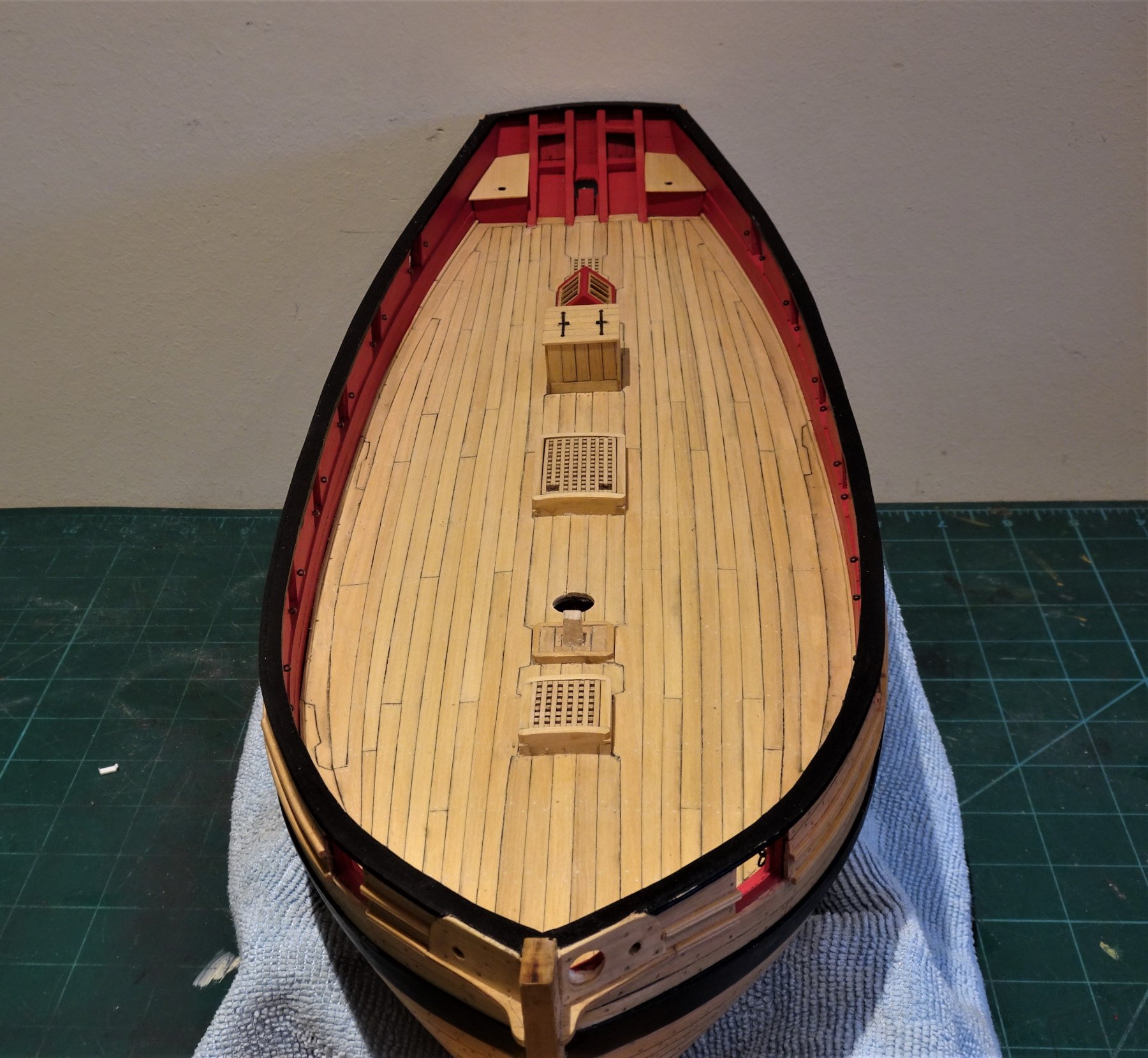
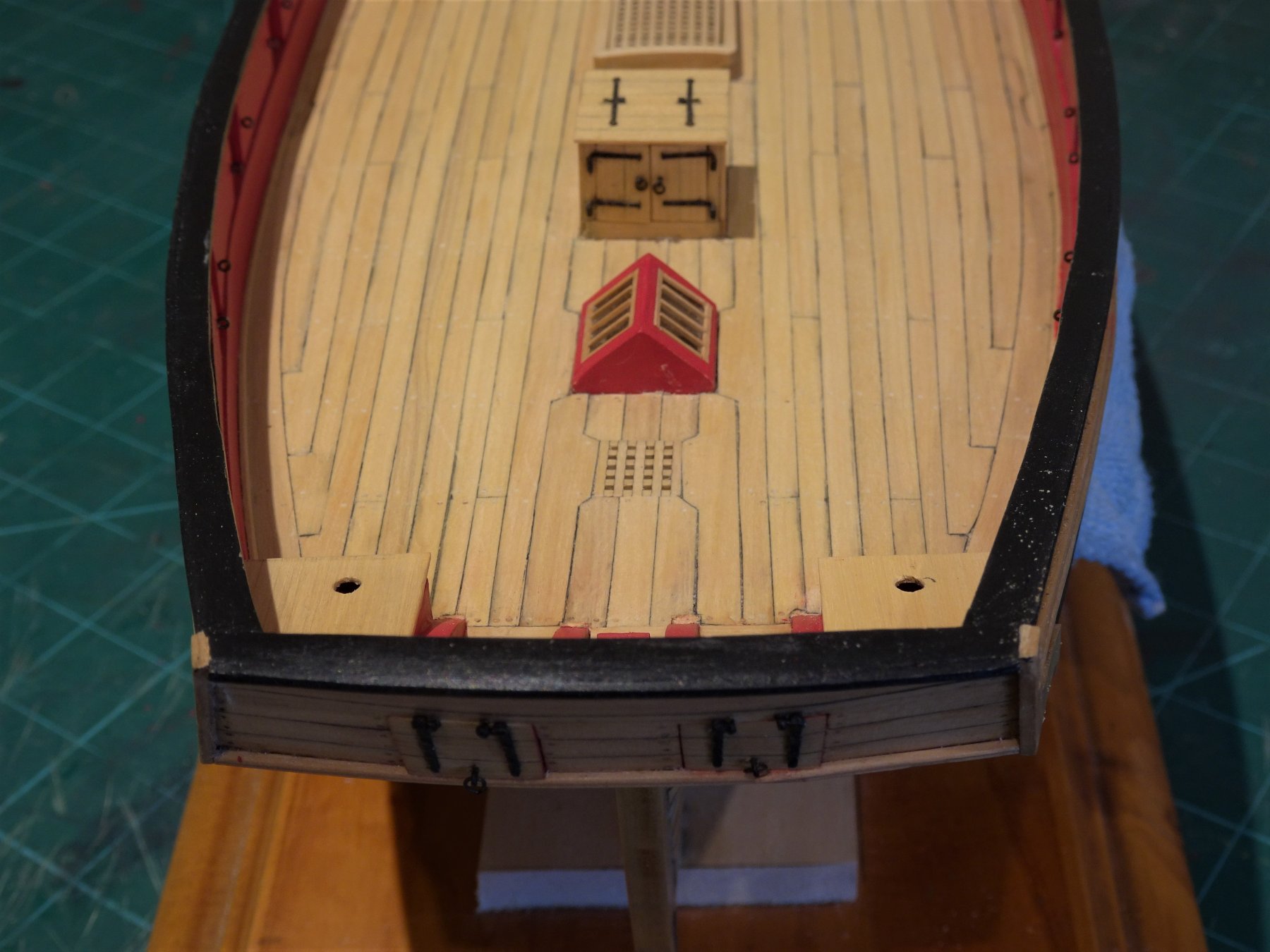
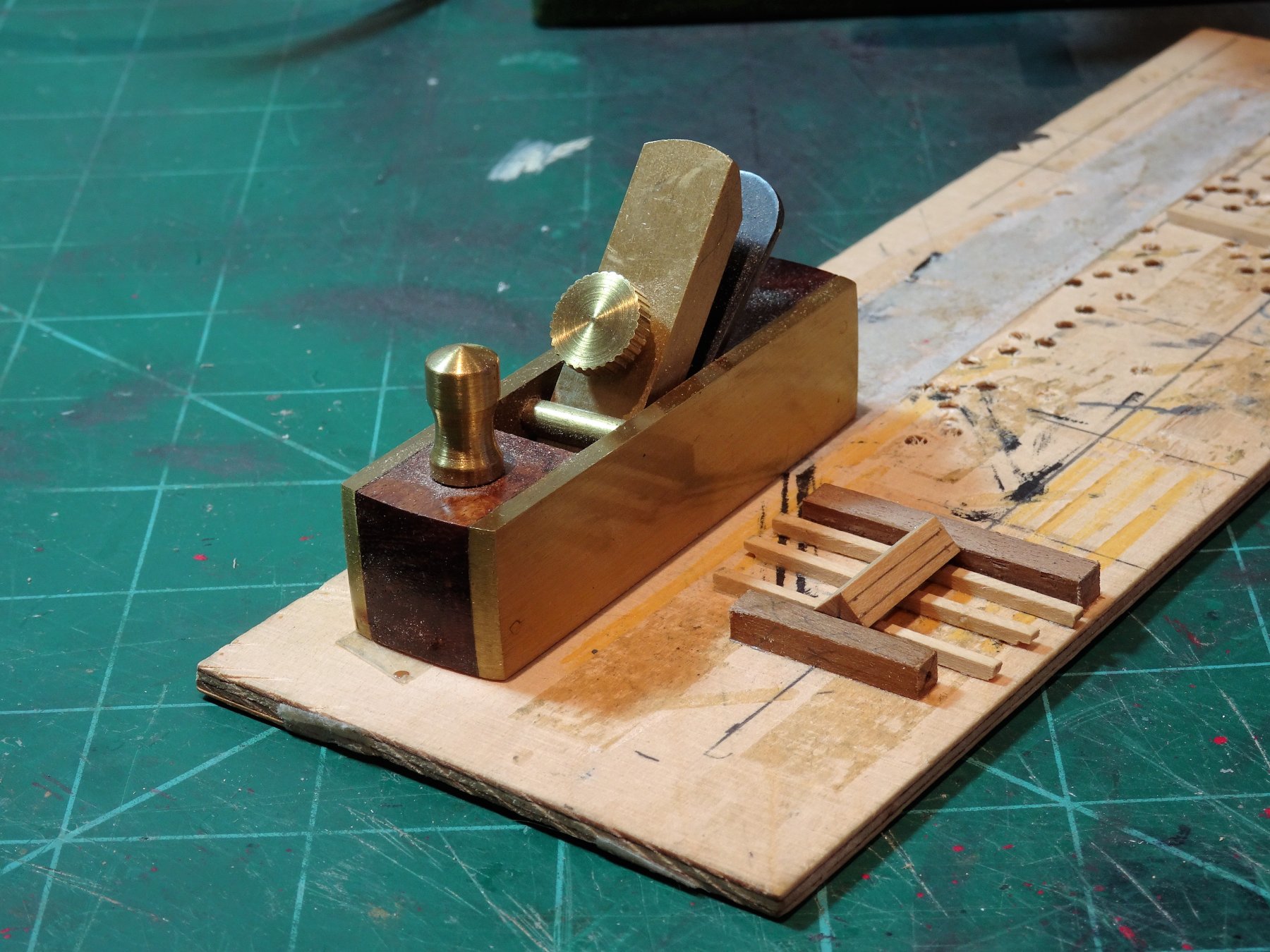
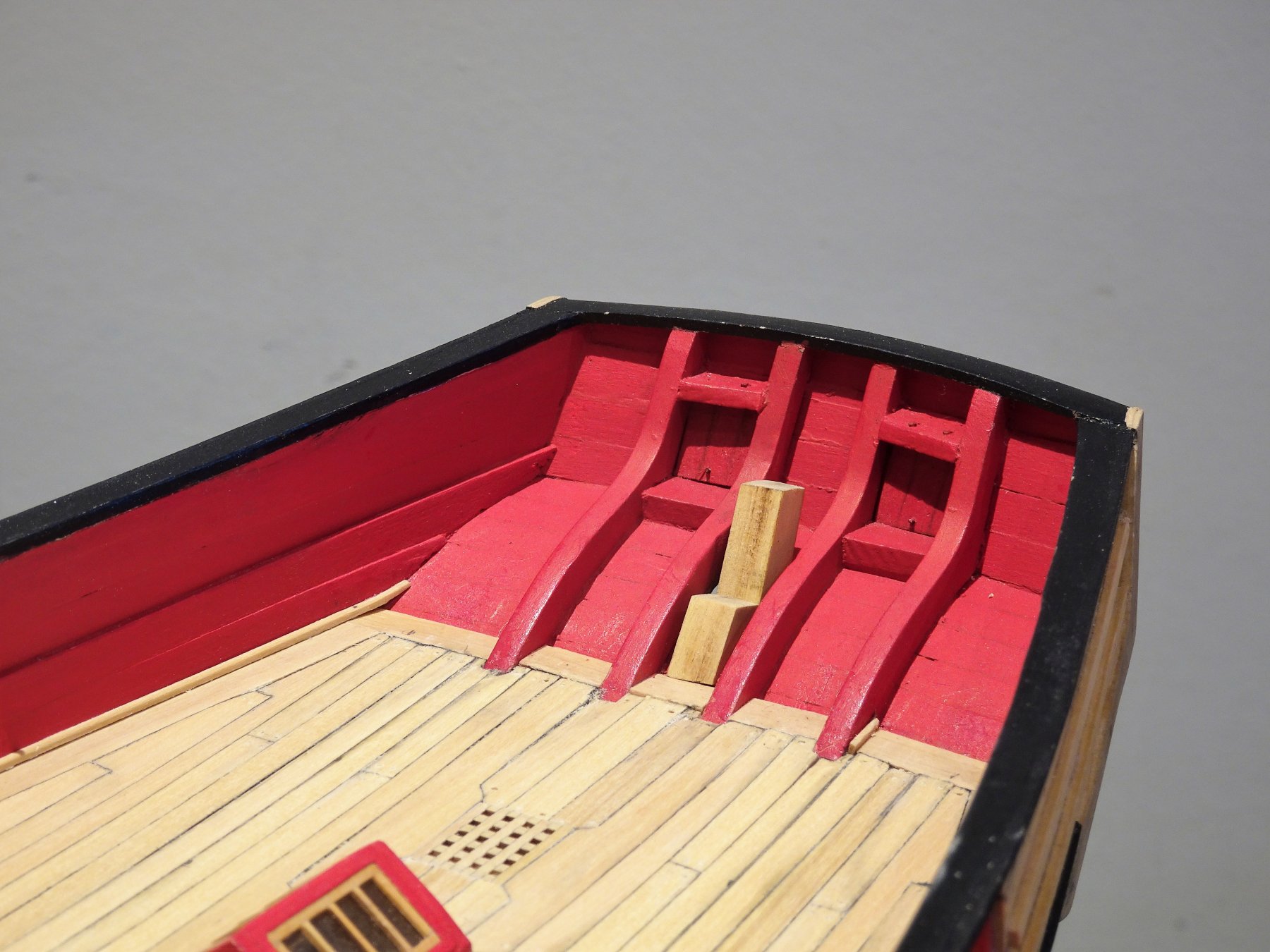
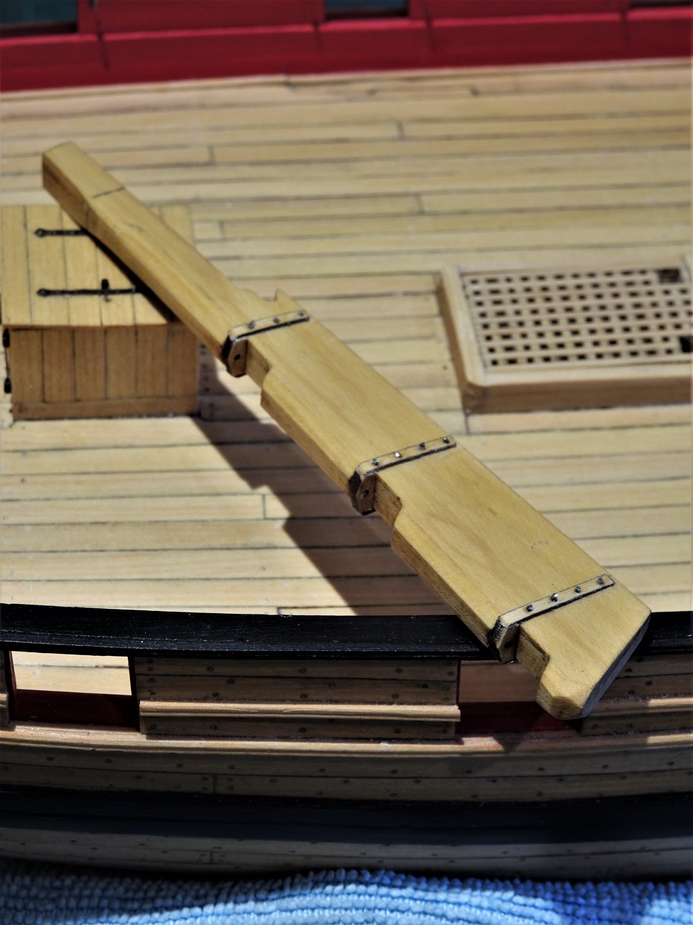
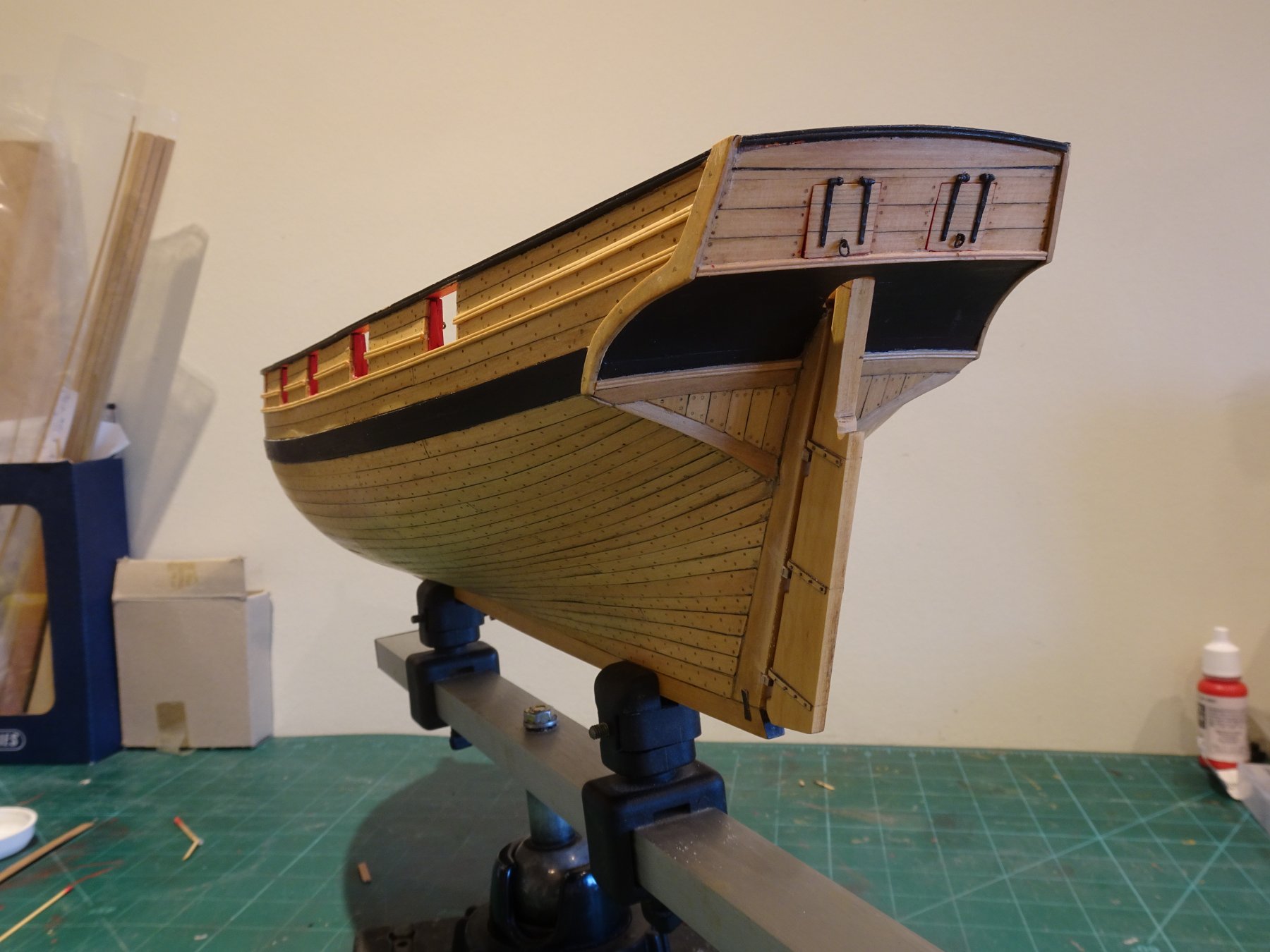
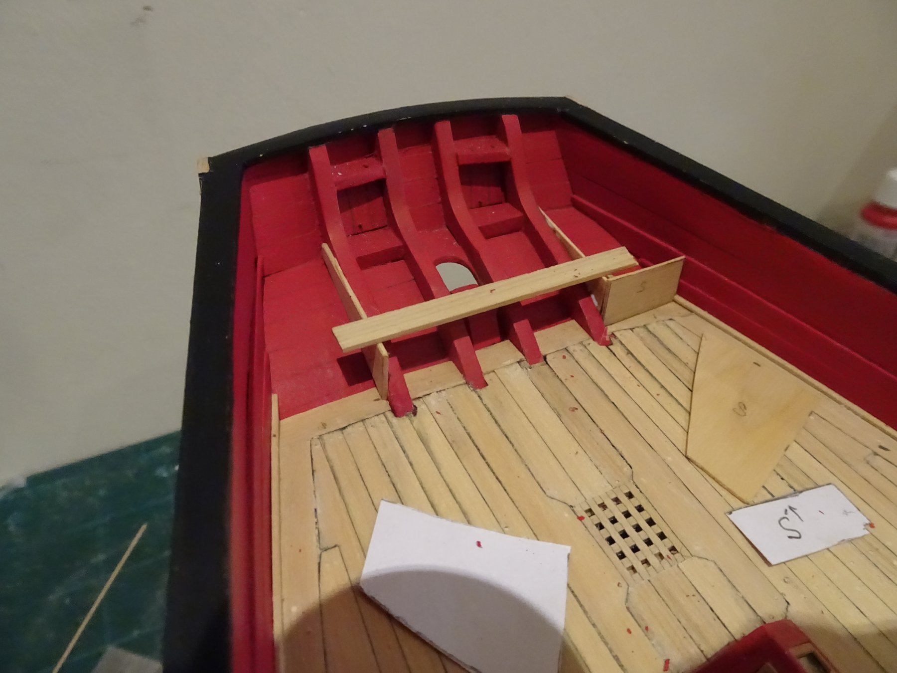
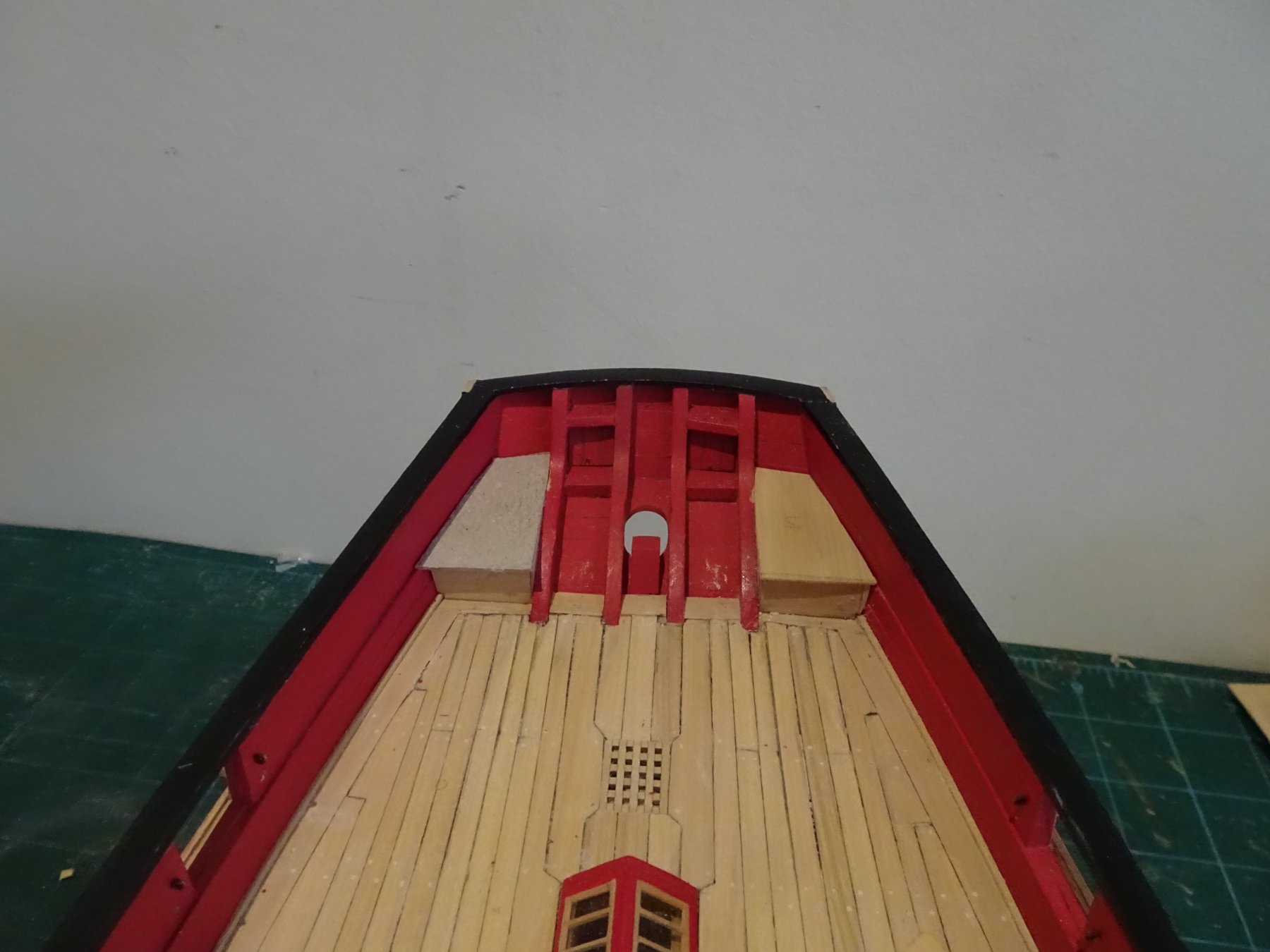
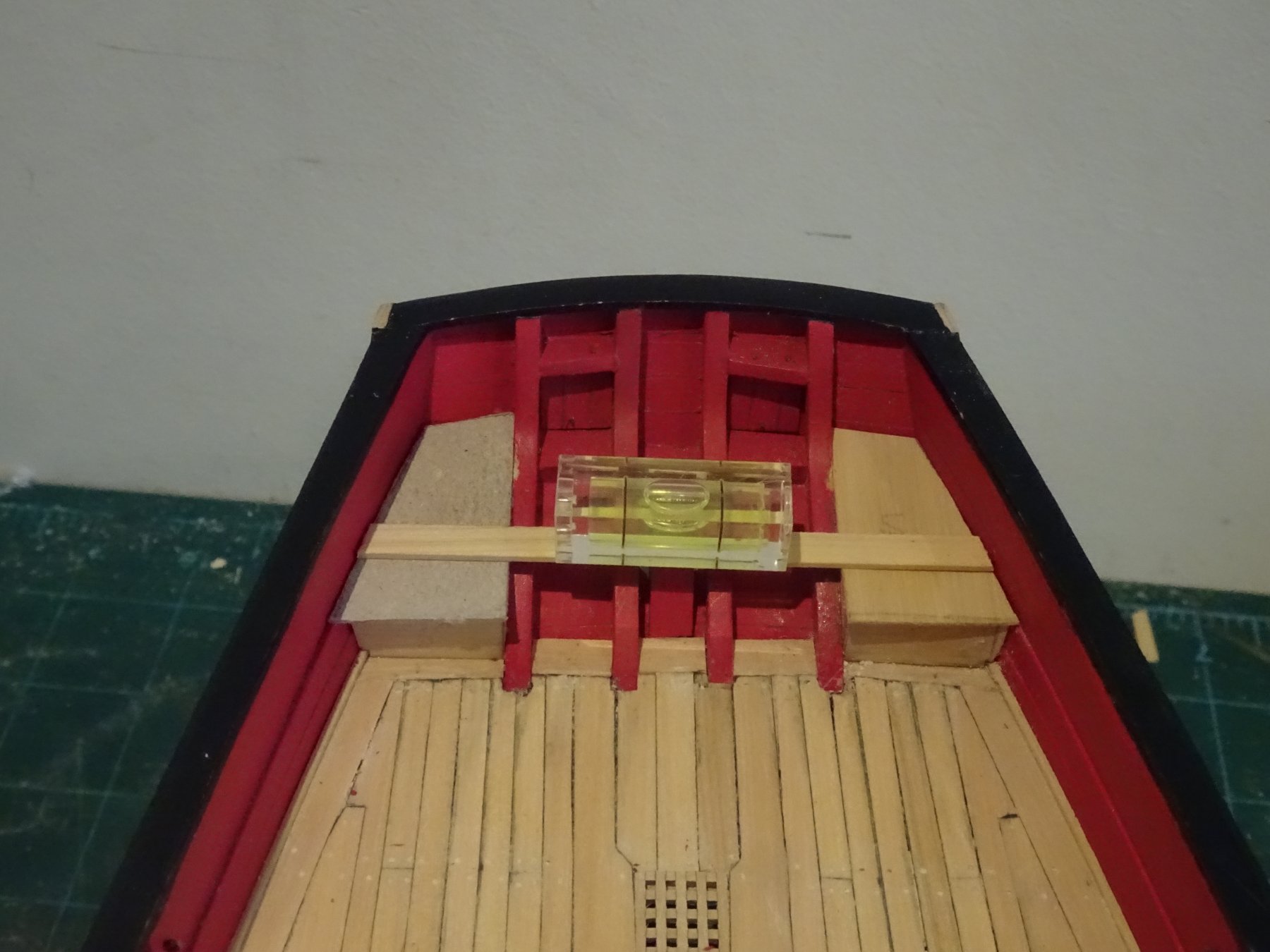
Kind words, thank you Wallace and Martin. 🙂 Post 54 A question lavatorial I now turn my attention to the stern area to fit the platform containing the 'seats of ease' Chuck has used 1/32" sheet to form the construction parts, as have I. 4857 A trial and error (mostly error) job this with multiple tweaks to get it anywhere near right. 4876 Fitting these surely does mess up the paintwork at the stern, re-finishing will be required. 4877 Chuck has included two 'seats of ease' at the stern of Cheerful; seems quite generous considering that a first rate only had six for the whole crew, excluding officers. I had wondered about the prominent position of these 'facilities' at the stern as modelled, but these items as shown on the Upper deck plan of Cheerful, appear to be 'seats of ease' Upper deck of Cheerful. The holes on the model plan initially looked quite large to my eye, but they are only a scale 7.5" diameter. As for position on the platform I requested the Commander to check that their location provided a practical seating position. 4879 He seems quite at ease. Apparently in naval circles it was considered good manners to use the Lee side seat of easement if at all possible. Anyway I digress, I wonder if in reality these small platforms would have been planked rather than solid sheet? I also wonder if in practice they would really have been painted, presumably being scrubbed down and also used for access to the Taffrail, or a height advantage point on the cutter. All speculation of course , but examples of cutters I have seen with small aft platforms all were planked and in some cases used to mount Stern chasers. 4888 Purely for my own amusement I planked over the card template I used to make the platform using thin boxwood strip, to see what it looked like before I committed to the real thing. Once again obsessing over minutiae, to paint or not to paint, to plank or not to plank, one hole or two. There is such scant information on the subject, particularly for small vessels. B.E. 15/12/2018


- 574 replies
-
- 15
-
-
- cheerful
- Syren Ship Model Company
- (and 1 more)
-
Cheers Guys for your support. @ Michael An interesting question Michael that I can't really answer. I had used this arrangement on my Pegasus build as indicated in the Swan series books, and also it was the arrangement Chuck used on his Cheerful build. I can't find any clear examples of the curved /hooded planks layouts in any of my modelling books, apart from mentioned above, they all seem to show the 'joggled' arrangement. I wonder if you have in your mind the strakes of top and butt planking that were commonly placed against the margin for four strakes or so, certainly on larger vessels of the time. Regards, B.E.
- 574 replies
-
- 1
-
-
- cheerful
- Syren Ship Model Company
- (and 1 more)
-
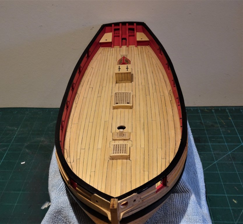
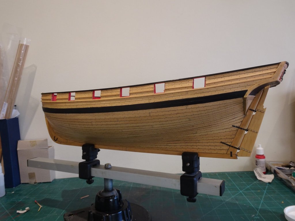
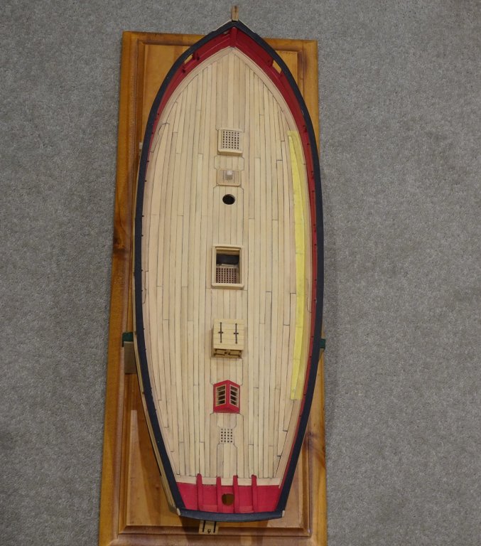
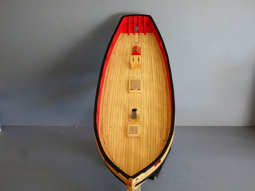
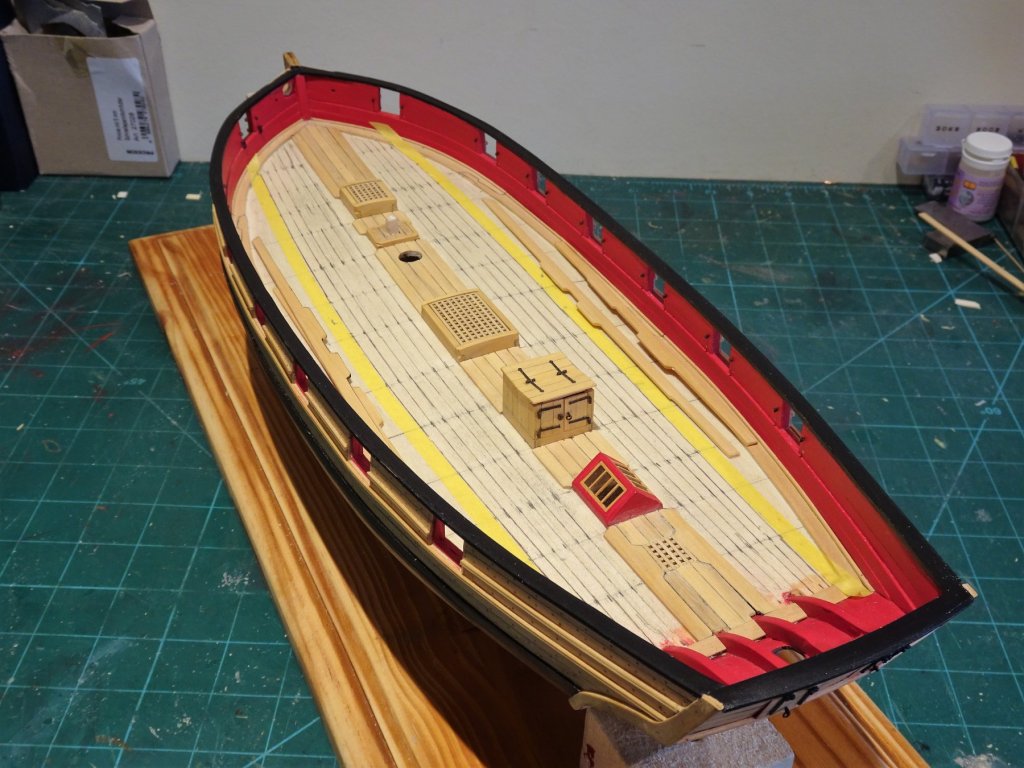
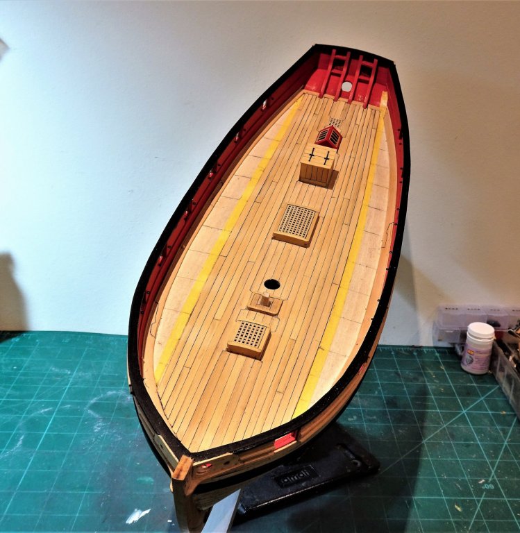
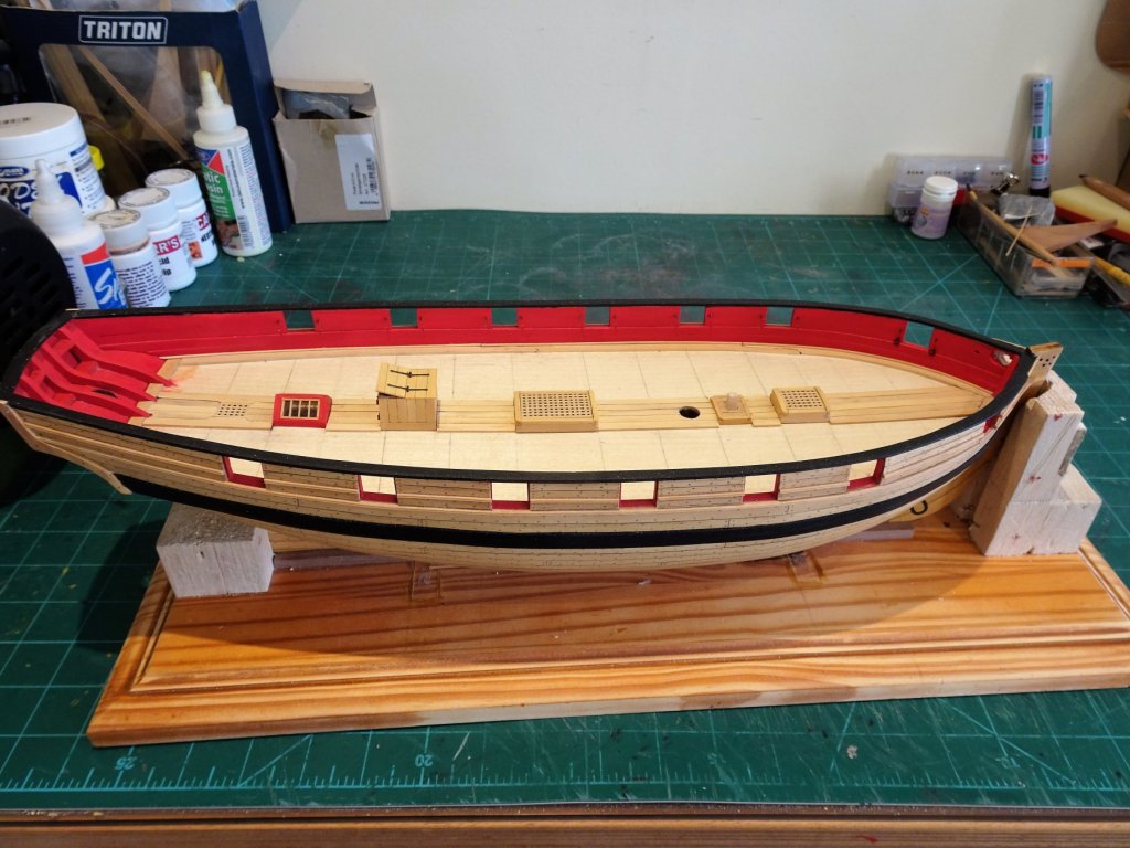
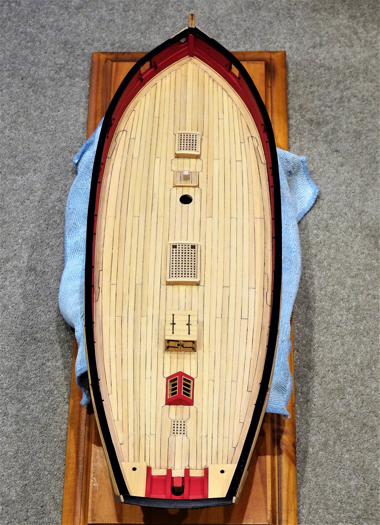
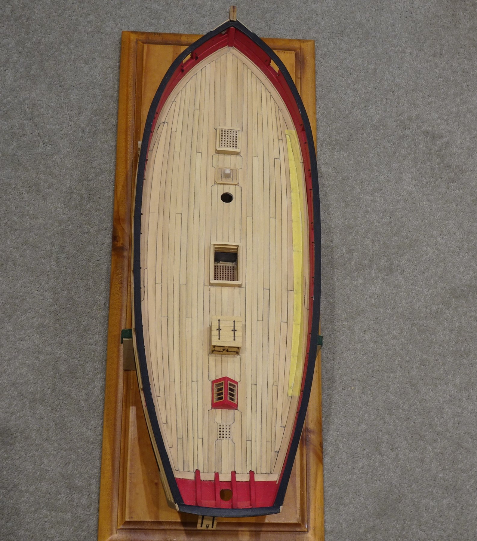
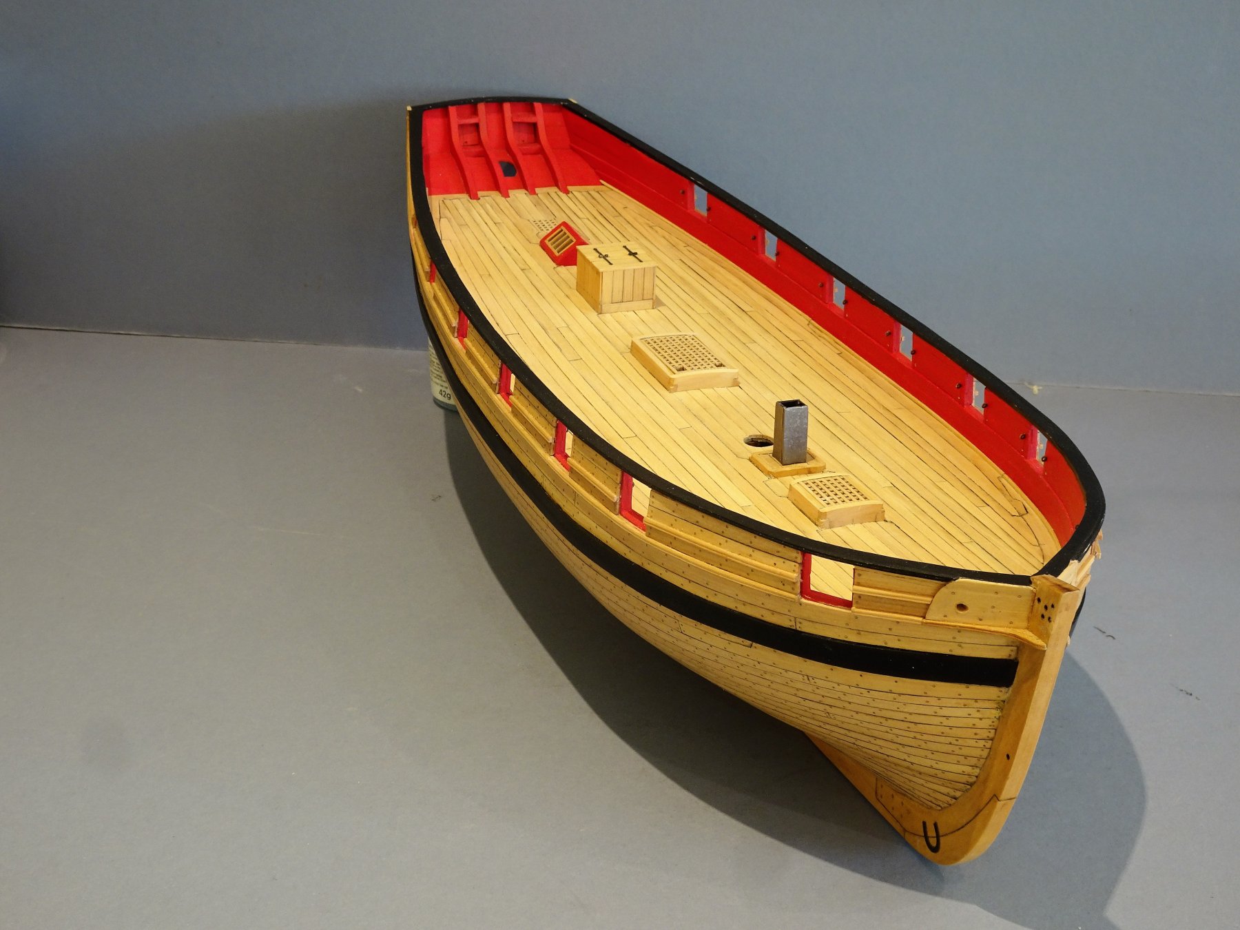
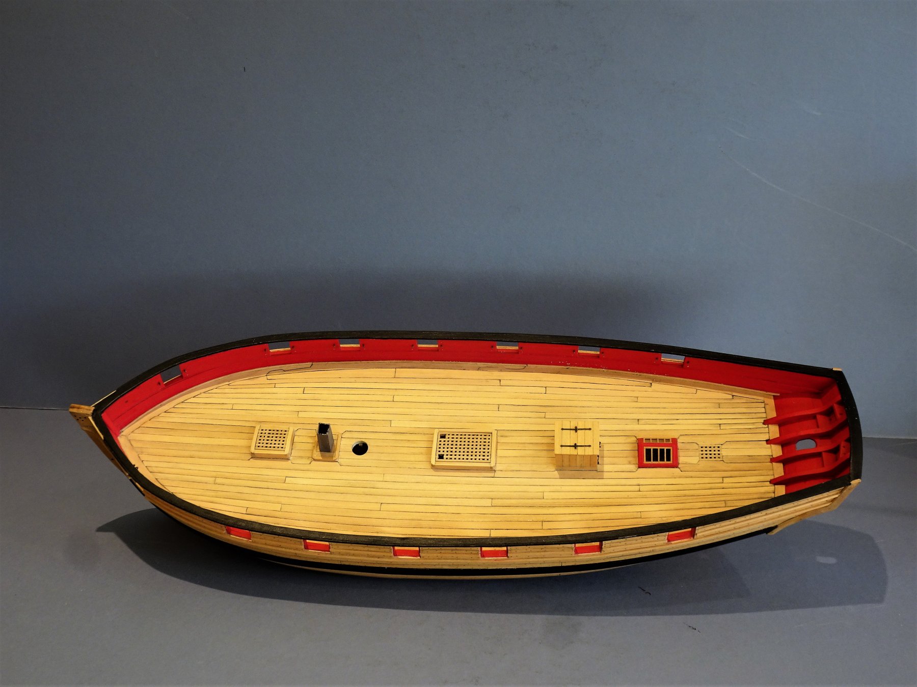
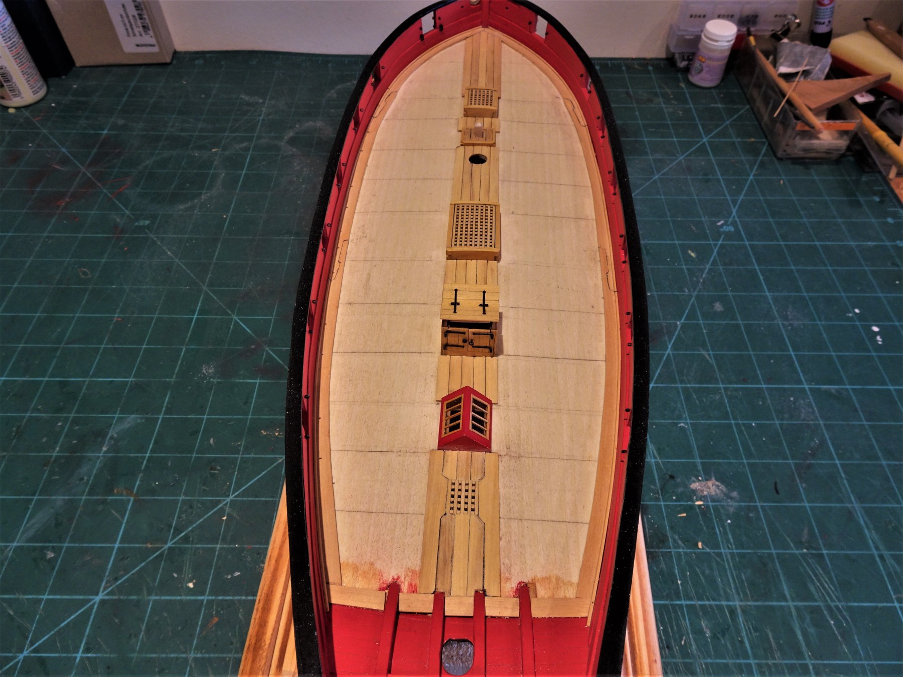
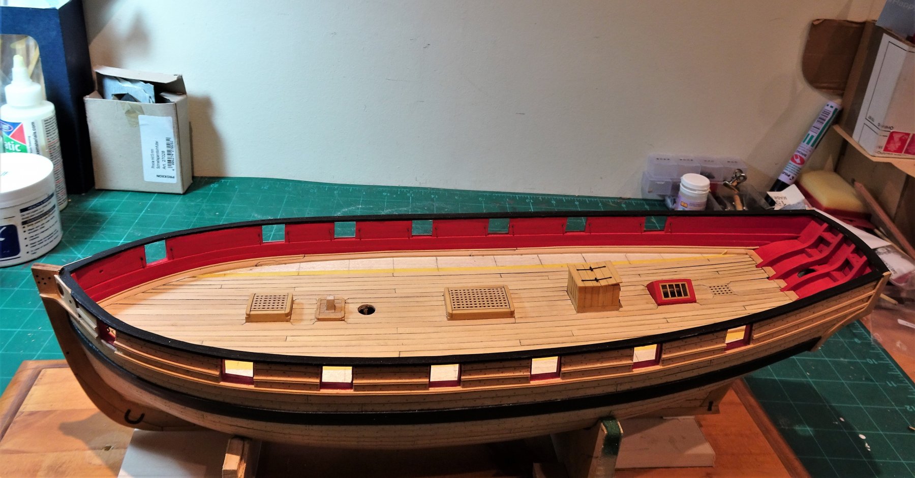
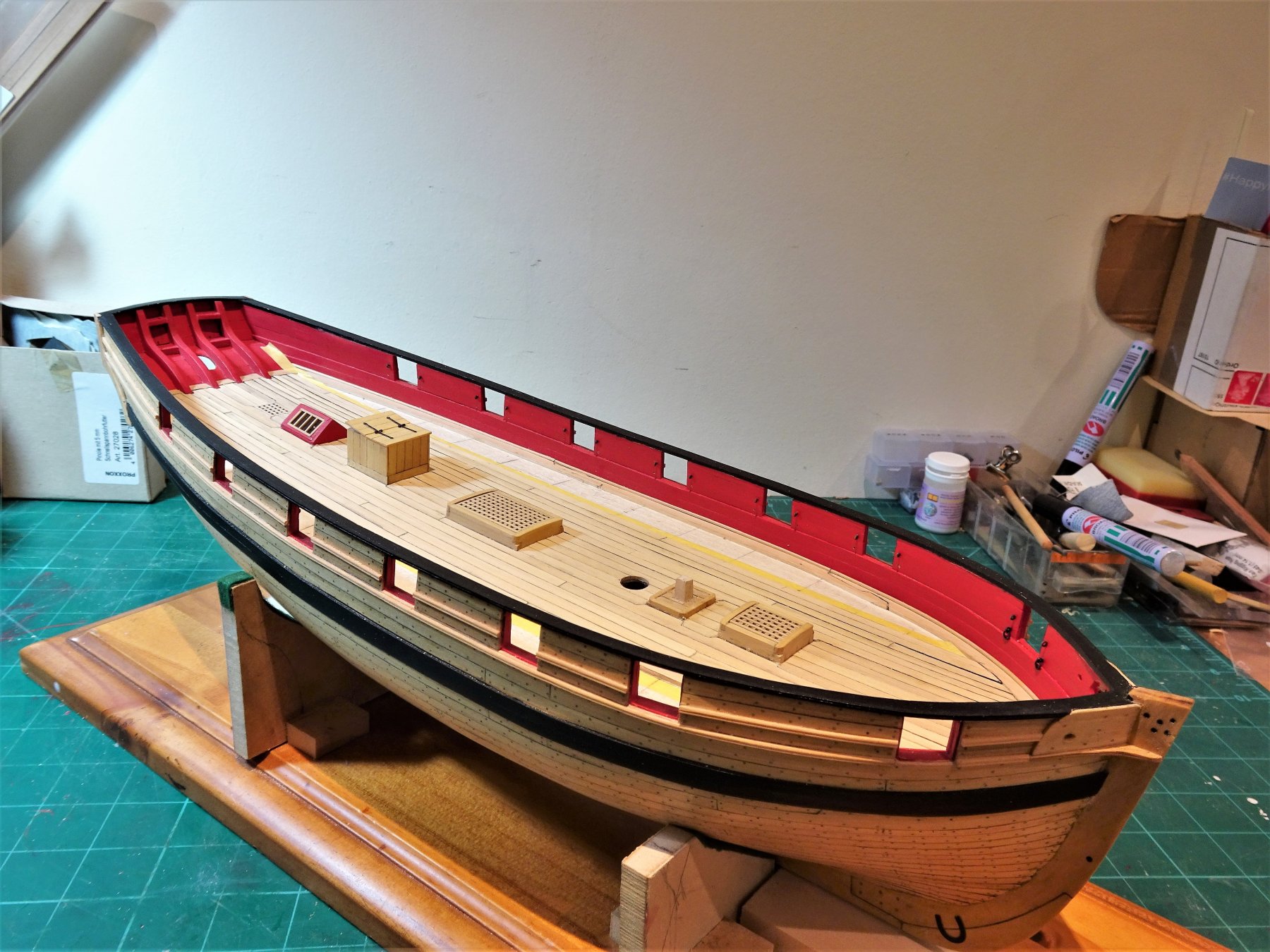
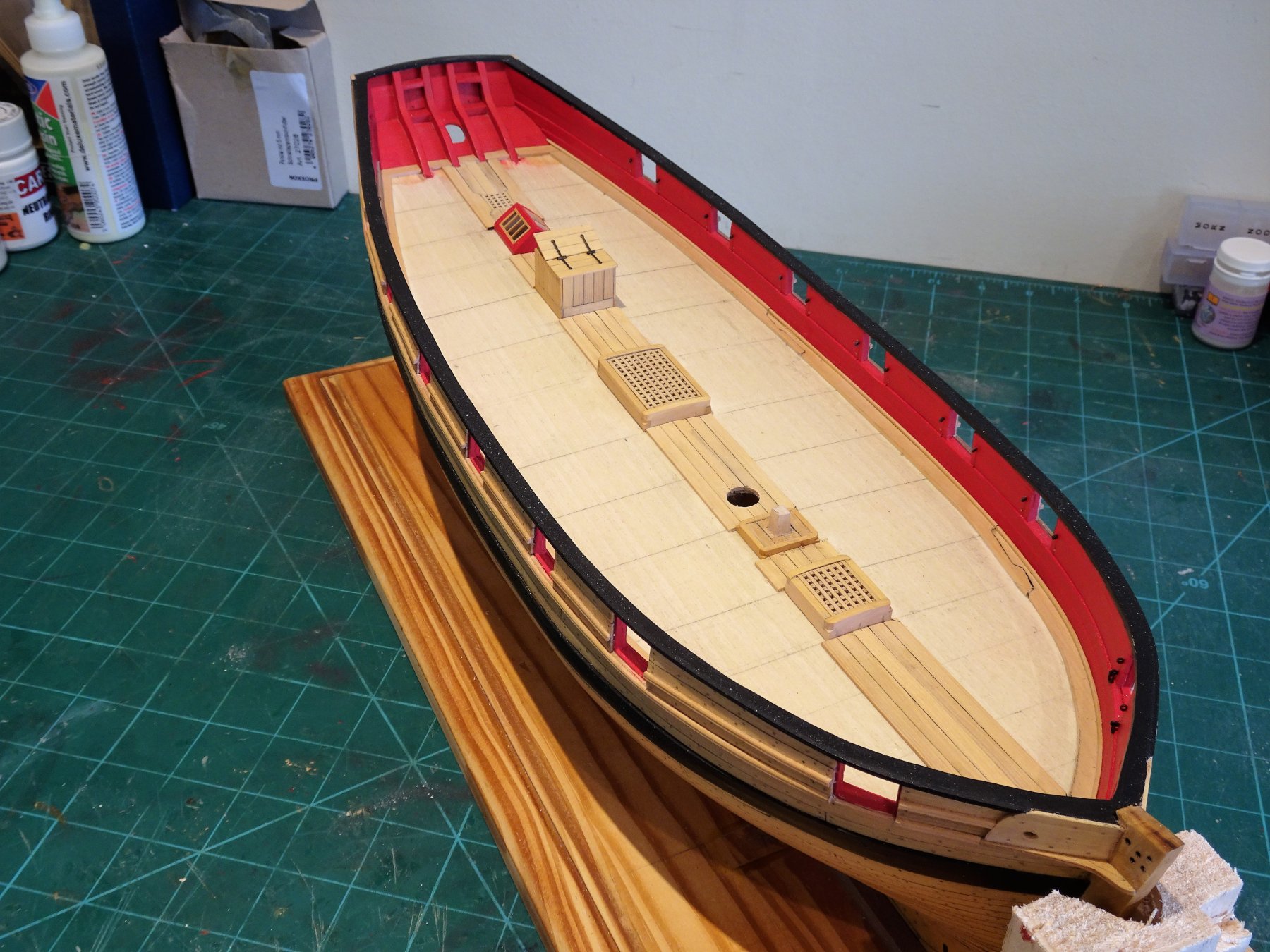
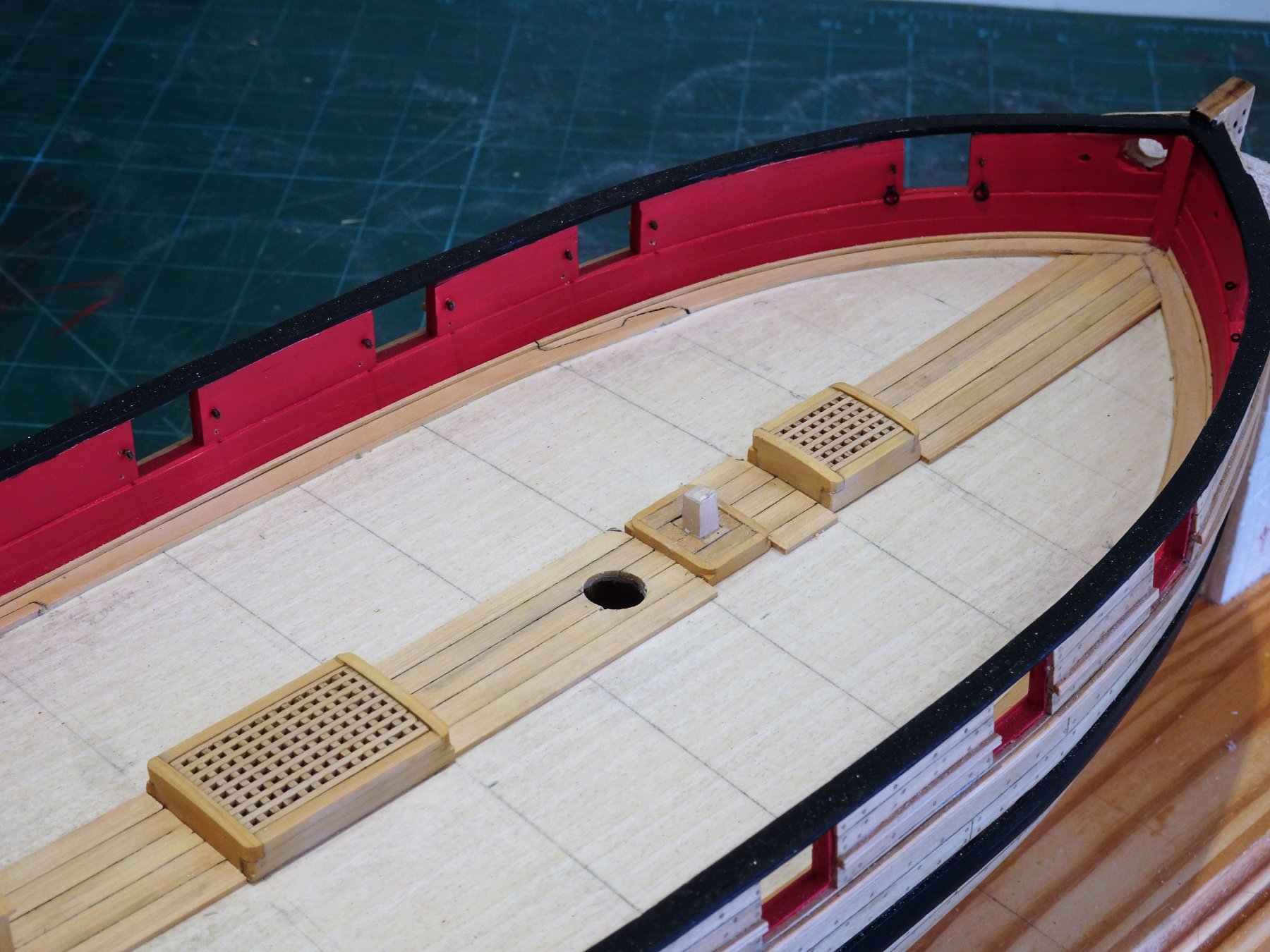
Thanks Thomas🙂 Post 53 Completing the decking. The last four strakes include hooded planks where otherwise the planks would taper too narrowly. I rather enjoy making hooded planks and they make for an interesting feature, a change from the more familiar 'joggled' arrangement. 7/32" and 9/32" wide strips were used to form the hoods, a fairly painless process. The final strakes against the margin plank also require 9/32" strips. To form these I use a Tamiya tape pattern to form a template to produce these final planks. 4807 The final plank marked for spiling. 4826 Completion! A process of scraping the decks now ensues, I don't sand decks. I will use Admiralty Flat Matt Varnish to seal the surface. Some photo's to record the twelve month point of this build so far. 4838 4832 4837 4836 The eagle eyed will notice that I have cut out holes in the Main hatch grating to allow passage of the anchor cables. 4834 This marks completion of this major milestone in the build. Fitting the rudder beckons.... B.E. 07/12/2018

.thumb.JPG.baa4d70b8ec224729c0d93ad2386aaab.JPG)
.thumb.JPG.b995bbe67daf8ca4fe759967bd75dc5a.JPG)
.thumb.JPG.886ca7fc57793233829de4a63f176776.JPG)

- 574 replies
-
- 30
-
-
- cheerful
- Syren Ship Model Company
- (and 1 more)
-
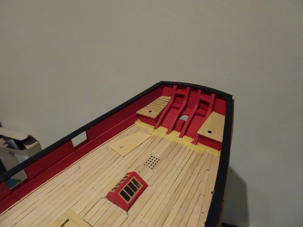
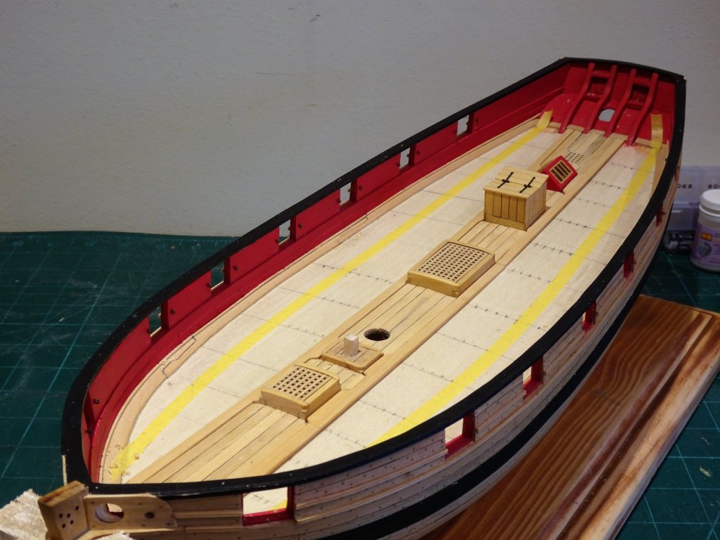
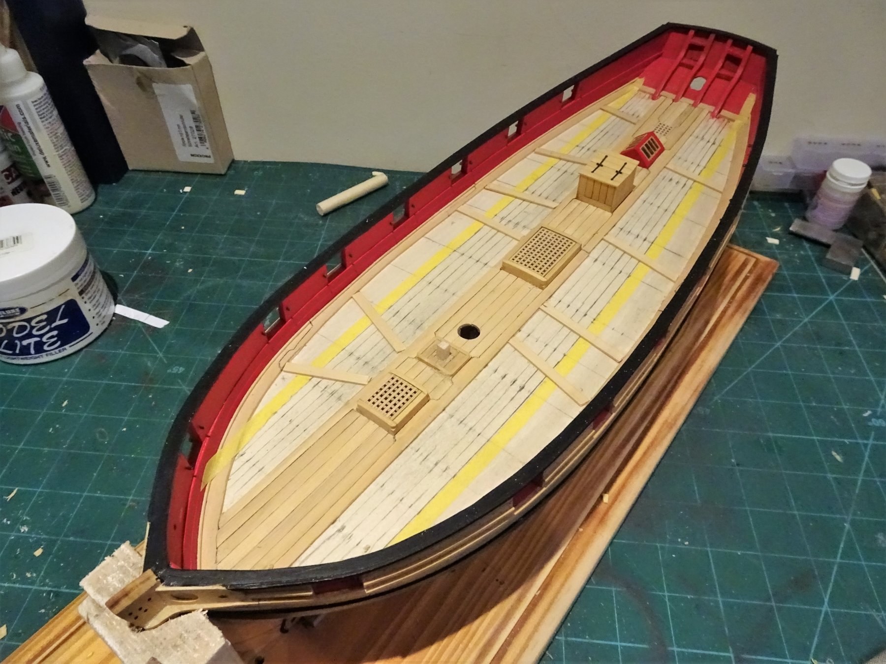
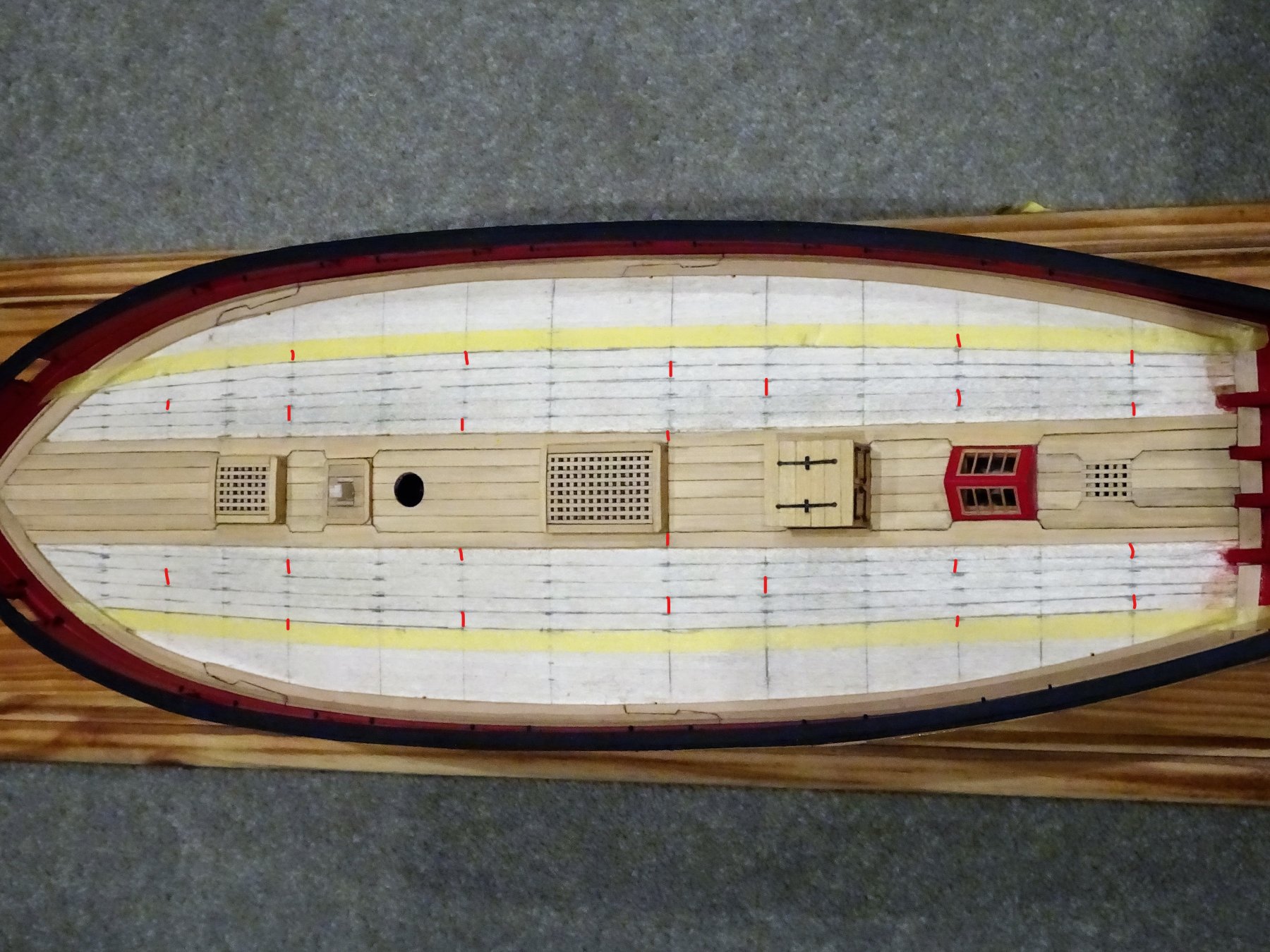
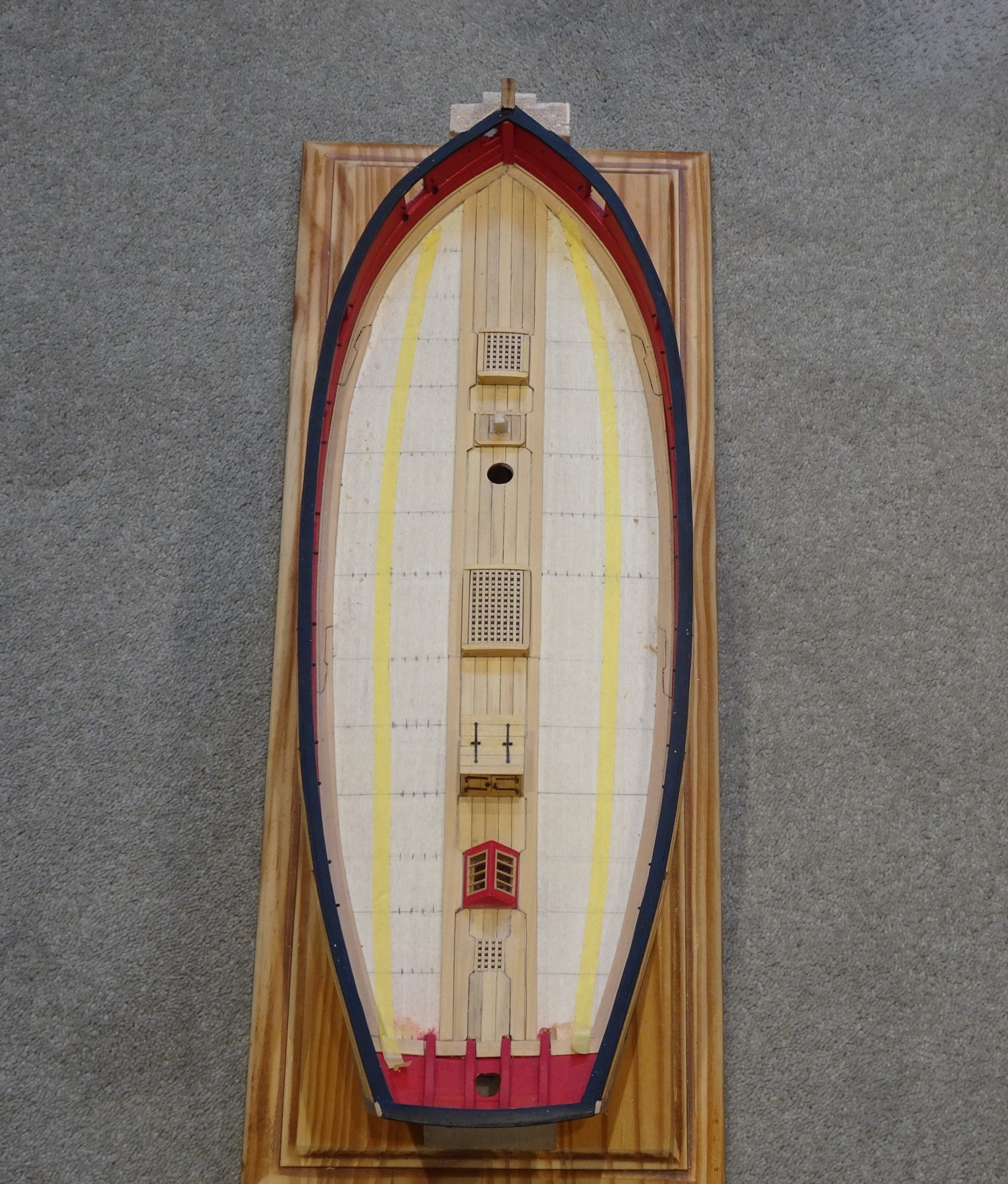
Post 52 Decking continues. With a little help from my friends 👍 issues with getting the curve right for the bandings are resolved and I can move on. The way my centre line planks worked out there is a requirement for a wider plank with tabs and cut outs immediately adjacent either side. 4724 These were tricky to form as there are double tabs and cut outs on each of the two planks that form the run. A two plank run falls within the overall acceptable scale lengths and avoids a butt joint at an inconvenient point. 4759 These planks were formed first without any consideration of tapering or bending. 4771 The inner band of planking now defined by an adjusted and less acute tape line, and the individual plank lines re-marked. 4776 The two plank lines adjacent to the centre section are now glued into place and braced during the gluing process. The next thing to work out is the shift pattern. On British ships a three or four plank spacing is usual between any butts across a single beam On the Cheerful plan a four butt shift is shown. I couldn't follow the deck plan layout exactly as I opted to use just two planks for the run immediately outside the centre planks, with the first butt just aft of the main hatch. 4781LI I tweaked the plan arrangement to take into account the butt joint of these first planks. Using a photo of the model I take the precaution of marking these out on the plan before I start. Planking of the inner belt then becomes simply a matter of length and taper matched to the tick marks laid out on the false deck. For caulking I use a Pilot broad chisel point waterproof marker which dries instantly and doesn't run. This is applied to one plank edge only. 4786 4789 4791 The inner belt completed, minimal cleaning up at this stage as I prefer to wait until the deck is completed. Moving onto the outer belt with its four strakes and interesting hooded planks. B.E. 05/12/2018


- 574 replies
-
- 24
-
-
- cheerful
- Syren Ship Model Company
- (and 1 more)
-
Thanks Chuck for the quick response, you have settled the issue in my mind. I was concerned that a curve wouldn't show up if I moved the line outwards. Thanks for the photo Paul, it is reassuring to see that I have similar shapes to the planks adjacent to the centre line set as on your build. 🙂 A nice shot of your butt shift pattern as well. Thanks Dave, until Chuck resolved the matter for me, I was beginning to think why don't I revert to the 'joggled' plank arrangement! Once again, thanks for your help guys. B.E.
- 574 replies
-
- 2
-
-
- cheerful
- Syren Ship Model Company
- (and 1 more)
-
Thanks guys for your support🙂 I am getting down to the deck planking but having applied the taped lines to establish the curve it appears that the taper at the bow end would in particular results in far too narrow plank ends. 4745 Any less curve would result in barely any 'curve' at all. 4739 In this shot the two plank runs outside of the centre line planks are in process of being fitted to accommodate the tabs around the hatches. They have not been tapered at this point. My question is did other Cheerful builders have any issues with this, and how wide did the six tapered planks of the first belt end up on their builds. Your thoughts would be much appreciated. Regards, B.E.

- 574 replies
-
- 8
-
-
- cheerful
- Syren Ship Model Company
- (and 1 more)
-
No model maker should be without it, a true classic. I have two copies, an original dating from 1970, much dog eared and marked with pencil notes, with falling apart plans. … and a pristine copy dating from 2002. Shame about the parlous condition his iconic model has been allowed to fall into, and no longer on display as I understand. B.E.
-
Those are the Bunt line blocks Doug. On a 'bare stick' model a simple knot will suffice to secure the bunt line before it goes thro' the lead blocks beneath the tops and down to belay. Cheers, B.E.
-
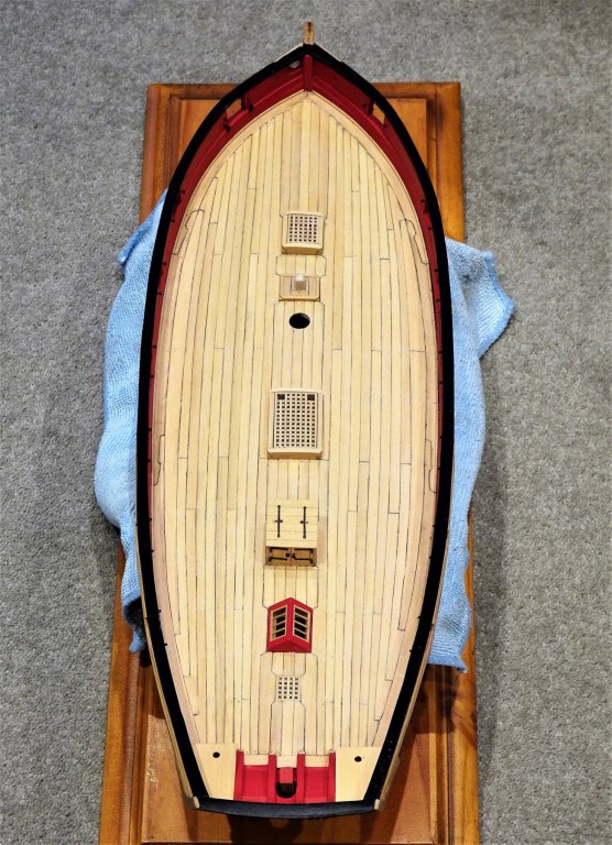
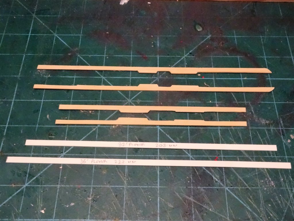
Post 51 Getting down to decking. I have glued into place the side tackle eyebolts for the guns, and ensured the ring bolts will slide easily into their holes later on. The deck beam positions have been marked on the false deck and the centre line fittings glued into place. I spent a fair amount of time staring at the deck plan and noting the reference details. It has been over seven years since I last planked a deck, one year into my previous Pegasus build, and I'm feeling somewhat ring rusty. The long planks outside of those between the centre line fittings range between 32 - 35' scale feet, and there is a four shift butt pattern.( 3 plank widths between butts across a beam.) The provided plan shows a joggled layout but Chuck has opted for a curved plank arrangement with hooded planks. I last used this arrangement on the Fo'csle deck of Pegasus, but they were much shorter lengths and far fewer in number. The process starts with the centre line planks and the narrative indicates that the first is placed right down the centre of the deck. The plan shows the centre two planks joining along the centre line. 4730 I played around with both arrangements to see which provided the better outcome when I came to fitting the adjacent full length planks either side. 4734 I eventually settled on the 'Chuck' arrangement but either way I would need to cut wider planks for the outside run to avoid slivers of planking alongside the centre line fittings. The section around the Bread room scuttle at the stern required cutting from some 3/64" x 9/32" strip. 4725 Tricky little patterns to cut but they do make for an interesting layout. 4727 With the planks in place the scuttle was sanded flush with the deck. 4731 4728 So another milestone reached which is also twelve months from the start of the build. I now need to do some working out of the remaining deck layout before I move on to complete the planking. B.E. 29/11/2018


.thumb.JPG.d94f4c0e8d266fbde3fa3dd6145bac50.JPG)
- 574 replies
-
- 27
-
-
- cheerful
- Syren Ship Model Company
- (and 1 more)
-
Clewline attachment to Topsail yard,HMS Cheerful
Blue Ensign replied to davyboy's topic in Masting, rigging and sails
Hi Dave, Steel makes reference to the standing end of the clew line being timber hitched to the yard and then stopd. B.E. -
With double skinned hulls you do get two bites of the cherry, and sanding and light filling will provide an excellent base for the second layer. For getting a little twist into planks such as where they run along into the stern post, I wet them and apply a hair dryer on full heat whilst I twist and hold with a pair of pliers. It really helps to take the spring out of planks and assist gluing. Nice start tho' James. B.E.
- 241 replies
-
- 1
-
-
- mermaid
- modellers shipyard
- (and 1 more)
-
Those 17th century Dutch ships make very attractive models. Fine work zappto, well done. B.E.
-
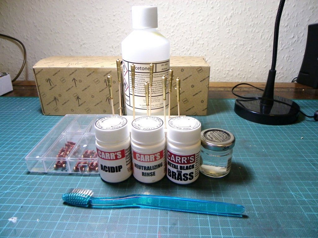
Thanks Wallace, This is my blackening kit, during the gun blackening process on my previous build. I use the metal black for brass diluted by around 20% As you will know the greatest part of success is having a chemically clean metal to work on. Regards, B.E.
- 574 replies
-
- 6
-
-
- cheerful
- Syren Ship Model Company
- (and 1 more)
-
Thanks Jason, Silver soldering is fairly simple at it's basic level such as closing rings or joining two bits of metal, all I have is a Microtorch butane burner and a couple of syringes of solder at different melt points. The beauty of silver solder is that it blackens along with the alloy. Cheers, B.E.
- 574 replies
-
- 1
-
-
- cheerful
- Syren Ship Model Company
- (and 1 more)


.JPG.3607cc2ec1f26b3467cb262933460aa6.JPG)


.JPG.005a4f29e71164c6be0cdd4f5e7b8262.JPG)
.JPG.111a0d51bbdc0f091fc735aa87f47bcb.JPG)
.JPG.5cd965414950ee13a65bc7042c5a5953.JPG)


.JPG.d8610d44871bb3f780f2f138a545df29.JPG)
