HOLIDAY DONATION DRIVE - SUPPORT MSW - DO YOUR PART TO KEEP THIS GREAT FORUM GOING! (Only 13 donations so far - C'mon guys!)
×
.JPG.ca33079f5815b861e67b9c2cccd37982.JPG)

Blue Ensign
-
Posts
4,564 -
Joined
-
Last visited
Content Type
Profiles
Forums
Gallery
Events
Everything posted by Blue Ensign
-
I am also surprised that the academics seemed to think it a revelation find people of North African descent in England in Tudor times. It is interesting to try and establish the origins of the crew, but I did find the presentation overdone and somewhat irritating. Surely they were not unaware that there was sea trade between Europe and the Mediterranean which would always lead to a degree of mingling certainly in coastal areas, and of course seafarers of North Africa generally known as the Barbary pirates, were very active in European waters from the 16th century to feed the North African slave trade, something academics tend to shy away from in present times. B.E.
-
 Beautifully done Ian, a fine build and great photo's, I would be more than happy to give your Cheerful house room. 🙂 B.E.
- 51 replies
-
- 2
-

-
- cheerful
- Syren Ship Model Company
- (and 1 more)
-
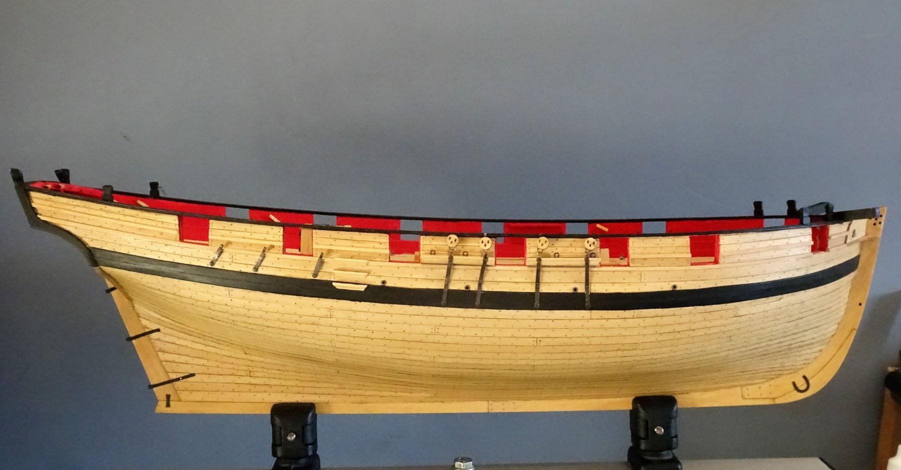
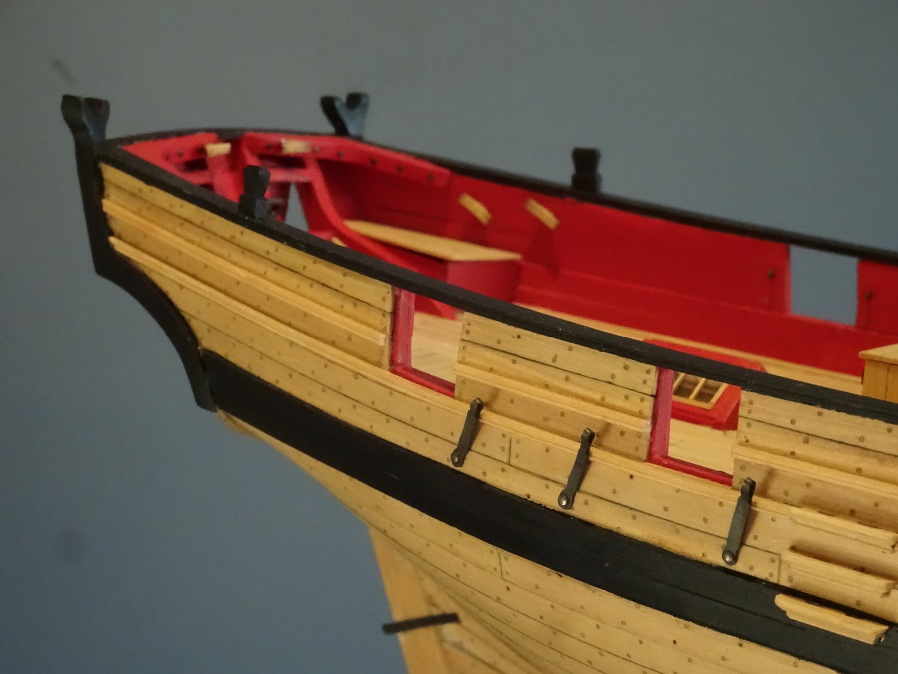
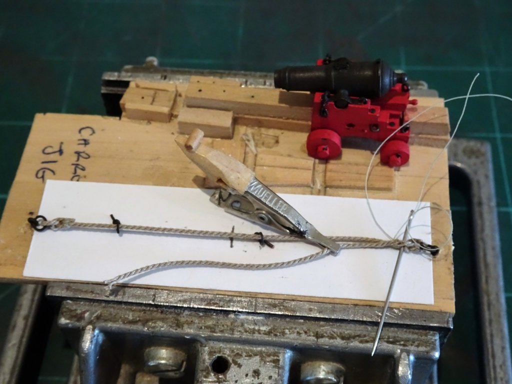
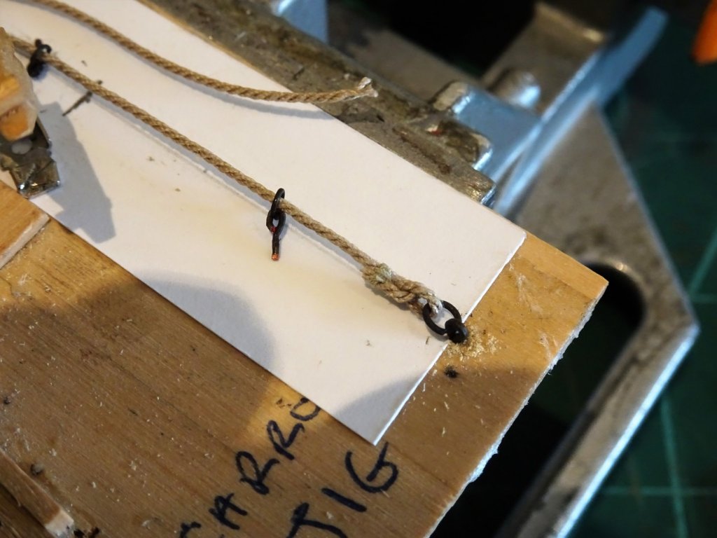
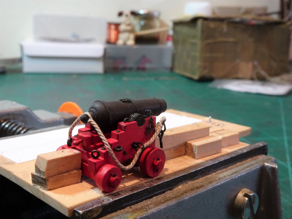
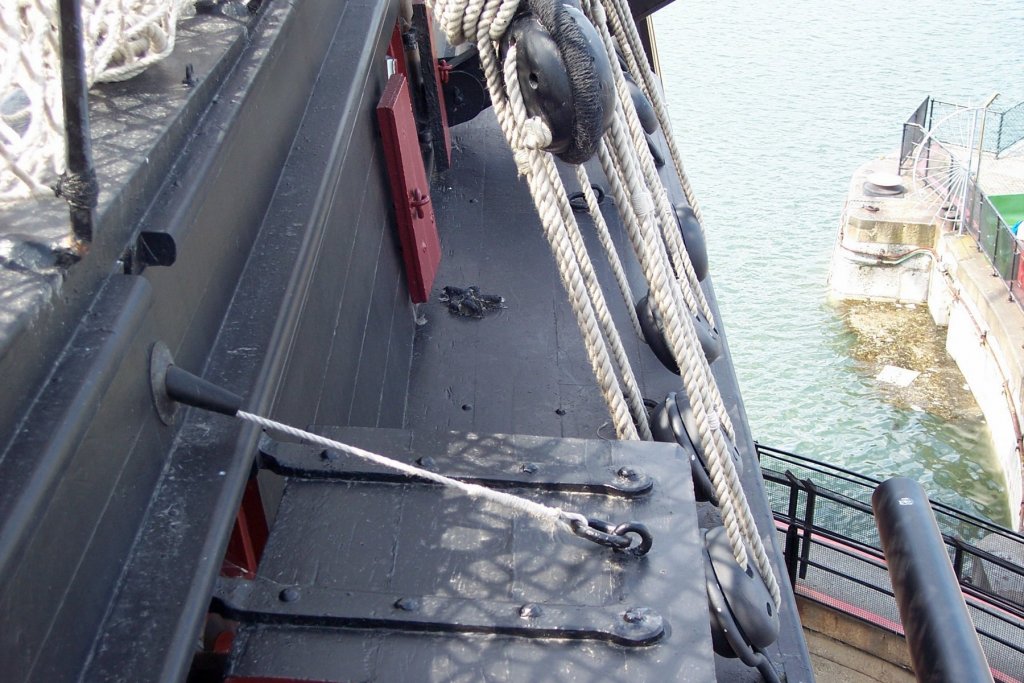
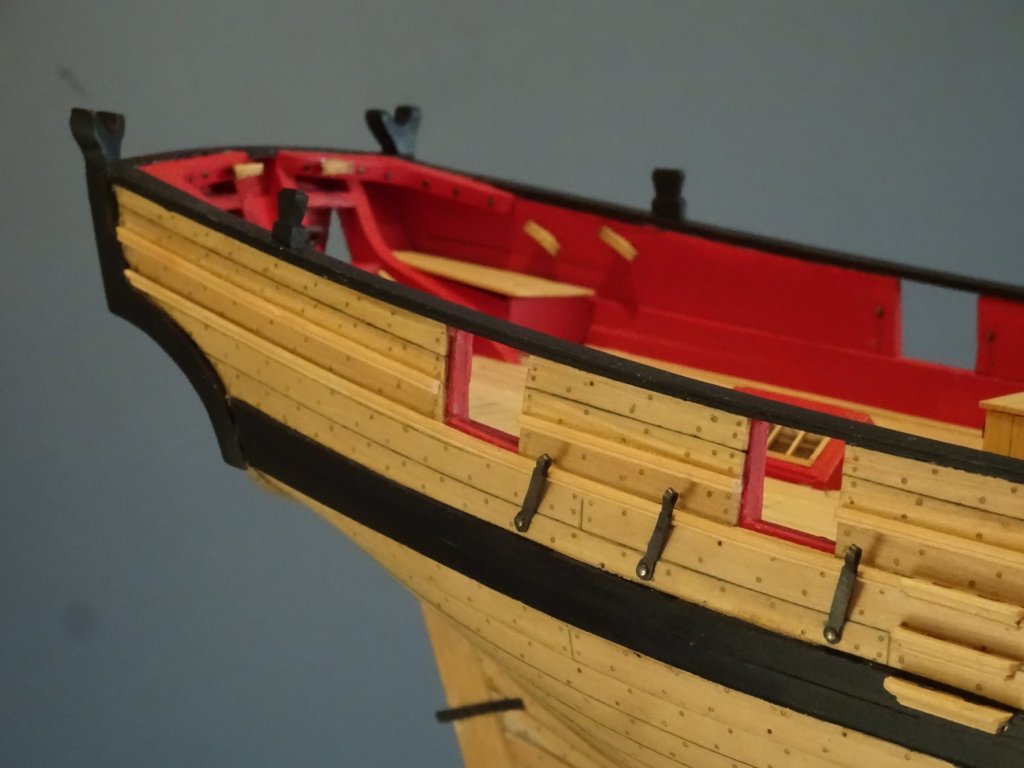
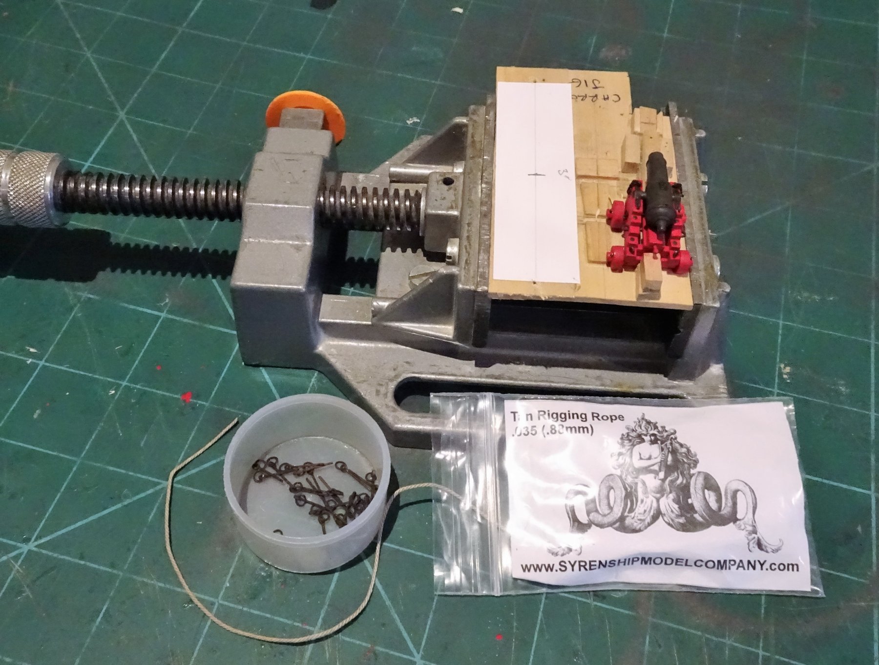
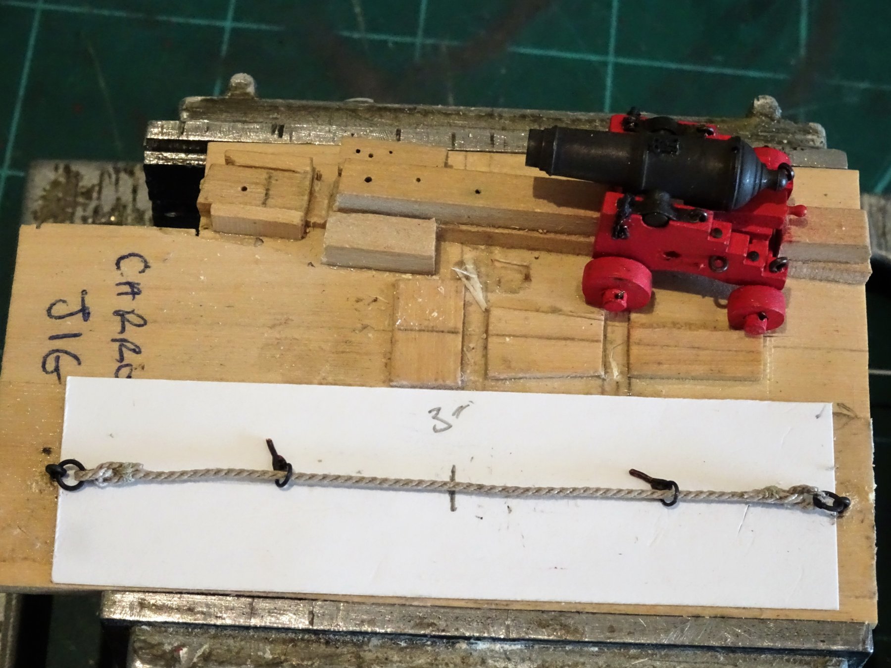
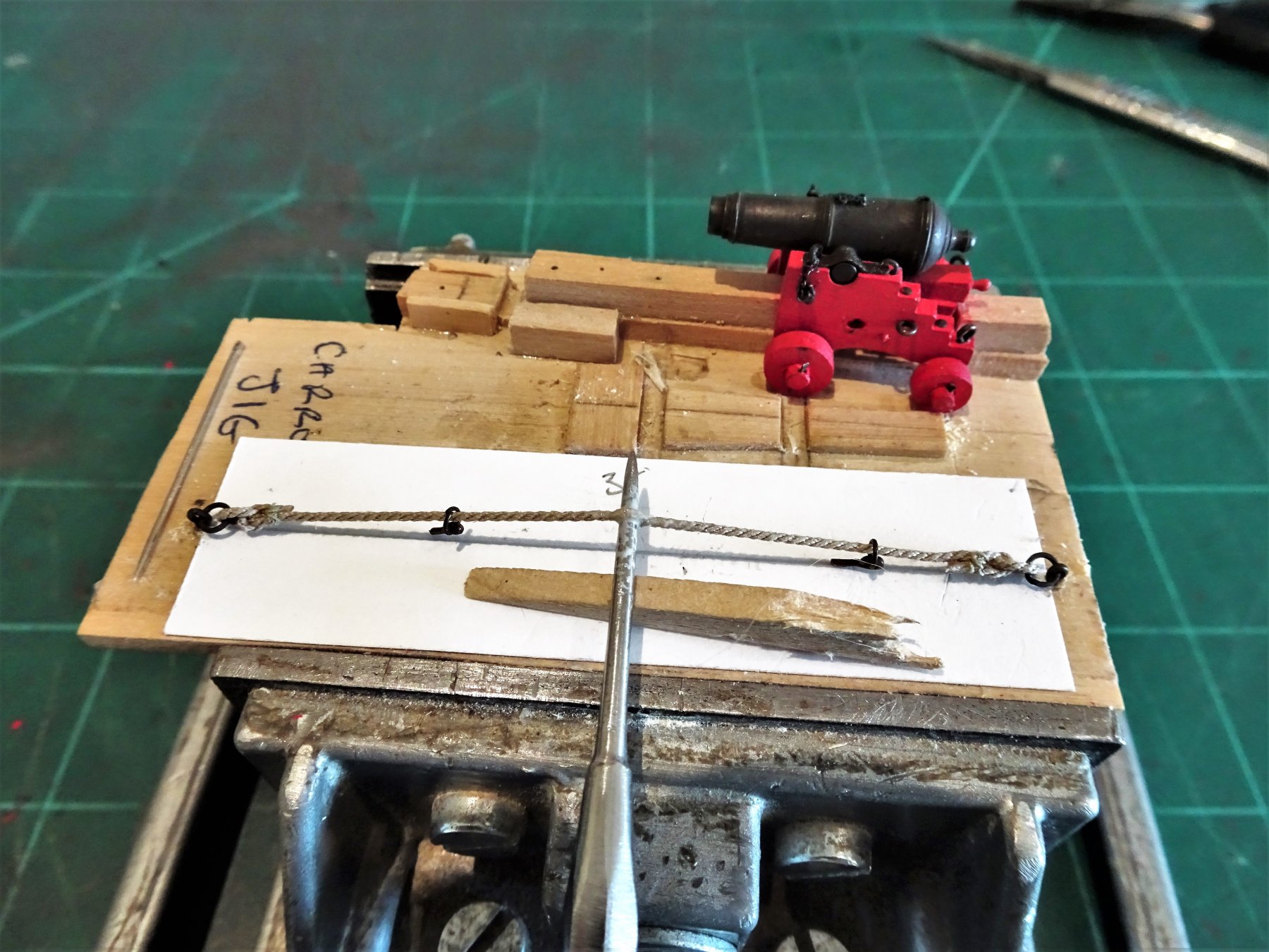
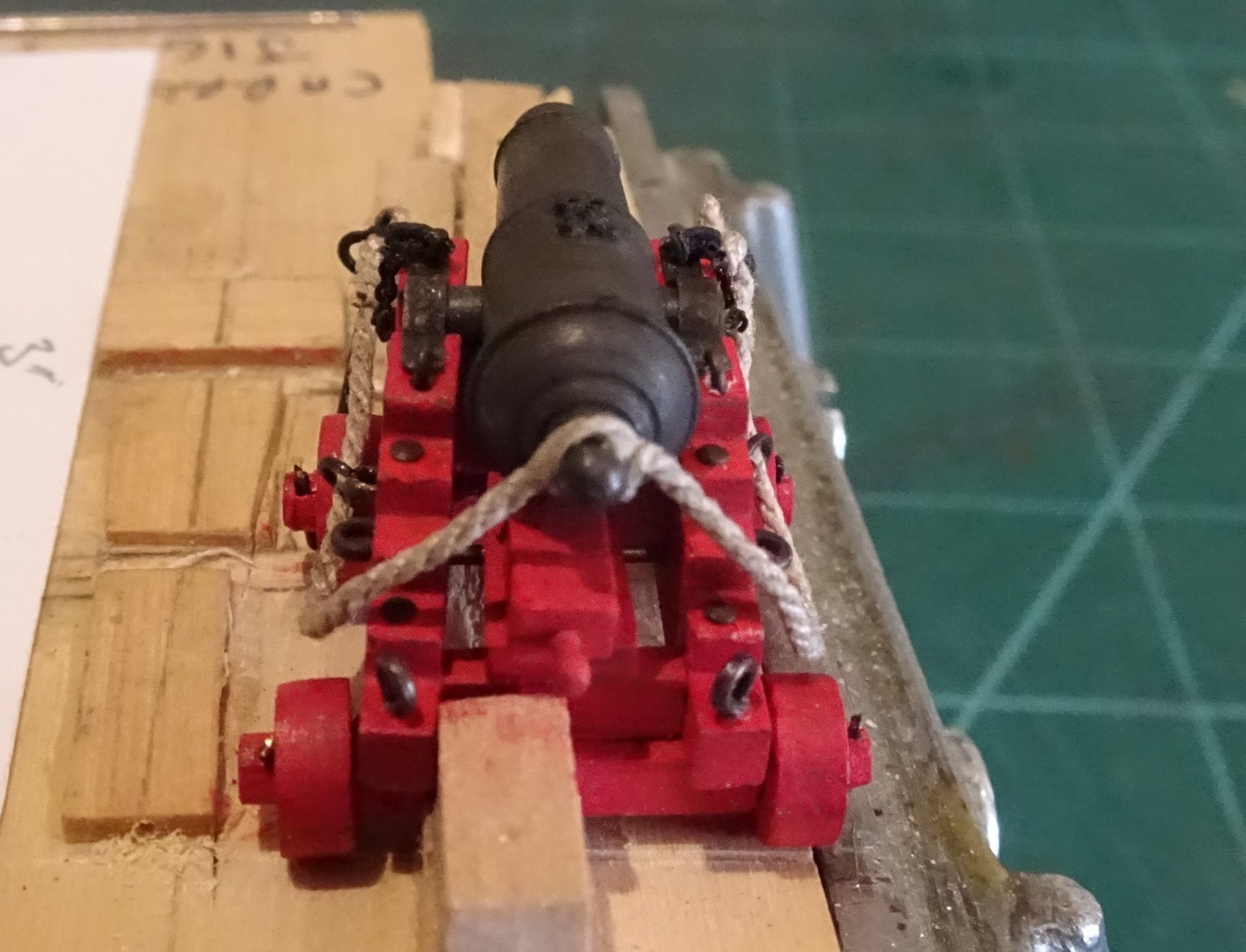
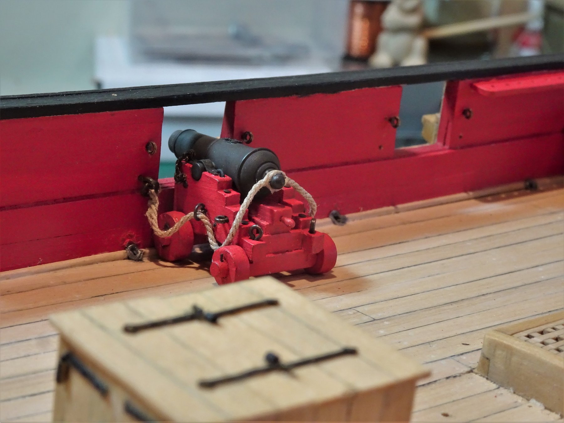
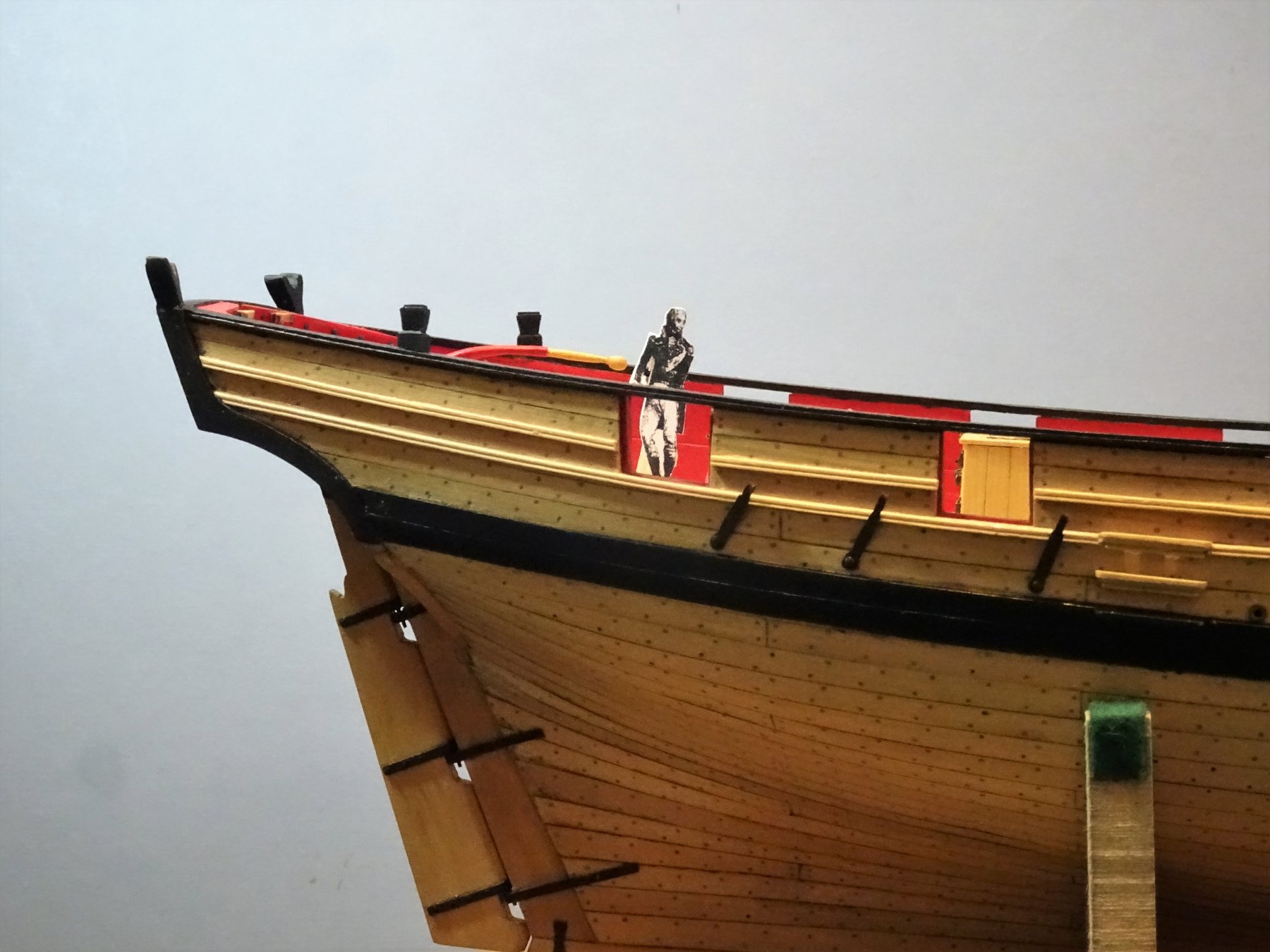
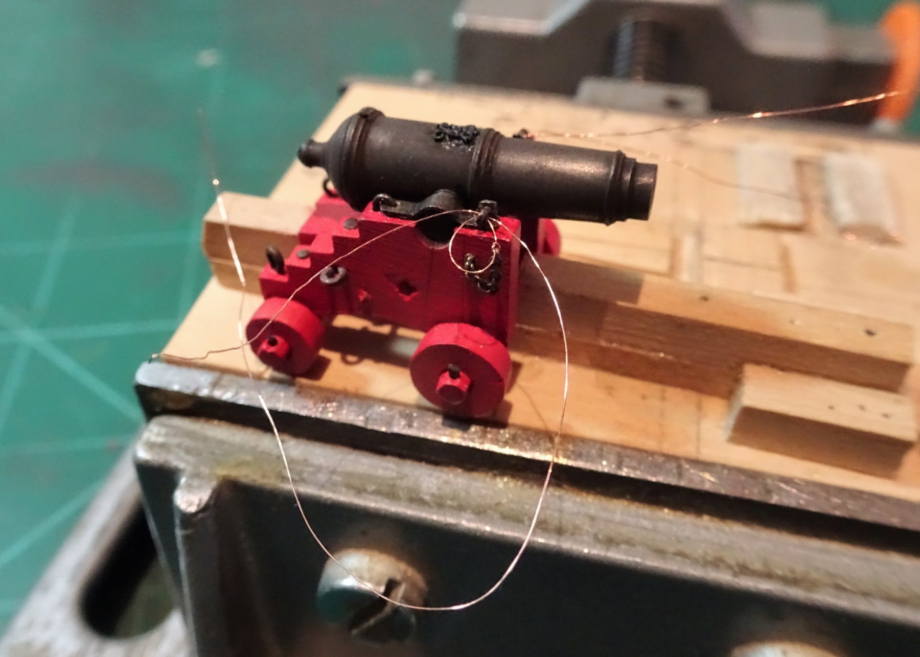
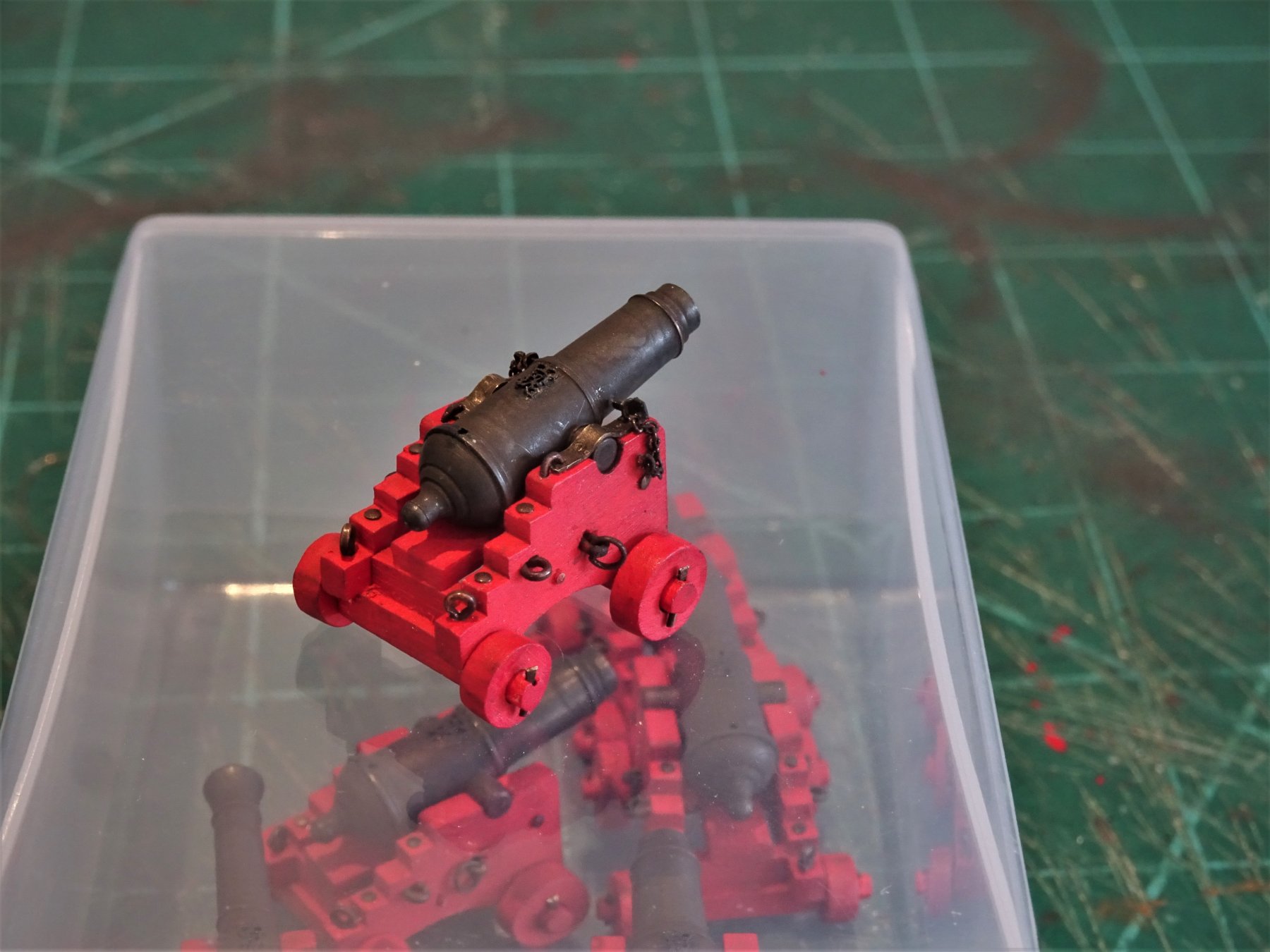
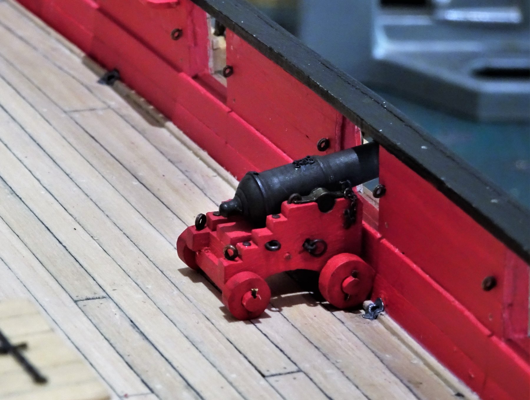
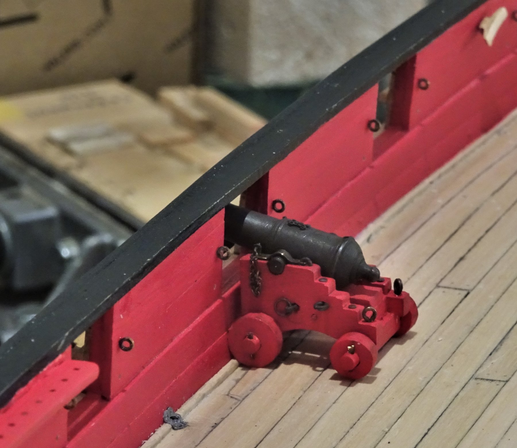
Thank you Dave, OC, and Thomas. @ Dave, I'm not thinking of fitting a spectacle plate, but that doesn't mean to say rudder tackles didn't feature on cutters of Cheerful's size. Loss of a rudder was a serious matter on any vessel, and Cheerful's rudder was not a lightweight item being in the order of 18' long x 3' maximum width. I've not seen such tackle represented on models of this type but I don't think anyone could gainsay you if you decided to add a ring to secure the rudder. Post 77 Rigging the guns Starting with the Breeching lines. 7201 I am using Chuck's syren line (.035"/.88mm ø Tan line) This equates to 5" circ line, about right for the ordnance. To start the process my gun jig modified to assist with the breech rope fitting is brought back into use. The first decision is how to seize the breeching line to the bulwark ring. 7227 7222 To apply the seizing I am using 0.1mm Morope polyester line, a needle proves very useful in this task. 7224 One of my concerns is not to have the bulwark breech seizing look too bulky. I trialled a couple of seizing arrangements but finally settled on a simple seizing which was the best to my eye at this scale. 7229 Forming the eye to fit around the the cascobal. 7246 7245 Pushing the loop over the cascobal has to be done with great care to avoid marking the blackening. 7308 I use rounded wooden toothpicks for this purpose. 7327 Trial fitting on deck. 7317 Nothing fixed at this stage, but one thing is clear, the gun needs to be secured in position in order to arrange the breeching line in the best fashion. I'll ponder on this whilst I complete the breeching lines, but I am leaning towards a spot of pva on the wheels to hold the guns in place. B.E. 22/03/2019


.thumb.JPG.d43701b79ba5e34376ef8474bc5bc823.JPG)

- 574 replies
-
- 24
-
-
- cheerful
- Syren Ship Model Company
- (and 1 more)
-
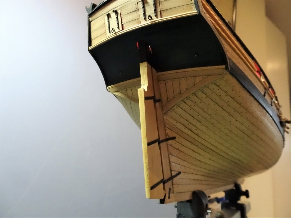
Hi Tony, I don't have any definitive information on rudder coats for open sterned cutters such as Cheerful. My reasoning is purely that she is single planked at the transom where the rudder head enters the deck and without the small deck that sometimes covers the rudder head. The cutter Alert has such a platform deck over the housing for the rudder head, but Peter Goodwin neither refers to or indicates the use a rudder coat either in words or drawings. Where such a deck is enclosed at the front with perhaps compartments for storage it would make sense to reduce if not eliminate entry of water. However, the contemporary models of Surly and Cheerful included by Chuck as part of his reference work also don't show this feature but that in itself is neither here nor there, rudder coats rarely feature on contemporary models. I think if I was building a model cutter with an enclosed rudder head I would probably fit a rudder coat, but simply because that makes sense to me. I did in fact fit a rudder coat to my model of Pickle including a cover inboard, and she is an open decked vessel, but it seemed appropriate at the time. Thank you for the appreciation of my rudder, I hadn't given any thought to serving the handle with fine line, but I think I will leave it with just a plain finish. Cheers, B.E.
- 574 replies
-
- 3
-
-
- cheerful
- Syren Ship Model Company
- (and 1 more)
-
Liking your progress Rob, I think you are right to feel satisfied with the results. 👍 B.E.
-
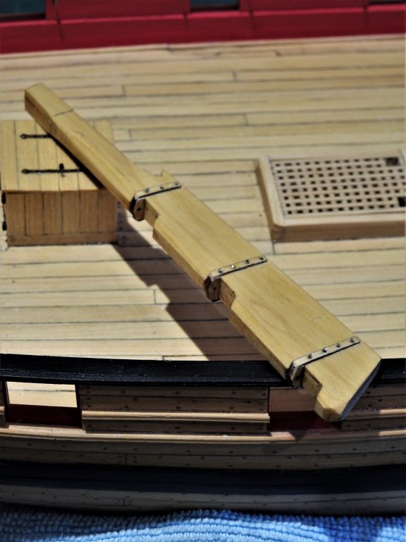
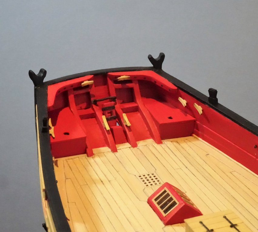
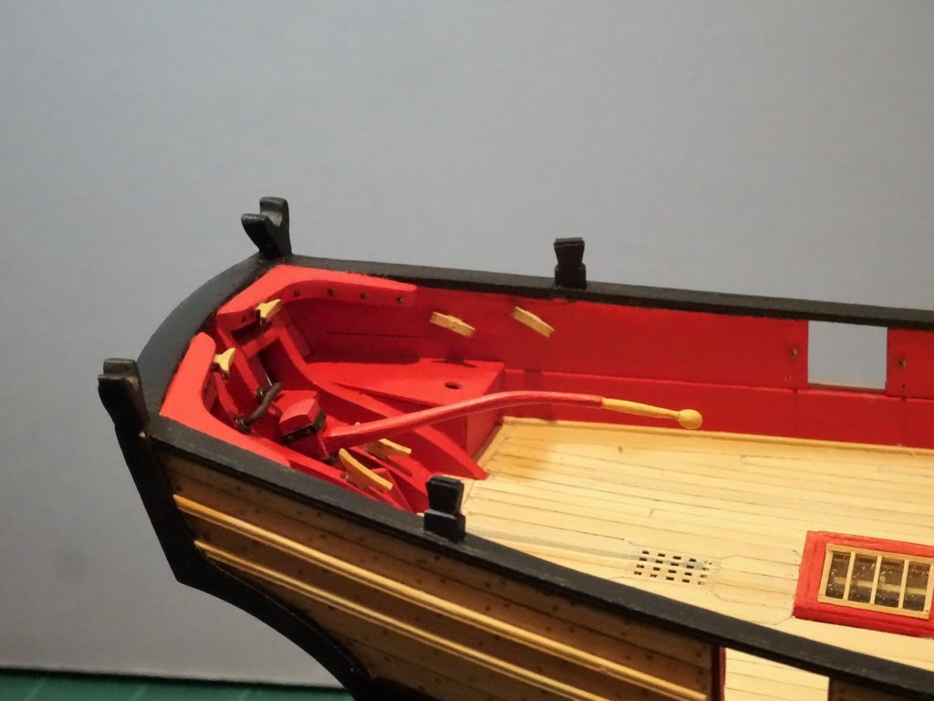
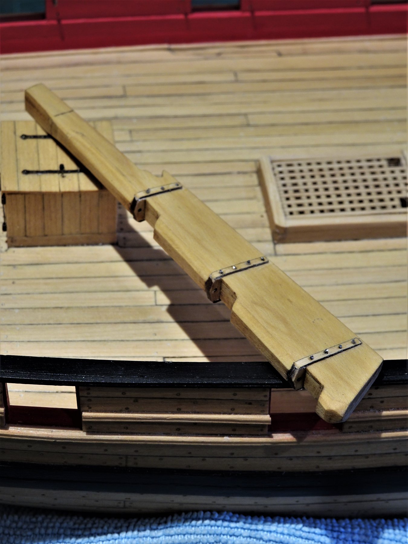
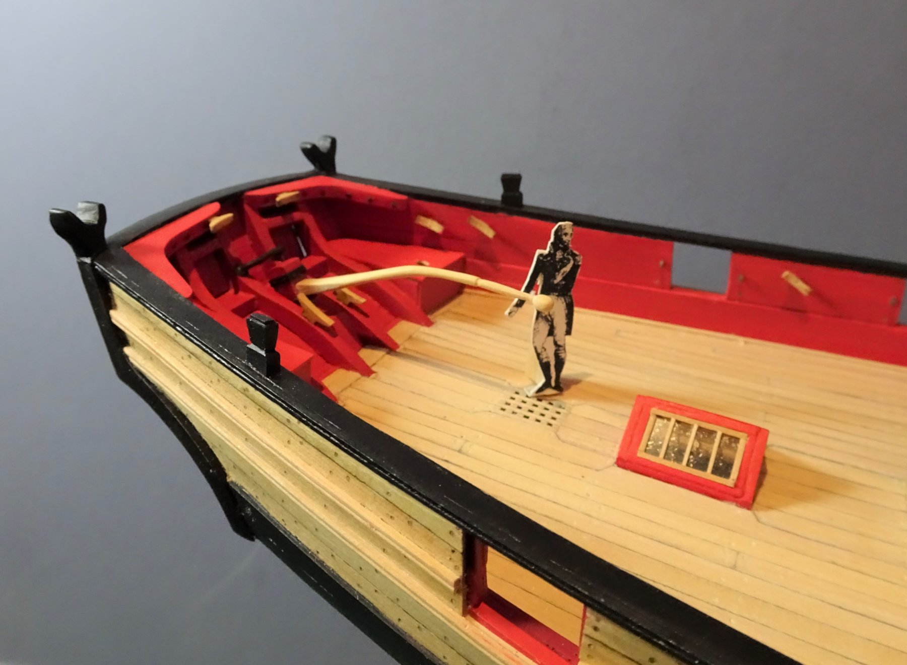
Cheers Michael, and thanks for the reminder about those teenytiny lines and knots.😉 Post 76 Completing the rudder I had completed the rudder and its ironwork earlier in the build but now I turn to adding the tiller. 4904 3017(1) 7156 I may be wrong but I don't think a rudder coat is necessary given that the rudder head doesn't pass betwixt decks. Onto the Tiller Chuck had suggested cutting the tiller from some 1/8th Boxwood sheet and I followed his example. There followed a period of shaping using a scalpel blade, files and sandpaper. I did the whole tiller from one piece including the ball on the end. 7185 The rudder was secured on the mill to cut the mortise for the tiller heel. The iron bands were added around the rudder head using Chuck's Laserboard fittings, the bolt heads represented by mini pva blobs allowed to dry before painting. 7151 The tiller is not glued into place, it is held by a snug fit of the tenon in the rudder mortise. In fitting the tiller I took care to ensure that the underside height at the forward end was 22mm (41" above deck.) Don't want the helmsman to be on tiptoes to steer the ship. Once again I found myself indecisive when it came to the decoration of the tiller; all natural, paint, part paint/natural, bloody decisions. 7189 In the end I decided, at least for the present, to paint the tiller arm red but varnish the handle section. 7198 7196 Back to gun rigging. B.E. 18/03/2019


.thumb.JPG.8d6fb8ff70cc4904dd32855105b1e301.JPG)
- 574 replies
-
- 27
-
-
- cheerful
- Syren Ship Model Company
- (and 1 more)
-
Great detail shots there Rusty👍 Clearly show how good your work is. B.E.
-
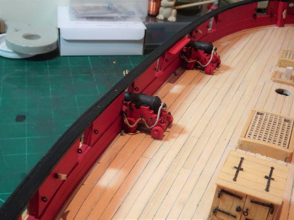
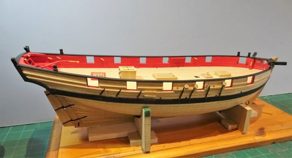
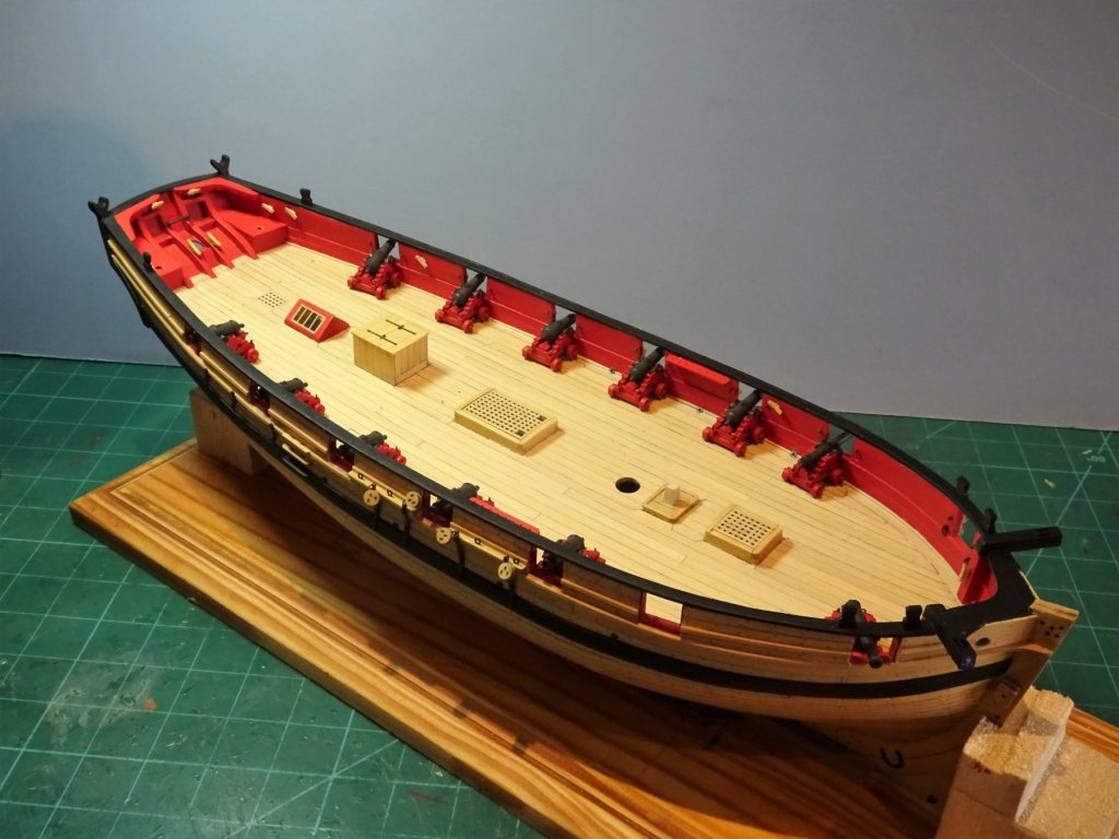
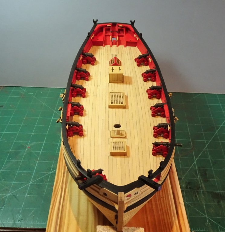
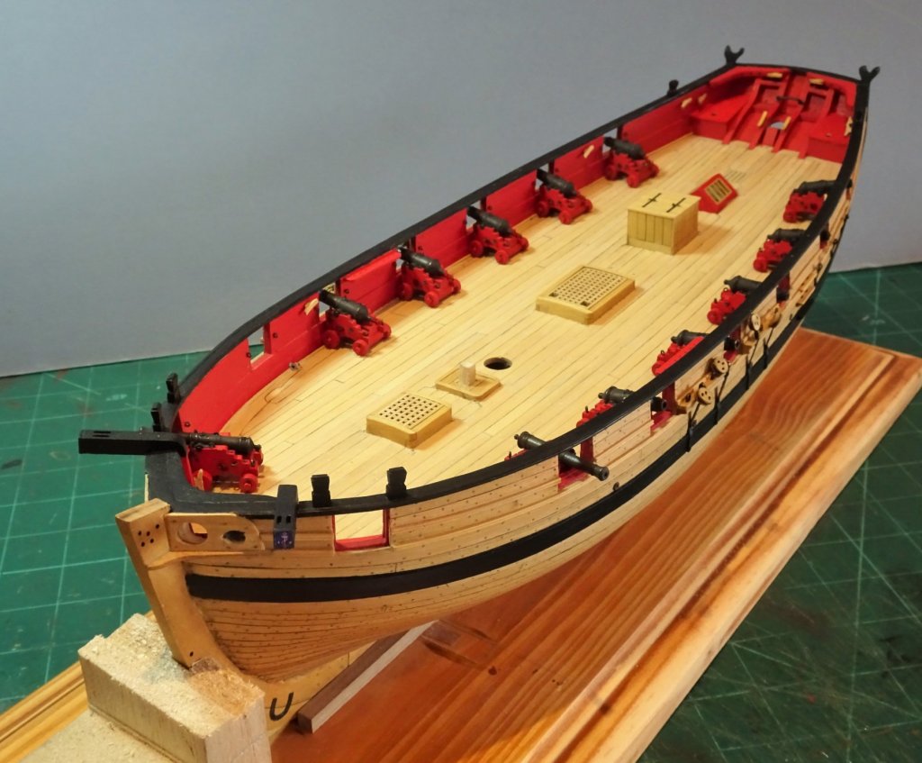
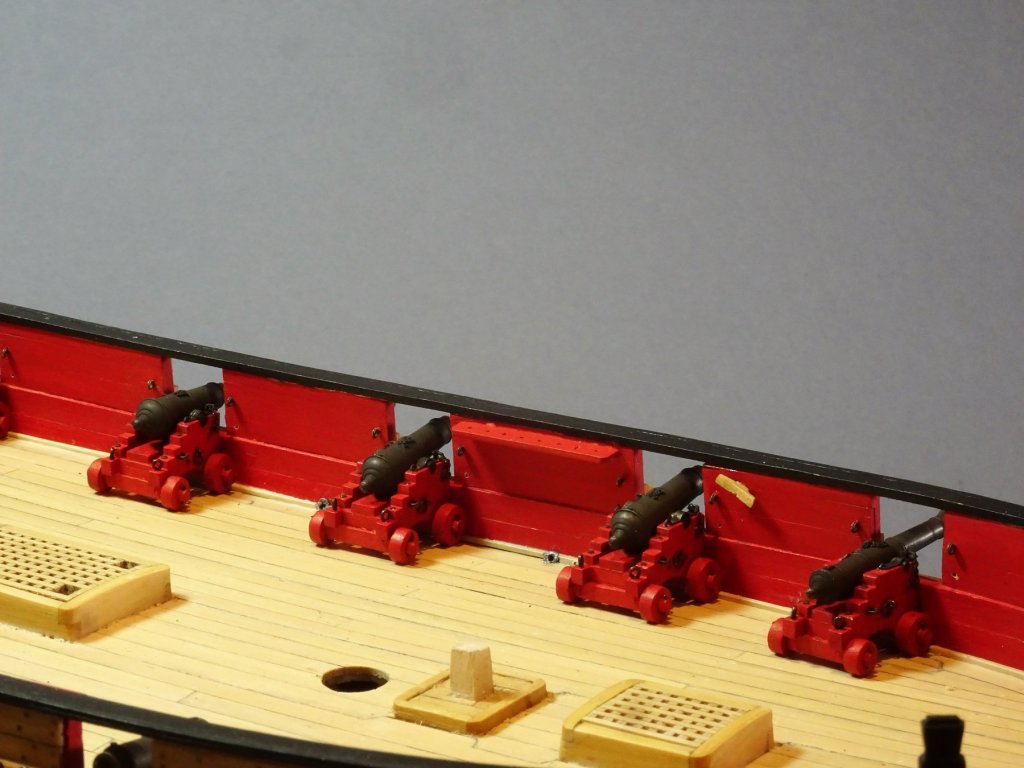
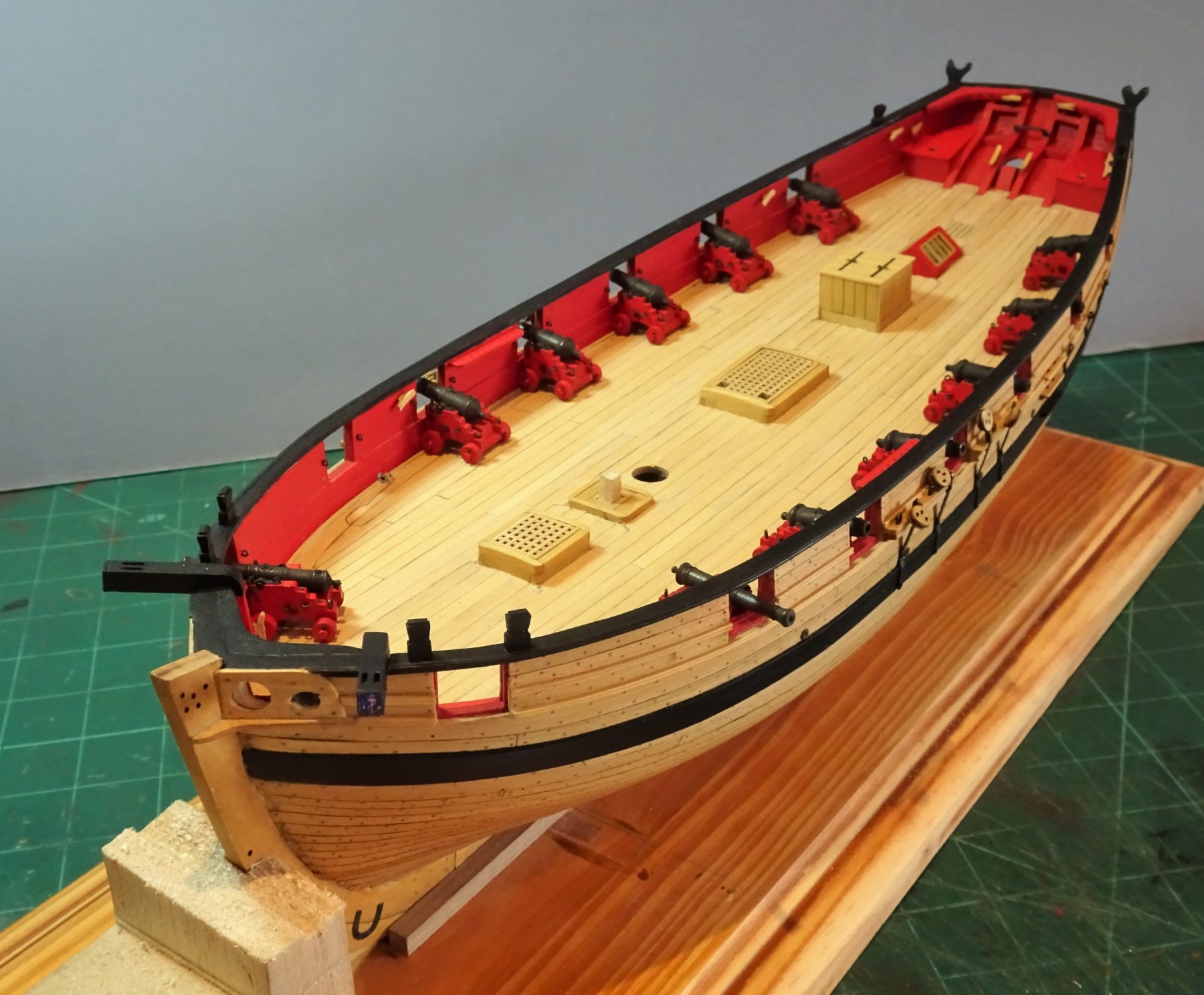
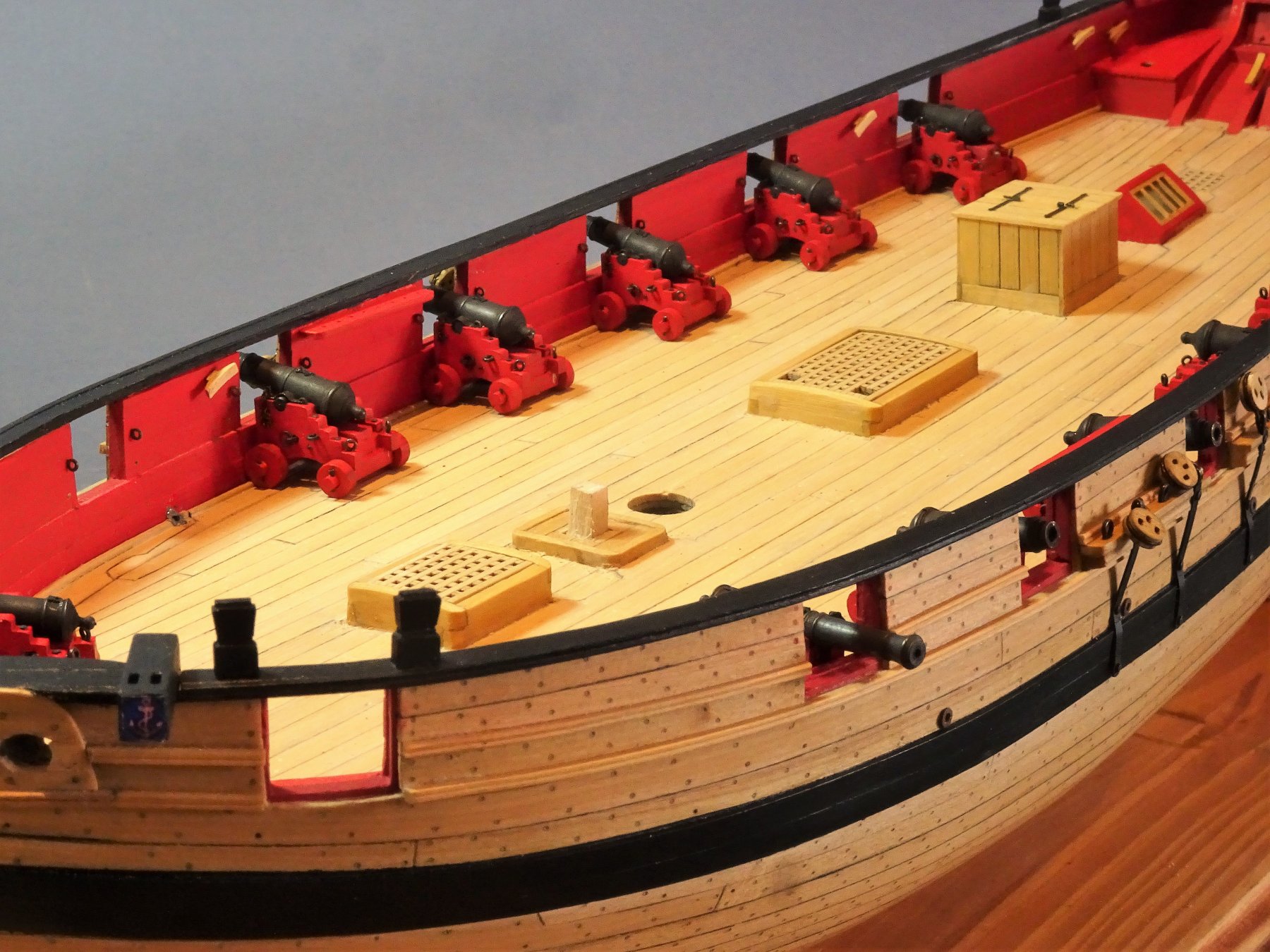
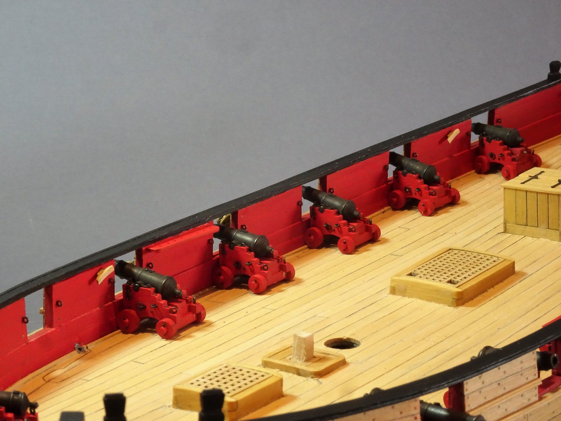
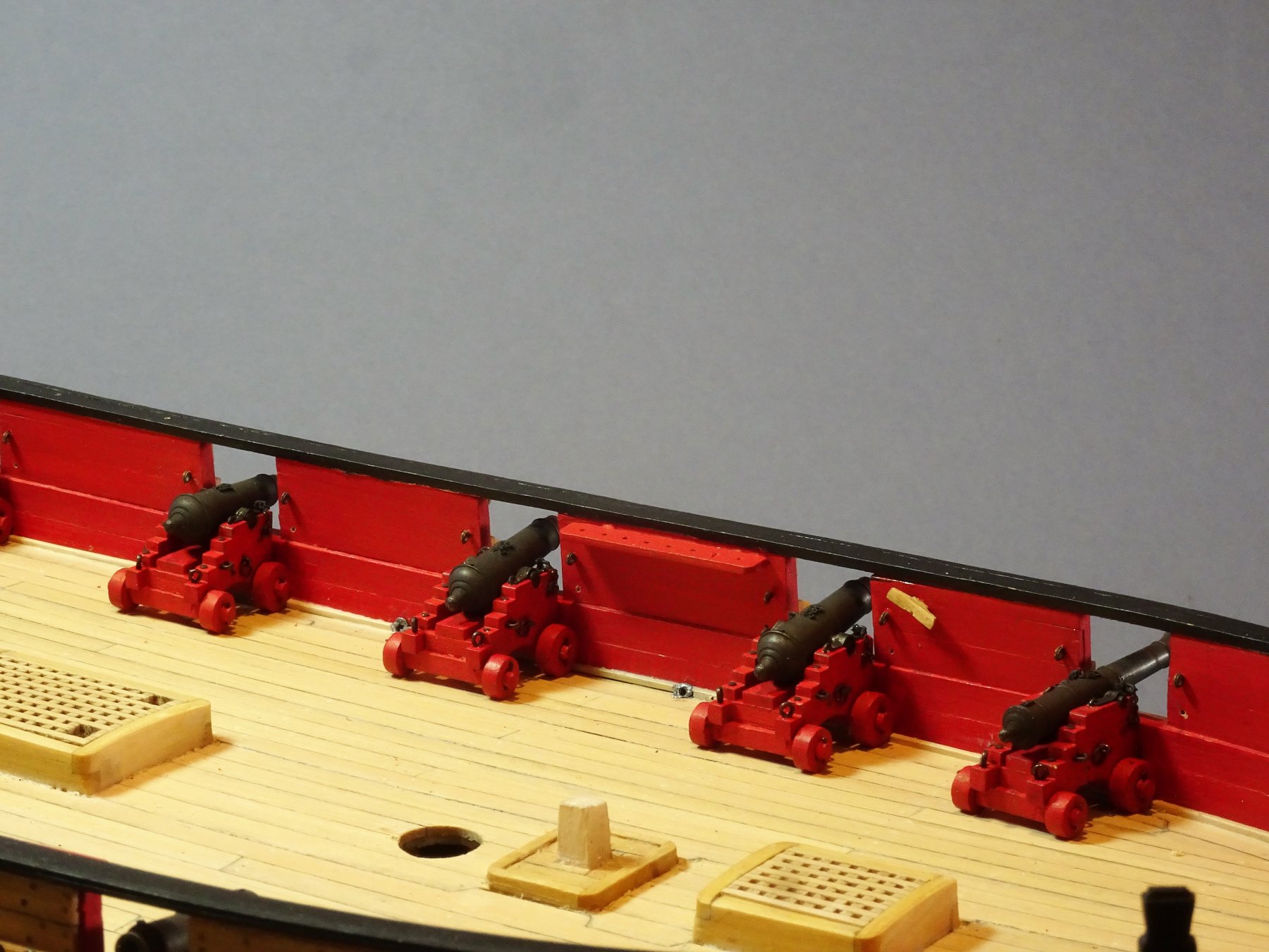
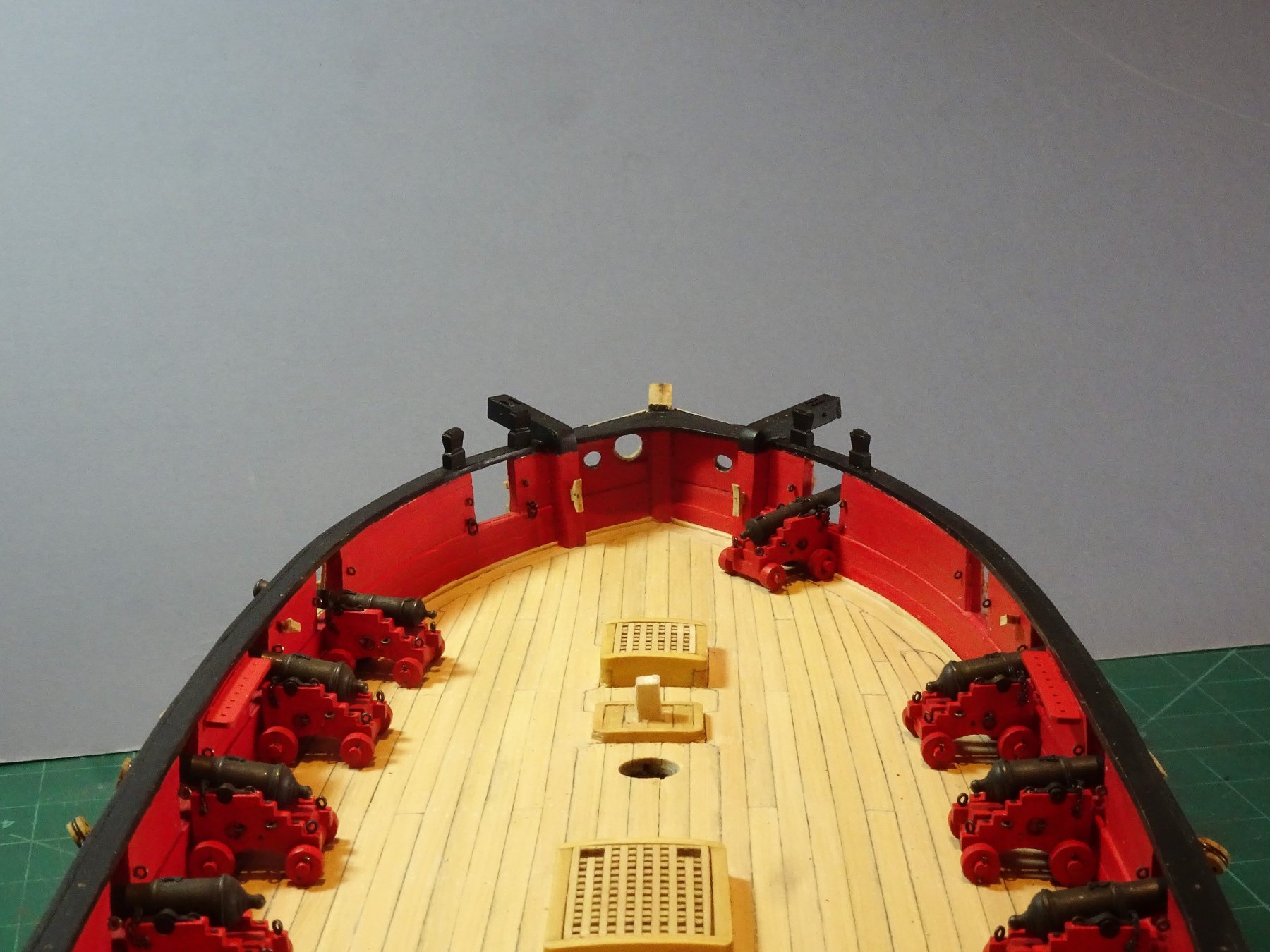
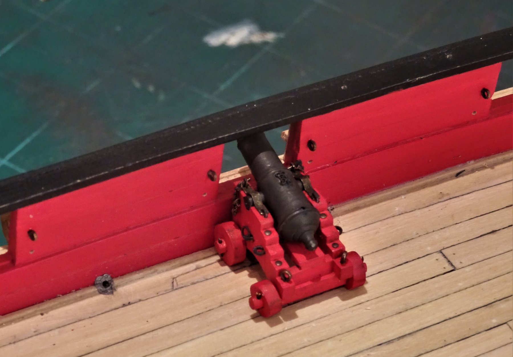
Cheers guys for the appreciation and 'likes' 🙂 Post 75 Ordnance all in order The fiddly fittings are all completed, not the end of the process as the quoins have to be glued in position and then there's the tackle rigging, but a relief nonetheless. 7098 7113 For the first time the full complement in place on Cheerful. 7114 7116 7111 7107 7105 7104 Before I return the task of tackle rigging I will have a change of scene and complete the rudder and make the tiller. B.E. 15/03/2019


- 574 replies
-
- 28
-
-
- cheerful
- Syren Ship Model Company
- (and 1 more)
-
Bellona is a fine subject, the classic British 74. I also like subjects with plenty of reference history, in the case of Bellona there is the NMM model and the Anatomy of the ship book by Brian Lavery. Personally I am waiting for your cutter Alert, that too has an Anatomy series book by Peter Goodwin. Every success to you Chris. B.E.
-
Feel free Kevin, glad it helped. B.E.
-
Hi Kevin, Here is a shot of how the line is currently set up on Victory. (or was a few years ago) It passes thro' the Mizen channels and is secured with a knot. I recall that the guides at the time were unable to understand what I was talking about and let me get on the Poop to show them. Doesn't necessarily help matters but perhaps when required lines were attached held by the knot. . Regards, B.E.
-
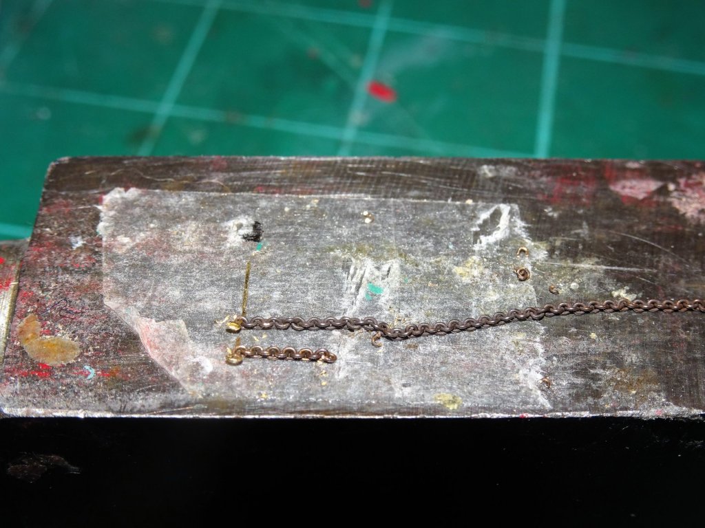
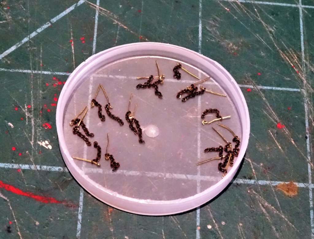
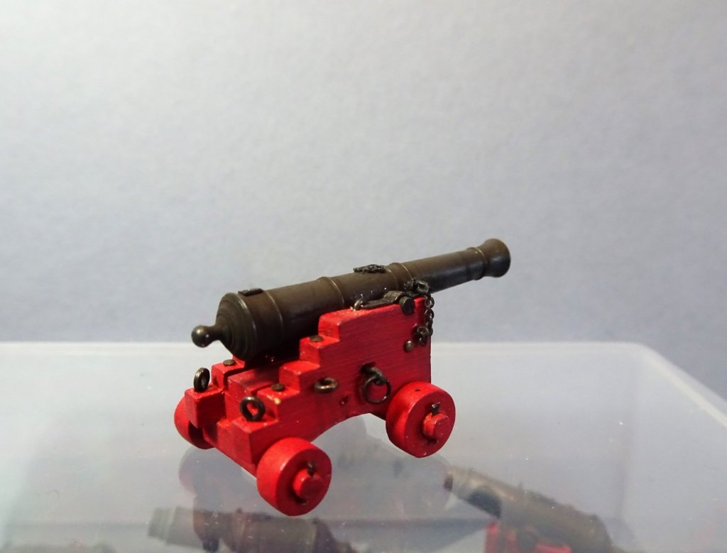
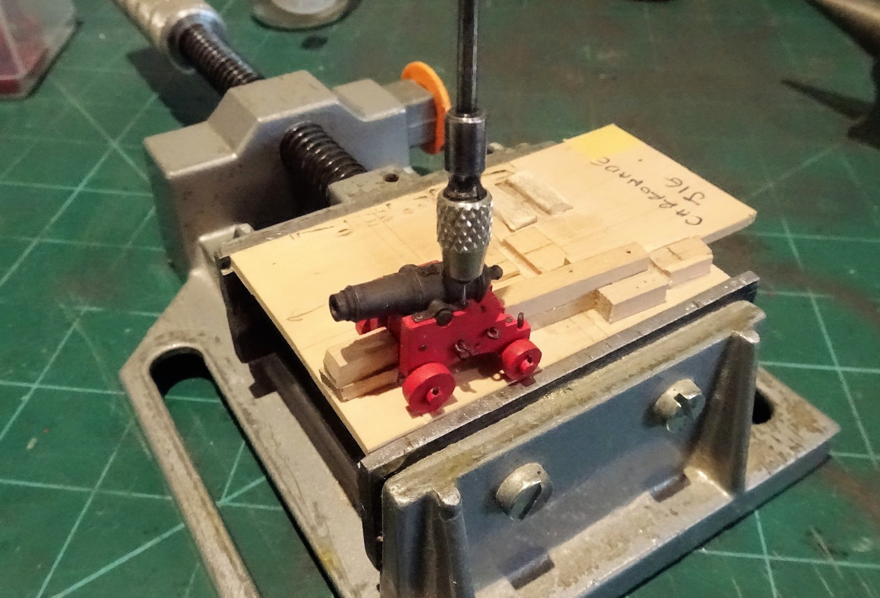
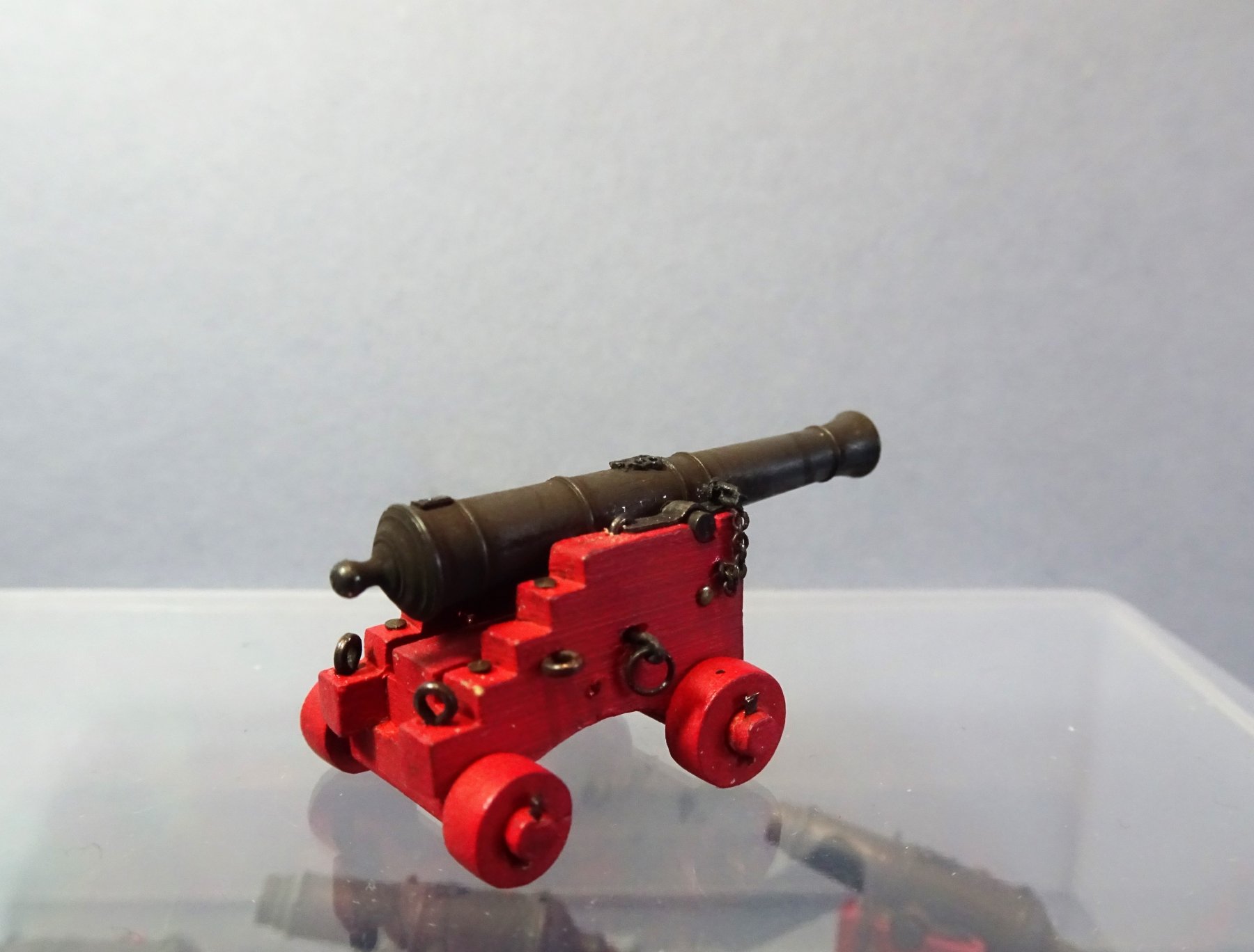
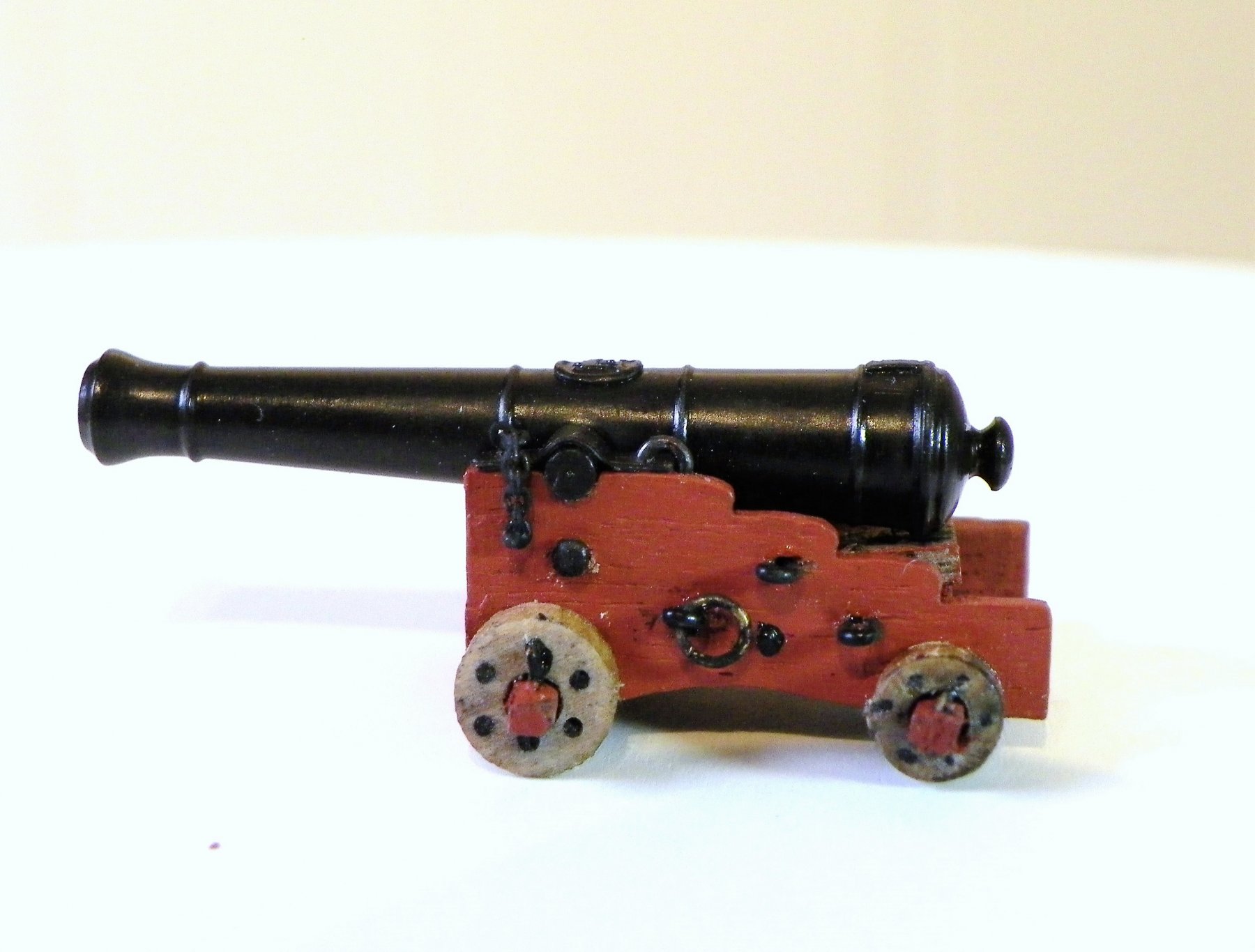
Cheers Martin, keep at it I have🙂 Post 74 Continuing adventures with guns. So with renewed resolve I start to rethink my approach to fitting out these chunky little carronades. Method is everything to avoid frustration which ultimately results in giving up. Getting into a it'll be done when it's done mind set also helps. Most of the problems in adding additional features revolve around holding the parts and in my particular case tired old eyes, and to think I went larger scale to make things easier for myself. 6451 This time I start by threading the chain onto 0.3mm brass etched eyebolts and once I got the required length used one as a template to make the others. 6359 The finished chain length is 5mm. The eyebolt rings were cut and closed to reduce them in size but still secure the chain. I fashioned the keys and bolt but at a slightly smaller size. I think it was this feature that I was least happy with first time around. 6367 I also decided to pre-glue the keys into the bolt before fixing because once in place they are a fixed point to attach the chain. 6636 During the operations a jig to hold the gun helps to avoid handing. 6889 The chain is attached to the key using fine wire. 7035(2) Sealed with a spot of ca, a paint touch up, and the jobs complete. 7045(2) 7043(2) 7040(2) 6894 Making the capsquares for the long guns was somewhat trickier than for the carronades. There is little room at the forward end to drill and fit the retaining bolt and key. Now all this is a lot of extra work for a small feature, but we are all prisoners of our foibles, and this is yet another one of mine.🙄 Still I am happy with the result and there are only four guns left to do which I will complete at a leisurely pace over the course of next week. B.E. 10/03/2019


.thumb.JPG.aa22d0b2aeb1987bd119c76437bb4dc9.JPG)
.thumb.JPG.3c0de1f9daceb66ec63c16828b5765cb.JPG)
.thumb.JPG.b638fffc6efc3c1d371c1a96d178e1b4.JPG)
.thumb.JPG.b8d737dde541104f850a358bbf5e3595.JPG)
- 574 replies
-
- 23
-
-
- cheerful
- Syren Ship Model Company
- (and 1 more)
-
Nice work on the skylight and Binnacle Caroline, tricky little beasts to make aren't they. On the question of gun stowage my understanding is that lashing alongside was mostly used where space was at a premium such as in cabins.This was the case on Victory in the Masters cabin on the Quarterdeck. It is your option of course but I doubt this arrangement was used on a sloop such as Pegasus on the open gundeck with no port covers. If I was motivated to demonstrate such an arrangement I think I would restrict it to one gun only each side, but the aesthetics also need to be considered in terms of the model. Regards, B.E.
- 161 replies
-
- 3
-
-
- pegasus
- victory models
- (and 1 more)
-
Beautiful shots of a beautiful build, well done Rusty, a great reference work to follow. B.E.
-
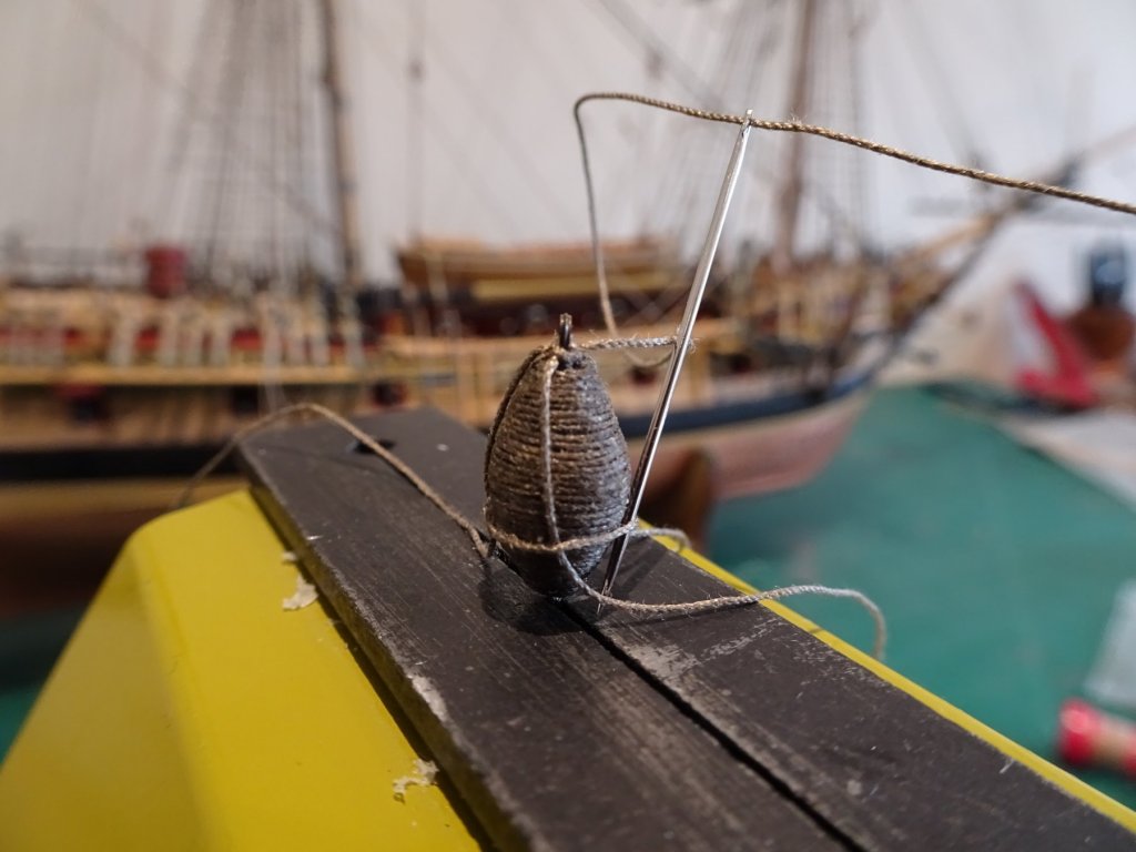
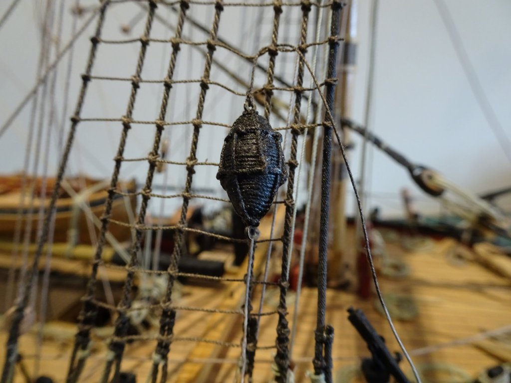
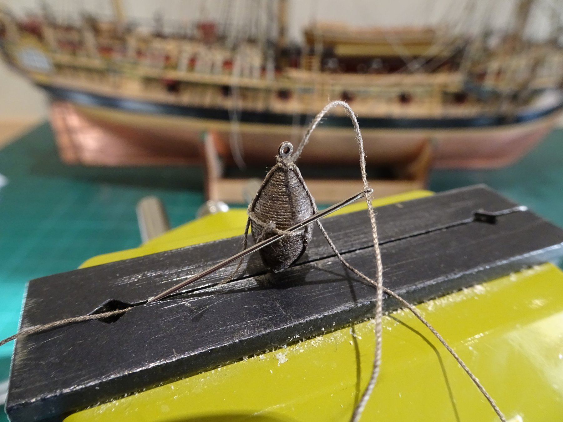
So true Wallace, satisfaction is the key, do it to a level that pleases me - satisfaction. Don't do it, a constant niggle that I failed and should have tried harder. @ Grant - Thanks Grant , I suspect you're right.😃 @ Dave, glad the blocks worked out; for the slings I fitted the horizontal bands and then used a needle to thread the verticals beneath the horizontals, and seized them with a false splice. I believe the buoys were tarred. I dipped mine in some Dark Jacobean wood stain. Not sure that wire will give the best appearance on the buoys. 4355 4363 4357. Hope these pics may help. Cheers Guys, B.,E.

- 574 replies
-
- 13
-
-
- cheerful
- Syren Ship Model Company
- (and 1 more)
-
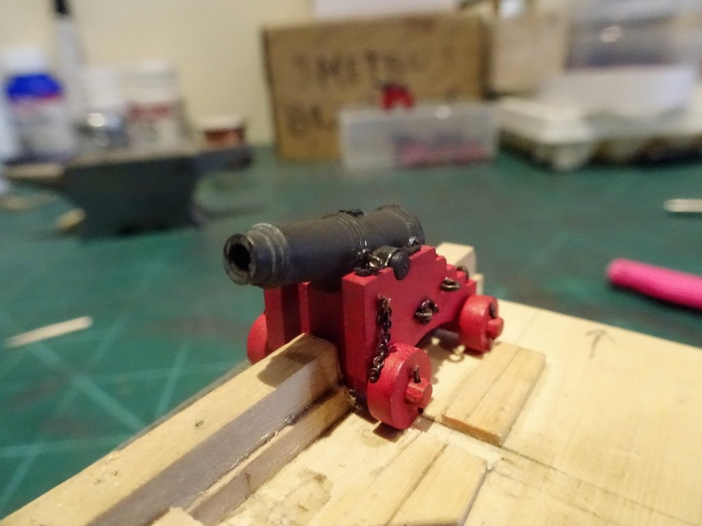
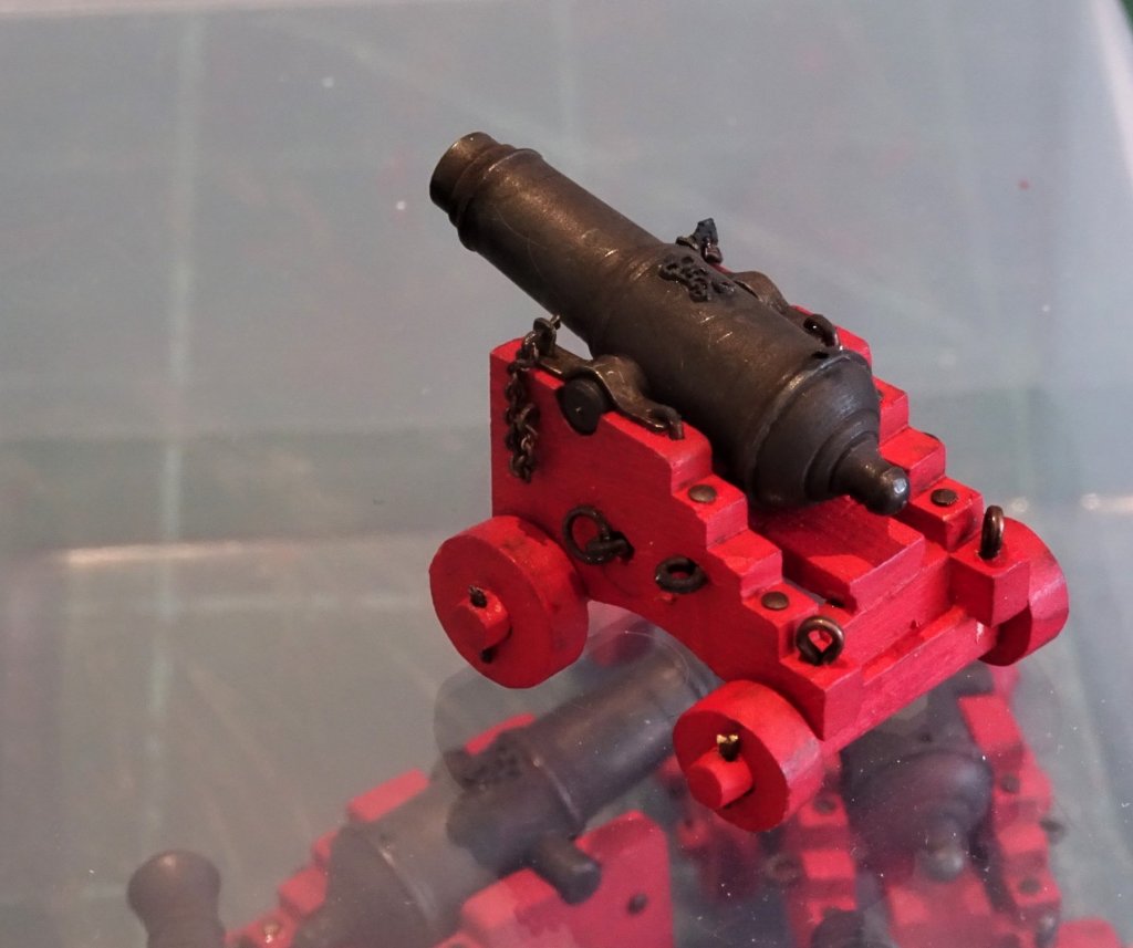
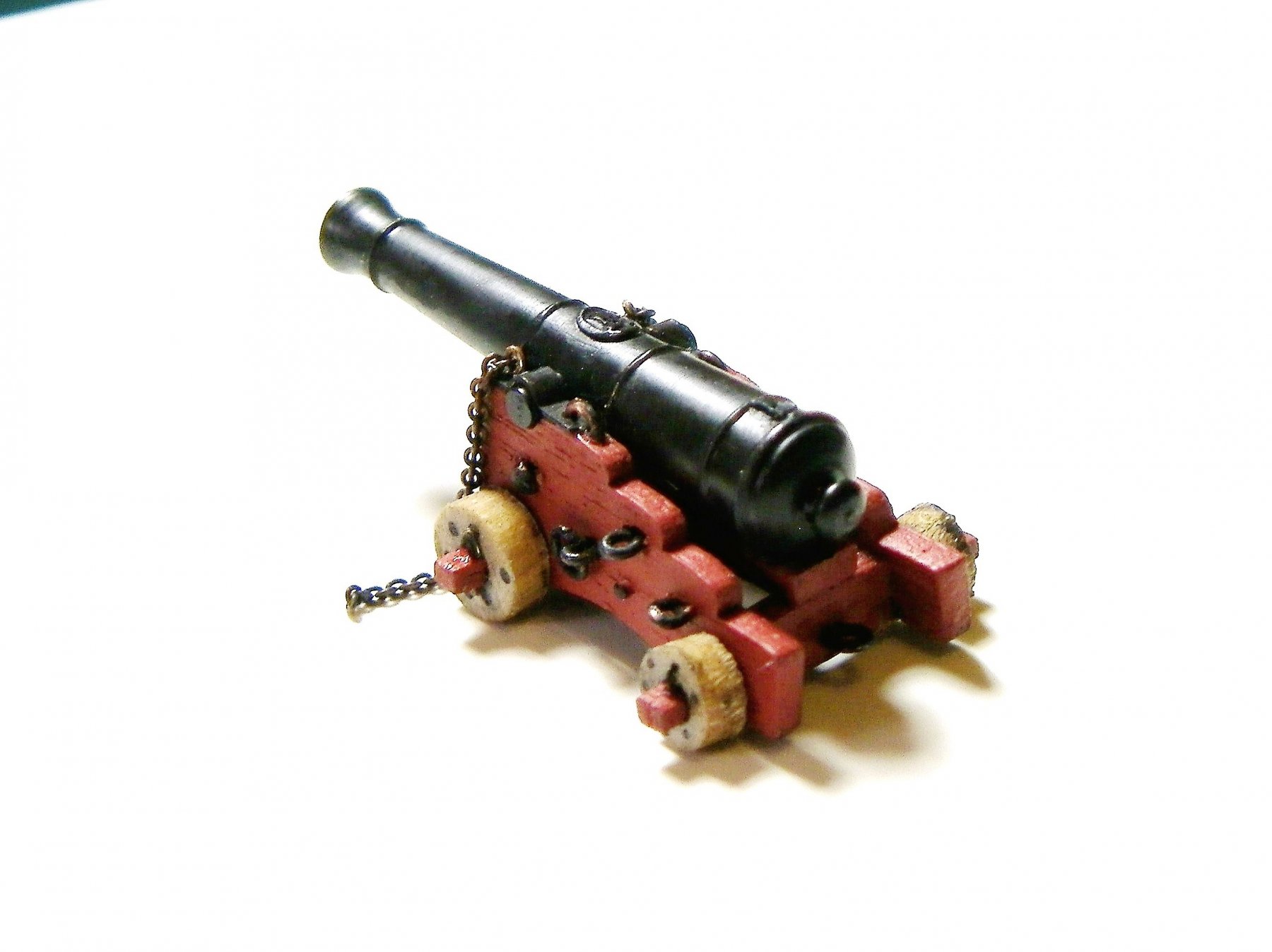
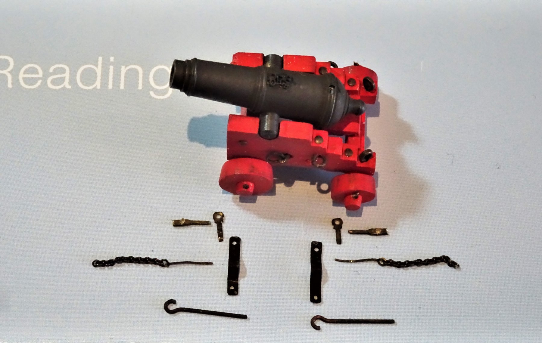
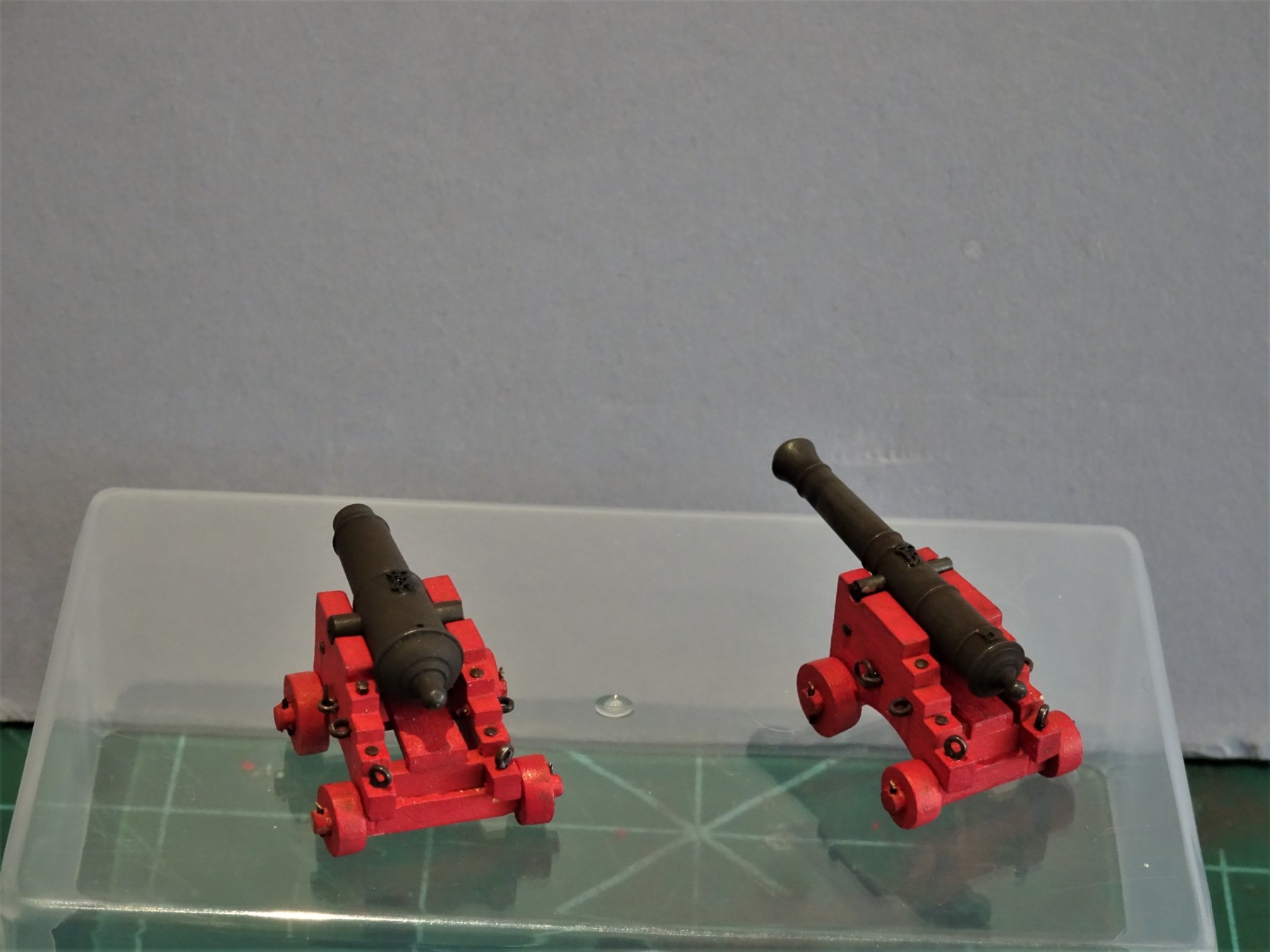
Post 73 Completing the Guns (Part 2) I don't glue my barrels to the carriages, preferring to hold them in place with the capsquares. I had previously made the capsquares but these now need finishing with the holes drilled to take the joint bolts and eyebolts. So far so good. When I made the Pegasus guns I added the bolt that secures the cap square in place plus the key and chain. 005 050 These were at 1:64 scale, so replicating these fittings at 1:48 scale would be a doddle, - right, - wrong. I think going slightly larger is more difficult as detail becomes more apparent. At this point I hit a sort of wall and have been fiddling around ever since my last post. 6274 These are the makings to complete the carriage furniture. The capsquares, eyebolt hinges, and joint bolts are fairly easy. It's making the key and attaching the chain that tests my sanity and patience to the limit. The Chain is some tiny stuff I have in stock whose origin is now obscure. 48 links to the inch just about right for the purpose, but still quite tricky to attach to the key in particular. Working out an approach and method is the first hurdle, handling the tiny little beggars is the second. I have spent several days faffing around trying to fit these tiny additions, the chain links are so small that I have to seize them to the key and retaining eyebolt, using very fine wire, and the more the gun is handled the more the finish is affected. 6334(3) From 12" normal viewing the result doesn't look too bad, from some angles anyway. 6335 The joint bolt fashioned from a cut down eyebolt, I am fairly happy with. 6329 Not entirely sure about the height of the key bolt or the size of the key, this is the area that bothers me most. The difficulty is fashioning these in an even smaller size. A further test is how does the finished gun look in place, no good doing it if it detracts from the look. 6344 6342 6349 Is the overall result worth the effort, I'm not sure and grow less so with the prospect of a further eleven guns to dress. I will give it one last go before I start on any further guns. B.E. 26/02/2019


.thumb.JPG.d88ebf669ff91a839b21d4ae4df30a22.JPG)


- 574 replies
-
- 22
-
-
- cheerful
- Syren Ship Model Company
- (and 1 more)
-
Thanks Dave, I agree narrow brass strip is the way to go for the metal stropped cat blocks, the tricky bit is getting the central disc where the sheave is located. I've made a few anchor buoys in my time and scratched the ones for Pegasus. For Cheerful tho' as they were available I took advantage of Chuck's little offerings. These will still need the serving and slings adding which is the fiddly bit. The buoys are an awkward shape not that conducive to serving and I find the line needs pva-ing as I work down the buoy. In fitting the slings I find a needle is of great benefit. Regards, B.E.
- 574 replies
-
- 2
-
-
- cheerful
- Syren Ship Model Company
- (and 1 more)
-
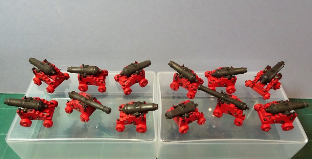
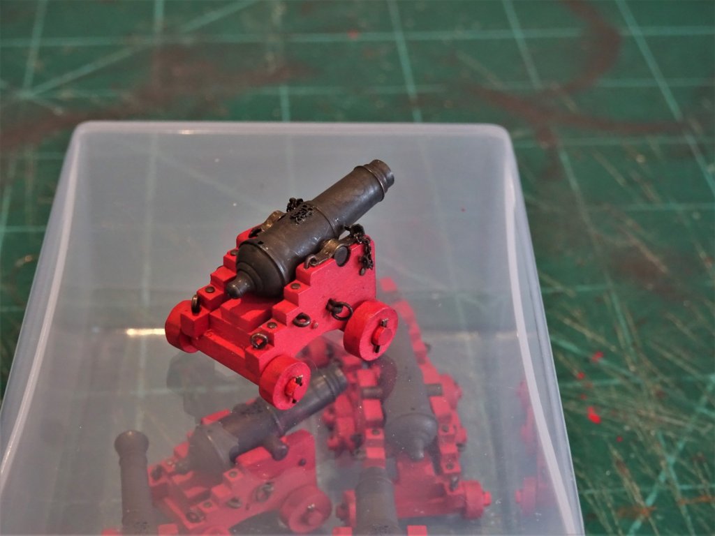
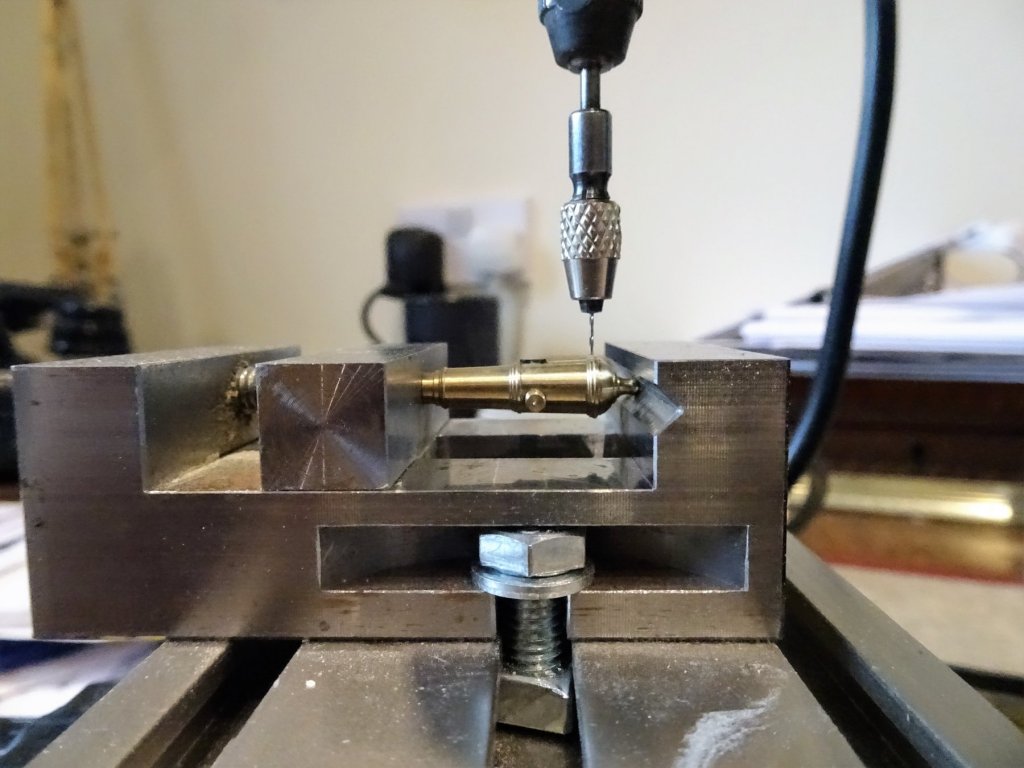
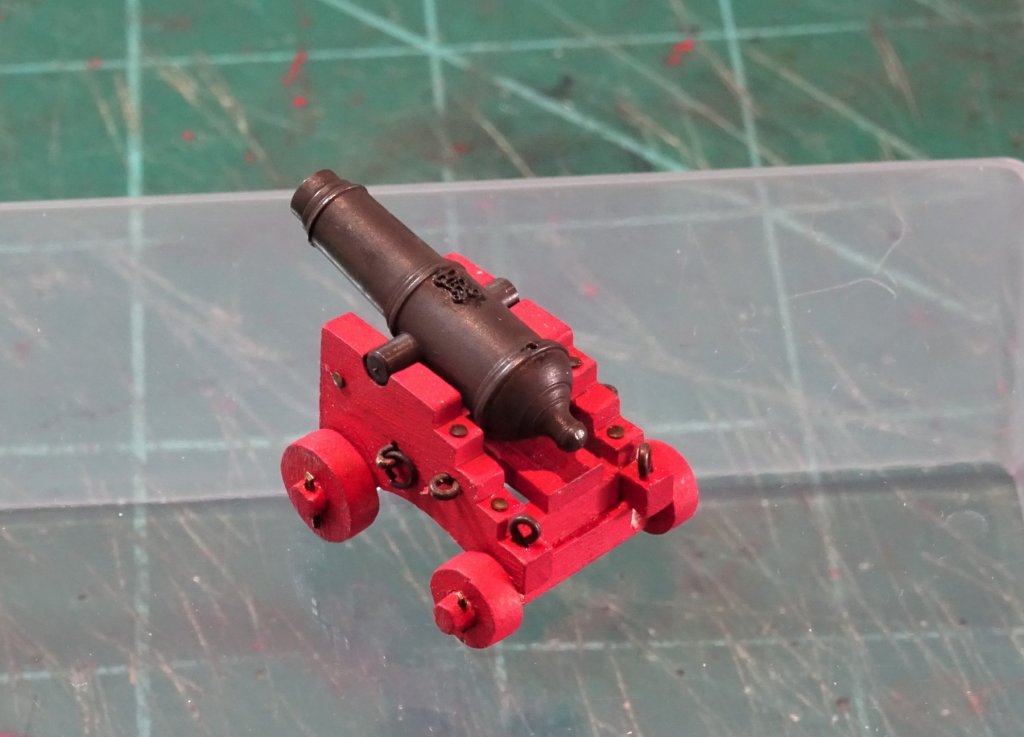
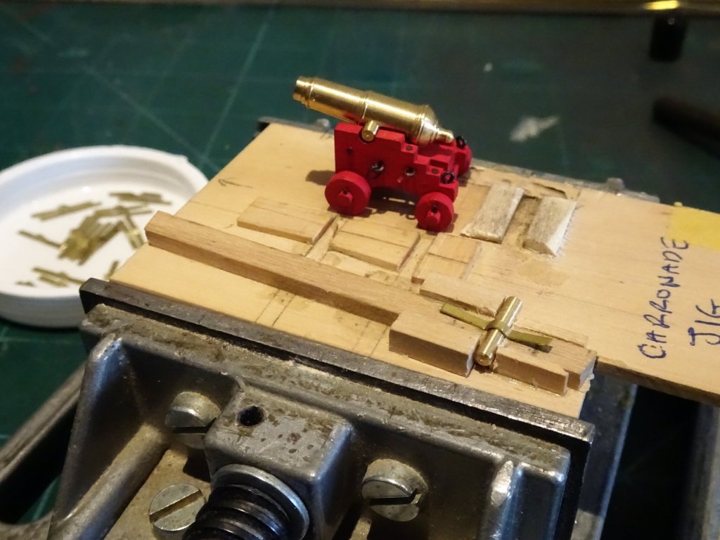
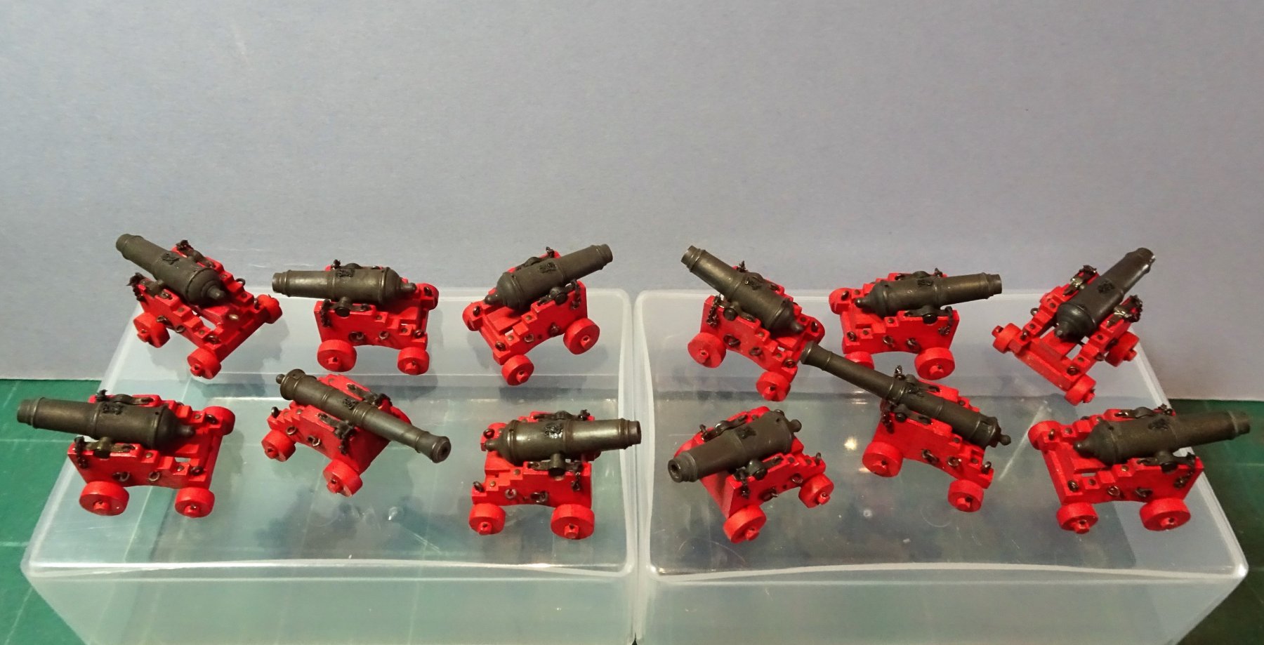
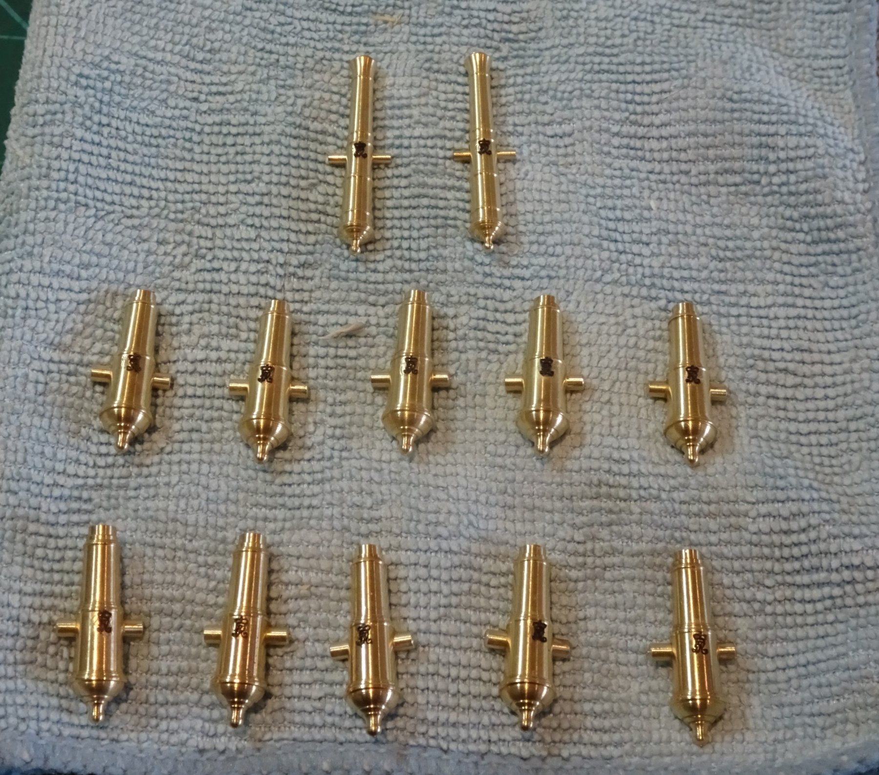
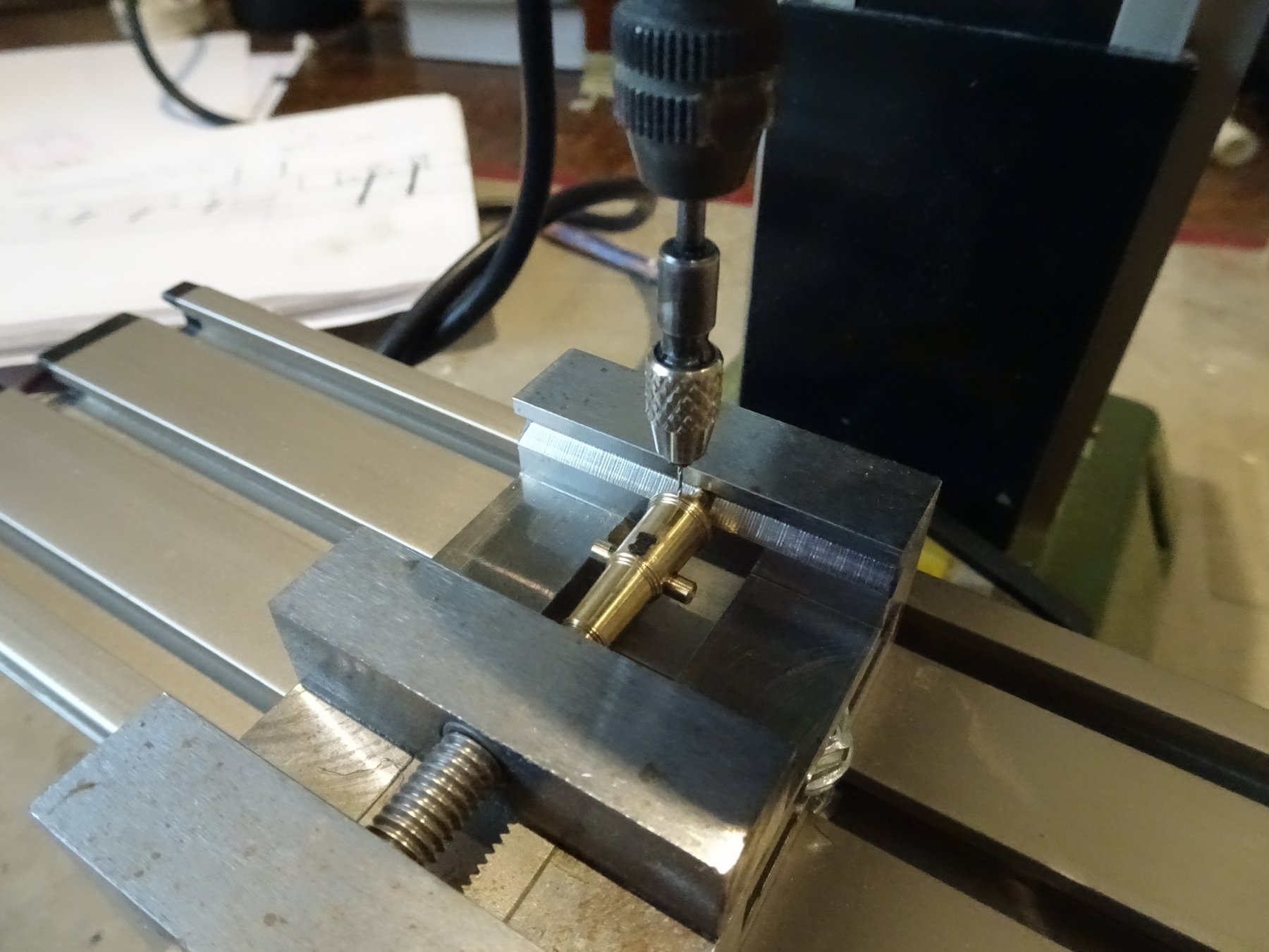
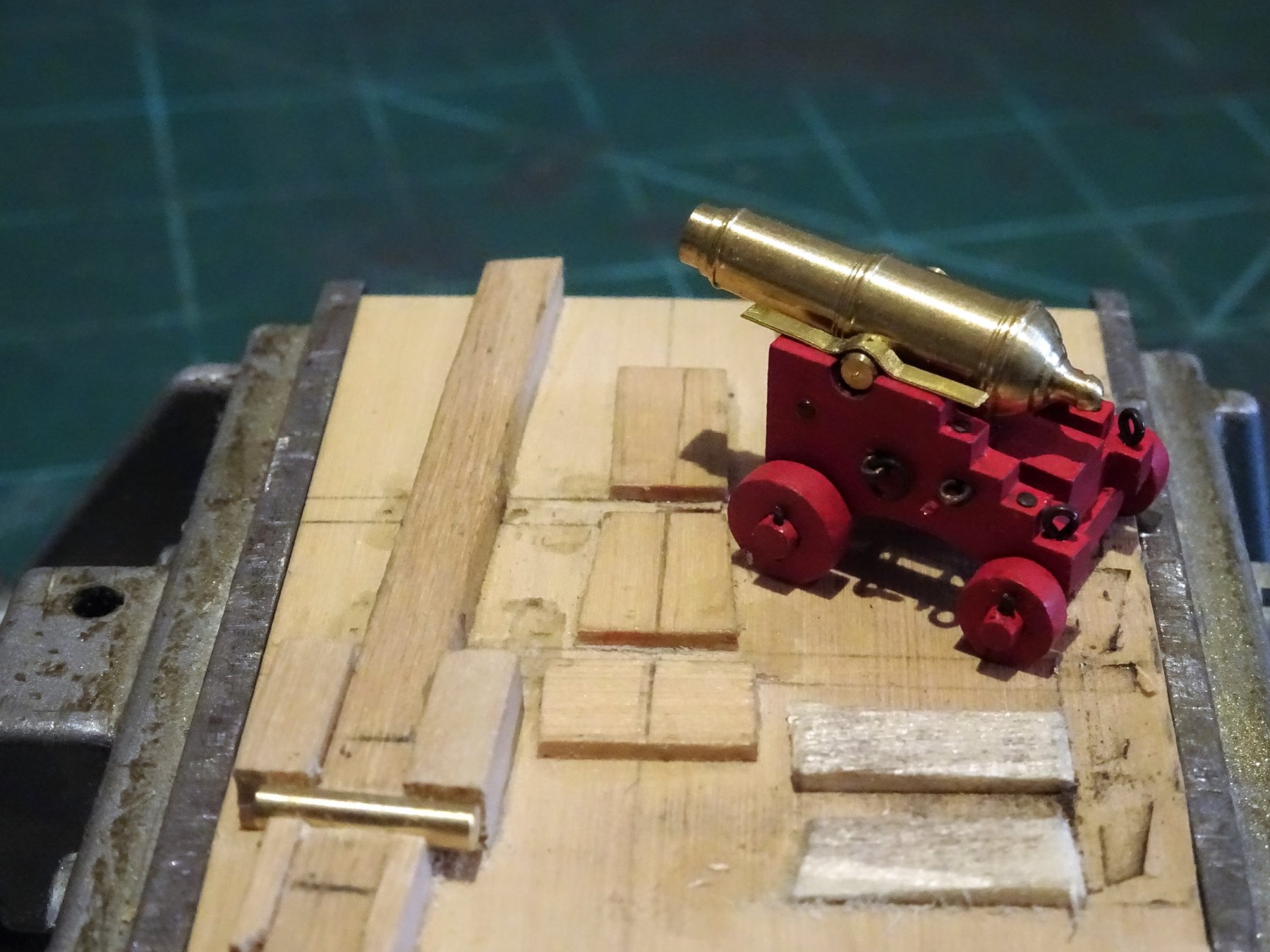
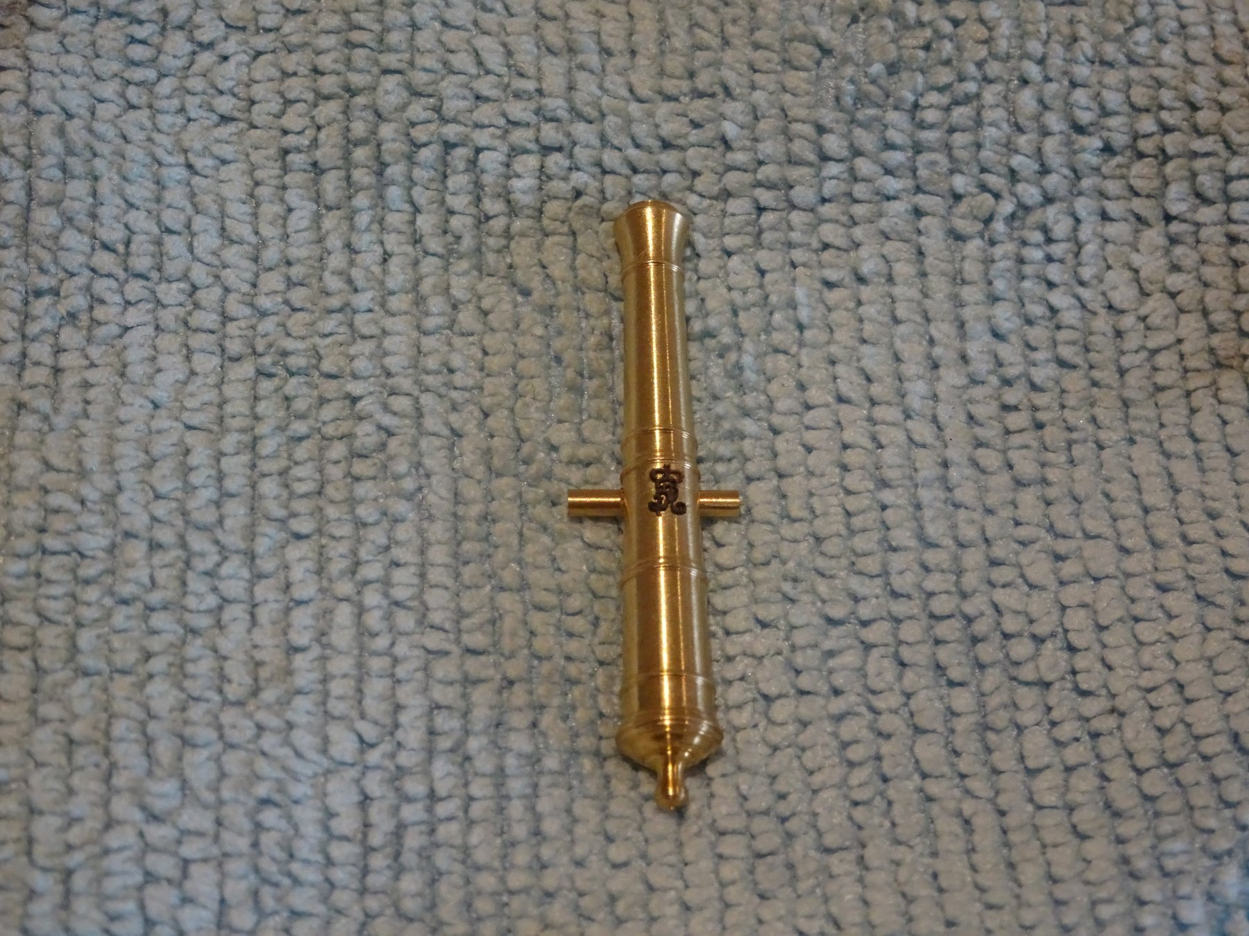
Thank you guys, @ John - only minor use was needed, and I also wore a mask. Post 72 Completing the guns. (Part 1) The first job is to apply the Royal monograms, using Chuck's delightful little offerings. 6208 A small detail that is missing from the guns are the vents, quite feasible to add at 1:48 scale. Easy enough to replicate on the long guns with a strip of brass drilled with a hole, but more difficult on the Carronades where the touch hole is in a casting atop the base rings. 6210 6211 I wouldn't have attempted this freehand but it can be done using the mill with a 0.5mm micro drill. Alternatively a small patch of 'lead' foil could be used to represent the covers to protect the touchhole. 6217 The blackening process is fairly slow because after each treatment tiny contaminated areas remain that require more delicate cleaning before re-dipping. 6230 However little by little an even finish is obtained. 6220 Here's a completed carronade after a light buff with a soft paintbrush. 6225 Once the cover is even the guns can be re dipped to intensify the depth of colour. 6254 Slightly darker after a further dip. 6247(2) The completed set The next step is to mount the guns, and that's a whole new exercise in fiddly detail. B.E. 22/02/2019


.thumb.JPG.a2e9fe571594f75e231ac17a81d91b2f.JPG)

- 574 replies
-
- 23
-
-
- cheerful
- Syren Ship Model Company
- (and 1 more)
-
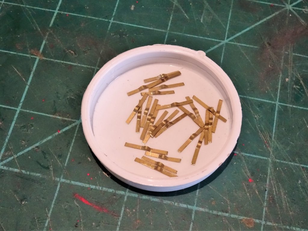
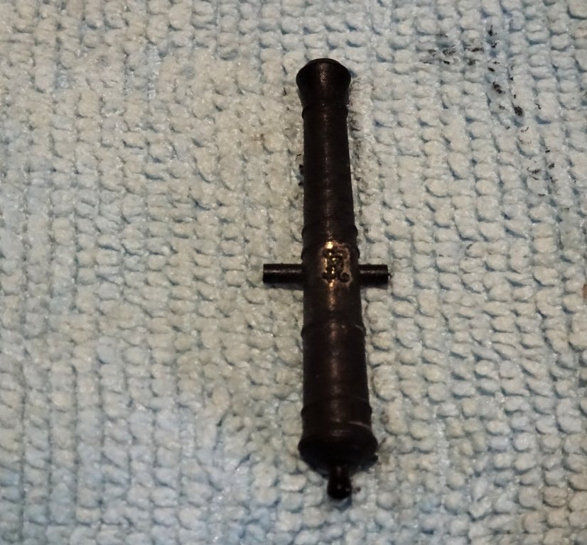
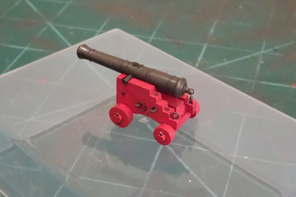
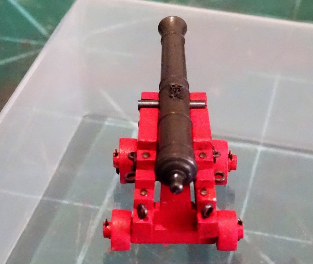
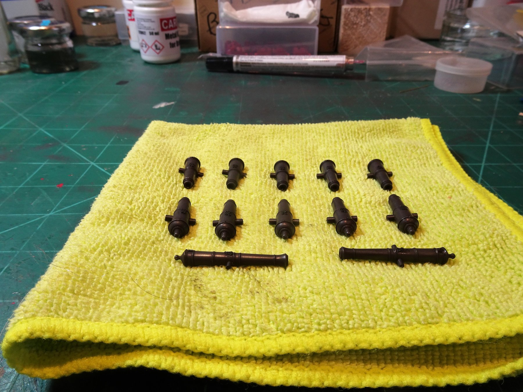
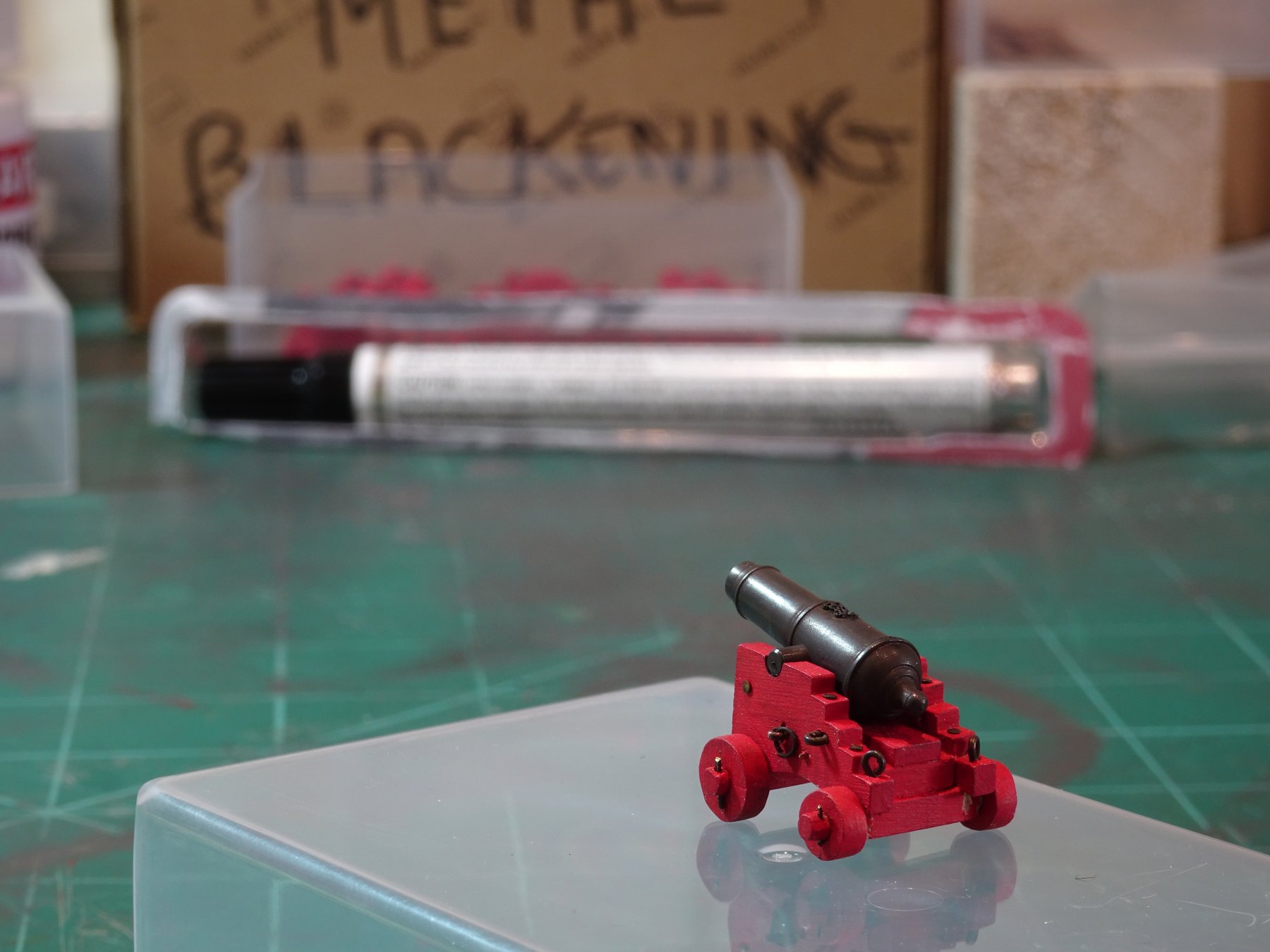
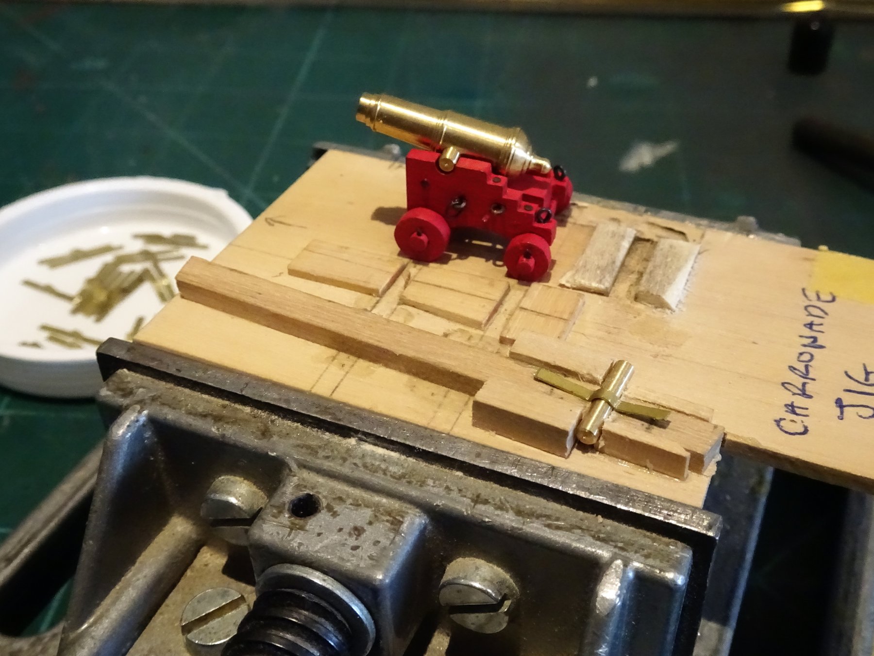
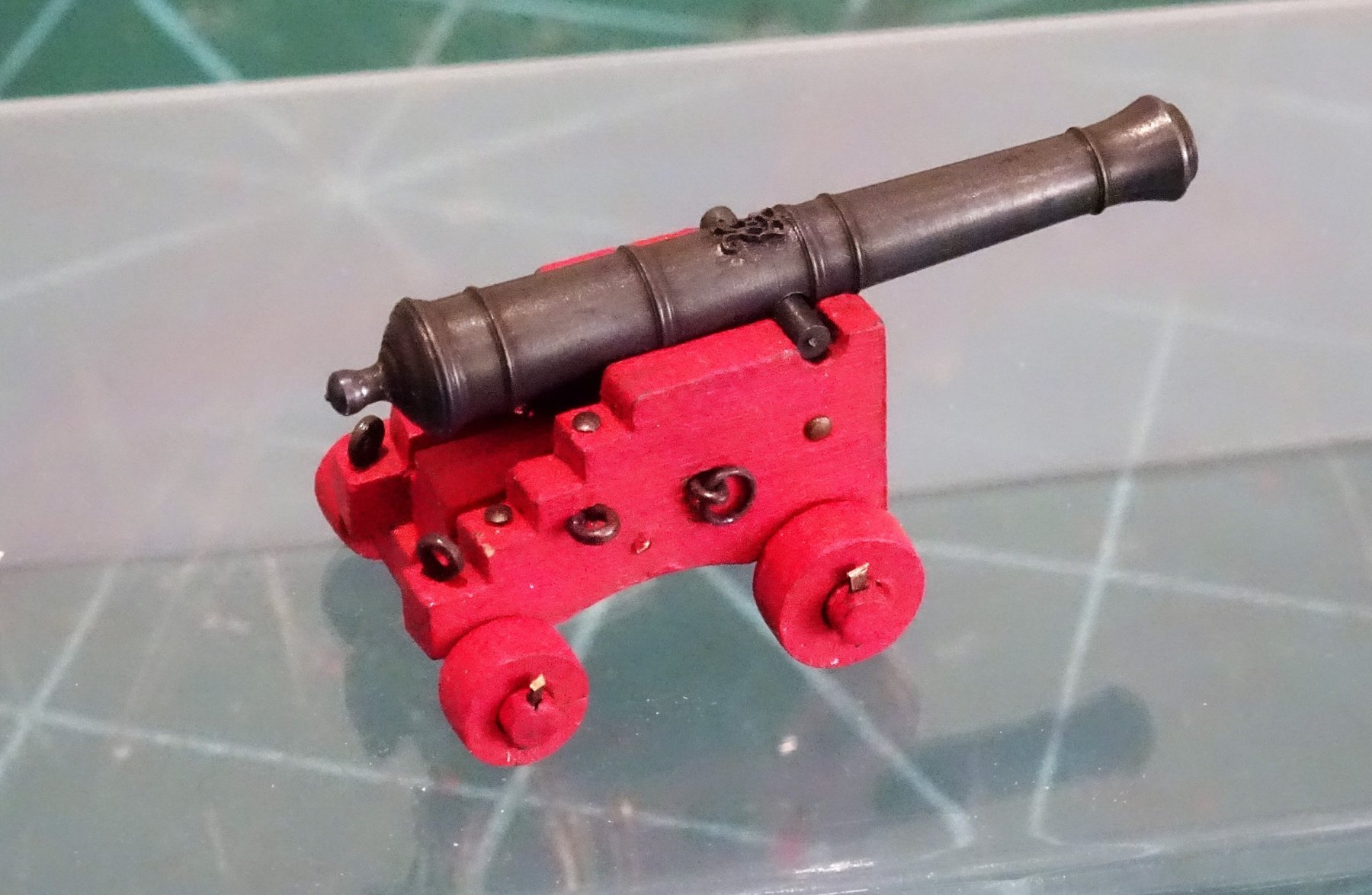
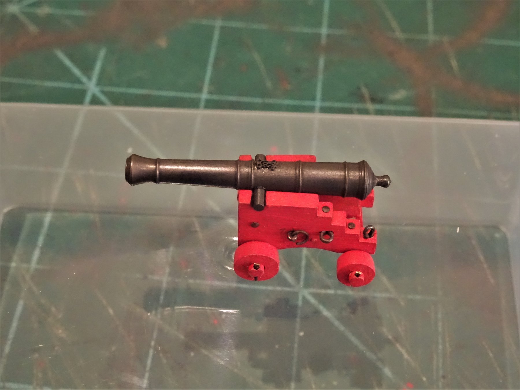
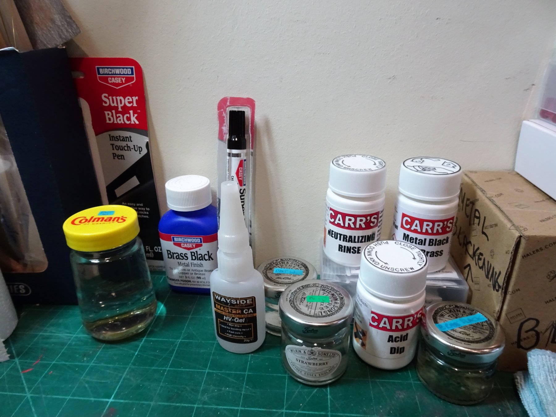
Post 71 Gun Blackening. I prefer to chemically blacken my guns rather that paint them but my first job is not to start blackening but to make the cap squares to hold the trunnions in place. 6174 A simple jig is made to hold a trunnion at the right depth and some brass strip is formed over this. 6176 It is important to use a pliable not too thick brass strip for this, otherwise the bending process can prove quite difficult. I am using some 0.25mm x 1.5mm brass fret strip left over from my Pegasus build. 6173 With the set made I can leave the finishing off until later. 6207 All the necessary stuff is assembled. I am using a 29/64" long gun to work out the procedure I will use. I am particularly interested in how the GR monogram will respond to the various procedures which will determine whether they are applied pre or post treatment. 6185 A medium sized monogram is blackened and fixed to the barrel using a spot of CA. This has been pre-blackened using some USA stuff called Birchwood Casey Super Black touch up pen which works very well but seems to be rather nasty stuff to the extent that its sale is banned in California. Still I will have very short exposure to this stuff. The barrel is scrubbed in soapy water, rinsed in distilled water, dipped in acid, rinsed again, immersed in the brass black, and rinsed again. 6197 You can see the unblackened area around the monogram which is due to ca contamination. The good news is that the monogram has not been affected by any of the processes. A scalpel blade point is used to scrape away the ca overspill and the process repeated. I found it easier to put tiny spots of ca onto the barrel directly and then place the very tiny cypher and apply a little pressure. 6199 6200 So this is the effect after two 3 minute immersions in diluted Carrs Metal Black to Brass. 6198 6202 Quite happy with the way things have gone and I will now carry on to complete the full complement of ordnance. As an aside if you compare the finish Chuck obtained using paint and weathering powders, what a great job he made of 'iron' ising his guns. B.E. 19/02/2019


- 574 replies
-
- 22
-
-
- cheerful
- Syren Ship Model Company
- (and 1 more)
-
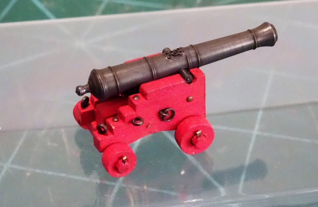
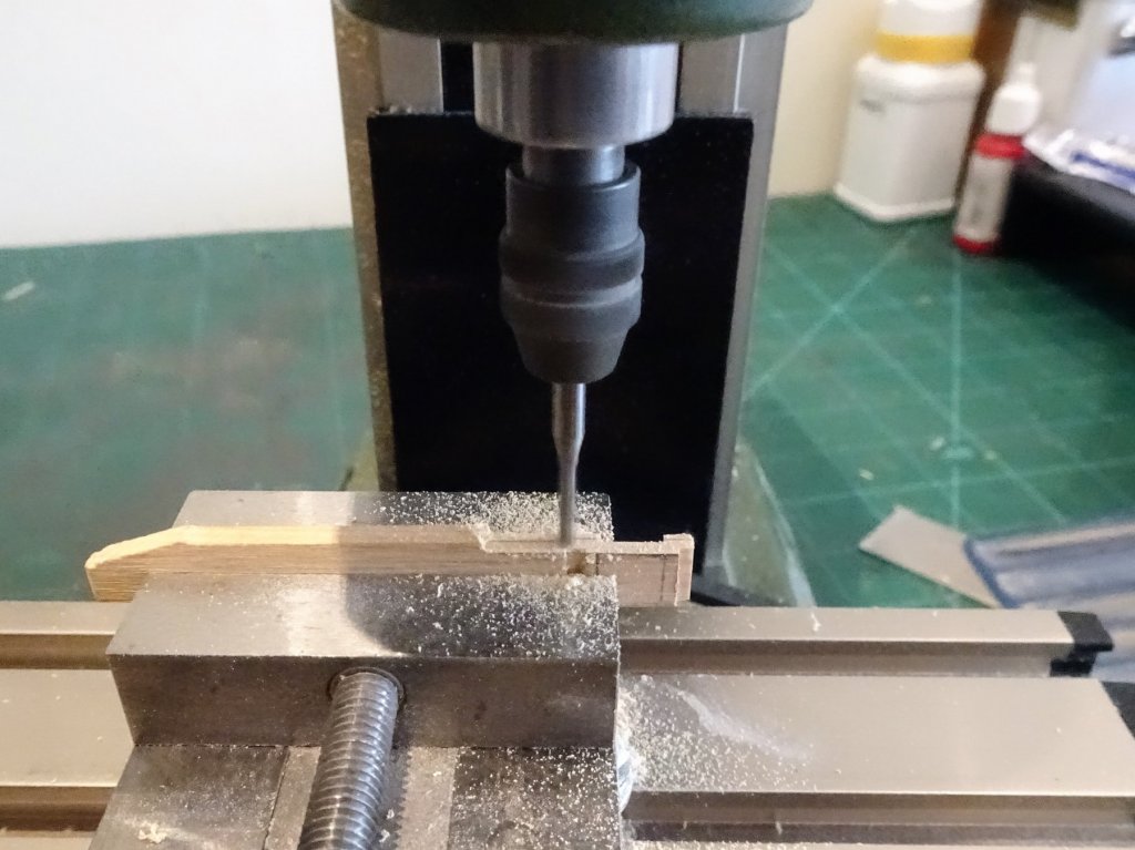
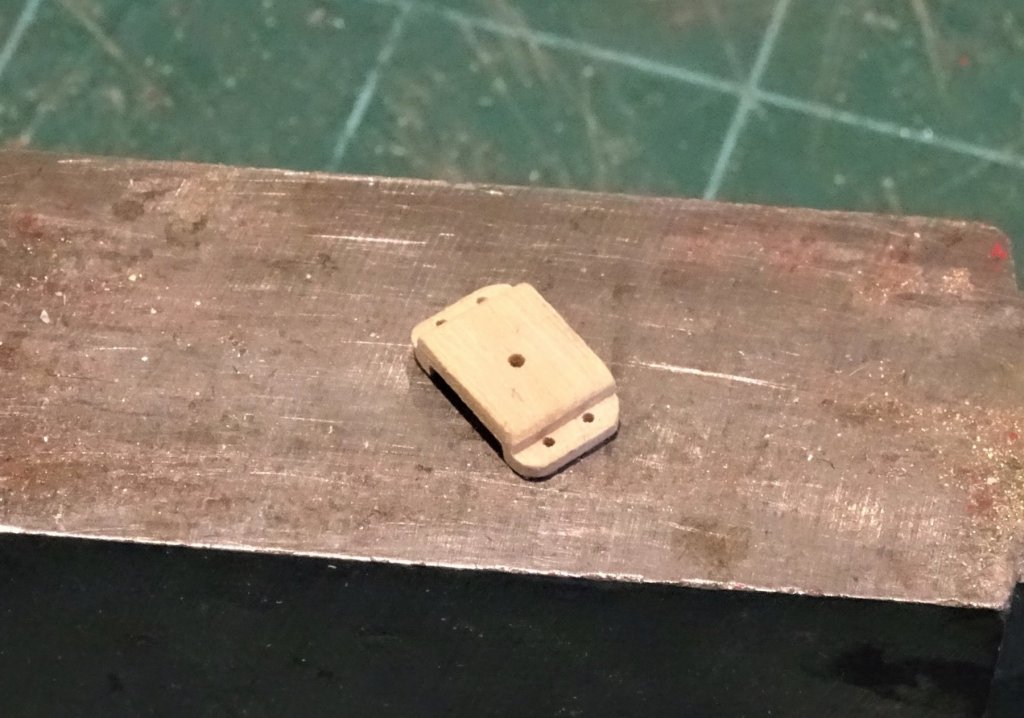
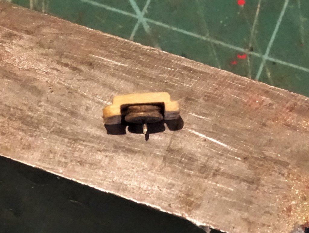
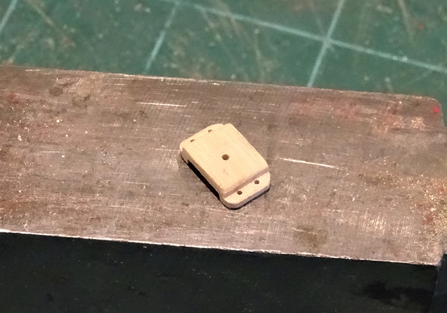
Cheers Guys, and for all the 'like' hits, much appreciated. Post 70 Fixed Block This is a convenient point to make the fixed block for the stem to take the jib outhaul. Taking measurement off the plan the block is made from a scrap of 3mm thick boxwood sheet. 6136 I cut the profile on the little mill, and finished it with files and sanding sticks. 6138 6139(2) 6140(2) 6145 The sheave was made from a slice off some Ramin dowel. 6149 6147 The bench will now be cleared so I can get down to a spot of gun blackening. B.E. 17/02/2019
.thumb.JPG.a3634bcfc48cae7ac672ddb01a6b6d53.JPG)
.thumb.JPG.52808590b74511ffd67f9e7386bb5ab1.JPG)

.thumb.JPG.194f6a373ef5f012bc108f737ec98b19.JPG)
- 574 replies
-
- 22
-
-
- cheerful
- Syren Ship Model Company
- (and 1 more)
-
I have just ordered the Longboat kit, and as with Cheerful I will have your log and excellent work to follow as an example. Thanks Rusty. B.E.
- 152 replies
-
- 1
-
-
- medway longboat
- Syren Ship Model Company
- (and 1 more)
-
Hi Chris, I've always been an admirer of your designed models but have accepted the timber limitations of mass produced kits which I have replaced mostly with Box. For double skinned kits Limewood is fine for the first planking, but as with my Pegasus build I replaced the second planking with a thin Boxwood strip obtained from: http://www.originalmarquetry.co.uk/product_details_335.htm This is fine for 1:64 scale models and the beauty is that it comes in varying widths to allow for shaping of hull and deck planks, and also very easy to work. This is what I would do on your proposed Alert if it becomes available, in the absence of better stuff. The inclusion of 'usual' kit wood, would not put me off buying the kit if I liked the look of it, but as a small enterprise I think you need to follow Chuck's lead and lean towards a more high end market. I consider myself an experienced kit basher rather than a scratch builder, altho' there is not much bashing required in my current Cheerful project. This is what attracted me to Chuck's Cheerful Kit. Well drawn plans. Well written online guide to building the model. Clear history of the subject model Provision of the main areas of the model in quality wood - keel, stem etc. Availability of kit specific timbers - Crown, Syren. Quality fittings and mini kits for those tricky to make items. All this makes for a pleasurable build experience and high satisfaction, eager for the next model. Regards, B.E.
- 906 replies
-
- 13
-
-
Thanks Dowmer, those hooks are quite small and once blackened and fitted there’s not a lot to see. Being basically a lazy builder I will purchase parts if I think they are up to scratch 😉 rather than make them, that’s why my Cheerful build is in the kit section rather than the scratch section. ps.: I have now modified the coamings following your timely advice a few posts back 😊 Regards, B. E.
- 574 replies
-
- 1
-
-
- cheerful
- Syren Ship Model Company
- (and 1 more)
-
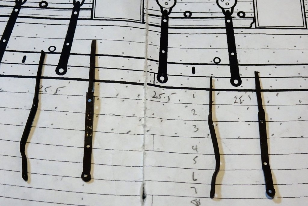
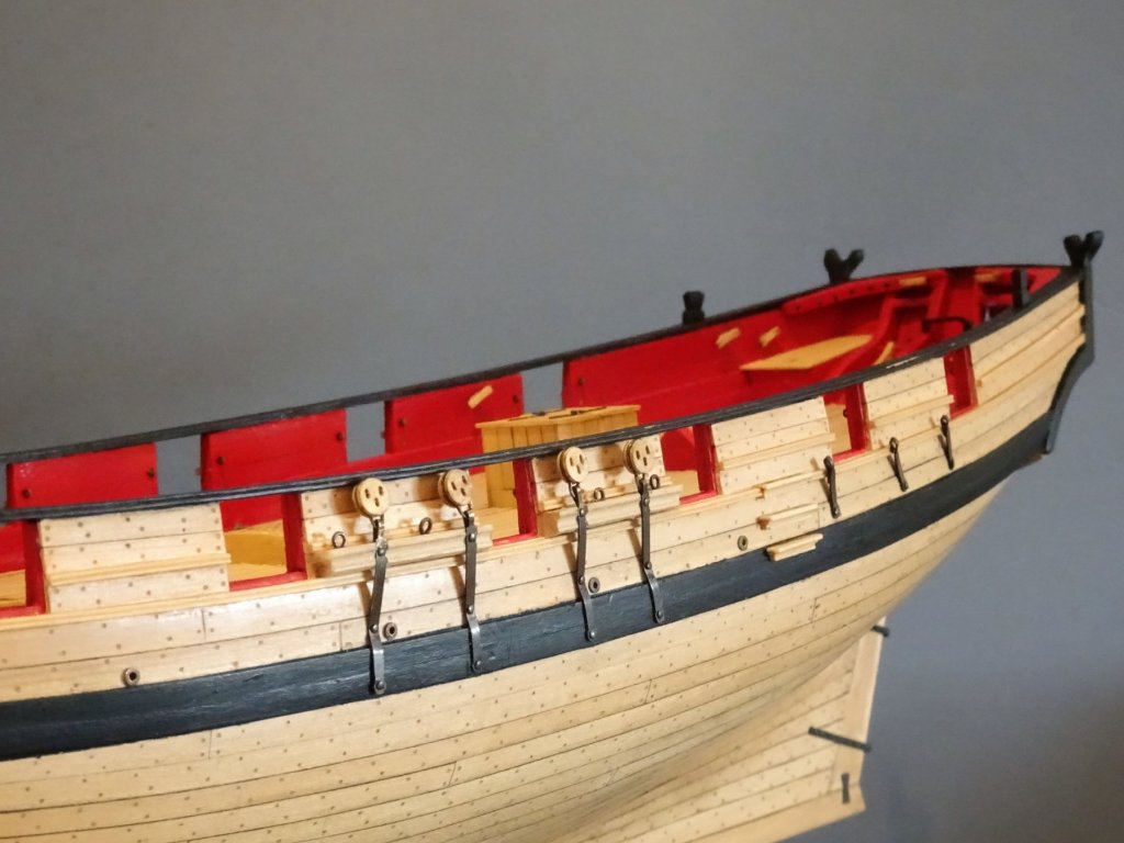
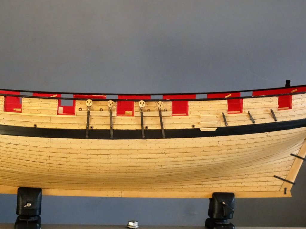
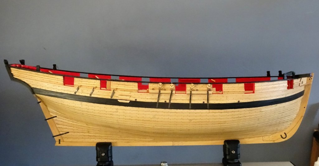
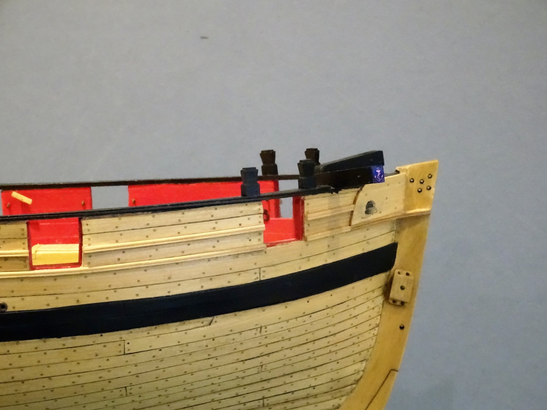
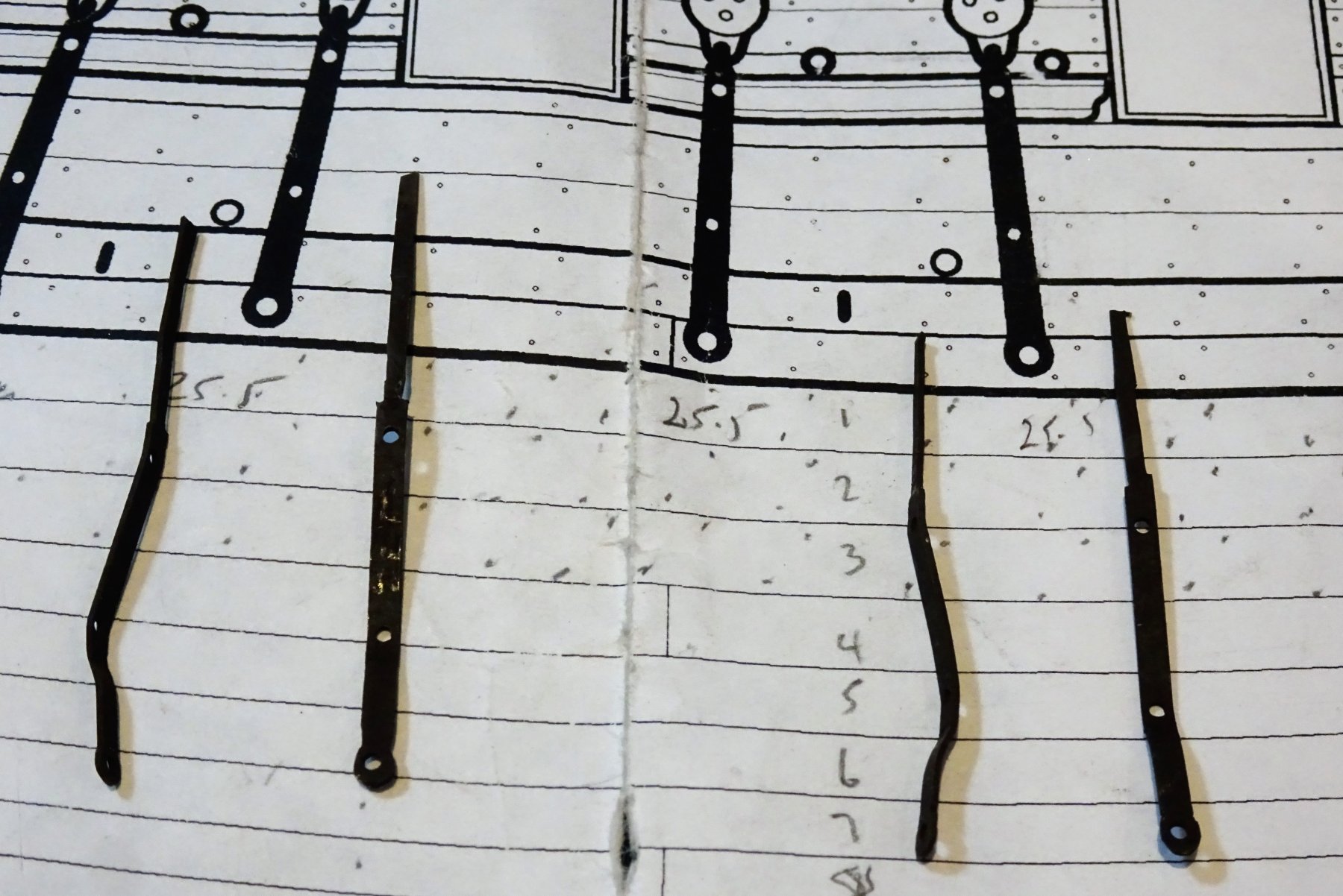
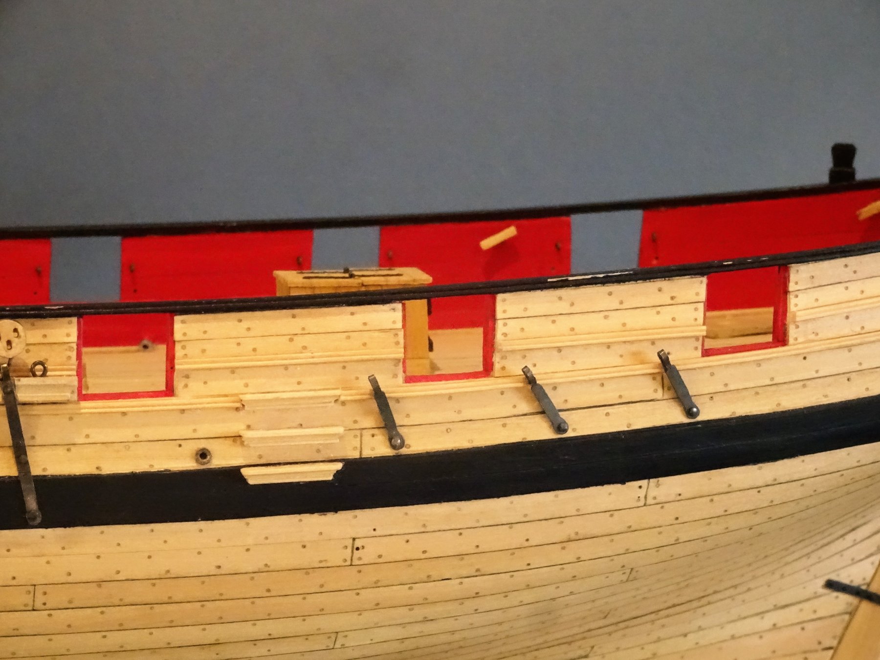
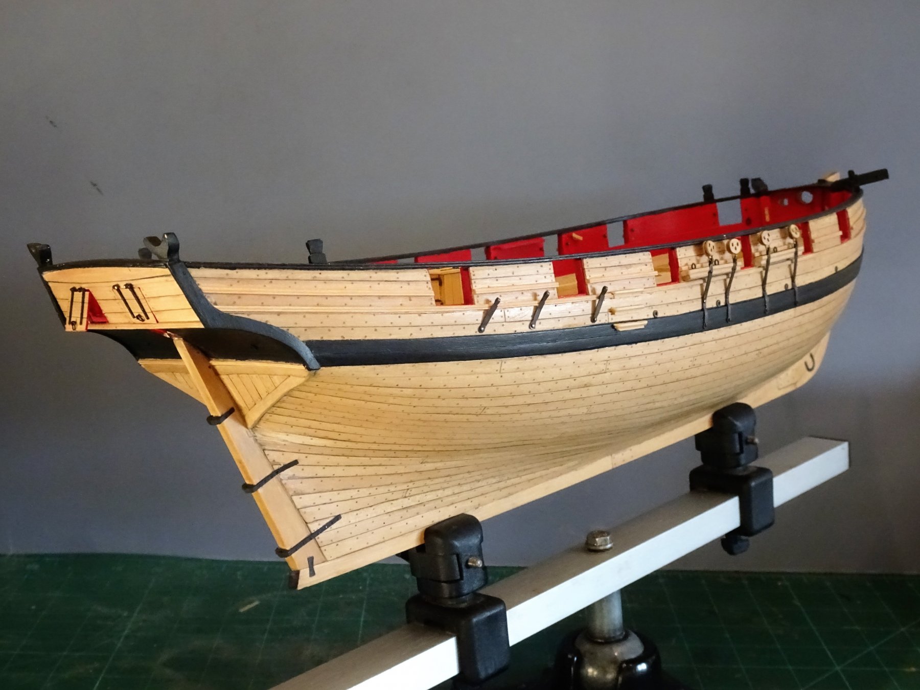
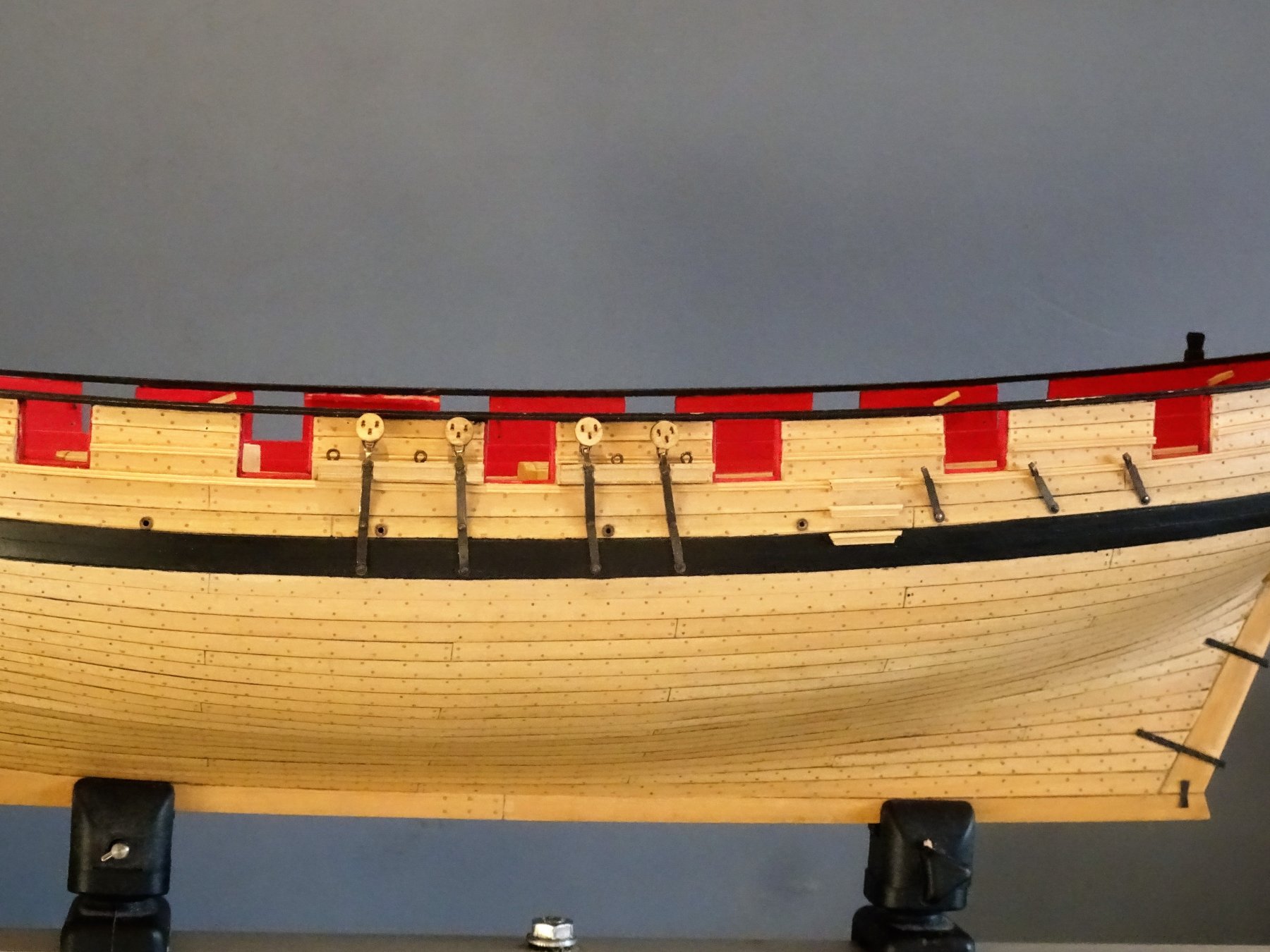
Post 69 Completing the Chainplates I now get back to fettlin' the Chainplates and with the deadeye strops completed I can now gauge the width of the chainplate fold over to secure them. A further 'on model' trial fit of the Chainplates to check positions and form the bends required where the Chain fits over the wale. 6078 This is a bit of a scary exercise and is done with the model supported on towels and a flat metal edge used to press the chains into shape. This needs to be done before blackening for obvious reasons. 6080 The chains are then blackened; washed in soapy water, rinsed, dipped in acid, rinsed again, submerged in the brass black. and once again rinsed. I also tested a deadeye in the blackening fluid to test the effect on the Boxwood. There was no visible effect on either the colour or the stability. This is just as well as once the chainplate has been messed about fitting and adjusting the connecting loop, a further dip in the brass black is required. This is one of the downsides to metal blacking items such as this rather than painting them, but for me the finish is far preferable. All this is a fiddly exercise, particularly getting the deadeyes to sit reasonably level with each other. Tiny differences in the strop and chainplate loops contrive to work against you, to produce an uneven top line. 6129(2) In relation to the fixing of the chainplates I have followed the Admiralty plan and placed the second bolt above the wale, also shown on Chuck's plan, rather than have the two fixings thro' the wale. It took a days work to complete one side of the Chainplates, with still a little more adjusting and touching in to do. Backstay plates I am using Caldercraft 5mm brass etched hooks for the rigging attachment to the Backstay plates so the plate loops need to be made to accept these. 6133 6119 Much quicker to make and fit the backstay plates. Overall three days work to complete and fit the ironwork. 6125 6120 6128 6131 I can now leave the Blacksmiths Forge and return to the Carpentry shop. B.E. 15/02/2019
.thumb.JPG.23a496033c0750711bef8ab91ebe62bd.JPG)


.thumb.JPG.10f2d4b981b77ff9d27bea9c256827bb.JPG)
- 574 replies
-
- 29
-
-
- cheerful
- Syren Ship Model Company
- (and 1 more)
-
Hi Martin, de-ionised water (distilled water) is simply used to neutralise the acid before I dip in the blackening solution, and then to stop the process once the depth of colour is achieved. Cheers, B.E.
- 574 replies
-
- 1
-
-
- cheerful
- Syren Ship Model Company
- (and 1 more)


.JPG.fb85db02e331830c429e778bfdd8b06b.JPG)


.JPG.deb37c040f52a2f8f46b31a56fa09c73.JPG)


.JPG.ca8a374bc70e3bee4129a8ee5abc95ae.JPG)
.JPG.3970460dede8b8587d65343ad37b6496.JPG)
.JPG.d7ae8aeac9f6866e42266c75bb8649c8.JPG)
.JPG.3eb6b0cac36673f1ca6f9164b4ba08cf.JPG)


.JPG.a6708932075abdce02dc3eb634e2fda2.JPG)


.JPG.afccd6a3d9a418e1723f6dba235d27f4.JPG)


.JPG.ae101f230bda3204409496fbe052b369.JPG)
.JPG.37f557b0739abde68dce77562df91b81.JPG)

.JPG.64244a6ecc78647be8157f3c66f454a4.JPG)
.JPG.9476461f174d0755bfcc7144405e27d1.JPG)

.JPG.fbbc64e3b9e30bd701ff523df463599c.JPG)