.JPG.ca33079f5815b861e67b9c2cccd37982.JPG)

Blue Ensign
-
Posts
4,571 -
Joined
-
Last visited
Content Type
Profiles
Forums
Gallery
Events
Everything posted by Blue Ensign
-
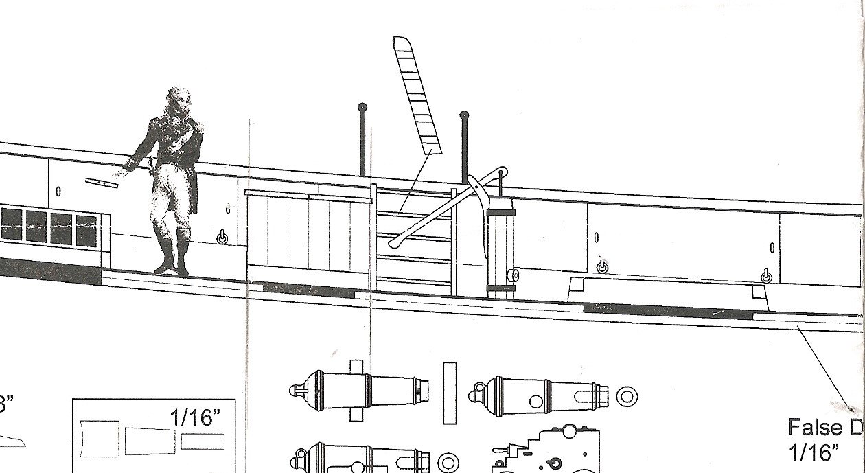
 Hardly perfect Dave, I think you must be going blind 😃 I shudder sometimes at the macro shots, but from 12" it looks ok, at least to my eye. It is the plan with the inboard profile and deck plan on it. I chopped my plans up to make them more easy to use, but this section may help you locate the ladder profile. Hope your finger stiffness eases off soon. Regards, B.E.
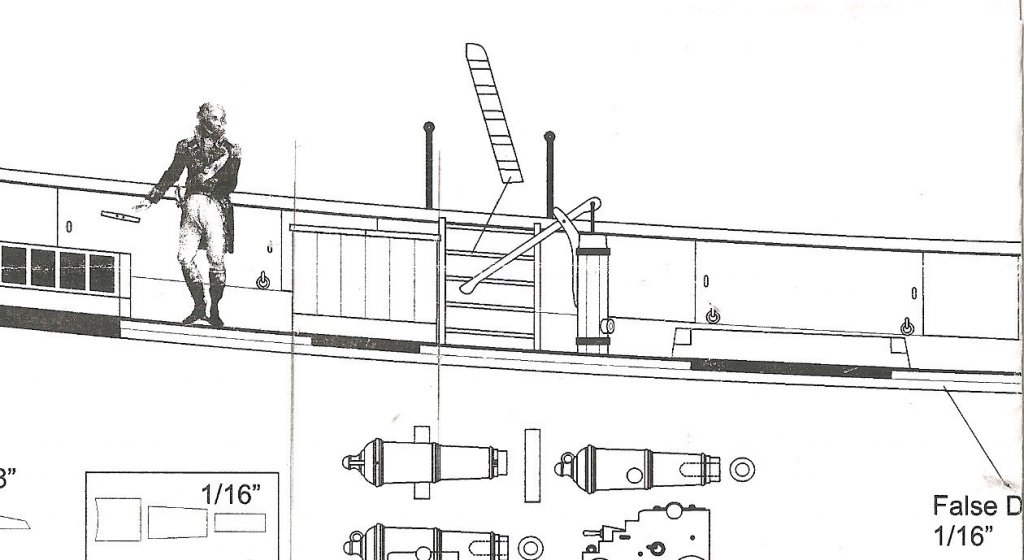
- 574 replies
-
- 3
-

-
- cheerful
- Syren Ship Model Company
- (and 1 more)
-
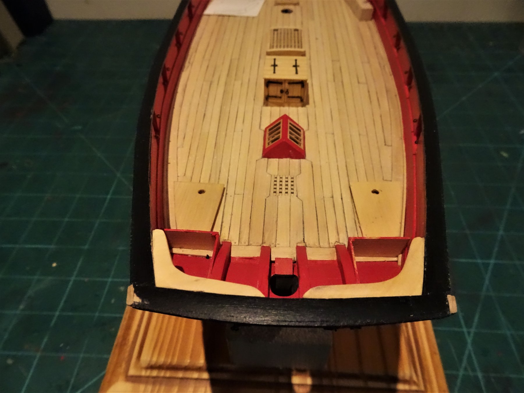
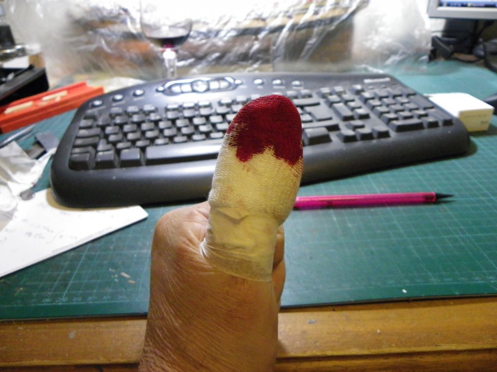
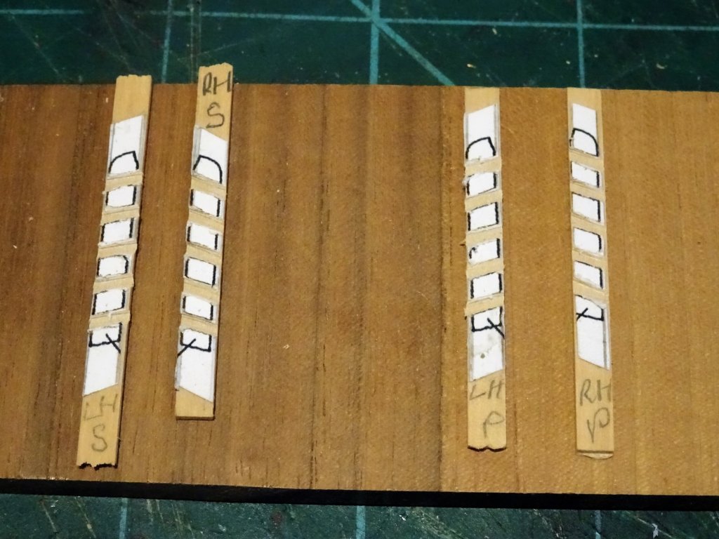
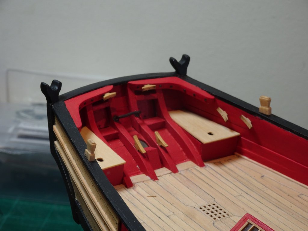
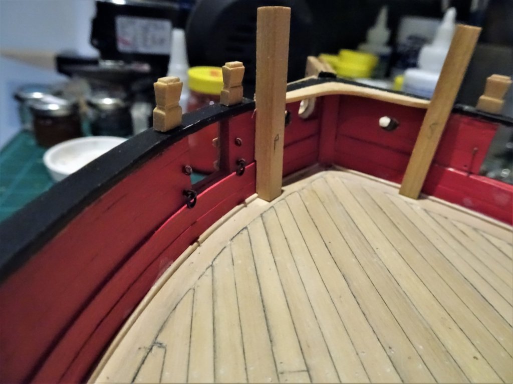
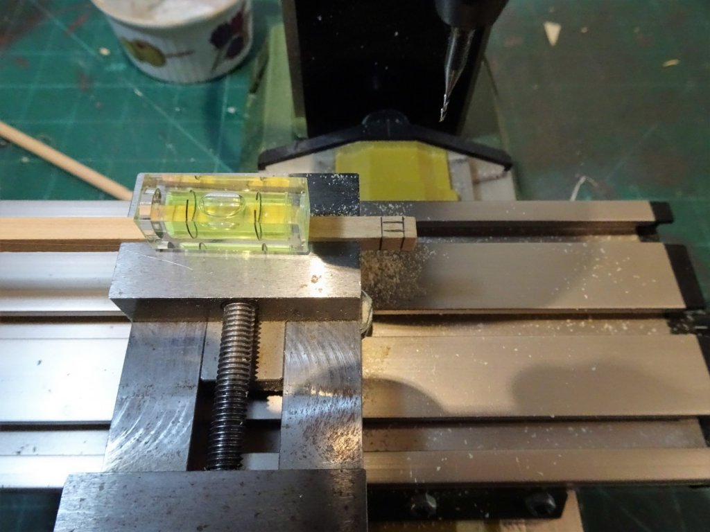
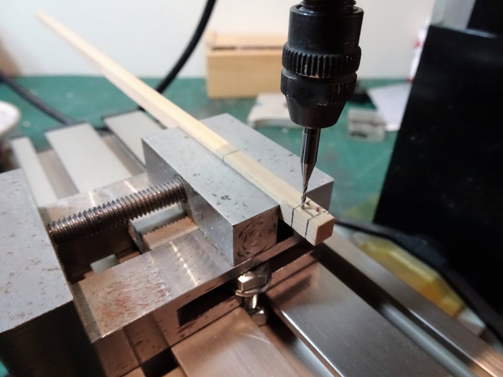
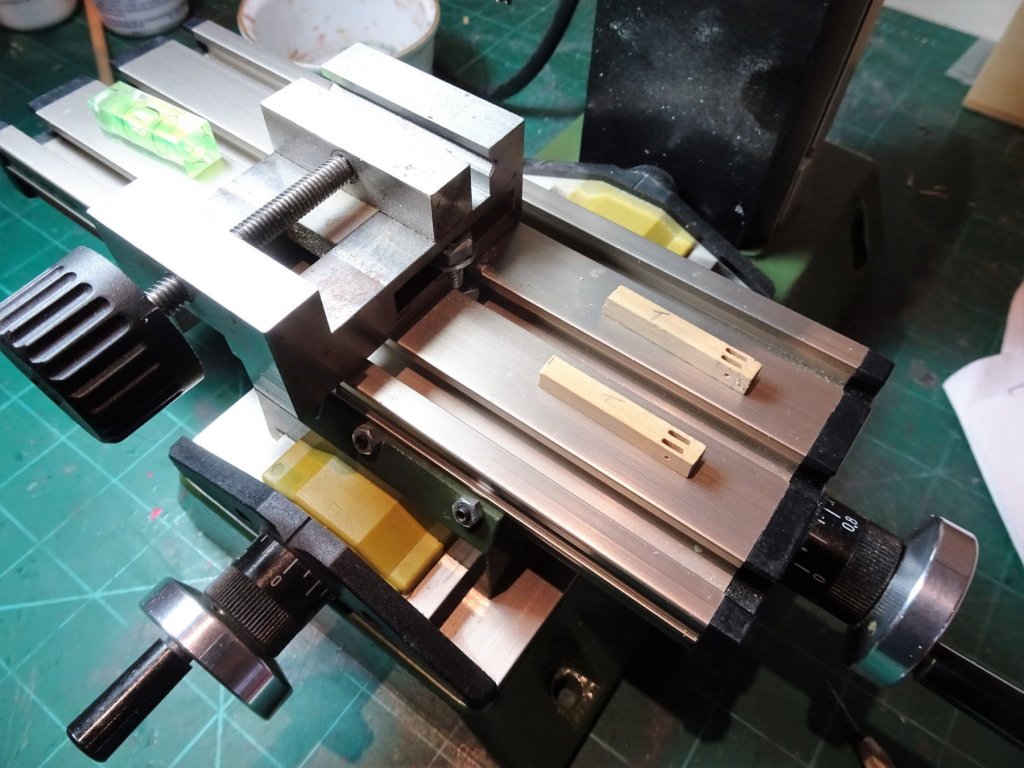
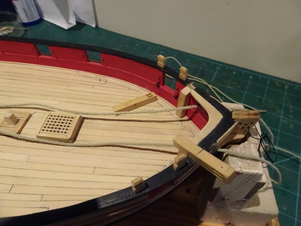
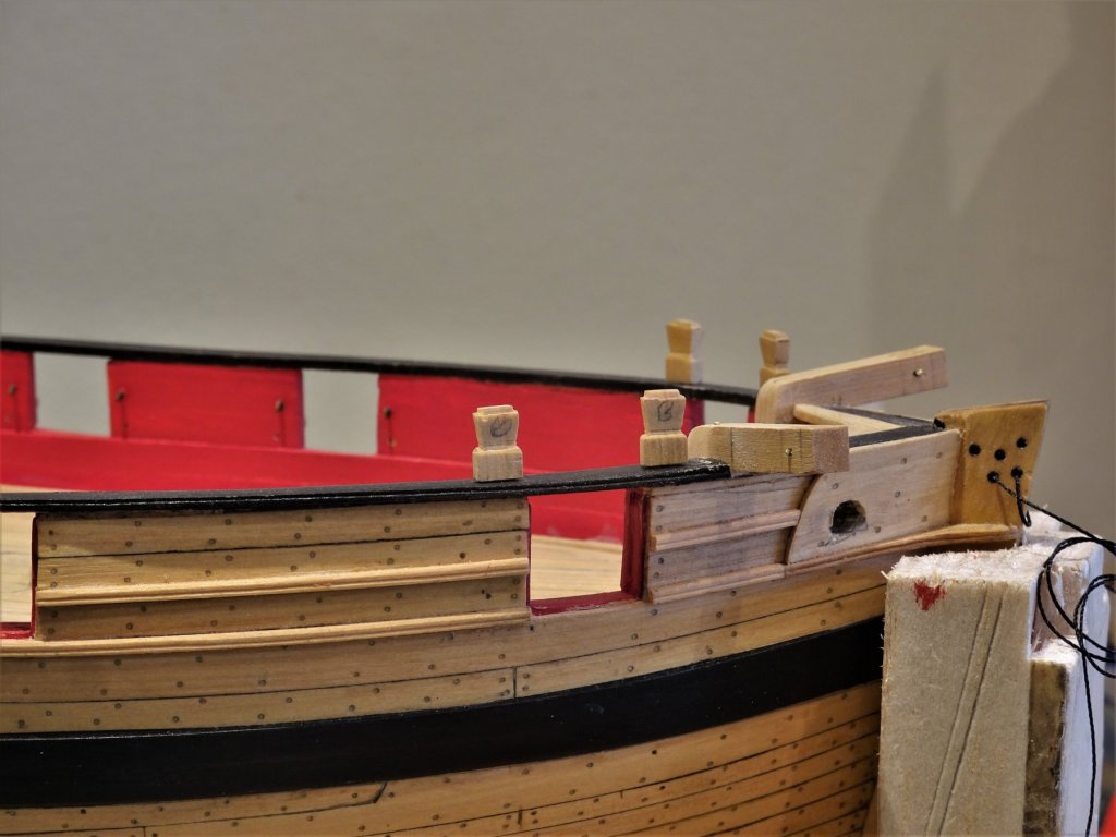
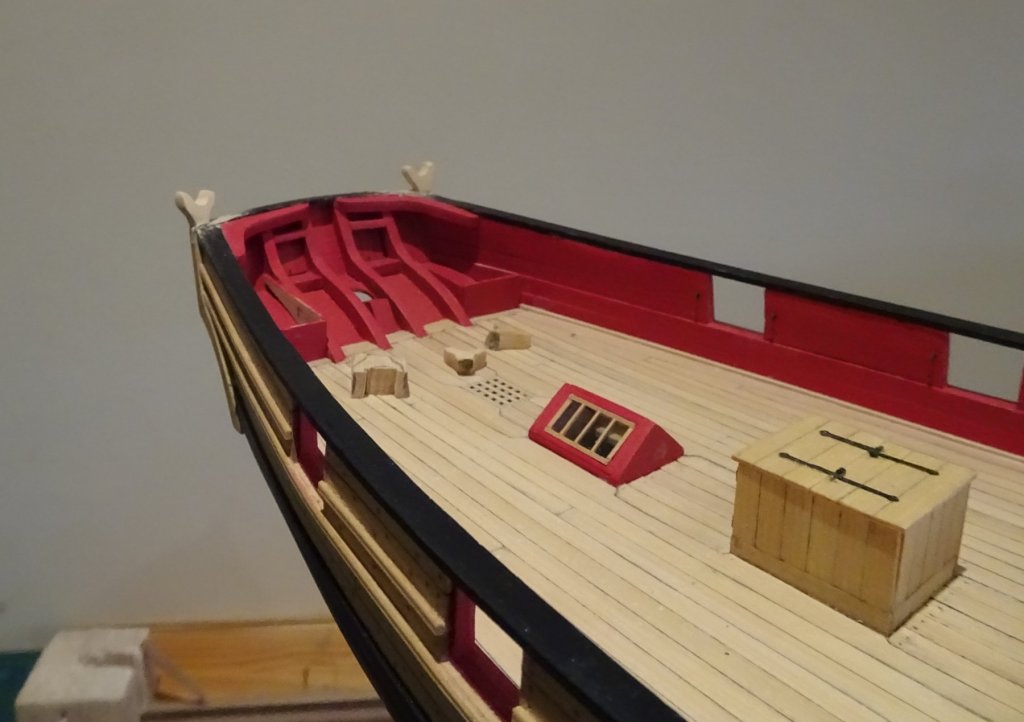
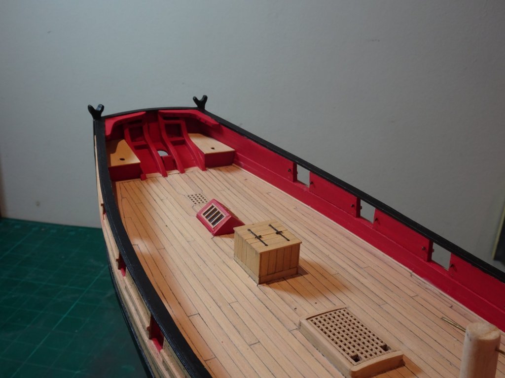
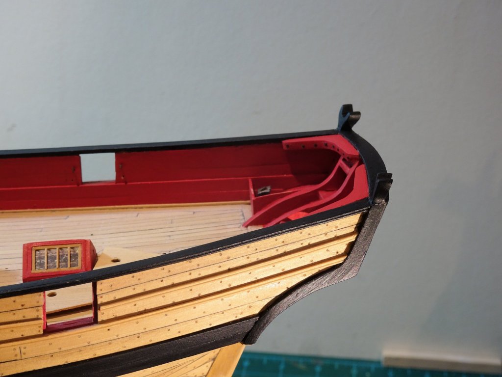
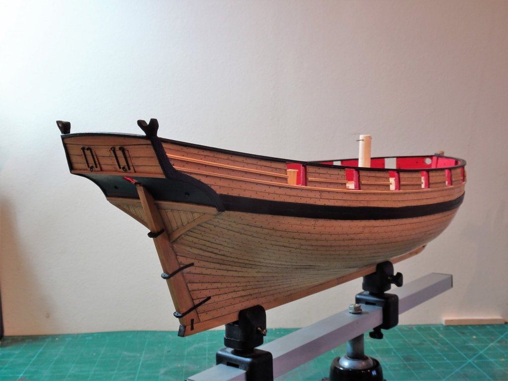
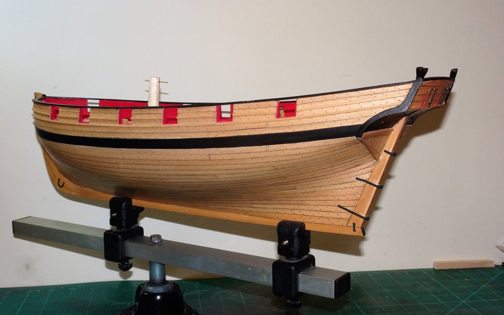
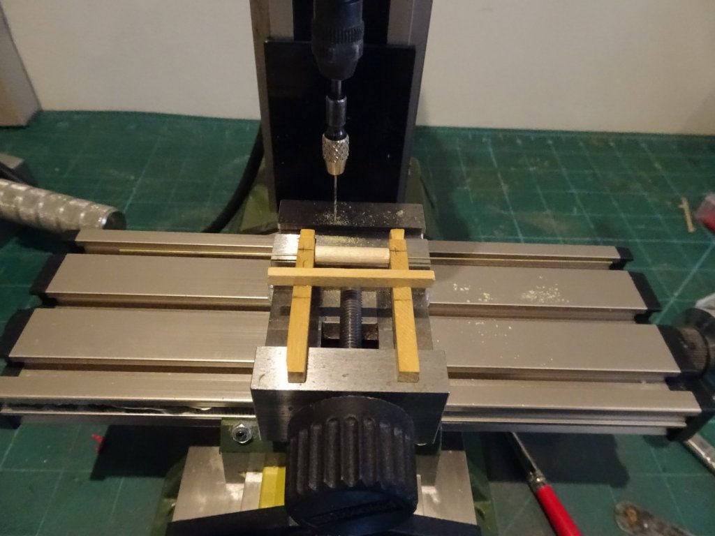
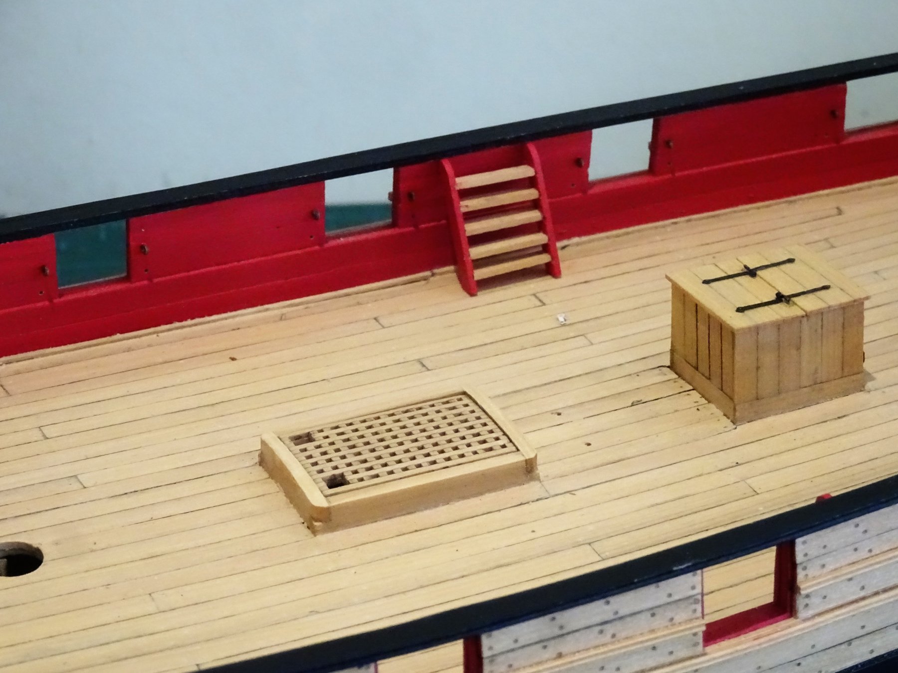
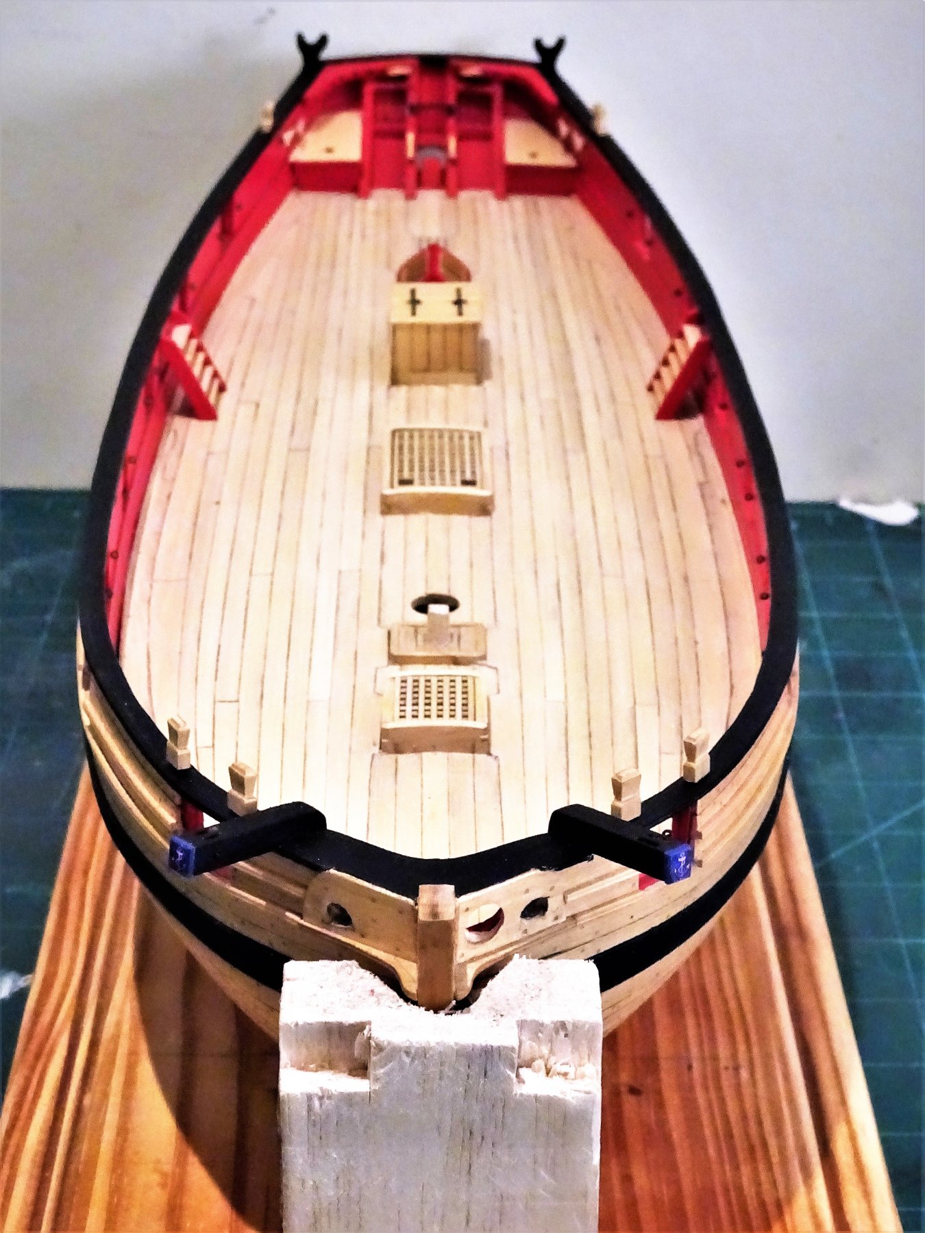
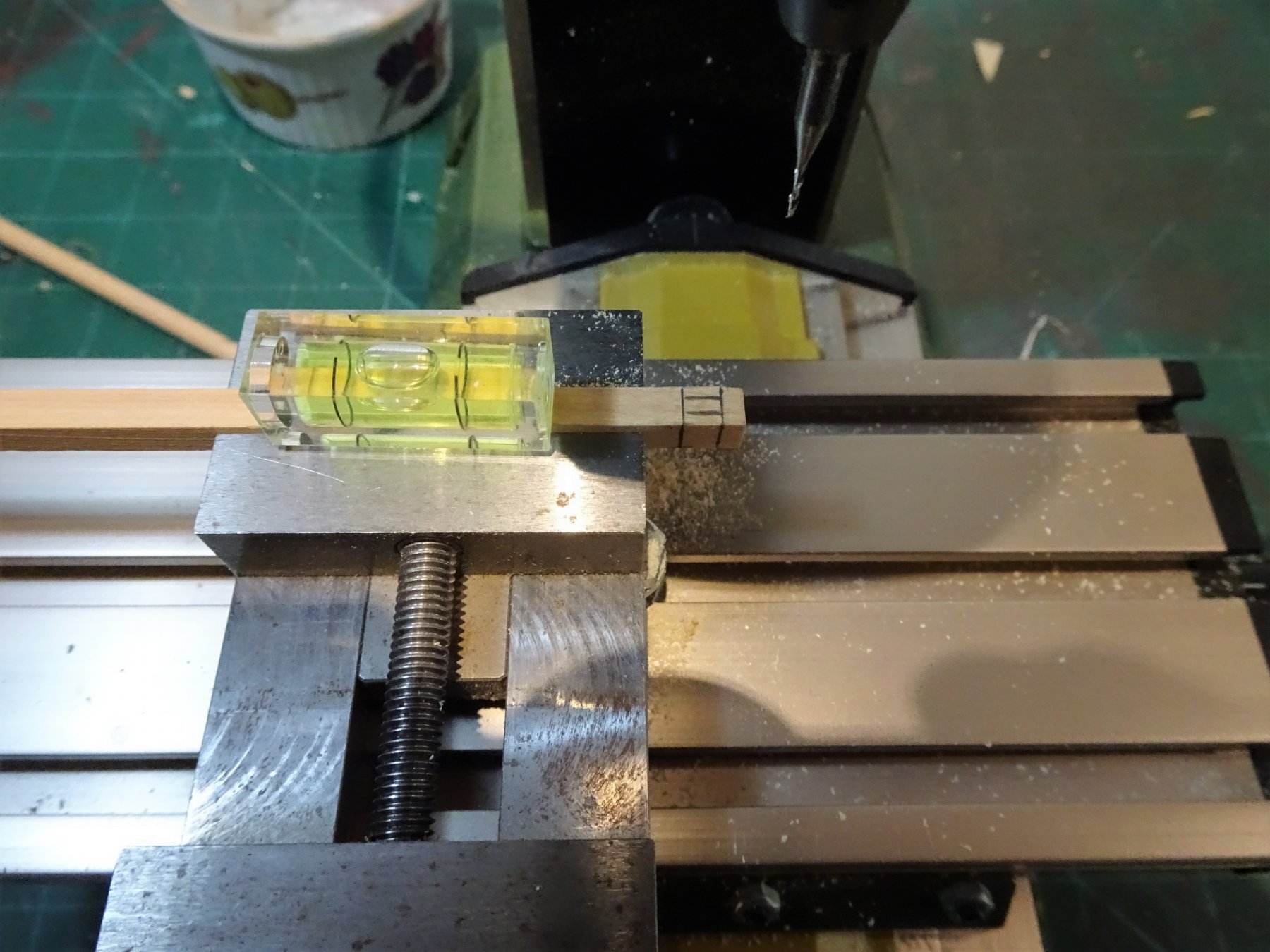
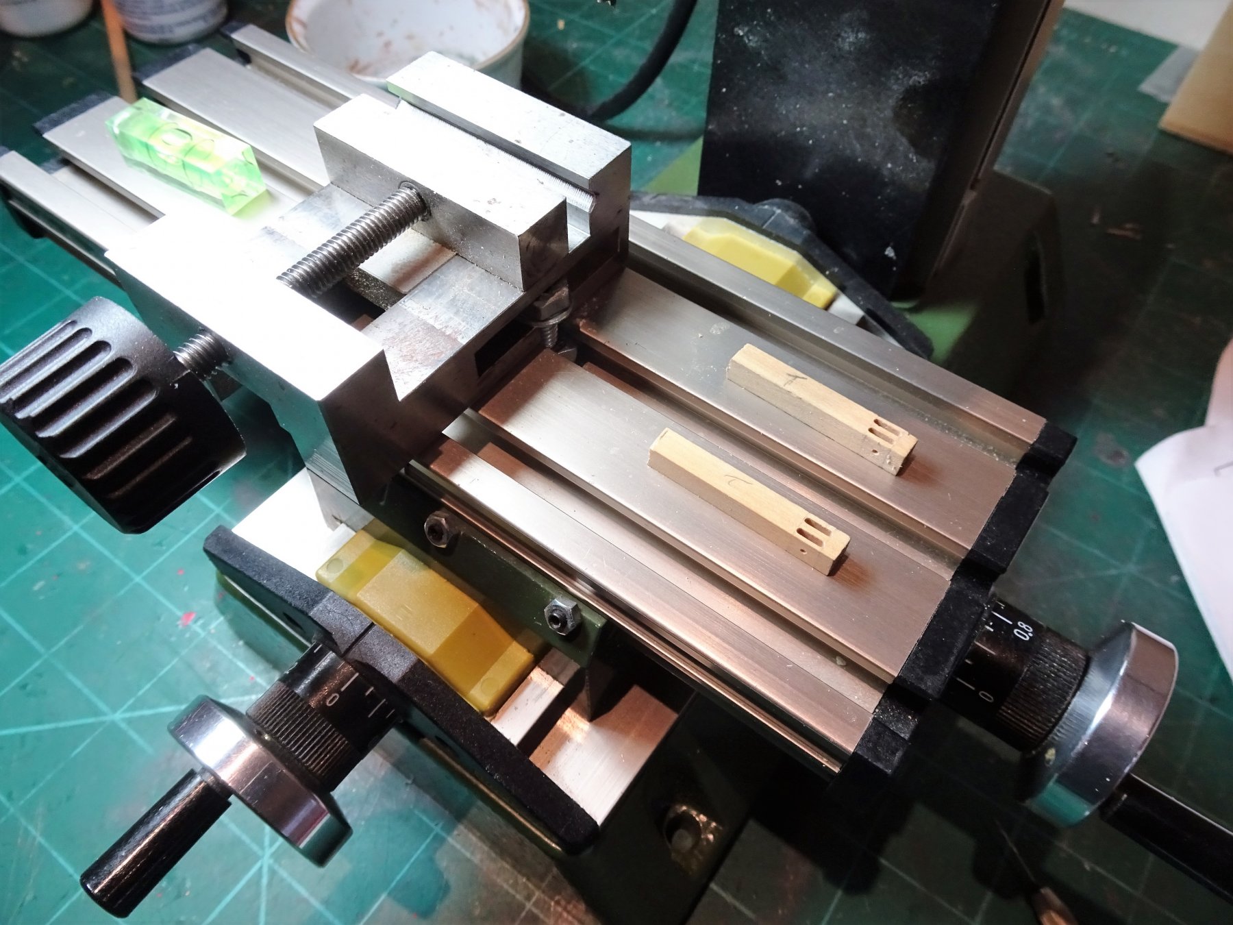
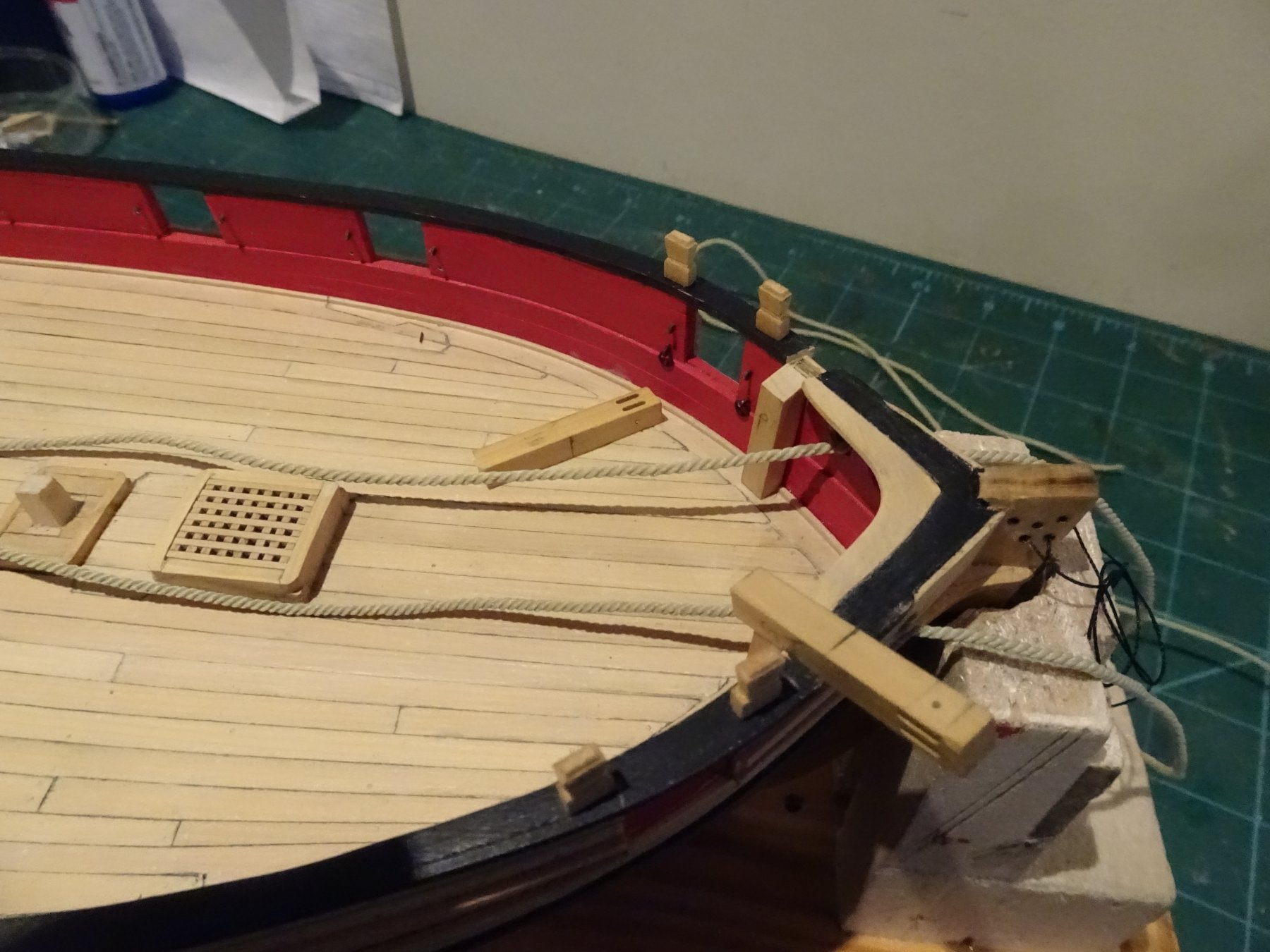
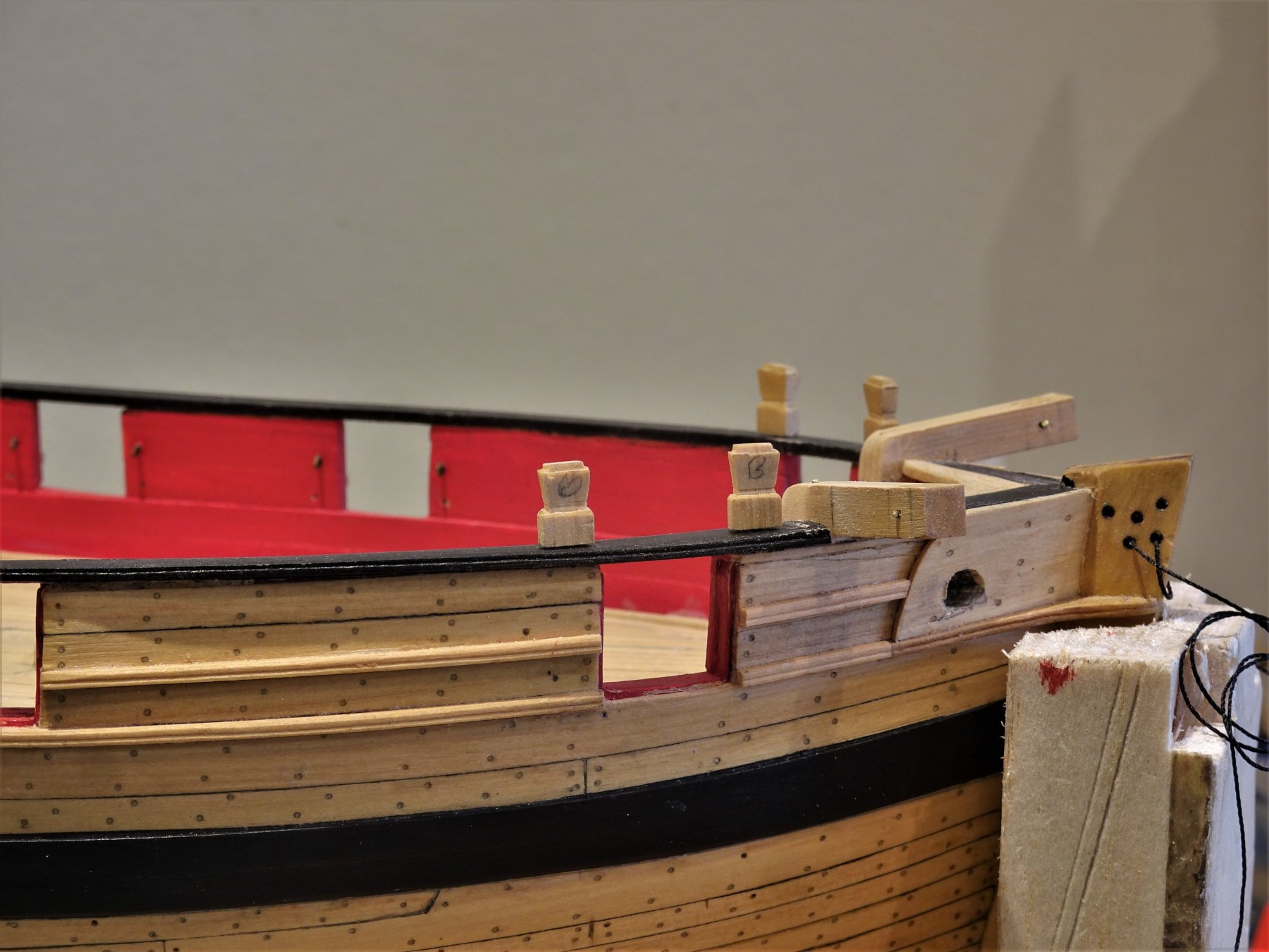
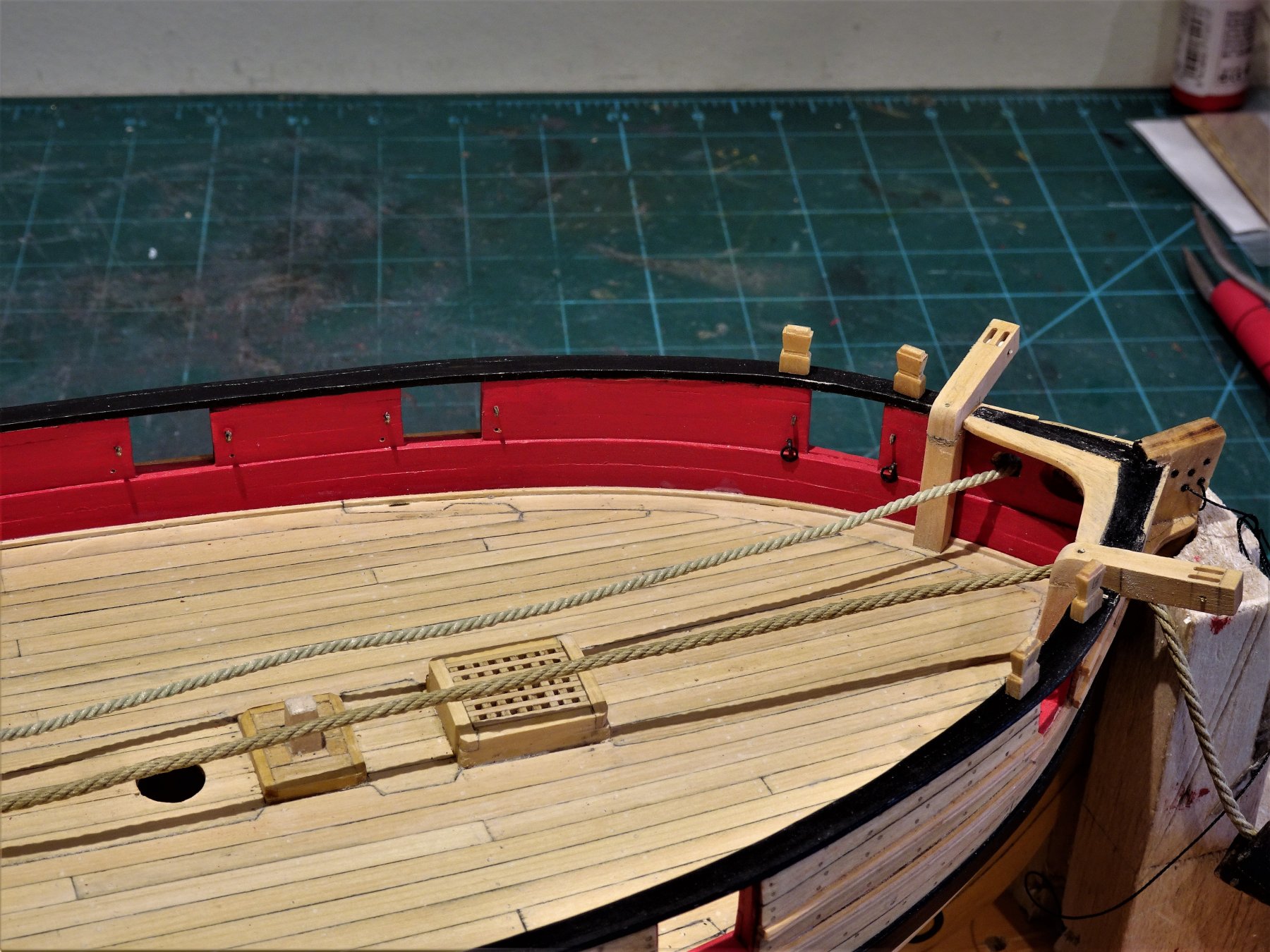
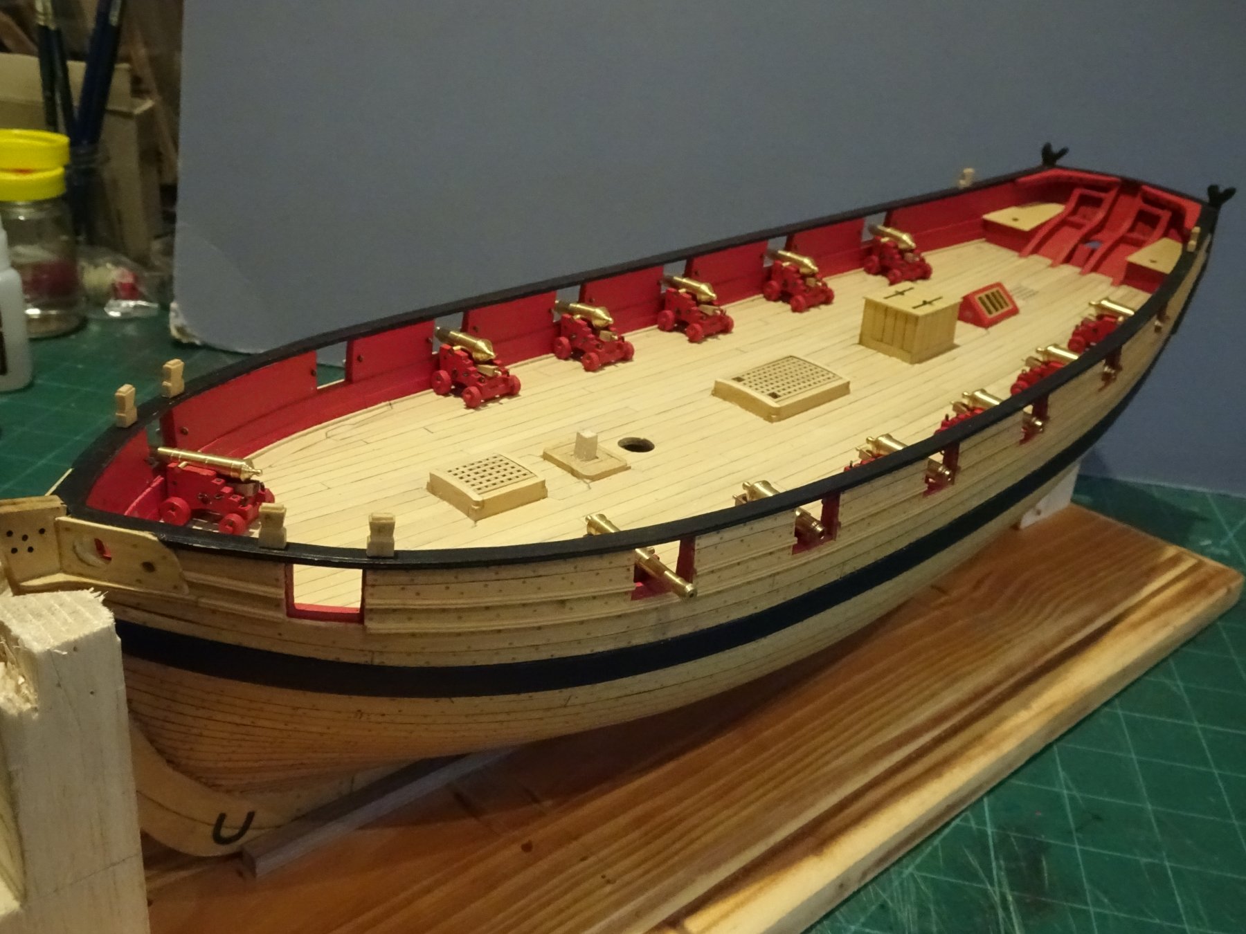
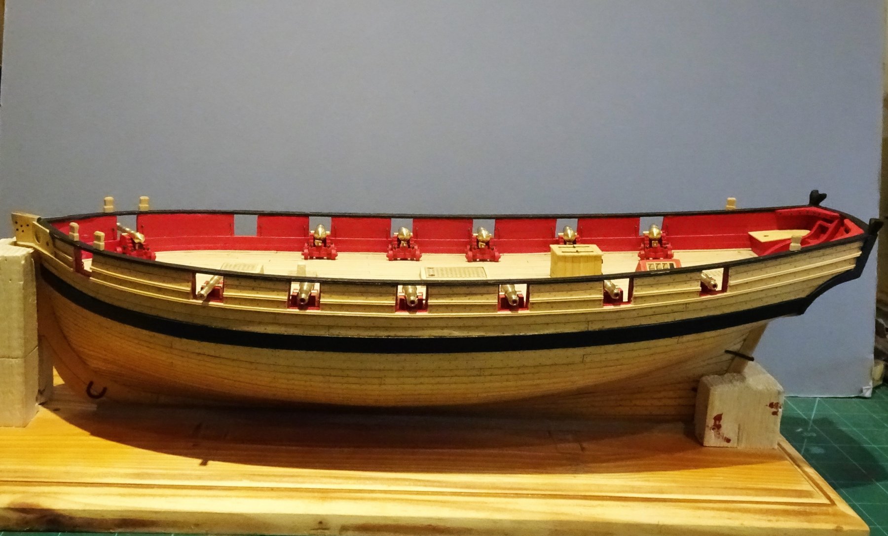
Post 63 Timberheads, cleats, and other sundry attachments Timberheads are fairly easy to carve, getting them all to look pretty much identical is the tricky part. 5693 It is a case of drawing the cut lines and shape on the strip and start carving. 5708 The aft timberheads are slightly more tricky as they have to be shaped at the base to counter the sheer of the rail. I like to use a No 11 scalpel blade fitted in a No3 Swann -Morton handle for this task. The boxwood pares away easily but care has to be taken to control the scalpel. I tend to hold the blade well down the handle, balanced across my forefinger and the scalpel handle end braced against my palm to limit movement. These things were designed to remove tissue and they do it very efficiently as I have in the past found to my cost. 001 Suffering for my art back in 2012 With the stems cut to size a short length of brass rod is inserted into the base to correspond with a matching hole in the cap rail. Cleats. Rather than struggle to make these tiny fittings I opted to use Chuck's pre -made items tweaked to suit. A mixture of 9mm and 7mm sizes. 5710 I also decided at present to leave them natural as a contrast to the inboard paintwork, but in view of my enduring indecision I may revisit this later. Boom Sheet Horse. A specific size for the horse is not given but a piece of copper wire of 1.3mm ø seemed to suit so I used that. The height of the horse is also not specified but the rigging plan shows it in profile and it looks to be around 3mm. 5703 I chemically blackened the horse before fitting. Mine seems to have developed a slight kink, I've previously warned the dockyard mateys about jumping up and down on it, it may have to be replaced. Inboard Ladders I would normally go thro' my parts stock and use pre cut ladder sets, but unfortunately I don't have any close enough to match the Plan requirement. For the ladders I used 3/64" x 5/32" strip. 5594 Copies of the plan ladder profile were glued to the strip and the tread slots marked with a scalpel, and cut using a mini file. It is necessary to take a reversed image of the plan to get the profile for the left hand stile slots. Always tricky little beggars to assemble, they seem to have a life of their own and the stiles do need simple jigs to hold them steady whilst the treads are inserted and the opposing stile is attached. 5684 I decided to leave the treads natural. 5707 5690 Pin Racks One each of these is positioned along the bulwark adjacent to the mast. Simple to make from 3/64" x 3/16" strip which allows for the slight curvature along the edges. 5733 Brass pins were inserted in the back edges to provide extra support when glued to the bulwark. B.E. 30/01/2019


.thumb.JPG.2406edc811025780ce462960e3524c79.JPG)

- 574 replies
-
- 22
-
-
- cheerful
- Syren Ship Model Company
- (and 1 more)
-
Very nice work on those guns Jason, I got off lightly having only a dozen on my little Cutter. Love the natural drape you’ve achieved on the breeching ropes , and impressed that you went with the proper hitch for the ring bolt seizing. Your little jig for rope length will prove useful for me in the very near future. B.E.
-
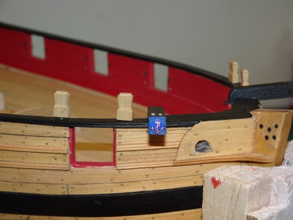
Post 62 Completing the Catheads These are now painted and the cleats attached. 5697 Working sheaves are in place, and I decided to add a decorative panel at the end which on the real thing also served the purpose of protecting the end grain of the Cathead. 5673 5691 Catheads were traditionally decorated and apparently around the beginning of the 19th c a *fouled anchor was in vogue. *The Construction and Fitting of the English Man of War 1650 - 1850 by Peter Goodwin. No evidence what decoration, if any, Cheerful had on her Cathead, but the idea of a fouled anchor appealed to my sense of irony, so a fouled anchor it is. 5700 Not a fancy carved version as might appear on a more important vessel, but a simple painted affair more appropriate to a humble cutter. Inboard works continue in my next post. B.E. 28/01/2019


- 574 replies
-
- 14
-
-
- cheerful
- Syren Ship Model Company
- (and 1 more)
-
Thank you Jnugid, much appreciated. 🙂 Hi Dave, I think 1.8mm ø line should be about right. I don't intend to fit a cathead bracket, but Peter Goodwin shows one on the Alert book plans and drawings. Hi Martin, The method of constructing the Cathead on the Cheerful is a modelmakers simplification as used by Chuck. I think the idea is you shouldn't see the join. Hopefully by the time I've completed the painting it won't be apparent on mine either. The alternative and more authentic method would be to cut the Cathead from a single piece of timber, but then it would be more tricky to cut the sheaves in the outboard end. In reality small vessels like Cheerful would have had what was described as a vertical Cathead, cut from a selected piece of compass timber shaped and bolted thro' the bulwark. Cutters carried fairly lightweight anchors of around 18cwt, so the method was considered adequate for the task. Thanks Jason, I didn't use a jig for the timberheads, these will be the subject of my next post. Cheers Guys. B.E.
- 574 replies
-
- 2
-
-
- cheerful
- Syren Ship Model Company
- (and 1 more)
-
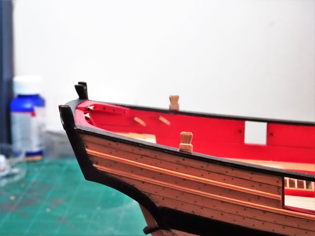
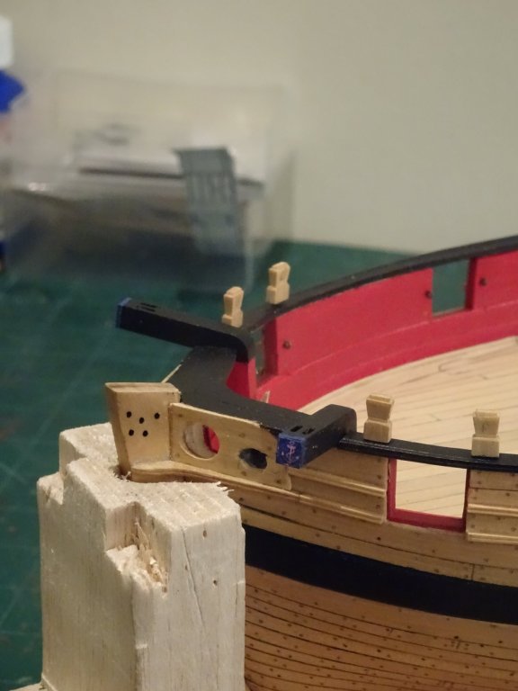
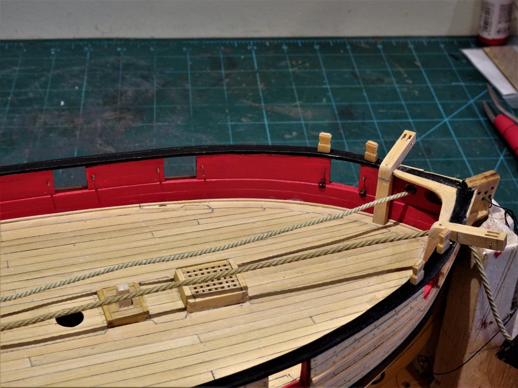
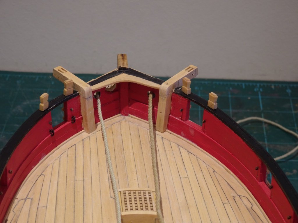
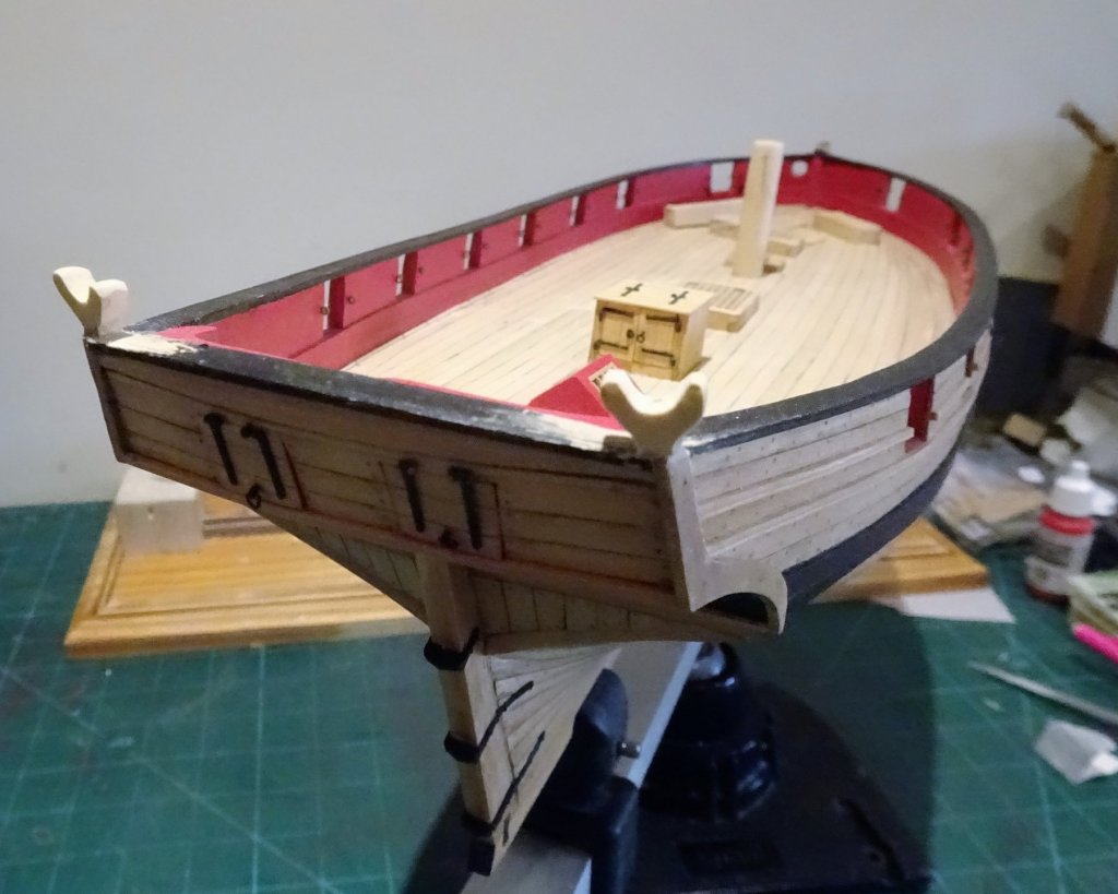
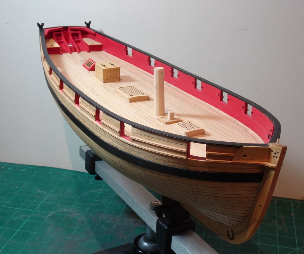
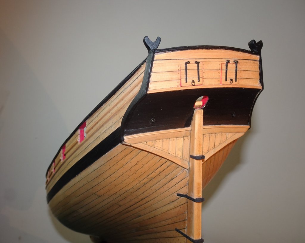
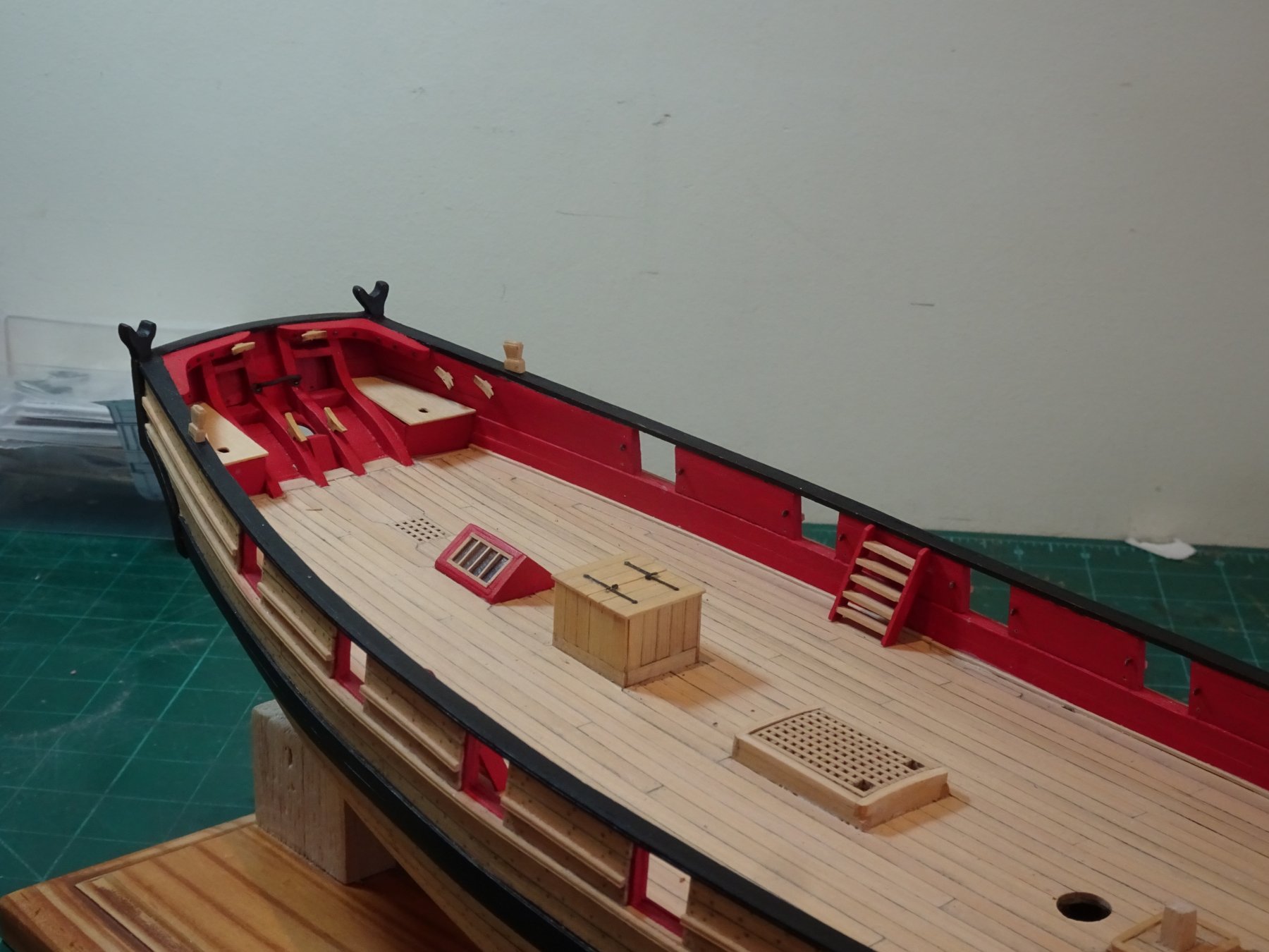
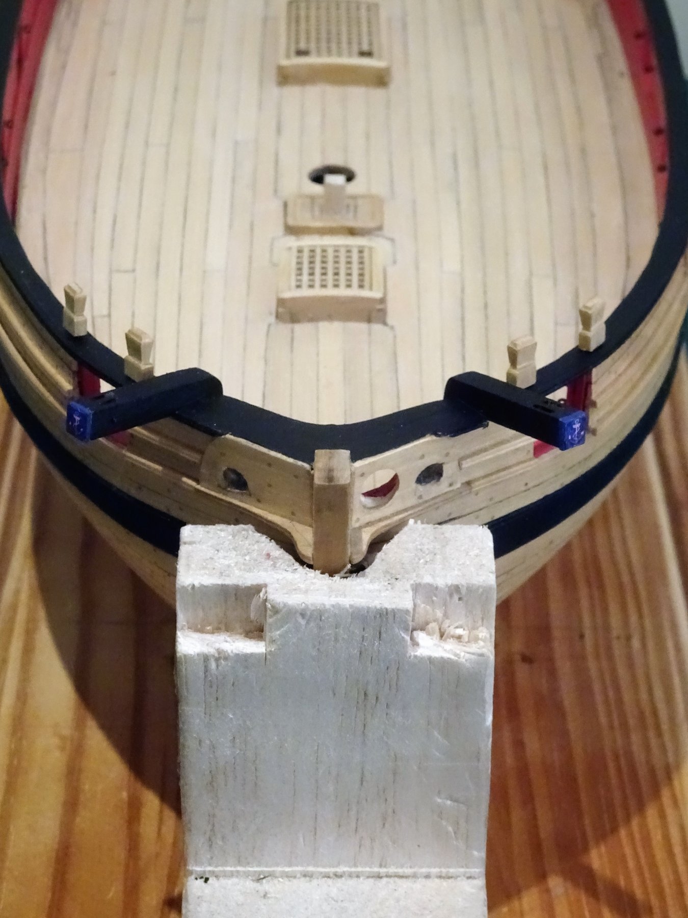
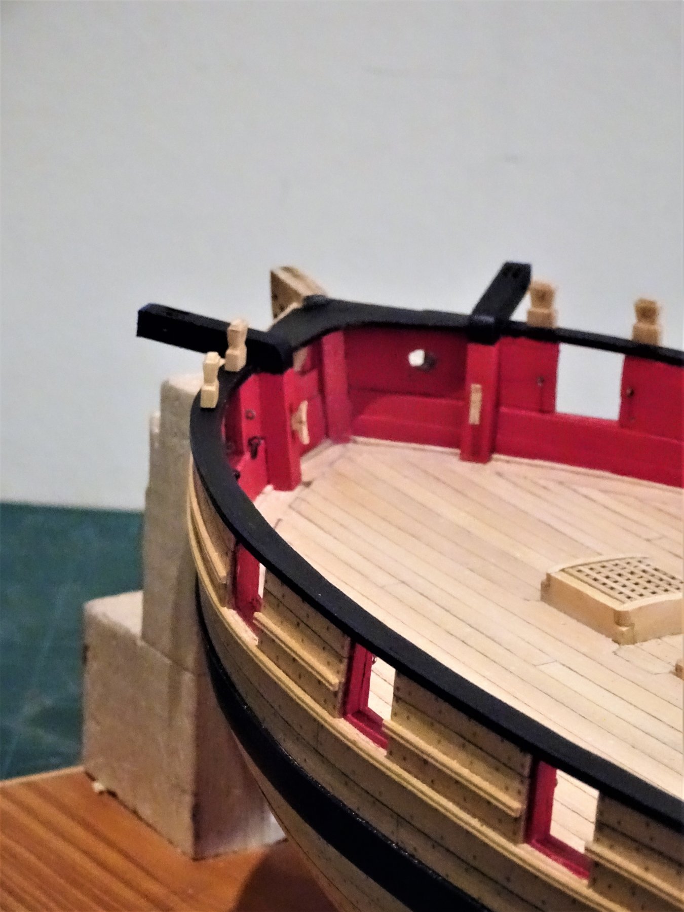
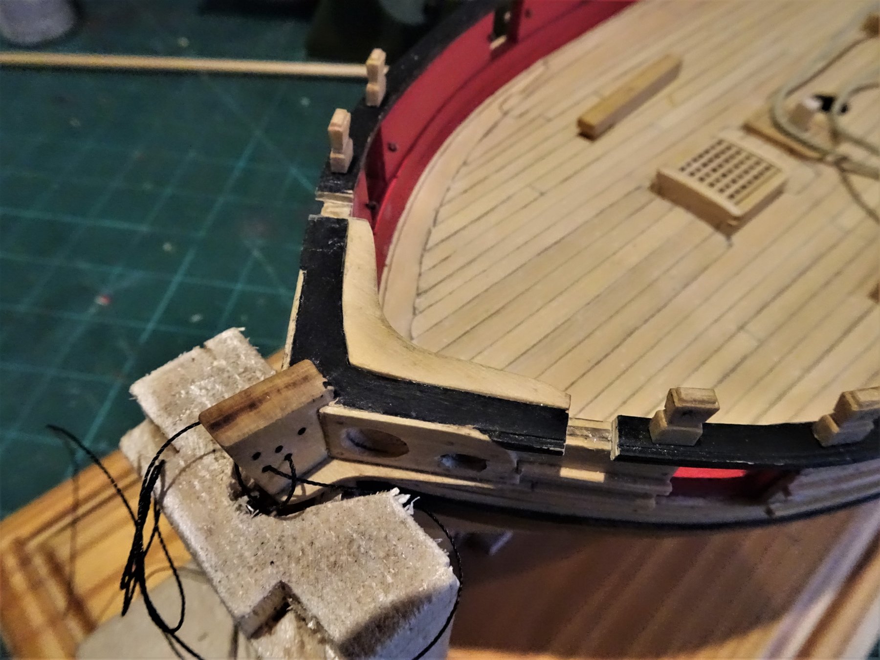
Post 61 Hawse Holes, cables, and Catheads. At this point there is a lot of inter-related stuff to consider. 1) I intend to rig anchor cables, so I need to establish the size. 2) I also need to enlarge previously drilled undersized hawse holes at the bow and the hawse holes sizes are relative to the circumference of the anchor cables. 3) A check needs to be made that the anchor cables will have a clear run from the hawse around the windlass, and back to the Main Hatch without fouling the Catheads yet to be fitted. Firstly Anchor cables Calculating anchor cable sizes can be a confusing subject. According to Lees the formula for anchor cable circumference calculation is 0.62 of Mainmast diameter. Peter Goodwin - The Naval Cutter Alert 1777 gives 11½" as the main cable circumference (1.93mm ø at 1:48 scale) He also gives the Mainmast ø as 22", which using the Lees formula would give a cable of 13.64" circ. (2.29mm at 1:48 scale) There is another formula based on the maximum beam of a vessel. - Cable Circumference being ½" for each foot of beam. Using the Alert figures we have a beam of 25'.11" which would give a cable circumference of 12.95" (2.18mm ø at 1:48 scale) So from a given set of reference figures you do get variances using the different formulas, but in modelling terms the differences are minor, and in practice the dockyards worked to range sizes, and the nearest fit was generally close enough. In relation to Cheerful the mast at the partners (model) is 10mm ø ( x 0.62 (Lees formula)) = 1.97mm ø line. Using the beam formula; Cheerful, with a beam of 23.5' would give 11.75"circ also = 1.97mm at 1:48 scale. Having eventually arrived at a scale anchor cable diameter, we can return to the Hawse hole. *To calculate the hawse hole size:- cable ø ÷9/4 = hawse ø *Construction and fitting of The English Man of War - Peter Goodwin I used incremental drill sizes to carefully enlarge the Hawse holes ensuring the drill was kept both horizontal and parallel to the keel. In considering cable sizes on models I don't think that arithmetically calculated scale line sizes are the whole story, Sometimes, 'true scale' doesn't suit the eye or model. 2mm ø line looked a little heavy, particularly bearing in mind that it will have to pass around the windlass three times. I am leaning towards 1.75mm ø line for the anchor cables which equates to a 10.3" circumference, and looks right to my eye. The calculated hawse ø scales to 3.93mm. This is pretty much the hawse ø given on the Cheerful plans. The related positions of the Windlass, Bowsprit, Bowsprit step, catheads, winch, and cables need to be assessed to avoid problems later. 5541 With the cables in place the Cathead positions can be tweaked to avoid any awkward abrasions. Before I do any further work I attended to the bow pin rack which butts against the Catheads each side. 5544 Bearing in mind that there may be an issue with belay pins where the Bowsprit passes beneath the rack I have held off drilling the holes until later. In making the Catheads I have followed Chuck's lead using 3/16th square boxwood section. 5548 The rebates to fit over the waterway and spirketing on the vertical sections of the Cathead were initially cut on the little mill, but to get the inboard shape to scribe closely to the bulwark took a fair bit of manual work with scalpel and sanding stick. The base needed sanding at an angle to sit flush on the margin plank. 5550 The sheaves for the outer end were cut on the little Proxxon mill using a 1mm bit, and holes were drilled to take the sheave pins. 5551 5552 Assembling and fitting the Catheads I found a little tricky. The Cathead should have something of a stive, angling slightly upwards outboard. 5569 This means that either the vertical section or the inboard tail of the outboard section needs to be angled. I decided to angle the uprights. Once I had got close to the angle required I glued the upright to the bulwark. 5590 The outboard section was then roughly shaped at the inboard end and glued and pinned, with final sanding done insitu. 5591 The Catheads in their raw state Here you can see a comparison of 2mm line (Starboard) and 1.75mm line (Port) 5587 I was a little surprised that a supporting bracket below the outboard cathead beam was not present on Cheerful. B.E. 25/01/2019

- 574 replies
-
- 22
-
-
- cheerful
- Syren Ship Model Company
- (and 1 more)
-
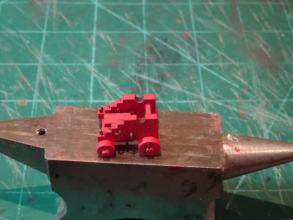
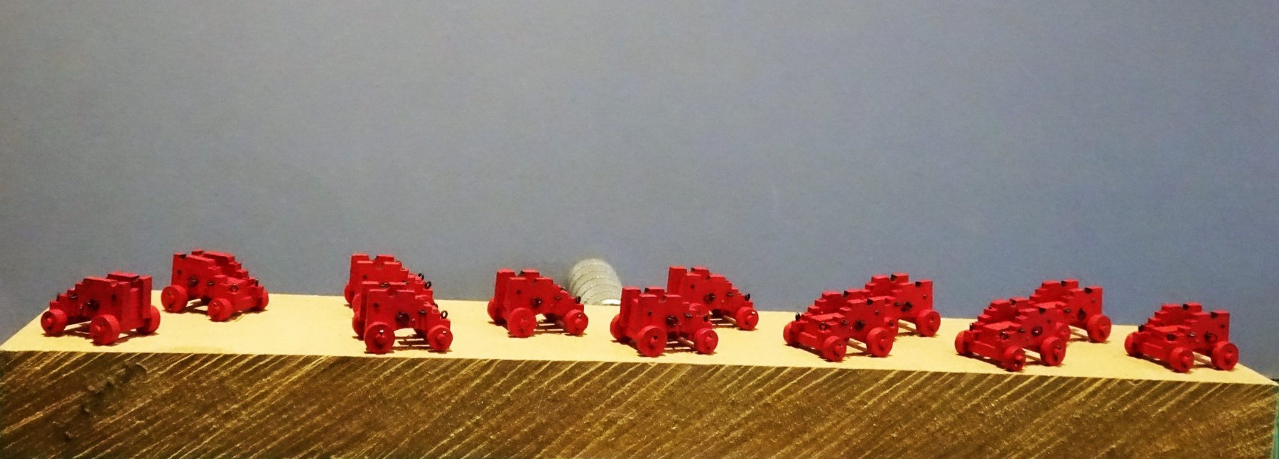
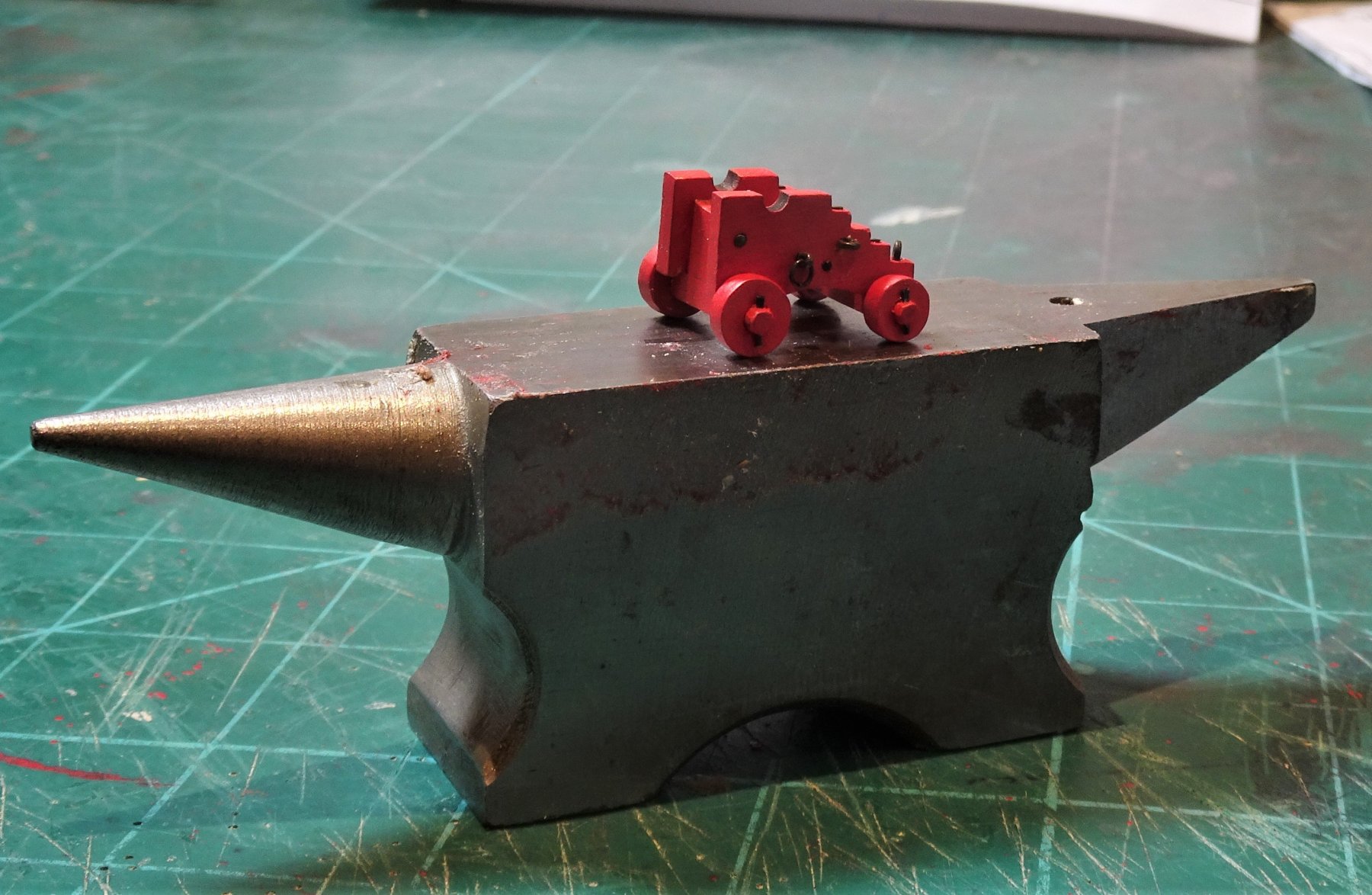
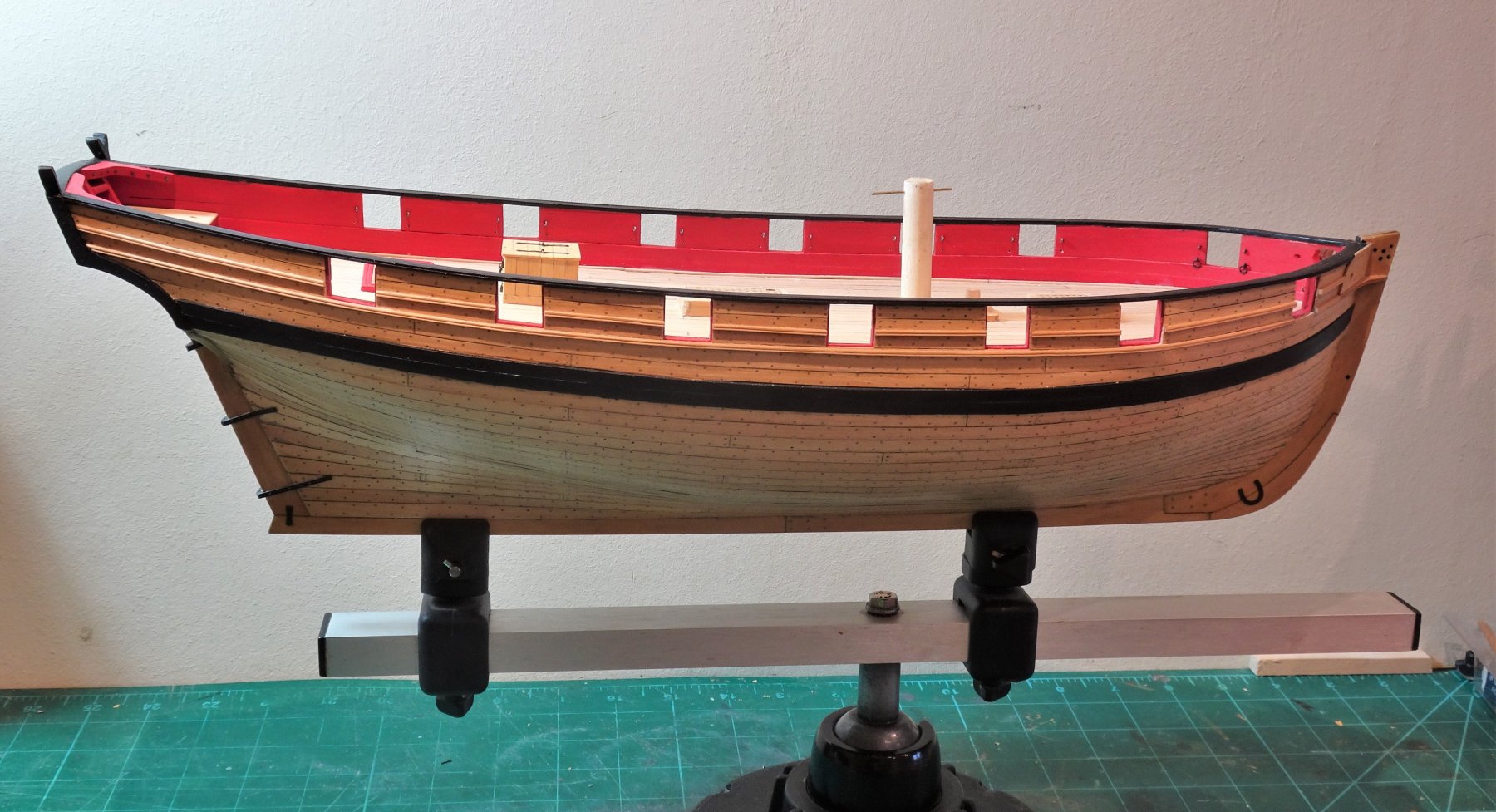
Hi bcd, yes the official colour for inboard works including the gun carriages was Red Ochre. This applied from the 17th century thro’ to the early 19th century. However, during the late 18th c Yellow Ochre became increasingly popular, initially unofficially, and some Captains authorised the repainting of the carriages which were the usual dockyard red. By 1806 I would have expected most inboard works to be Yellow Ochre, but for a small unrated vessel such as a cutter it would be the cheapest option, and still at that time the Official colour. This is the short simplified explanation. 😊 Cheers, B.E.
- 574 replies
-
- 4
-
-
- cheerful
- Syren Ship Model Company
- (and 1 more)
-
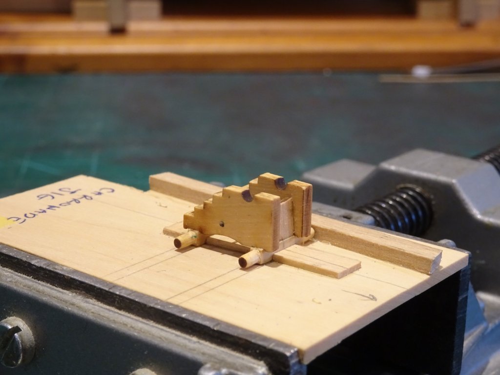
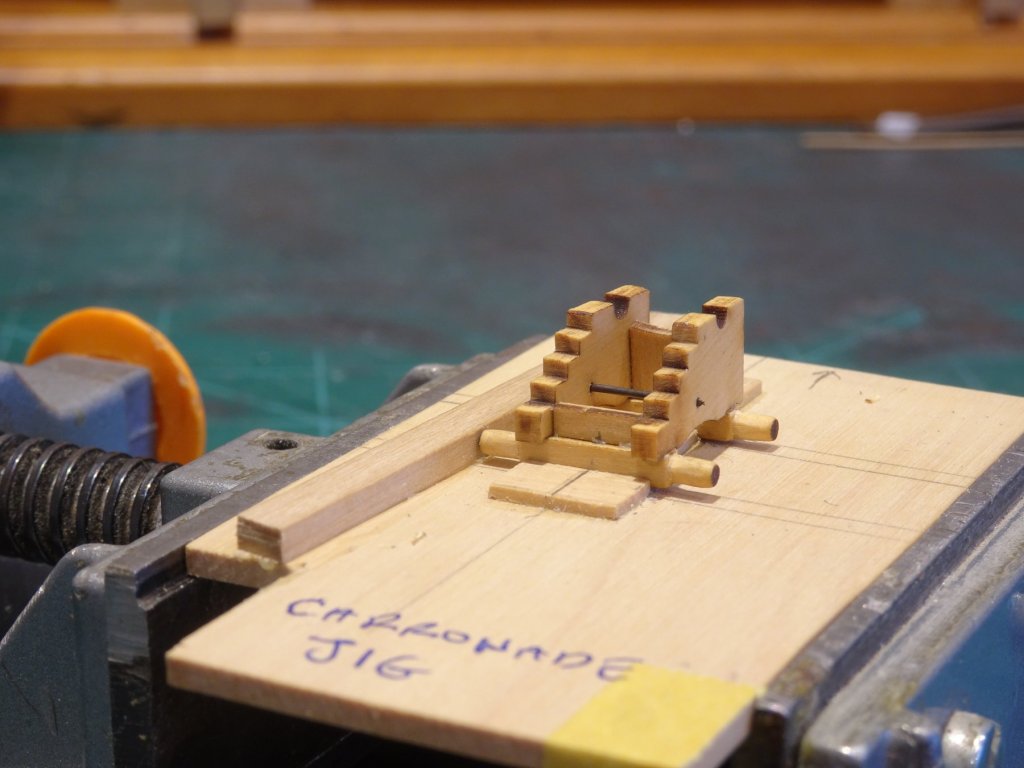
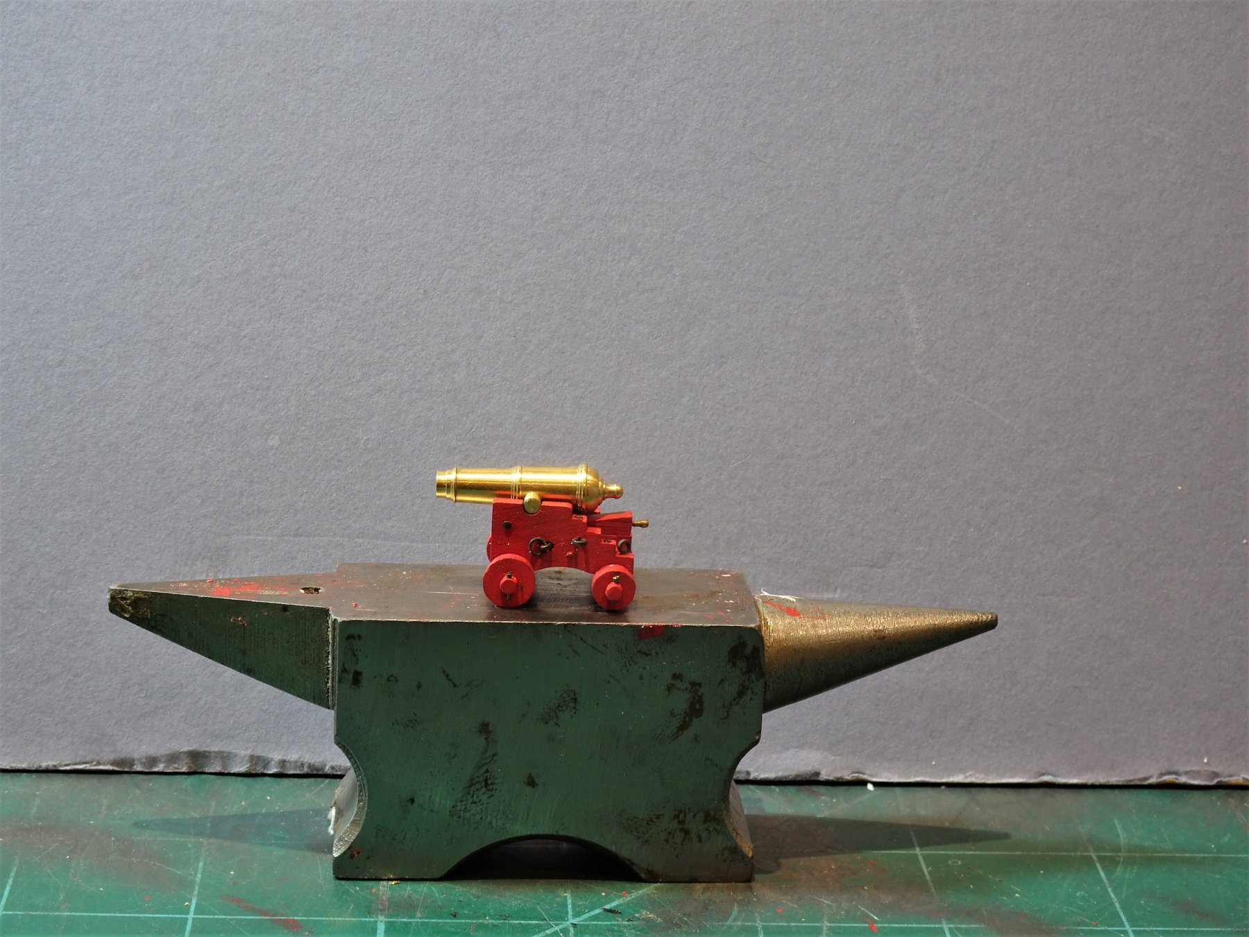
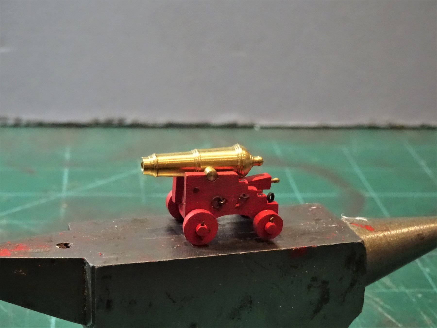
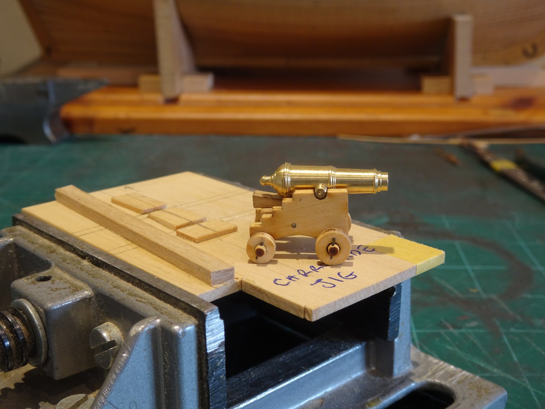
Thanks Jason, The Carronade carriages are 20mm long x 7mm wide x 12mm high plus the trucks. For the tackle rings (hoops) I create an elongated countersink by simply angling the micro drill from the sides of the holes to produce a slight groove which allows the eyebolt to sit deeper. Regards, B.E.
- 574 replies
-
- 1
-
-
- cheerful
- Syren Ship Model Company
- (and 1 more)
-
Cheers Dave, Peter Goodwin in his Naval Cutter Alert book gives the anchor cable size as 11½" circumference which equates to 1.9mm ø line at our scale. Alert was of greater tonnage than Cheerful, so the cable size would be slightly less. I'll dig into my sources to confirm the formula, cables will be the subject of my next post. B.E.
- 574 replies
-
- 1
-
-
- cheerful
- Syren Ship Model Company
- (and 1 more)
-
On the Syren web site which Chuck operates, there are a series of build guides for different models that he produces, Cheerful being one of them. He also has a build log of his own Cheerful build which is also a mine of information. Well worth a visit. ☺️ B.E.
-
Thank you Wallace, there are many unusual terms and words we come across whilst living in the nautical 18th century.😉 That the guns all look identical, is more down to the skill of Chuck and his laser cut parts I think.🙂 Hi Martin, I too thought the Carronade carriage design was a little unusual as I expected a sliding bed and traversing trucks at this time. However, Chuck had looked into this and the wheeled carriage was not unusual particularly on smaller vessels. There is a plan of such a set up in the NMM. That's a very handsome offer Dave, I will pm you.👍 As a matter of interest what size line did you use for your anchor cables, I note that Chuck makes no reference to them in his guides. Thank you Thomas, - and not finished yet! but I'm relieved to have got thro' the bulk of it. … and thanks for all the 'likes' guys who have looked in on the build. B.E.
- 574 replies
-
- 1
-
-
- cheerful
- Syren Ship Model Company
- (and 1 more)
-
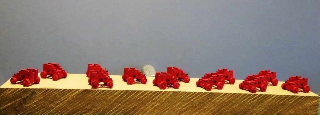
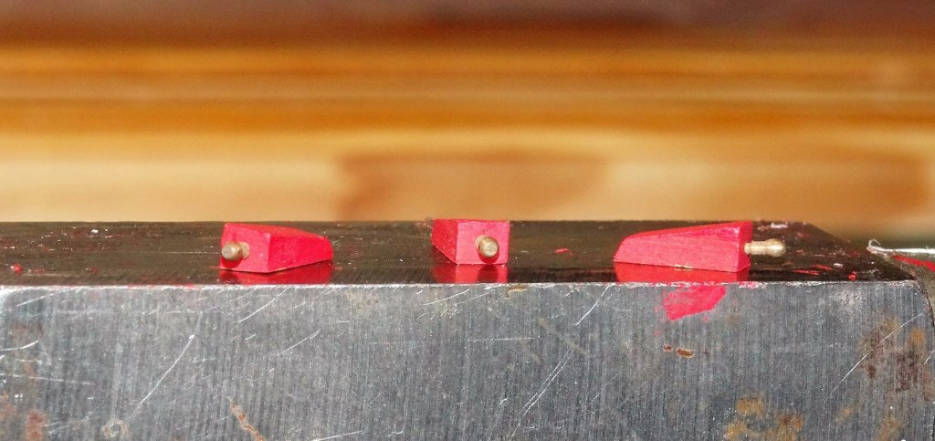
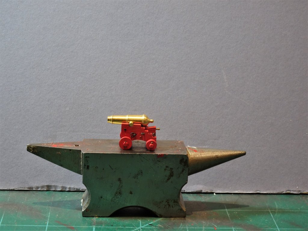
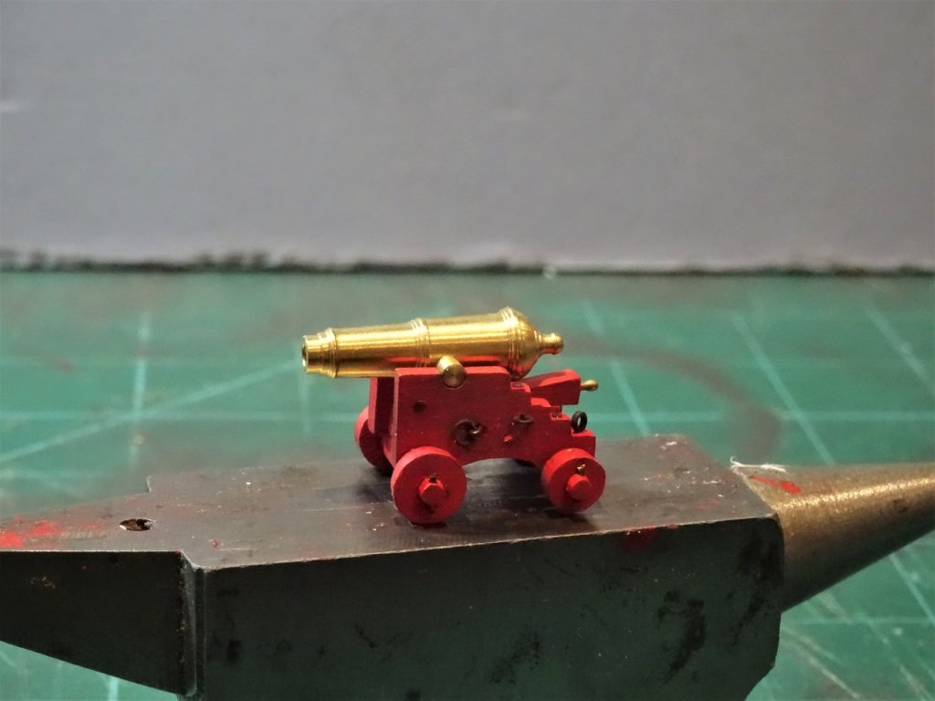
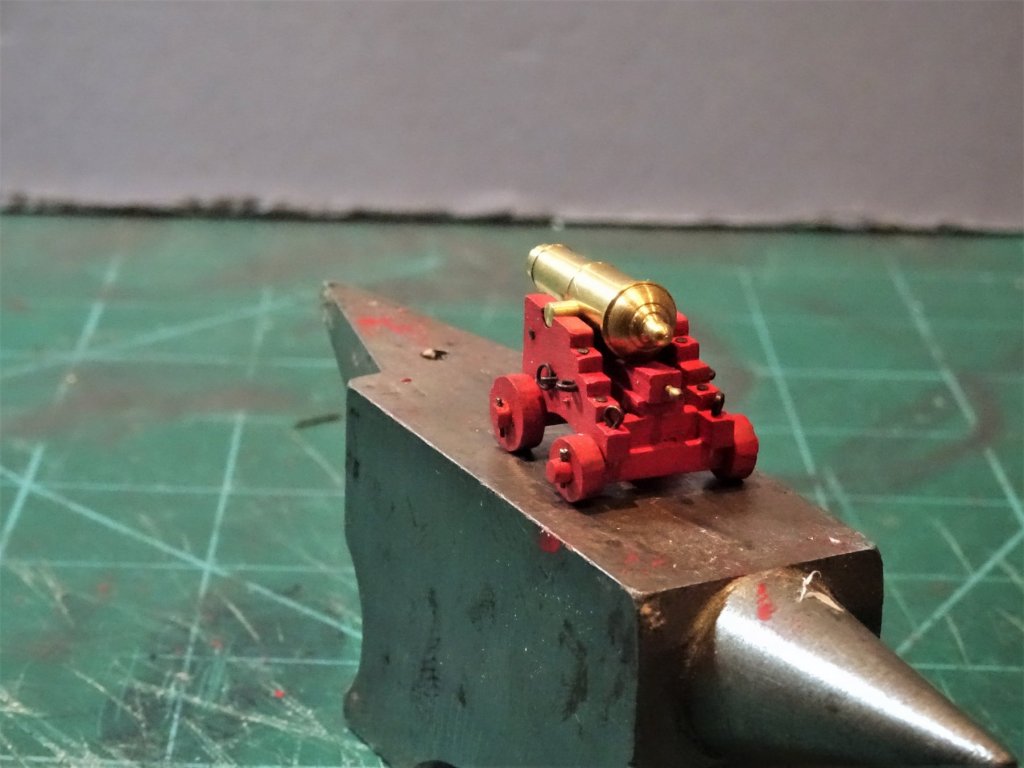
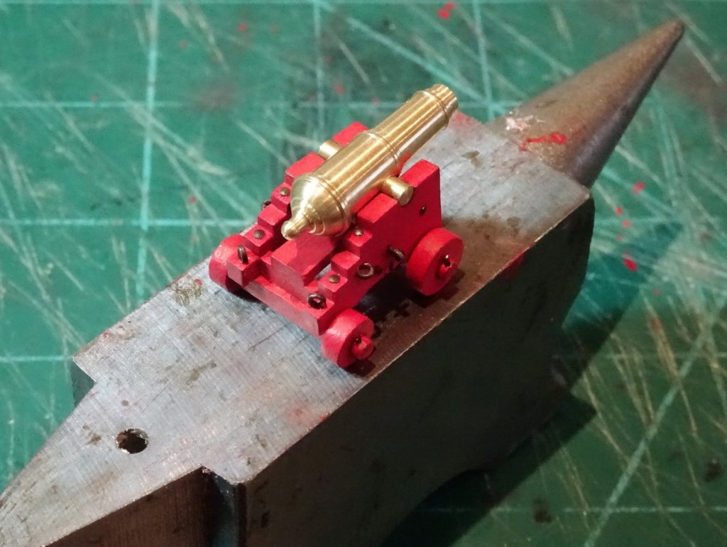
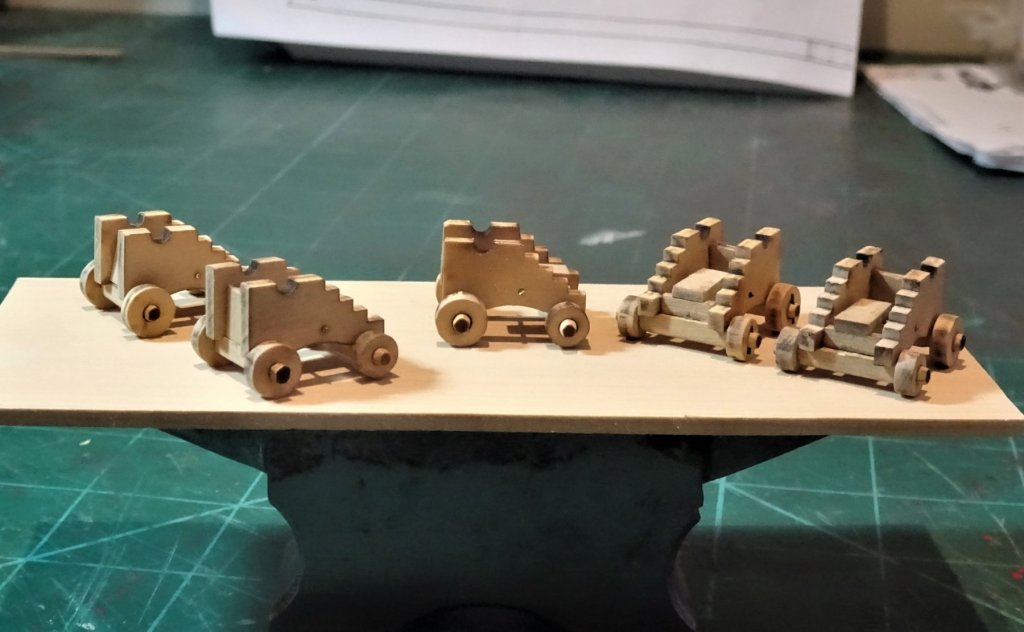
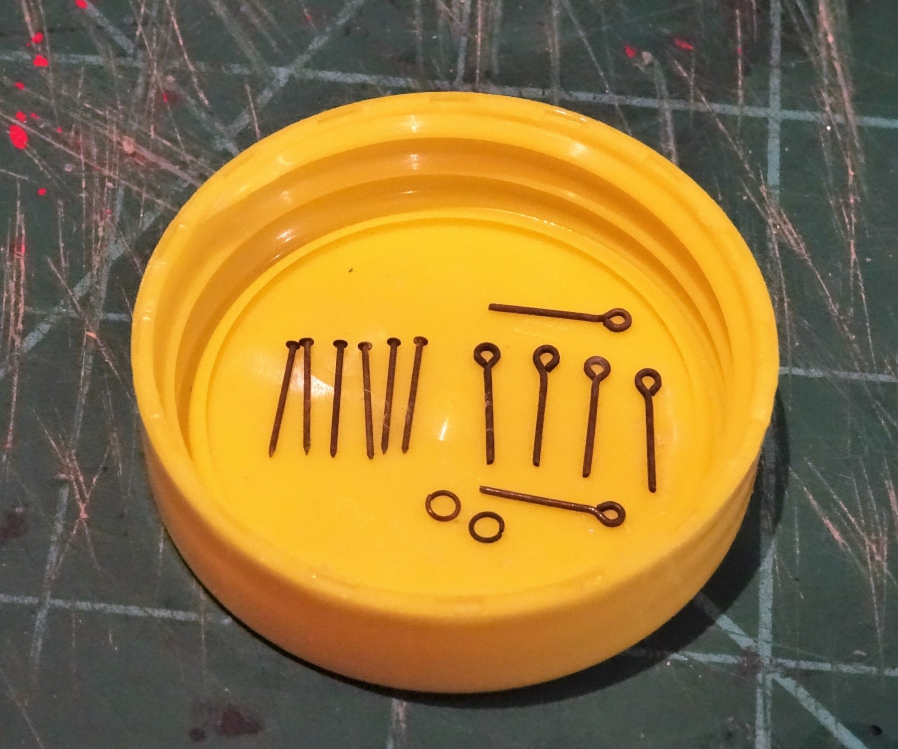
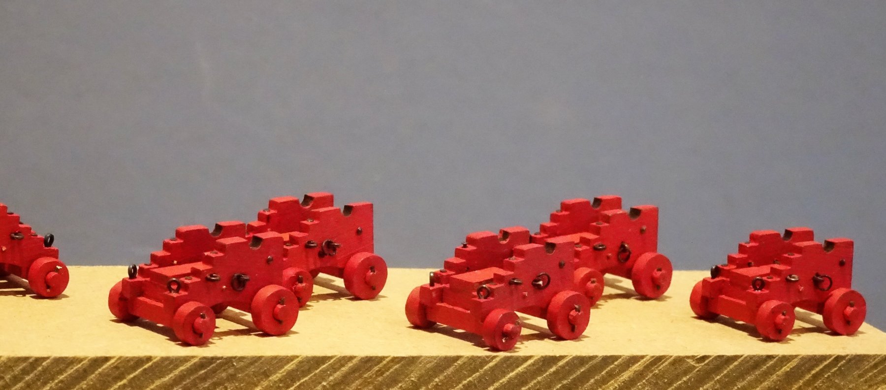
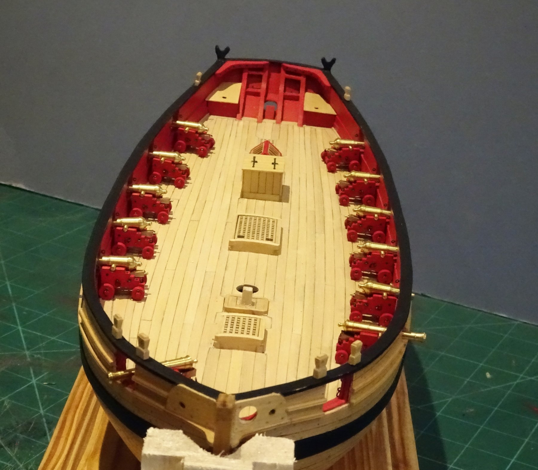
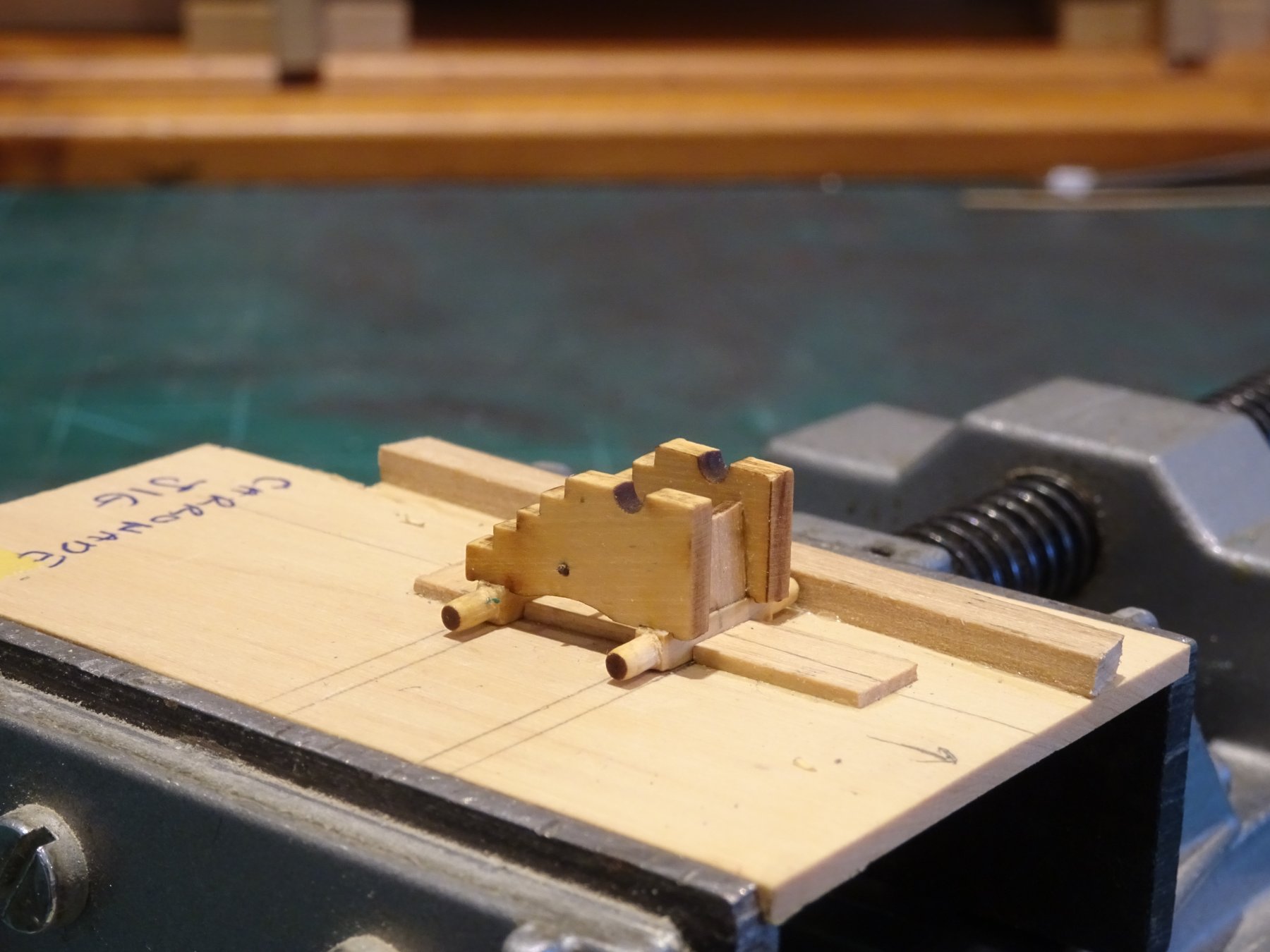
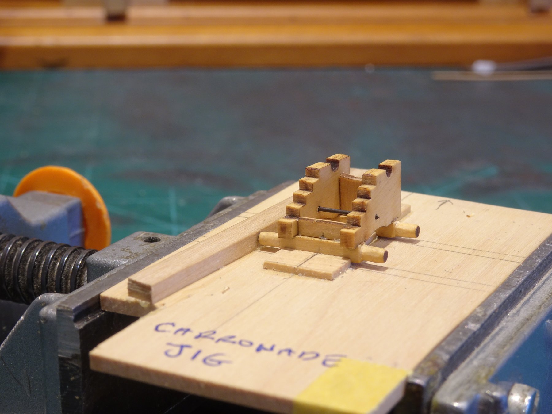
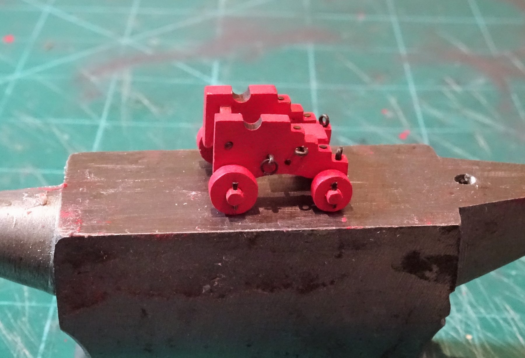
Thanks Thomas and Rusty, I surely am glad there's only 12 guns on Cheerful, even so they are big enough to warrant full detailing and all are exposed to full view. Post 60 Completing the carriages. Work proceeds on the carriage assembly line. Making the fittings is a time consuming exercise, the fittings are small and take every opportunity to wing off into the ether never to be seen again. Regular crawling session around the carpet is part of this process. 5368 The fittings required for each carriage consists of: 6 pins to represent the bolts. 4 eyebolts ( tackle attachment hoops) 2 ringbolts comprising a modified eyebolt plus ring( Breeching line) 4 truck keys to retain the trucks on the axles. OK these were not included in the original plans but I like to fit 'em, and at least in this case the trucks were solid and not held together by six bolts. On completion of the Carronade carriages I assembled the long gun six pounder equivalents. I was able to utilise the carronade jig for assembly, but the procedure is effectively the same. So after nine days, which felt like twice the time, the carriages are completed bar a bit of fettlin'. 5461 Even so there are still things to do once the barrels are fitted: 2 capsquares to retain the carronade trunnions 2 capsquare hinges ( modified eyebolts) 1 capsquare locking pin plus retaining chain. I added these on my 1:64 scale Pegasus guns, so at 1:48 scale it should be easier. 5464 On this shot the truck keys are evident, made from the fine brass pin stems flattened at one end. The Breeching line ring bolts are only temporarily in place for the purpose of the photo. At this point I do a deck fit to check how the quoins may affect the barrel line along the hull. 5468 5475 It seems that in the normal position the quoins are a tad fat to allow the barrel to sit horizontally thro' the port. 5469 5477 For the quoin handles I passed on trying to make them from wood. 5482(2) Fortunately Amati 5mm brass belaying pins fit the bill perfectly. 5487 5491 5492 I will now put the ordnance aside for a while to concentrate on completing other fittings. B.E. 20/01/2019


.thumb.JPG.b2f84ab0aabcf9b74b298da6e0e8e7cf.JPG)
- 574 replies
-
- 20
-
-
- cheerful
- Syren Ship Model Company
- (and 1 more)
-
Beginning to look more like silk purse than pigs ear now Thunder.🙂 There is a certain satisfaction to be had from working around a kits deficiencies. B.E.
- 102 replies
-
- 1
-
-
- cruiser
- caldercraft
- (and 1 more)
-
Thanks Wallace, it is nice to have a hard copy album of build progress photo's to flick thro' rather than sit at the desk top.☺️ B.E.
-
You're right Doug, they do look neater running the direct route, mine rest against the Backstays but I suppose the ship is not usually in motion with bare sticks, and any friction is minimal. B.E.
-
Looking good Doug, good idea not to belay those sheet and tack lines too soon. One thing I would mention the sheets and tacks should run outside of all the standing rigging. If you visualise when working, the sheets and tacks attach to the outer lower corners of the sails, well outboard of the confines of the ship. The sheets would not be able to work if they ran inside of the backstays. B.E.
-
Hi Derek, Here's the link to the supplier I use. http://www.just-bases.co.uk/?page_id=135 Paul has made several cases for my ship models both small and large, and I've always been pleased with his cases. Cheers, B.E.
-
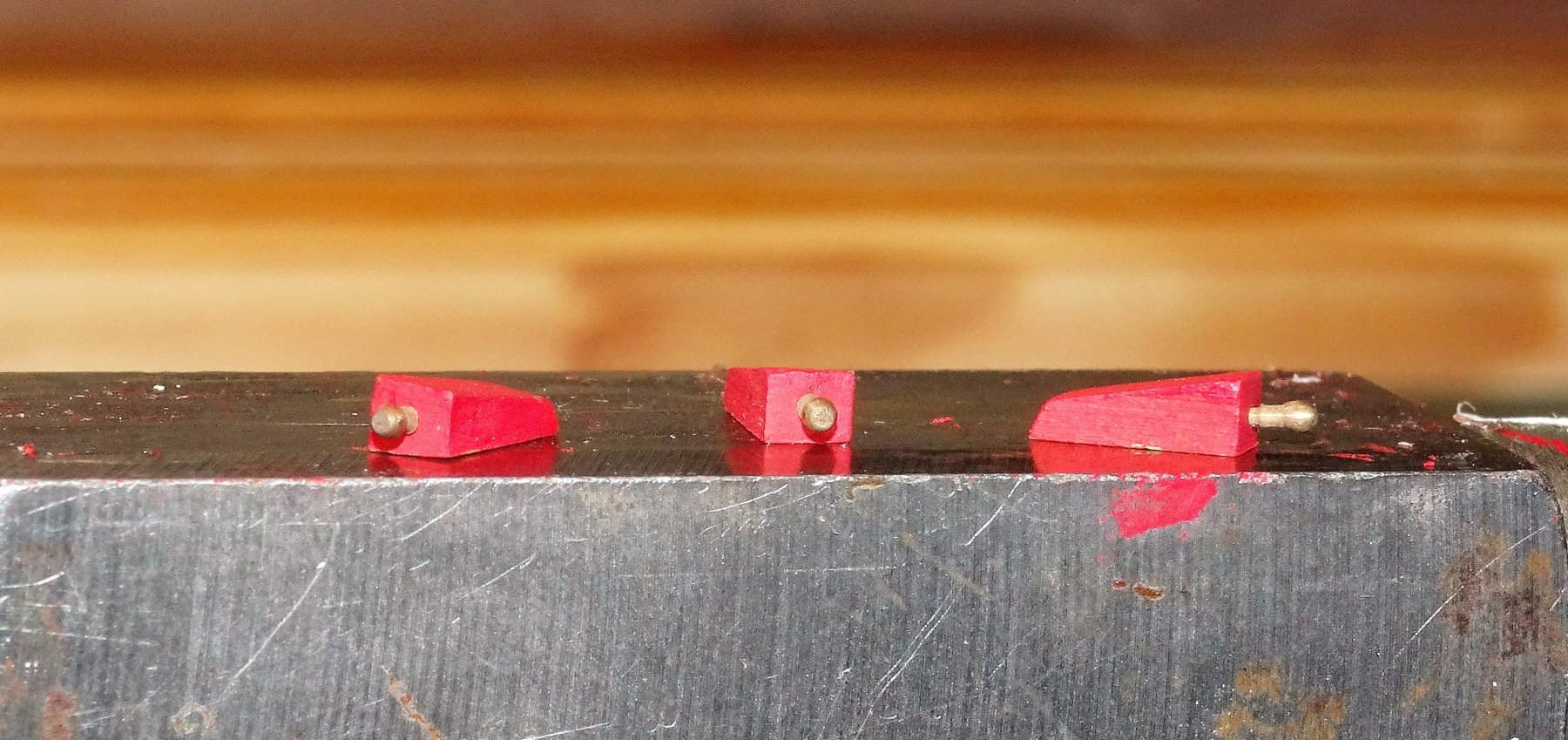
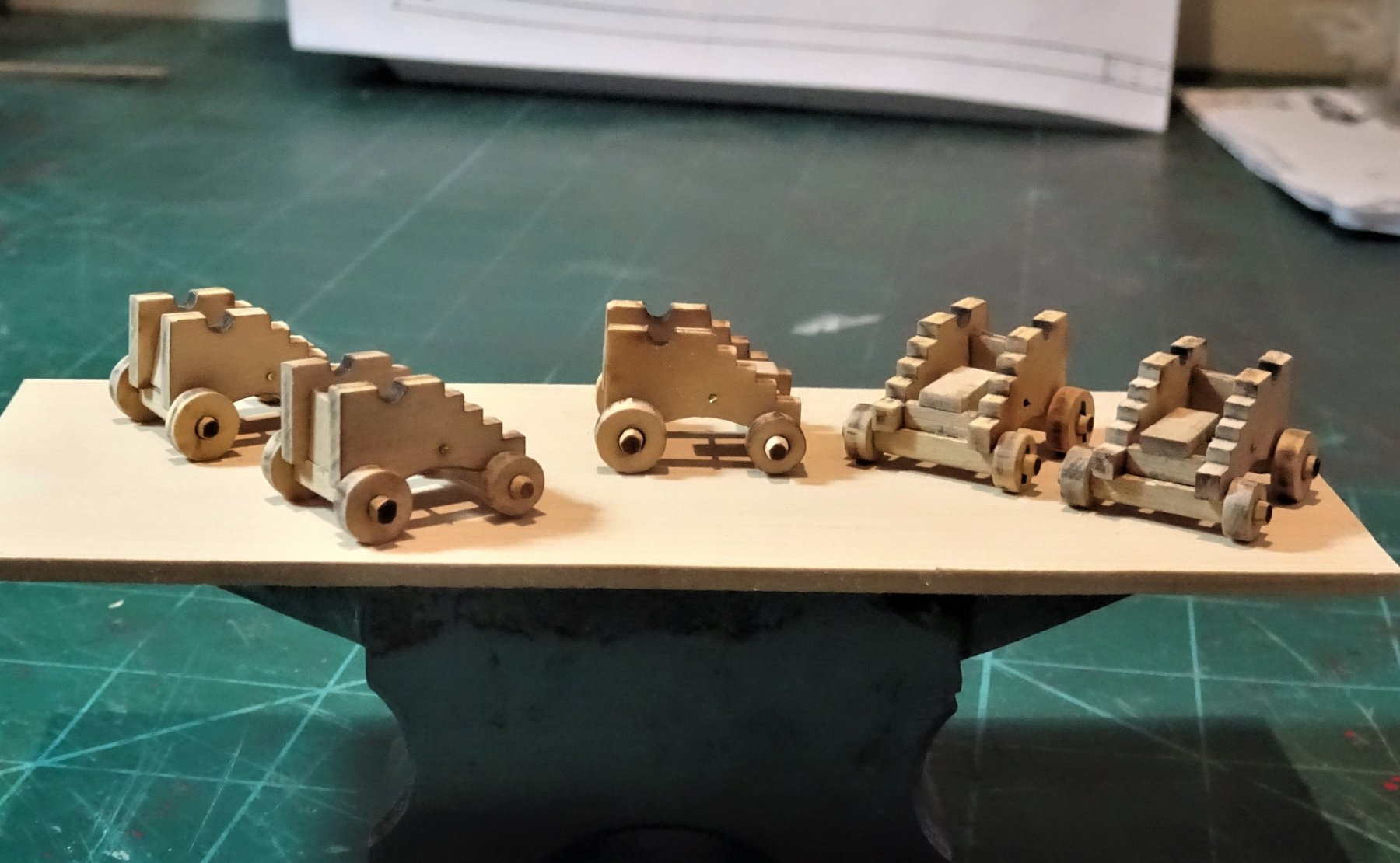
Post 59 Assembling the gun Carriages I did assemble one gun earlier in the build for the purposes of gun port fit, but this is a multi stage and repetitive assembly process and I decided I should make a start. To recap... 4325 I had already made a simple jig to hold the axles. The axles are rounded at each end to take the Trucks before fitting in the jig for the attachment of the transom on the front axle, and the Bolster on the rear axle. 4322 One point to note is that the Transom above the front axle is not vertical but should lean back slightly. I used some 0.7mmø wire, chemically blackened to represent the iron connecting bar which ties the side brackets and supports the carriage bed. 4331 This is not a quick process, and becomes rather tiresome, but at least not as tiresome as having to make the carriages from scratch. Removing the lazer burn and rounding the axles is heavy on time and patience, and using a jig for assembly is absolutely necessary. I decided to construct the carriages before painting and decided on a Red Ochre scheme. Initially I thought about leaving the trucks natural, but to my eye, and as Chuck also found, they didn't look good, so they also had the red ochre treatment. Once the basic assembly is completed there is still a lot to do; ring bolts and eyebolts, capsquares, truck keys, and bolts. For the carriage ring bolts I used Amati 2mm brass rings which are pretty much true to scale. For the eye bolts or hoops I also used fine Amati eyebolts, set slightly into the carriages. For the bolts I also used Amati 10mm fine brass pins. These have slightly domed heads of less than 1mm ø and stems of 0.5mm. Once I had assembled five carriages I went on to fully complete one example. 5341 Still some cleaning up to do, the trucks are not glued to the axles. Drilling the 16 holes to take the various fittings needs to be done carefully, and it is a fiddly little job cutting the bolts and eyebolts to size. 5335 The eyebolts for the side tackles are set well into the side of the carriage. 5336 I added Truck keys to retain the trucks on their axles. They were made using 0.5mmø pin stems flattened at one end These were then chemically blackened after trimming. 0.60mmø holes were drilled thro' the axles to take the key. 5317 5338 Only another eleven carriages to go, and then there's the Carronades, I think I could be some time. B.E. 10/01/2019


- 574 replies
-
- 21
-
-
- cheerful
- Syren Ship Model Company
- (and 1 more)
-
Cheers guys for looking in and for your comments. @ Martin - Yes I did use the scroll saw to get the basic shape, but then it was down to files and scalpel to finish off. @ Dave - Thanks Dave I have had a couple of near misses with the crutches, need to keep the stern away from the wall. I'm still undecided about the swivels but I've kicked the decision into the long grass for the present. @ Jason - I'd have had trouble working out the deck plank curves too if not for Chuck's lead and guidance, but once you've got it it's basically like planking a hull around the bows. B.E.
- 574 replies
-
- 1
-
-
- cheerful
- Syren Ship Model Company
- (and 1 more)
-
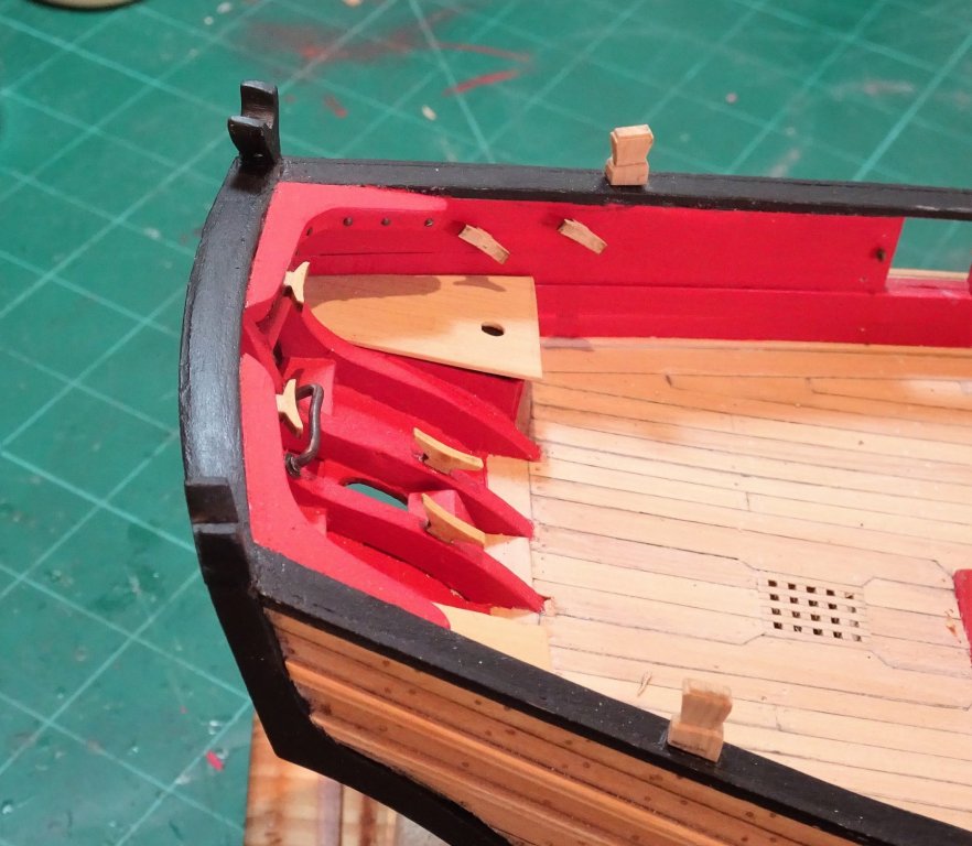
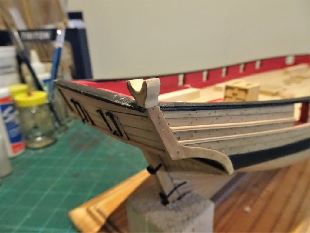
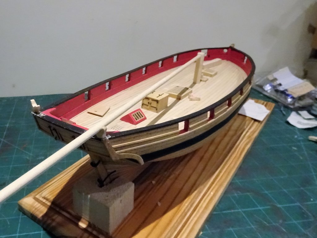
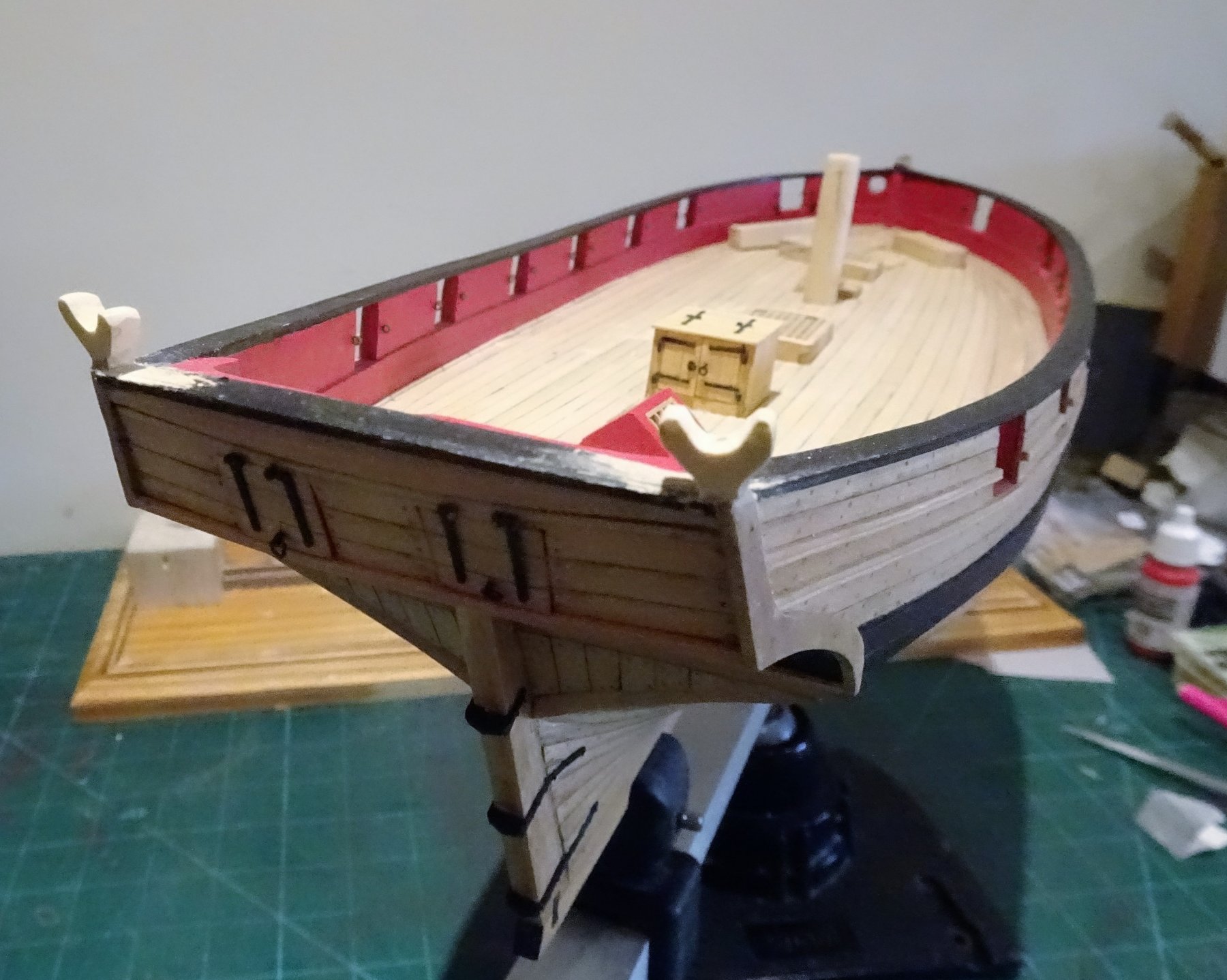
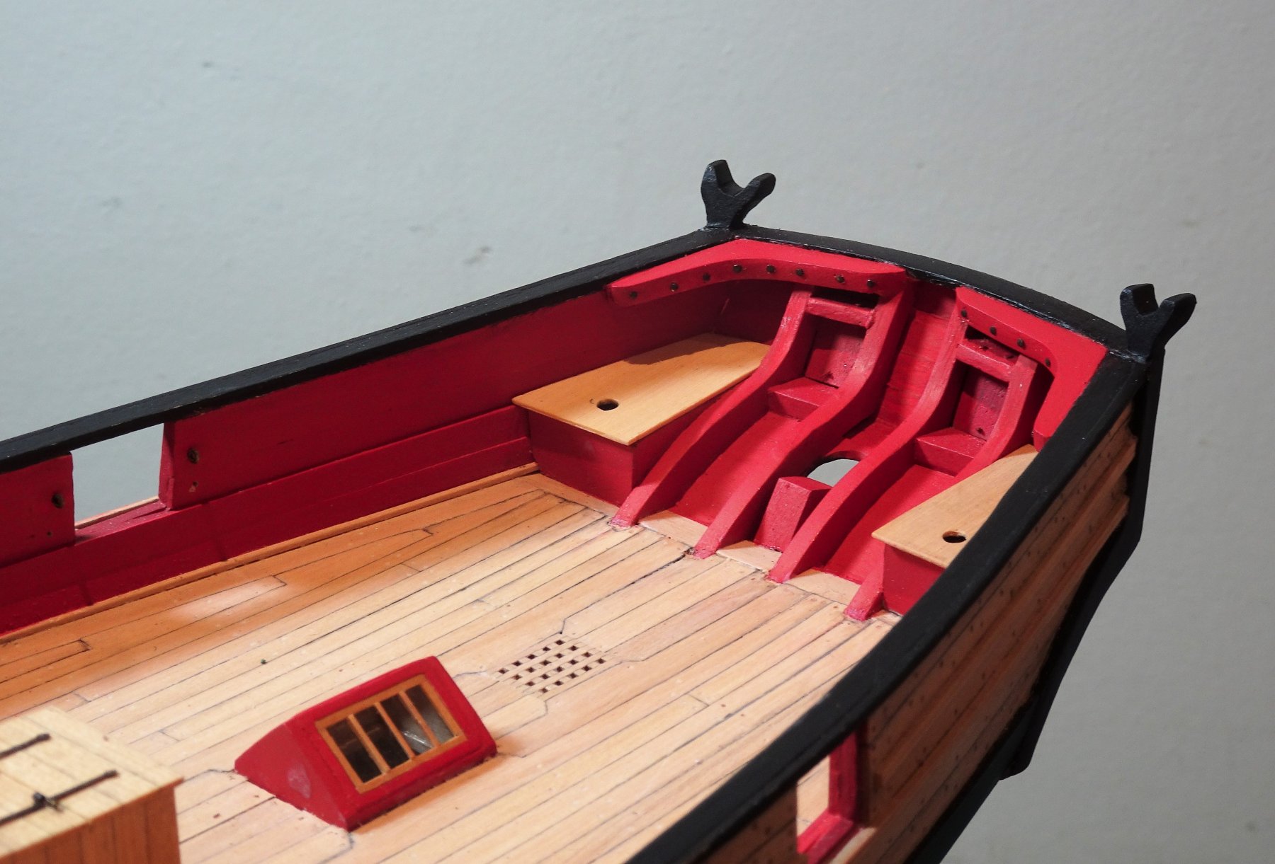
Post 58 Boom Crutches. Interesting little project to make these and I am grateful to Chuck's guide on the subject. I originally started with a 12mm wide strip cut from some 1/4" Boxwood sheet. but I found that I ran out of angle to give me sufficient height. For my subsequent attempts I used 15 x 20mm section- and there were several futile attempts to get something that looked even barely acceptable. The block is secured on the transom with a strip of double sided tape to mark the fashion piece angles, and the process of filing and sanding begins. 5101 These crutches are quite small and awkward little things to hold and shape so I reach the point where I think it better to glue them to the transom and finish off shaping with both hands available. 5110 Using a jury rig to assist with the rotation of the crutch. Chuck makes the point that it should turn somewhat inwards to receive the boom. 5144 Even so a couple were glued on only to be ripped off when I found the opposing one looked better, and so it went on. A couple of the sad little rejects lie on the deck. 5139 Eventually I convinced myself that the resulting pair didn't look too bad a match and I resolved to permanently fix them. 5153 They seem very vulnerable sitting up there atop the rail so I added a bolt thro' the crutch and into the transom. 5154 In this shot the completed Transom knees can also be seen. I pondered a little over the colour scheme for the knees but eventually decided on red as they were below the level of the rail, and to my eye looked less heavy than black. The retaining bolt heads can also be seen; I did wonder whether to include these, but I felt they should be there, and they do seem be shown on Chuck's plan. 5170 5172 The Fashion pieces were also painted black at this point. 5166 The internal lead discharge piping for the Seats of ease was added. Totally unnecessary of course and will probably never see the light of day again, but I know they are there. 5161 The circular outlet flanges were represented by flattened slices of Aluminium tubing, chemically blackened. 5168 5152 So where to next, I think I will tackle the Timberheads, and make a few cleats but I also need to consider whether to fit Swivel posts. I have been having second thoughts about this. Neither of the historical models of either Cheerful or Surly are fitted with swivels and all the cutter examples I have seen with swivels date from the mid to late 18th Century and of course Cheerful is an early 19th century cutter. However, Lavery (Arming and Fitting) does indicate their use on naval ships until 1815, and I can imagine that a couple of swivels in the stern and bow areas would prove useful. One of the fascinating aspects of our subjects is that there are always more questions than answers. B.E. 04/01/2019


- 574 replies
-
- 18
-
-
- cheerful
- Syren Ship Model Company
- (and 1 more)
-
Well done Martin, I like them, and would be really pleased to have produced such detail on tiny figures. B.E.
- 467 replies
-
- 2
-
-
- fly
- victory models
- (and 1 more)
-
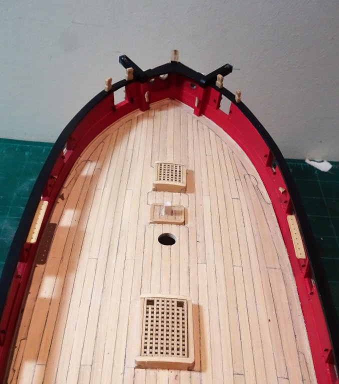
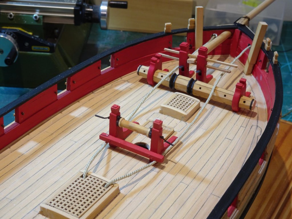
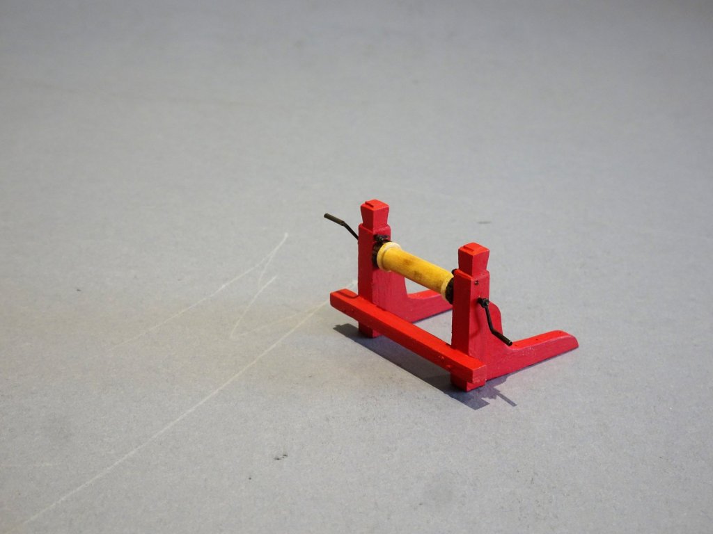
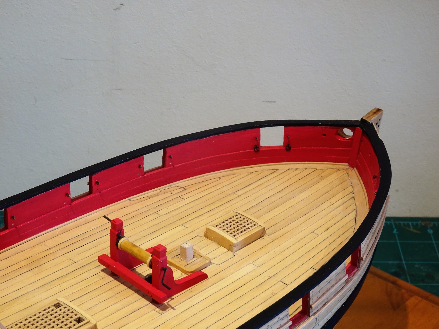
Back at the workbench but I have continued to dabble over the Christmas period, but a heavy cold with running nose is not really conducive to bench work. Thank you for your Christmas greetings, and good wishes for a successful modelling year are returned. I have a cunning plan Martin that by including a photo of William I will detract attention from the more obvious examples of my skill deficiencies. That little plane by the way looks sweet but keeping the blade sharp is a real pain. I tend to use my full size but compact Bullnose and shoulder planes mostly, they are a delight. Post 57 Scratching the Winch Having got over the shock of not having a Chuck mini kit to produce the Winch I got down to scratching this last of the main deck fittings. Fortunately I do have some old Boxwood square stock a tad in excess of 4.5mm which will do nicely for the Winch Bitt pins (uprights). Hand sculpting using a scalpel produces the traditional timber head style. 4975 I opted to run a spindle thro' the winch drum rather than just glue it between the uprights. Chuck's drawings show the cross beam notched to fit over the Bitt pins. My understanding is that in practice the uprights were scored slightly to take the cross beam, which on this build would work out at just under 1mm. There are excellent drawings at 1:48 scale and larger, of winch details in the book The Naval Cutter Alert by Peter Goodwin. 4978 I used the mill to cut the slots and drill the necessary holes to take the barrel. The Winch drum, end caps, and pawl ratchets were cut from rounded boxwood section. Having cut the uprights to length holes were drilled in the base to take retaining pegs when the assembly is finally fitted to the deck. The standards were traced from the plans onto a card template and cut out of 3mm boxwood sheet. I found cutting the ratchet teeth along the edges of the pawl drum one of the most tricky aspects of the process. These little discs are only 6mm in diameter. I fashioned the crank handles from some left over brass fittings from my Pegasus build ( stanchions)and some micro tubing. I also added the pawls also made from some left over brass etch, but these are very tiny. 5052(2) 5054(2) 5056 5030 Stern Transom Knees. Cut from 1/8th" Boxwood sheet, fitting these caused me a fair bit of head scratching. The thickness means that the transom frames get in the way which means they either have to be cut back to allow the knees to sit flush against/beneath the rail, or the knees have to be notched on the underside to fit over the frames. 5078 I eventually got there by a combination of fining down the stern frames a little, and notching the back side of the knees. 5084 I will return to complete the knees later in conjunction with the Boom Crutches. B.E 01/01/2019
.thumb.JPG.e5f00c1af0f6876e00d95d3a0e7e9217.JPG)

.thumb.JPG.6a46566c8b664f47ba4360f73908a9d3.JPG)
.thumb.JPG.a9f434c0183b4988dc52aab0839fcdb0.JPG)


- 574 replies
-
- 17
-
-
- cheerful
- Syren Ship Model Company
- (and 1 more)
-
I never use black scale line either, far too harsh. I colour mine using a dark Jacobean oak wood dye, it produces a nice scale black/brown colour which fades somewhat over time. I prefer it to even the available brown shades. B.E.
-
A fascinating insight to life below decks on an 18th c 1st rate. Nice work Michael, fine detailing. B.E.
-
Looks very nice Chuck. I have used Morope a fair amount and as you say the definition with Polyester superb. The only downside for me is that it is all but impossible to get a natural slack in the line which I like to see in certain lines such as braces, and some stays. On the upside very little pressure is required to get a taut line, and I love the smaller diameter Morope lines for seizings. B.E.


.JPG.5a85d37e7e66c52c3ffb12b1ec2a1bc4.JPG)


.JPG.2f40176b03cd4c9100d2ac0aaa8834cf.JPG)


.JPG.a10a1adbe539455f7506c13fabf20303.JPG)

.JPG.20cd5185c6cfba5c77c156c31a9684c8.JPG)
.JPG.bfd930ea3d3c549f767e13a7244d4d71.JPG)