HOLIDAY DONATION DRIVE - SUPPORT MSW - DO YOUR PART TO KEEP THIS GREAT FORUM GOING! (89 donations so far out of 49,000 members - C'mon guys!)
×


Louie da fly
-
Posts
7,989 -
Joined
-
Last visited
Content Type
Profiles
Forums
Gallery
Events
Everything posted by Louie da fly
-
 Beautiful job, mate. She looks very good. It wouldn't be a proper ship build if you didn't learn something to do differently next time Regarding small tweezers, have a look at the ones used for personal grooming. I bought a set of them, all with different 'business ends' quite cheaply at s department store. Steven
 -
It just occurred to me that maybe we've misinterpreted the meaning of the title of this thread. Sorry (couldn't help myself) Steven
- 27 replies
-
- 10
-

-

-
Yes. But as well as external wales for strengthening, most of the ships I encounter (mediaeval and renaissance) also have stringers inside the hull, doing a similar job. Except perhaps for looking nice . . . Steven
-
Beautiful work (as usual), Greg. I love your 20th century warships; even though it's not something I'd want to do I can recognise quality work when I see it and be impressed by it. Steven
-
https://news.err.ee/1609172593/europe-s-oldest-compass-found-in-lootsi-wreck-even-older-cog-still-underground More information in links at the bottom of the article.
- 1 reply
-
- 10
-
-
Allanyed, I'm attaching (my own) translation of the article that appeared in Archaeonautica, but looking more carefully at the cross sections in Part 6 I may have been misled by the midships cross-section to think the wale lined up with the main deck throughout the length of the ship. Further inspection reveals that the wale is by no means present in all the sections level with the main - by which I mean the middle deck - between the orlop and the upper deck as shown in Fig. 50 (Cross-section at floor timber W70). To help with interpretation of the drawings, note that the partial sections (all of the ship that survived, unfortunately) are of the vessel as she was found - lying on her port side, so the keel is on the right of each section. Thank you for bringing this to my attention - I'm planning to tackle Lomellina as my next build, so I don't want to get it wrong. Steven Archaeonautica Lomellina article - English.pdf
-
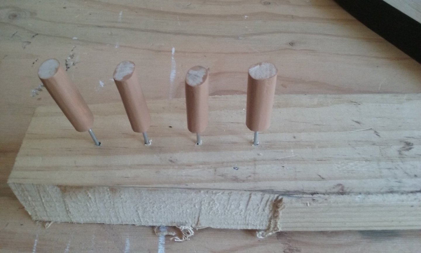
These will support the ship, but won't fix it firmly to the base - it's only held by gravity so it it could still tip over. You'll need to decide whether that's enough for you or whether you want to ensure that it's impossible for the ship to tip over and come off the base if jolted. Steven
-
Yes, I could have explained it in my previous post, but it was more fun to keep them in suspenders for awhile . . . Steven
- 30 replies
-
- 2
-
-
- roman
- merchantman
- (and 2 more)
-
Very impressive! It wasn't till I saw that photo that the 1:25 scale sank in . . . Where do you find the room for all these models? Steven
- 30 replies
-
- 2
-
-
- roman
- merchantman
- (and 2 more)
-
I don't know about other ships, but I do know that the main wale on the Lomellina (sank 1516, probably built 1503) was exactly in line with the main deck. But my understanding is that wales were effectively just thicker, heavier strakes, so other strakes would be placed in line with them. Steven
-
They'd better be! Much more work in this model than $200 worth! Oh, no. Woodrat beats me hands down. From 1600 B.C.E. Mycenaean galley to 1440 C.E. carrack/nao - that's over 3000 years - still more if we include his 18th century Gros Ventre. But I think I can claim the widest chronological gap for two builds going on simultaneously. Steven
-
Interesting. In New Zealand, the Maori dug-out war canoe is called a Waka, and the building process (including the ceremonial and religious aspect) was very similar to that of the Hawaiians - see John Allen's fascinating build at
- 174 replies
-
- 5
-
-
- Waa Kaulua
- bottle
- (and 1 more)
-
You've done a beautiful job with this model. You can be justly proud of your results. Steven
- 13 replies
-
- 2
-

-
-
- Golden Hind
- Airfix
- (and 1 more)
-
Thanks everybody for the likes, and Javelin for the comment. Brand-new No. 11 blade in a craft knife. Steven
-
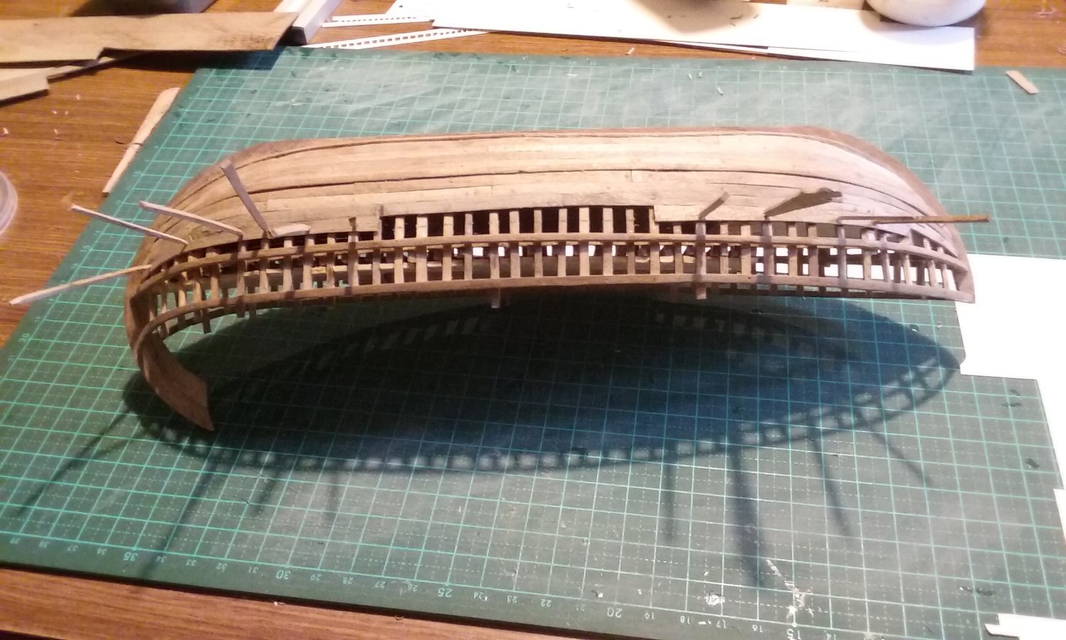
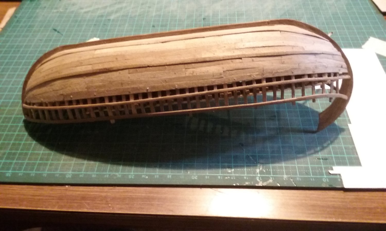
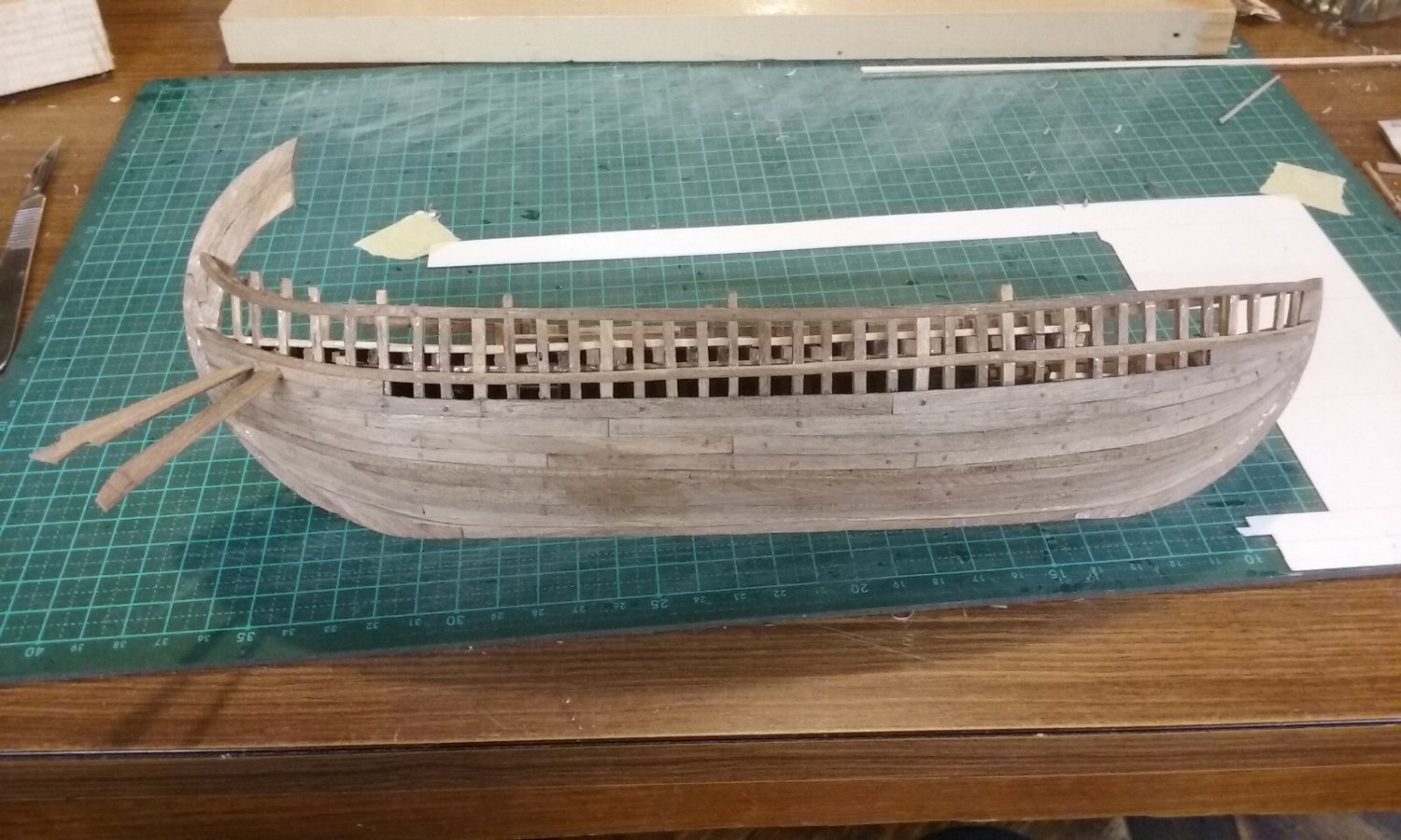
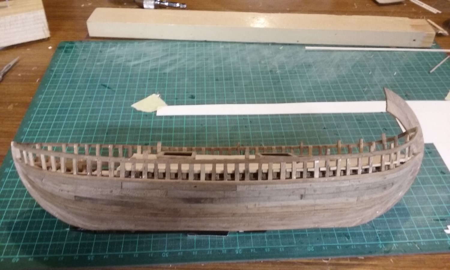
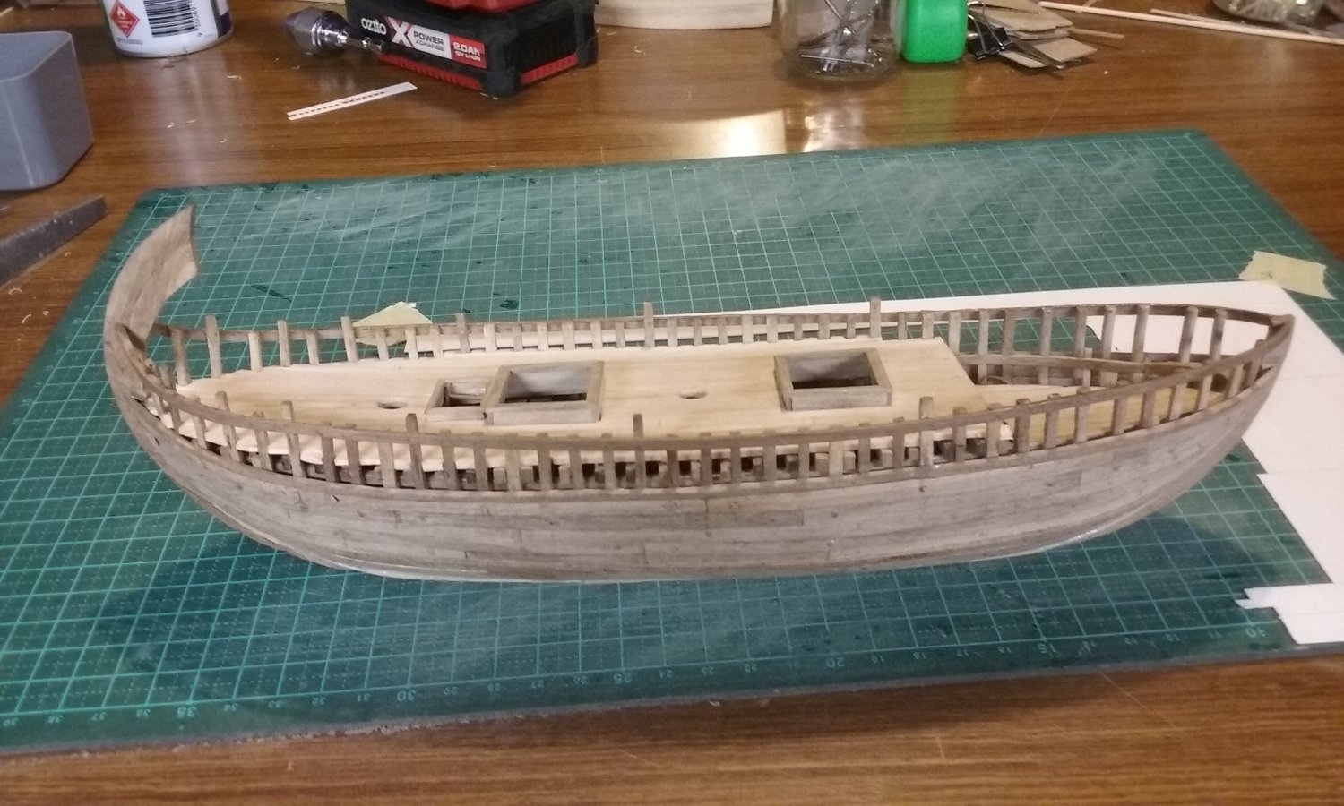
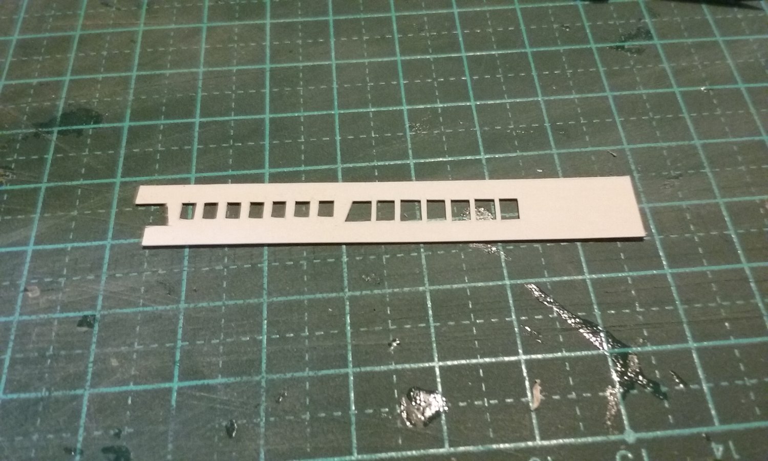
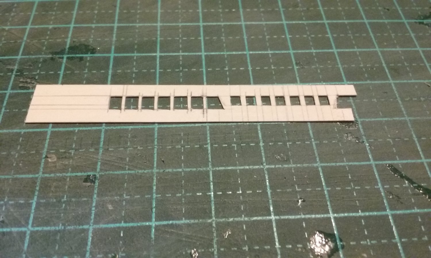
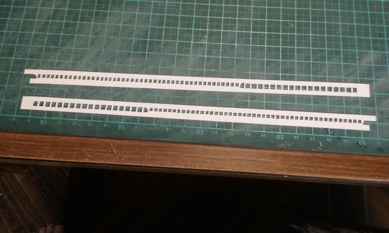
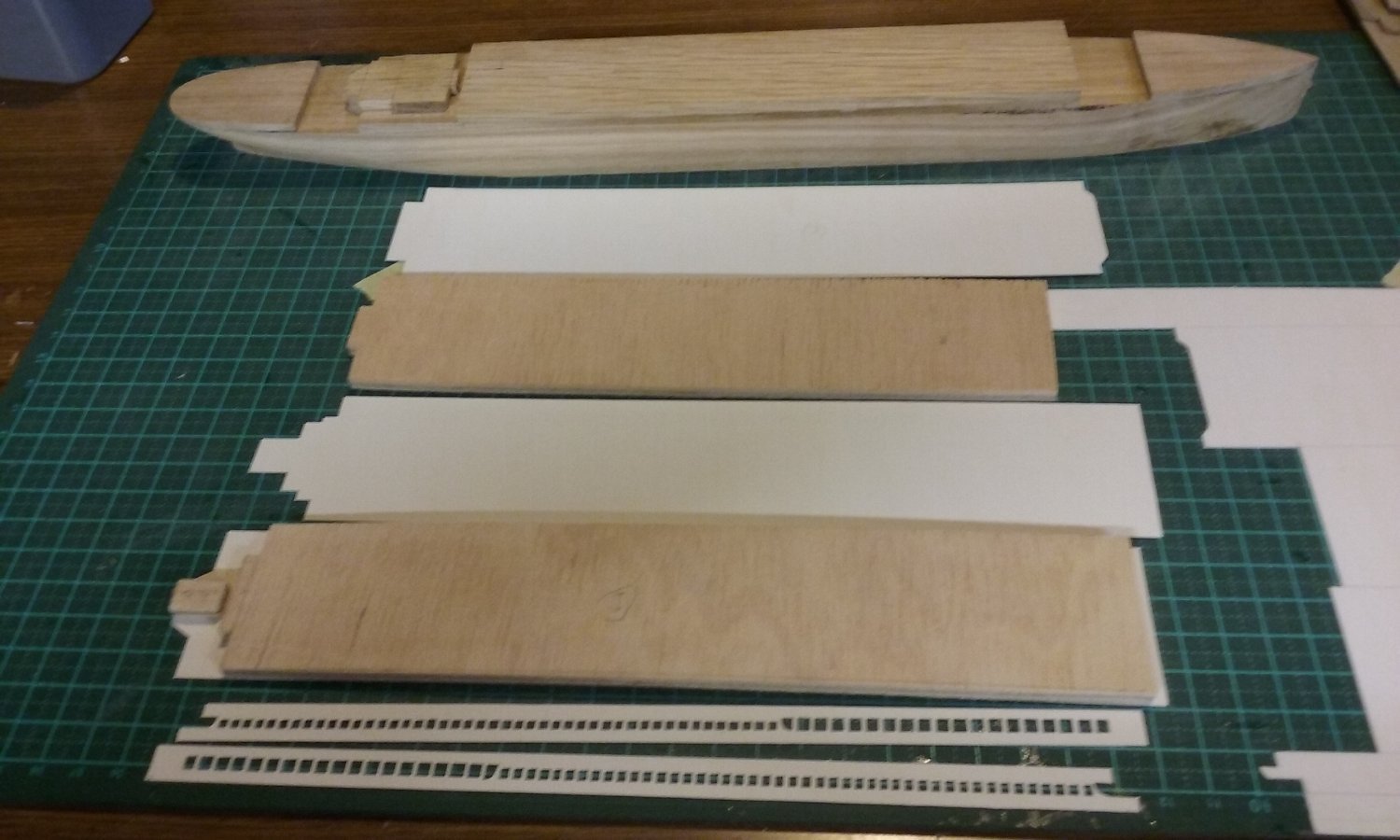
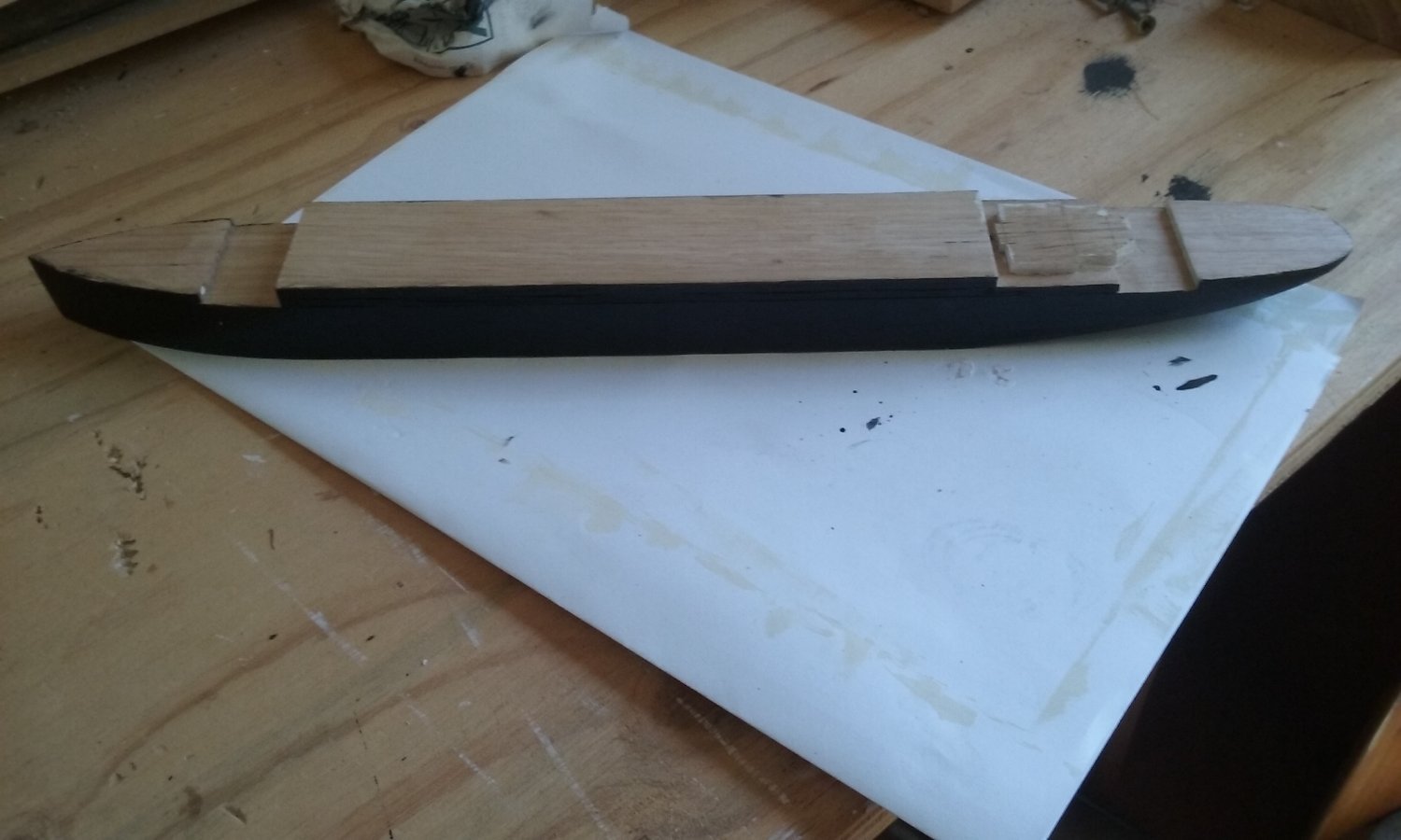
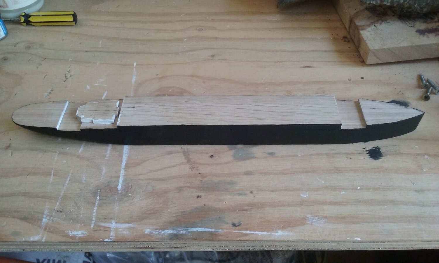
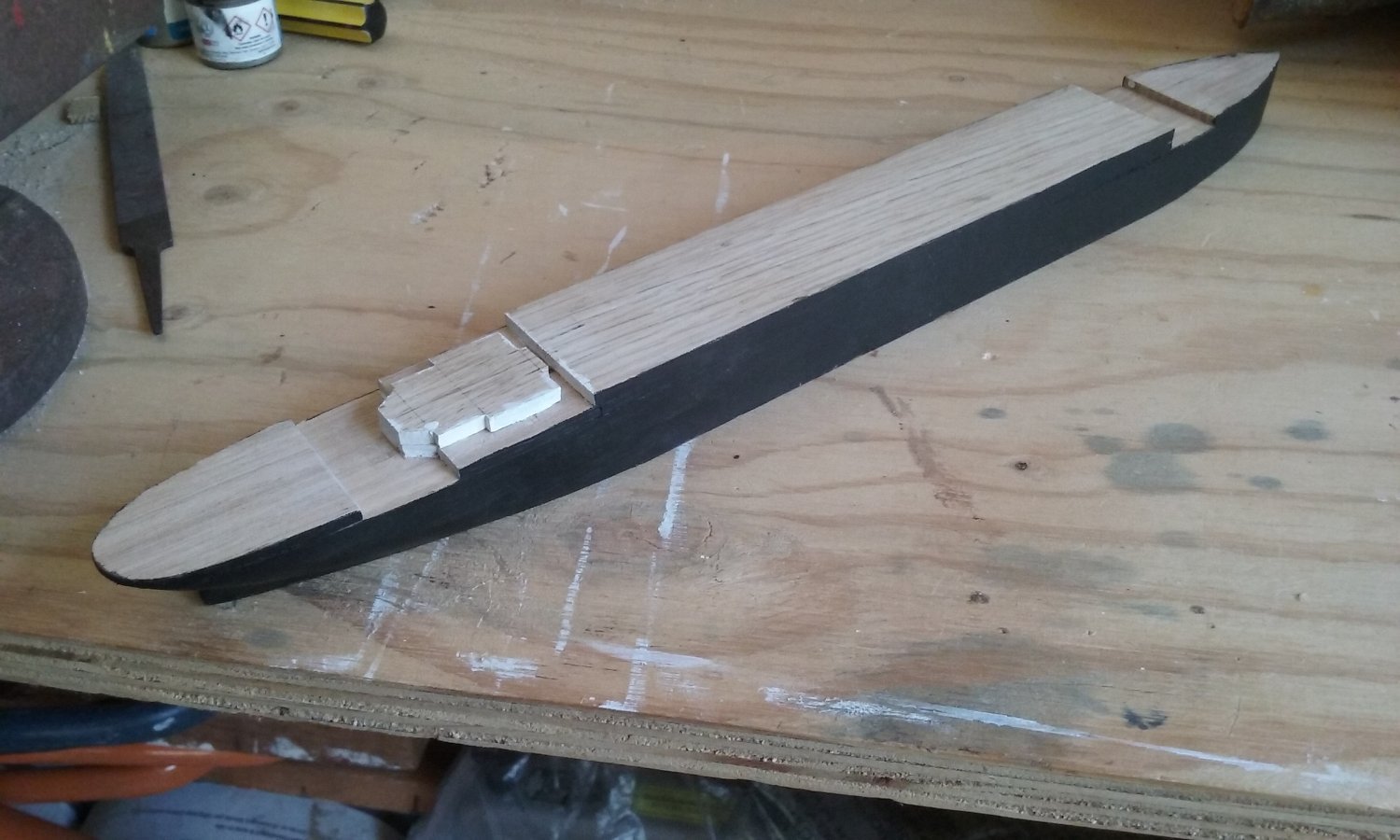
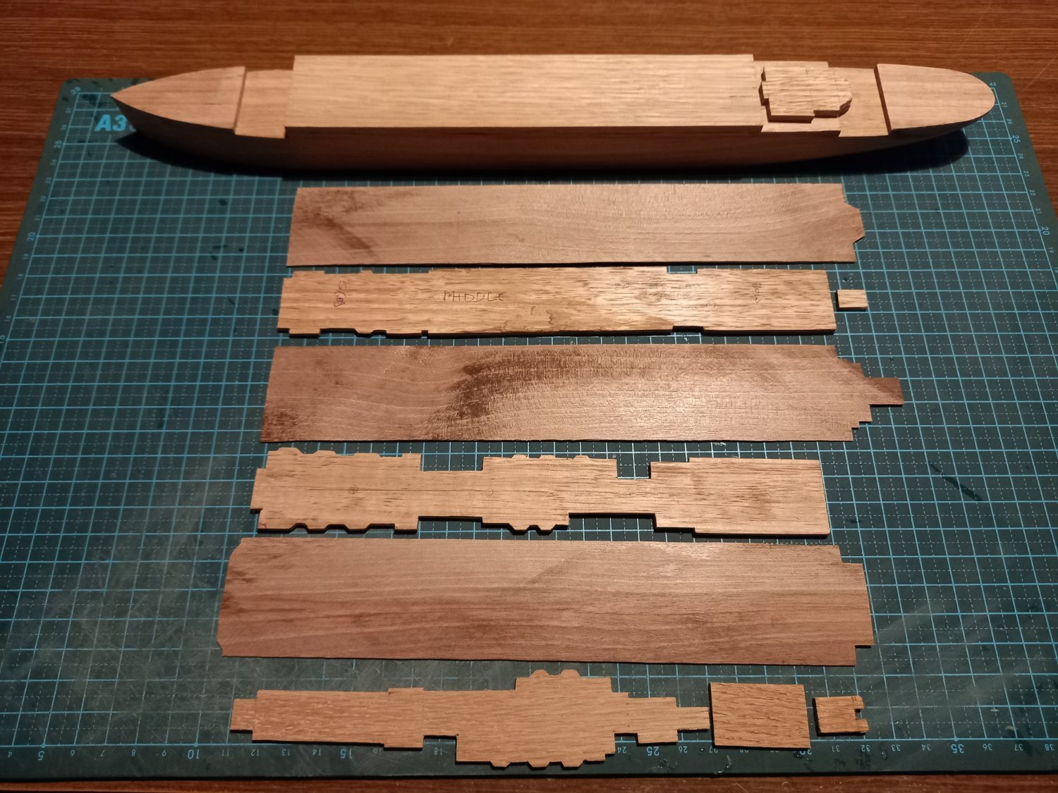
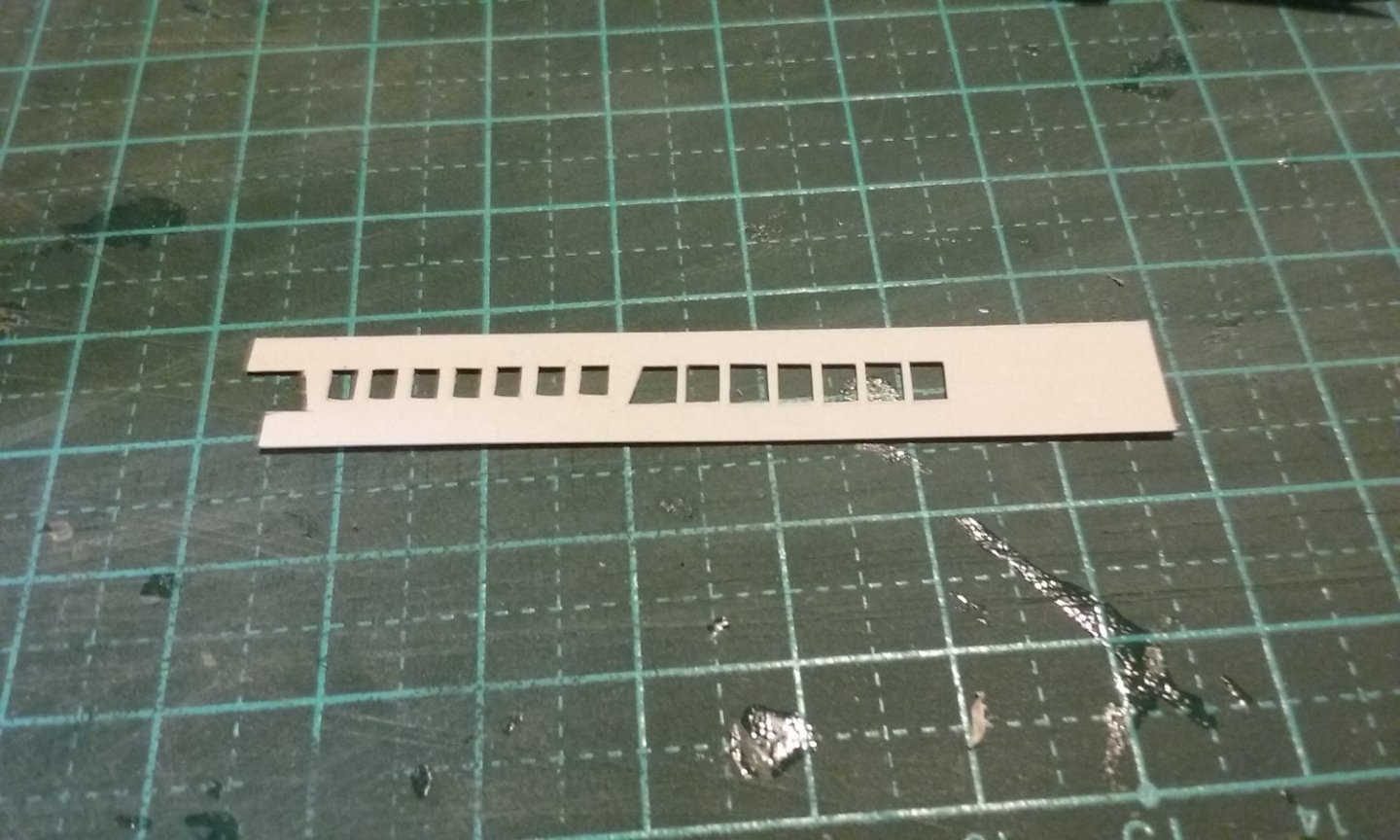
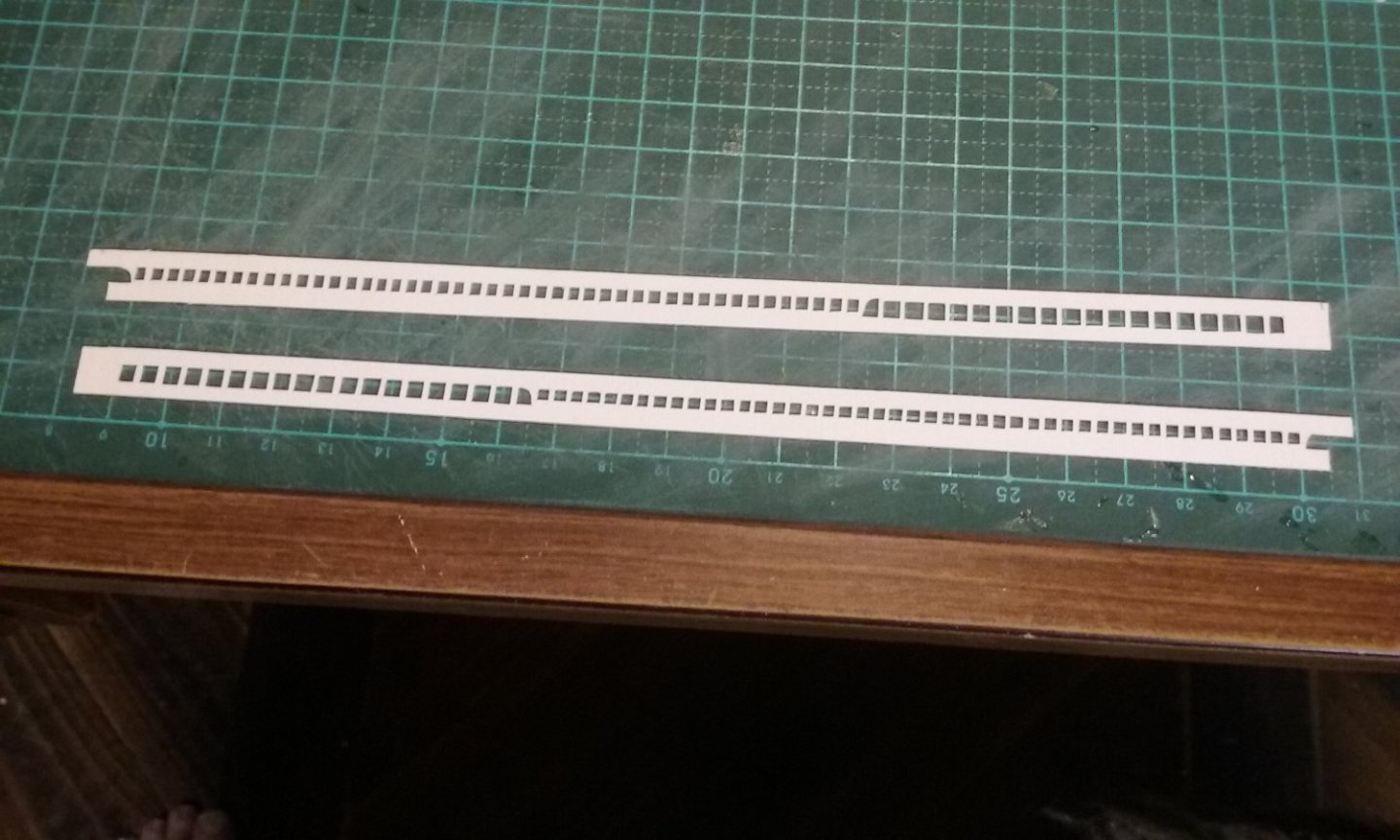
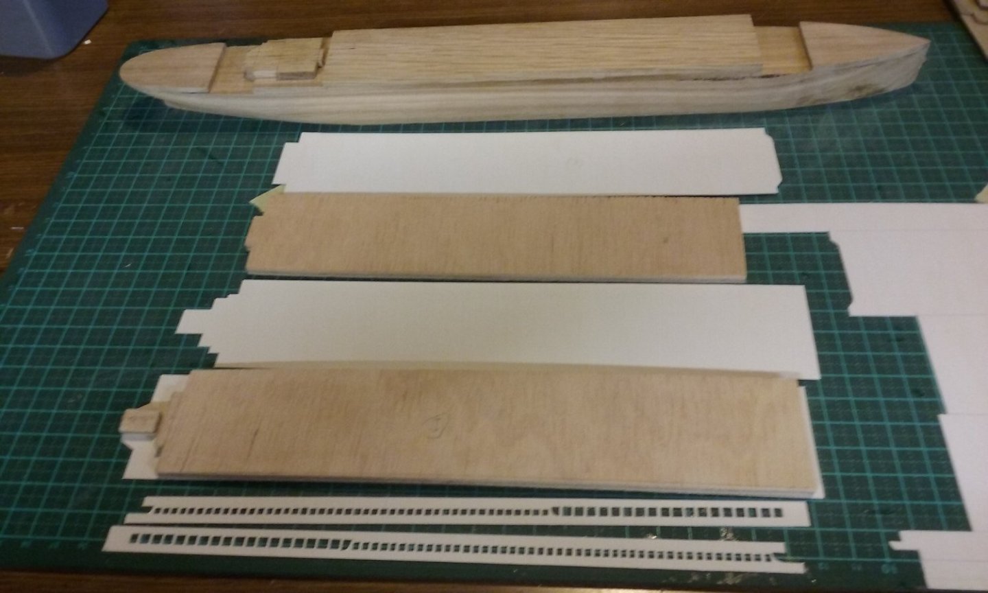
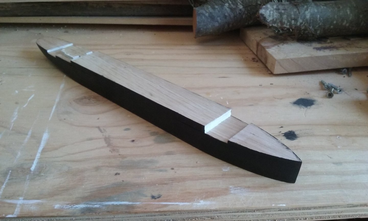
Change of plan. The decks are to be made of card, and apart from areas where they are open underneath, each will be supported by a layer of sheet wood, as thick as the distance between the decks. And the windows/portholes/whatever between decks will be cut into card and glued onto the sides of these layers of wood. The edges of the layers painted black, to suggest empty space behind the openings. Though I'm thankful to Grandpa Phil for suggesting clear primer, I decided to go with white enamel instead, so all the "white" bits will match in colour. I did a test piece first: The enamel (Revell tiny tin) turned out to do the same job of stiffening as the primer probably does - nice clean cuts. Reverse side with the openings marked out in pencil: And the "face" side: Here are the first two pieces: And all the components: Hull painted black, and the edges of the "tweendecks" structures painted white where they can be seen (except at the break of the forecastle - I'm going to try gluing card onto that face and see how that turns out. Note that the forecastle and poop actually weren't that high - the extra height was made up by bulwarks, but I've oversimplified the build (also I hadn't realised about the bulwarks till too late ). A little tidying up needing to be done, but overall I'm pretty happy with how it's going now. Oh, and the funnels (started with dowel and shaved it down to oval shape). Paint drying. Once that's complete I'll paint the characteristic black "hoops" at the top. Steven


- 27 replies
-
- 16
-
-
Nice to see you back again, hlipplaa. Steven
-
Very good idea with the brass pin. I've certainly come across the same problem with things breaking off, and I ended up pinning items like this in place. Steven
-
Sounds good. This kind of information is usually confined to archaeologists - to see it in a model would be of great value. Steven
- 30 replies
-
- 3
-
-
- roman
- merchantman
- (and 2 more)
-
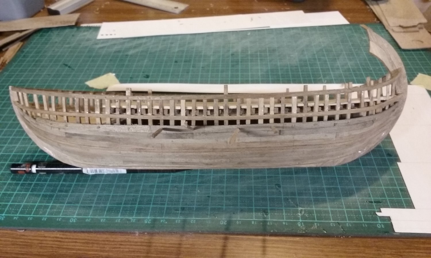
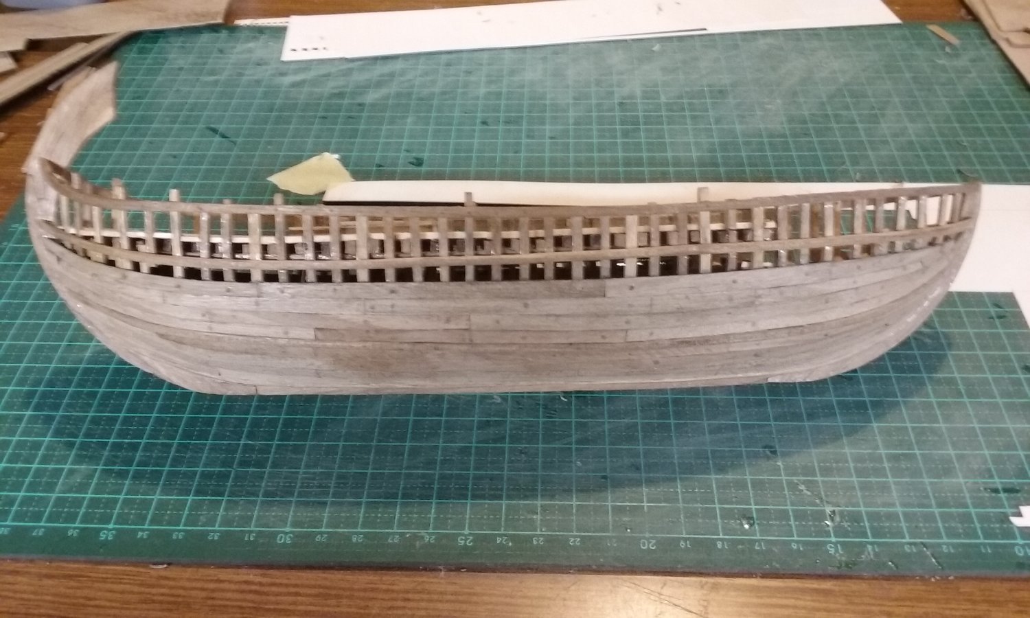
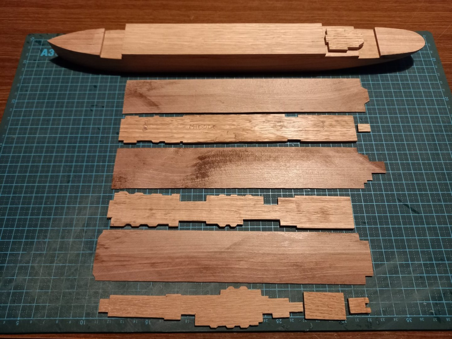
Yeah, I thought of that, but there would probably be gluing problems (I haven't used plastic sheet before) so I think card would probably be more suitable. Here are the hull and deck and intermediate (tweendecks) structures so far. The decks themselves I made from thin sheets of walnut but unfortunately they have "cupped" and I had to resign myself to heat straightening them. Then I remembered I'd been given some very thin sheets of (maple?) from cigar boxes. Nice and flat, so I'll be using them instead. Steven
-
Nice idea, mate. This would work with plastic ones, too - so no probs with clamps getting glued to the ship (well, not if you use PVA glue, anyway).
- 24 replies
-
- 2
-
-
- Ships boat
- Ships of Pavel Nikitin
- (and 1 more)