DONATION DRIVE - SUPPORT MSW - DO YOUR PART TO KEEP THIS GREAT FORUM GOING!
×

David Lester
-
Posts
679 -
Joined
Content Type
Profiles
Forums
Gallery
Events
Everything posted by David Lester
-
 Hi James, You're doing a great job! I too am a Bob Hunt alumnus and to be honest, I could never have grasped the process of building these models without him. I started with his Armed Virginia Sloop practicum and moved directly into the USS Consitution. After that I found I didn't need them any longer, as I was able to work on my own. Most of my models have been MS and I believe that you can basically throw the instruction book away. (Chuck Passaro's excepted.) Everything you need is on the plans, but they are absolutely dense with information and it takes a bit of experience to learn how to decipher them. You're off to a great start and it looks to me like you've have a fine Bluenose when you're done. David
 -
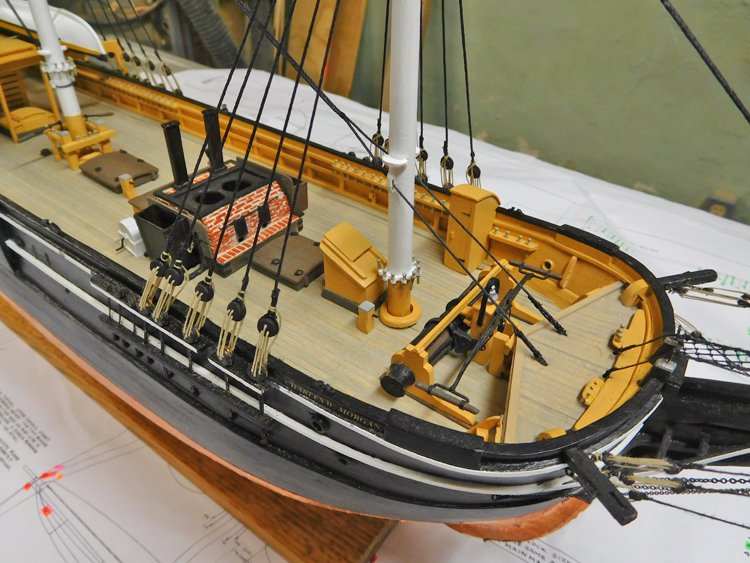
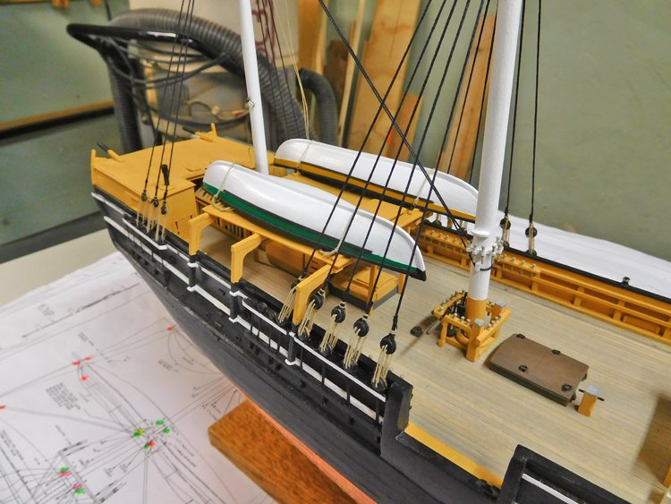
Good Morning, With the lower shrouds and lower stays in place, it seemed like a good idea to stop work on the standing rigging and add the five boat handing stations at this point. I also added the ratboards as well. The ratboards were fun to do and actually quite a bit easier than regular ratlines. I always have a problem with the outermost two shrouds pulling in as add the ratlines, but that was not a problem in this case. I've also finished the five boat handing stations. While they were not difficult, it was a much larger job than I anticipated as there are many components to each one. The hull of this ship has an incredible number of things on it and someone had advised me to take a great deal of care at the outset and when adding any element to the hull to be quite aware of how it would affect the placement of other components. It was a challenge making sure everything would fit in more or less the right place. I'm happy to report that everything fits properly and I didn't have to make any "do overs." Now on to the rigging in earnest. David
.JPG.03d64c228e20699108845f04617358bd.JPG)
.JPG.fd833c5f20749b7ae11687d3dea89338.JPG)
.JPG.1950259475d742d8119ea90182659ce8.JPG)
.JPG.294d81e9270cd46f3e436425bad3c517.JPG)
- 145 replies
-
- 14
-

-
- model shipways
- charles w. morgan
- (and 1 more)
-
Hi Felix, Have you tried Cornwall Model Boats? They have Artesania Latina rigging thread. They ship very quickly and inexpensively to Canada. I use them all the time. David https://www.cornwallmodelboats.co.uk/acatalog/artesania-rigging-thread.html
-
Hi Dave, I'm enjoying watching your progress and noticing your struggle with tapering the planks. The MS Constitution also has tapered planks. Each plank runs the full length of the deck and must be tapered so that all planks fit in at the aft end. I think you're on to the solution with the xacto chisel blade and sanding stick. I too tried the holding the ruler down on the plank and cutting along its edge without any success. (Virtually impossible to hold everything tightly enough.) I think you've found the solution with the xacto chisel blade and sanding stick. I did something similar. I didn't have a chisel blade, but I did use an xacto blade. I don't recall if I used a straight (#11) or curved (#10) blade. I needed to reduce the width of the planks from 3/32" to about 1/16", so I drew a line along the plank from point where I wanted to start the taper to the end. At the end where I was removing a full 1/32" I cut it with the knife and then sanded the full length of the taper smooth. (I use a piece of paint stirring stick, about 6" long with self adhesive sandpaper attached.) I didn't fuss too much about getting each one exactly identical, just more or less the same. I applied the planks working out from the centre line, first one side then the other and tried to keep the two sides more or less equal. However, the closer I got to the outside, the more attention I paid to the width of the planks, as I didn't want to end up with any that needed to be tapered to a point. Anyway, that method worked well for me and I'm sure you will find a great result too. David
-
Hi John, I'm no expert, but I now have a few builds under my belt and I attach the yards to the masts after all the masts are in place. I pin the yards to the masts with those tiny nails, but I locate and pre-drill the holes in the masts before mounting them. I drill the yard, cut the head off the nail and glue it into the yard, then attach it to the mast after the mast was in place. I don't glue the pin into the mast though as I want some movement in the yard fore and aft and up and down as I tightened the various lines and get the yard positioned . I used Bob Hunt's practicum on my Constitution too and I took his advice and attached as much rigging to the yards as possible prior to mounting them. It makes for quite a mess of lines hanging, but it's a lot easier seizing those lines and blocks on the bench than at the top of the mast. In my experience, while Bob's practicums are generally pretty good, he really drops the ball when it comes to the rigging stage. I suspect he hates that aspect of model building. I have all of his practicums, and in several of them it's quite clear that he hasn't even rigged the subject ship as he shows photos from other kits entirely and suggests that a certain aspect of the rigging will be similar to the photo. In the Constitution rigging section of the practicum there are many details left out. The foot ladders are one of them, he doesn't include the railings on the aft side of the mast tops and he omits the jackstays. I know there are other omissions too, but those are the ones that come to mind at the moment. I'm not sure why they're not included other than I suspect he gets impatient as he nears the end of the build and wants to get it done as quickly as possible. That's just a guess though. I really like Model Shipways plans, but there is a heck of a lot of information on each page and I have to go over the plans again and again to make sure I haven't missed anything. After a few MS builds I've learned how to read their plans effectively, but I was quite inexperienced when I built my Constitution and I know I missed a few things. I did notice the ladders and the rails on the mast tops and included those, but to be honest, I never even noticed the jacksays on the plans until it was way too late, so there are no jackstays on my model. I hope you have a great time as you get back to your Constitution. David
-
Hello All and thank you MicroMarine for that photo of the Scientific CWM. I've seen pictures of the ship when it had that configuration. Am I right in my understanding that it was not uncommon practice to paint gunports on the hulls of ships to make them look more dangerous than they were? Nere's a brief update on my progress. I've been working on two things simultaneously. The first is the ratboards: Here are some more in place, the upper two waiting to be trimmed along with the thread ends - Here are some after trimming and threads ready to accept the next one. I'm using a set of nail clippers to trim the boards and for some strange reason it really does feel like I'm trimming its nails.🙂 At the same time, I've been working on the five whaleboat stations. In my past builds it's just been a matter of sticking on a pair of davits and maybe a cleat or two and that's it. No so in this case. It's hard to believe but there are 30 individual parts in each of the five stations. Here you can see the davits in place - Here are the strips mounted to the side of the hull that serve as sliders. The thinnest wood I have is 1/32" and it looked a bit too heavy and I wasn't able to get the slight bow in them that's clear in pictures of the actual ship. So I laminated two pieces of styrene strip and that seemed to do the job. It was difficult to get the strip to adhere adequately to the top support piece that runs over to the hull, so I glued a piece of black construction paper to the top of the support piece and folded it up and glued it against the inside of the slider and that seems to secure it quite well. The remaining parts for each station are the boat bearers and cranes which are shown below, but not installed yet. The cranes attach to the bearers with a pair of eyebolts and pins. The challenge will be to install each pair of assemblies so that the two cranes are at the same height, in order for the boats to sit level. I resorted to vinyl again for the two fairleads on the side of the bearer. I could not shape basswood without it crumbling. Instead I laminated two pieces of thin vinyl strip together and drilled a hole near the end of the strip. Then I cut off a small square containing the hole and glued it to the bearer. When the glue was well set, I filed the round shape into the vinyl square. It's a detail that probably doesn't need to be there as the plans say that it is unknown what the purpose of these fairleads was. But they're on the plans, so I added them nevertheless. So that's where I'm at as of today. It's time to get back down to my shop as it's Wednesday and will soon be time for the Moth Radio Hour on NPR and I really hate to miss it. Thanks for all the likes, comments etc. David
.JPG.cd1786b31c2d64f264e2dd6360500cff.JPG)
.JPG.2f33cf46783a0b30af99eeaca8f2b2ad.JPG)
.JPG.c3c088b5b1a58d082f3463f1687f324d.JPG)
.JPG.77987b99a965456def06137adec5ebf8.JPG)
.JPG.84c15388393b89fadc946f71c7ccf18c.JPG)
- 145 replies
-
- 9
-
-
- model shipways
- charles w. morgan
- (and 1 more)
-
A little update. I've been working on this 'n' that. I've finished the cutting in tackle. Those Bluejacket cast metal blocks have great detail. They're a breeze to work with at this size (5/16") but a more difficult in smaller sizes. The plans indicated that the two lines from the cutting in tackle tie off on the windlass head and the windlass barrel. So clearly this tackle was not in place at all times, only when it was in use. The plans don't indicate exactly how to terminate the lines after being wrapped around the windlass, so I ended one set with a coil on the deck and I imagined the other set being tied off on the wooden bar above the windlass. I don't mind making rope coils for the deck, but I really don't like making the ones that hang down usually from belaying pins. I find them very hard to do. I have to admit to a bit of a cheat on these. I like using Amati rigging line generally; it seems to be very good quality without being expensive. I know that there is superior hand made rope available, but I find this one to be an excellent trade-off between quality and price. The problem with it is, it's a bit stiff and I can never get it to loop nicely for my vertical coils. I shouldn't tell anyone this, but I switch to a different rope here. I use crochet cotton for the vertical coils. It's much easier to get it to behave being very soft. The ecru is a nearly identical colour match and I always use a fine weight even if it's lighter than the actual rigging line. Again it's much easier to handle and the eye simply cannot pick up the slight difference. Then I made a start at the ratboards. A feature that's a bit different for this ship and although it's early yet, it looks like they're going to be fun to do. Still have to trim them to length of course. I find if they're trimmed to length first, it's very hard to tie them on the outermost shrouds. In the background you can see some boat davits in place. More about them in the next post. Many thanks for looking in, comments and the "likes". David
- 145 replies
-
- 14
-
-
- model shipways
- charles w. morgan
- (and 1 more)
-
Thanks for comments and likes. Much appreciated. David
-
Thanks Dave, I really appreciate it. I was worried about how to handle that ochre colour. I knew it didn't match any of the standard model paint colours. I contemplated mixing some to approximate the real thing and was pretty sure I could do that, but I knew I would never be able to repeat it and if I ran out or didn't have enough for touchups I'd be in real trouble. So I broke a cardinal rule and went to Home Depot and bought some sample sized house paint. There was a bit of trial and error; I probably have enough jars of "close but no cigar" shades of ochre to paint a small room, but in the end I got a decent result. I know using this kind of paint is a bad practice and I don't make a habit of it, but if you do it, Home Depot is the way to go. All the other paint suppliers only offer samples in one finish, which is flat. HD offers several different finishes in their sample sized jars and you can get the one you need. (By the way the larger Home Depot paint chips are a great size and weight to use as palettes for acrylic paints!) Thanks again, David
- 145 replies
-
- 1
-
-
- model shipways
- charles w. morgan
- (and 1 more)
-
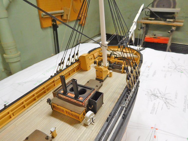
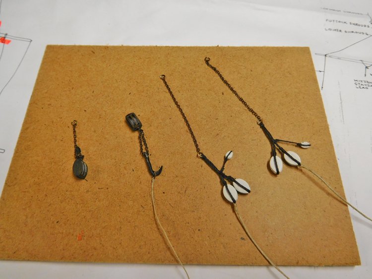
Good Morning, So this is pretty much a recap of where I am at the moment. Lower shrouds and stays are finished - The main stay passes through fairleads on the side of the fore mast and since the end point of the stay was previously established under the anchor deck, I knew I'd never position the fairleads correctly in order for the two sides of the stay to pass through without bending. So I didn't attach the fairleads to the mast first, but rather threaded them onto the stay, secured the stay in position and then attached them to the sides of the mast. You can just make out the port one threaded onto the unattached stay. Next up is the cutting in tackle, which in some ways is the centrepiece of this model. I'm following the advice of John (Texxn5) who suggests doing it at this point in the process. Here are some of the components prepared. I have never worked with 5/16" blocks before and boy are they ever easier to seize than 3/32"! I'm thinking maybe I'll replace all the 3/32" ones on this model with 5/16". How big a difference can it make? (Just kidding) Many thanks for checking in, comments and "likes" David

- 145 replies
-
- 9
-
-
- model shipways
- charles w. morgan
- (and 1 more)
-
Good Morning, I'm into the rigging for real now and have just finished the lower shrouds. I am always torn between using black or tan line for the lanyards. In theory, I guess, it should be tan, but it often looks very black on actual ships. I assume it's just dirty as opposed to being tarred. In any event I opted for tan on this model. I always think the easiest way to get the deadeyes (more or less) level is to just draw a line on a card, set it on the channel and use it as a guide. I always seem to have a bit of trouble tying off the lanyard without having to add a lot of glue, however I didn't have too much trouble this time. Thanks to John's (texxn5) photographs, it's quite clear how it's done on this ship. It's just a simple loop around the shroud and the end is left to hang just below the level of the rail. It wasn't too hard to achieve a decent result using this method and the loop holds really well when drawn tight, without using a bucket of glue. Just a light dab is all that's needed to secure it. Whenever I start the rigging portion of a build, I always have to find my "sea legs" again and it usually takes a bit of time before I get in the groove. As a result, this weekend I ripped out all the rigging I had done on the bowsprit and am now in the process to doing it over. 'til next time, David

- 145 replies
-
- 6
-
-
- model shipways
- charles w. morgan
- (and 1 more)
-
Hi John, I'm not sure how old your Constitution kit is, but if it's the same as mine, you'll find a conversion chart on sheet 7 of the plans. It shows the rigging line in decimal inches as well as mm. While there are many sizes of line indicated one the plans, and the sizes indicated don't always show up exactly on the conversion chart, you will be fine with three or four or maybe four or five different sizes, regardless of which kind of line you choose to buy. For example, .25 mm, .5 mm, .75mm and 1 mm (or thereabouts) plus garden variety sewing thread for seizing will pretty much work. If your plans are older and different from the ones I have, let me know and I'll send you a copy of the conversion chart. I have never liked the line included with MS kits, so I have always changed it. While I believe that the Syren line is probably the best available, it's also a bit expensive if you are as bad at using it sparingly as I am. I find a good option in terms of quality and value is Amati line which is available from Cornwall Model Boats. David
-
Hi Bob, With respect to the internally stropped blocks, I'm mainly going on the strength of this note which appears on the plans: "Note that most all of the blocks currently on Morgan are rope stropped. The only blocks observed to be internal iron stropped are upper & lower topsail halliard chain block and sheet blocks, and upper topsail downhaul blocks. The lower cutting tackle blocks are external iron strop blocks painted white, strops black. Lower cutting-in blocks are not painted (weathered wood.)" This note is in the instruction book: "Model Shipways’ Charles W. Morgan kit was developed in 1994-’97. Plans are based on drawings and other information provided by Mystic Seaport, and from photographs taken by the author in 1994. The Model Shipways plans and instructions were reviewed by Mystic Seaport for accuracy. In 1983, Mystic restored Morgan as a double topsail bark. The museum relied on photographs and other documentation to depict the whaler as she appeared between 1892 and 1908. Those wishing to build the model in another configuration should consult the bibliography and the numerous photographs showing changes made throughout Morgan’s career. © 1997 Model Shipways" The ship was restored again in 2008-2013. Thanks to John at www.charleswmorganmodel.com, we all have access to his many and excellent recent photographs. Internal stropped blocks are in evidence in the photographs and because of the note on the plans I think it's reasonably safe to assume that they are not just a recent addition/change. I have been comparing the photos to the plans and generally I have noticed very few discrepancies. However, It does appear to me from the photographs that there are more internally stropped blocks on the ship today than are indicated by the note in the plan. When I have come across a minor discrepancy, I have been trying to stay true to the plans rather than the photographs. It's not always easy (for me, at least) to tell in the photographs what blocks I'm looking at, but so far as I'm able to discern it, I'm going to limit the number of internally stropped blocks to those identified by the note in the plans. Not sure if this lengthy epistle helps or hinders! David
- 145 replies
-
- 2
-
-
- model shipways
- charles w. morgan
- (and 1 more)
-
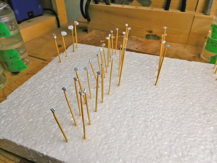
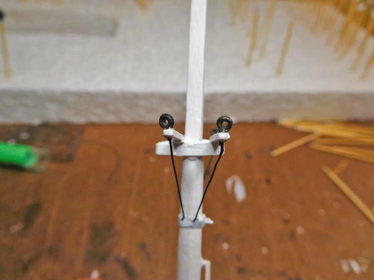
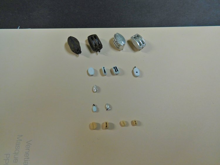
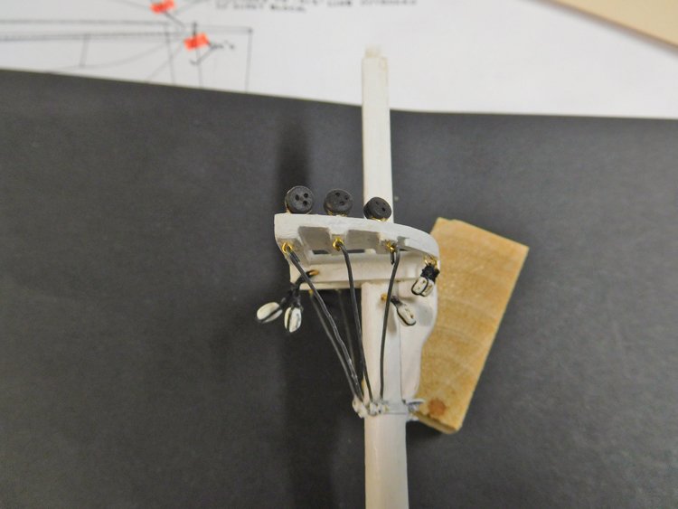
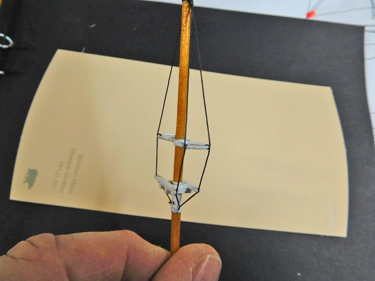
After some experimentation with upgraded blocks, I'm now ready to get going on rigging. I had decided to upgrade the blocks for this kit, which is something I hadn't done before. I was torn between Bluejacket and Syren. I could see advantages to both. It was really a toss-up, but I decided to order Bluejacket blocks. So what I found is this - at larger sizes they are absolutely superb and are beautifully detailed. At the smallest sizes however, they are difficult to work with. Because they're cast, they need to be cleaned up, which is ok at 3/16 and up but is quite difficult at 1/8" and 3/32". After many attempts, I discovered that I was never going to have success with the 3/32" ones in particular, so I decided to replace the 3/32" and 1/8" ones with Syren which are very beautifully made and will be easy enough to work with. So I'm going to have a combination of blocks on this model. There are also internally stropped blocks on this ship and I will use the Bluejacket ones for those. I can manage them even at the 3/32" size, as I don't have to wrap a line around the block. first row - Bluejacket 5/16". You can see the great detailing second row - Bluejacket 3/16", rope stropped and internally stopped third row - Bluejacket 1/8" fourth row - Bluejacket 3/32", internally stropped and rope stropped, the unpainted one requires some filing fifth row - Syren, 1/8" and 3/32" painting the blocks -several thin coats works best I'm rigging as much as possible prior to mounting the masts. For some reason there are no bullseyes included in the kit, yet the plans call for many of them. Picture above are Bluejacket 3/32" which are great. I will also be using a number of them at 1/16". They are very good. I think even the smallest wooden ones tend to look too large. Here is the combination of Syren and Bluejacket blocks (I still have to touch up the brass bits with black paint) Top mast - on the real ship, the rings are metal covered in canvass. To duplicate the look, I made loops out of brass wire and then covered them with white plumbers' tape. So that's my progress so far and my mini review of Syren and Bluejacket blocks. I don't think I'll ever do another model again without upgrading the blocks. They are so superior to the ones in the kit. I would recommend both, with the caveat that the Bluejacket ones will be difficult to work with in the smallest sizes. David

- 145 replies
-
- 7
-
-
- model shipways
- charles w. morgan
- (and 1 more)
-
Brief update - I've been working on the netting that goes over the bowsprit. I had imagined that I would just use the same stuff that I used for the hammock netting on my Constitution, but when I got it out, I realized it was much too fine. The bowsprit netting on the Morgan is very large. So, I made some up. It was really just like making shrouds and ratlines. I made a grid and then strung some vertical lines. (A you can see I made the grid wider than than I needed to have.) I used simple sewing thread, the kind I use for seizing. For the verticals, I doubled it. I used single thickness for the horizontal lines. The netting pattern is diamond shape, but I thought that would be too hard to do in a consistent way, so I tied on two diagonal lines to represent the outer edges of the netting. Then I was able to tie all the horizontal lines on at right angles to the vertical lines. I secured all the knots with diluted white glue and when it was dry, I cut it out and lashed it to the support lines on the bowsprit. There isn't too much more I can do by means of stalling before starting the rigging proper, which always seems like a big threshold to me. Anyway, I'm just about ready to bit the bullet and get serious about it. Thanks again for looking in, comments and likes. David
.JPG.95af32037100e7e5acd35a8ff4199c8f.JPG)
.JPG.b4ca2d82edcfcb74d0a56e177597a1a9.JPG)
.JPG.250adda415e100e3f5973678590cd131.JPG)
.JPG.5a34291a5770cd48b8e05ac72f6d5608.JPG)
- 145 replies
-
- 10
-
-
- model shipways
- charles w. morgan
- (and 1 more)
-
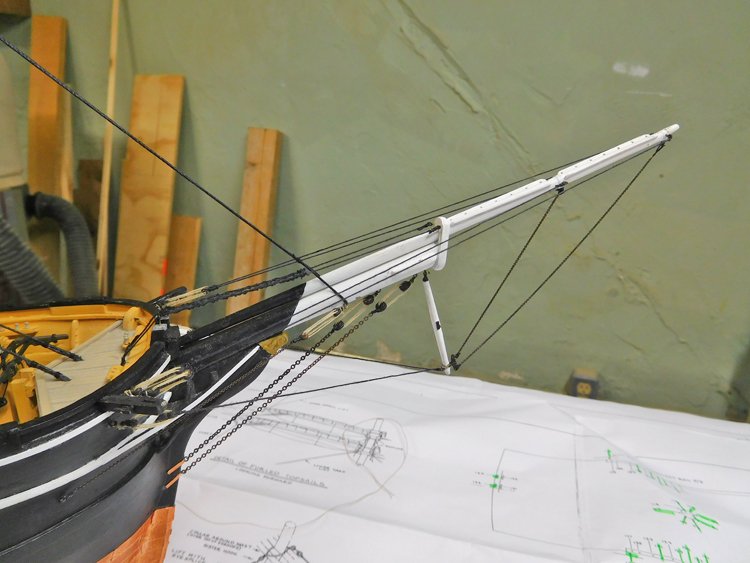
Good Morning, Yesterday I worked on the tricky martingale stays and finally managed to get an acceptable result - The challenge was cutting the two chains on the fore side of the dolphin striker to the right lengths to maintain similar tension in each one. It took me two attempts and the secret was to install one chain first, then install the two lines running aft of the dolphin striker. (I always used to secure and fix one end of such a line to the eyebolt first and then try to adjust tension through the deadeyes and lanyard on the other end. I now think it's easier to secure and fix the lanyard first and then adjust the tension through the seizing at the eyebolt end.) Then lastly I attached the second chain by eyeballing its length and cutting it a fraction long. I had to reduce its length by a couple of links before I had it right. This was a slow process, but not quite as difficult as I had anticipated. There is plenty more of this chain to be installed on this model, so it's going to be an interesting learning curve. David
.JPG.00de8c2938792625eb422e073961c3da.JPG)
.JPG.2ce5073d83fba7d1452ad652e7bc4b12.JPG)
- 145 replies
-
- 9
-
-
- model shipways
- charles w. morgan
- (and 1 more)
-
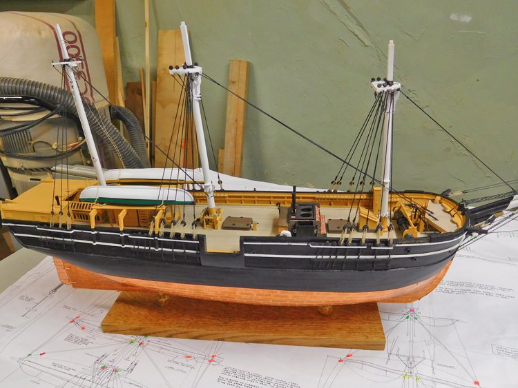
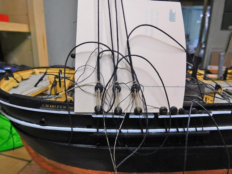
Hello Everyone, A bit more progress to report. I've been working away at the masts and yards and have them almost finished. There's a lot of iron work to be attached to these yards, and every time I look at the plans I find another piece to be added. I'll do as much as possible on the bench before mounting them on the model. The next picture shows how the lower masts will eventually be attached. I've also started rigging the bowsprit. Some of the stays and shrouds are chain. The larger size (bobstays) isn't too hard to work with, but the smaller stuff is very difficult to seize nicely to the deadeyes and eyebolts. It's possible to get a piece of .02" line through the end link, but it takes many attempts and much attendant swearing. I guess I could use finer thread, but I want the connection to have some strength and security Where the chain terminates with a deadeye and lanyard it isn't difficult to get the length right because there is some adjustment possible in the lanyard, but I am worried about attaching the two martingale stays as they both run from jibboom to the the dolphin striker and are attached directly without a lanyard. There isn't room for any adjustment. If there was just one on the fore side of the dolphin striker it wouldn't be too bad, as I could adjust the tension with the line running aft to the hull, but there are two of them and they will have to fit perfectly in relation to one another and I haven't quite figured out how to make that happen. Anyway, that's all for now. Many thanks for comments and 'likes' David
.JPG.7b07cc41fdb10110ad21d7580bd4281e.JPG)
.JPG.9092866f55b8e8bcb49a4a4d91a9c0a5.JPG)
.JPG.4d4d310eeff98b2d025fea36e04d959a.JPG)
.JPG.5da58ef78116d1ed340b576f4a10fd42.JPG)
- 145 replies
-
- 12
-
-
- model shipways
- charles w. morgan
- (and 1 more)
-
A little progress to report - I've finished attaching the lower deadeyes and chainplates which more or less finishes the hull. The boat davits and cutting in stage have to be added, but that will come a little later. I had previously made the bowsprit assembly, so have now installed it along with the dolphin striker. I'm not very comfortable making small brass components, but I managed to get an acceptable result for the fitting at the bottom of the dolphin striker. I've been working on shaping the masts and yards which are now all done and the enormity of the task of assembling them all is just now beginning to dawn on me. There is a lot more hardware on these spars than I have ever encountered in my previous models. I guess it's related to the time period of the ship. All my others are late18th century and this one is mid 19th century. The questions are (a)- how to attach it and (b) when is the best time to attach it. The three lower yards on the fore and main mast are attached with metal brackets, but how to attach them. On the real ship iron bands with flanges on the aft side wrapped around the yard and the bracket was attached with a pin. I guess the most correct way to attach these brackets on the model would be to wrap a small brass strip around the yard, bend the ends into flanges and drill a hole through them. I just know that there is no way I could do that in a neat and attractive way, so I am developing an alternative solution. I filed two grooves around the yard and will attach the bracket by threading wire through its holes and then wrapping it around the yard in the grooves so that the wire lays flush with the surface of the yard. Some glue will secure the wire in place and then I'll wrap a small strip of construction paper around the yard simulating the iron band. Then the whole thing gets painted white. Now I just have to figure out something similar for attaching it to the mast. There are dozens of eyebolts to go on these yards and I never know when to attach them. It's always easier to do on the bench before mounting the yard, but if a line has to be seized to the eyebolt later, that's hard to do after the yard is mounted. If I attach all the lines to the eyebolts before mounting the yard then I end up with a real mess of lines which always gets me into trouble. Perhaps the answer is to drill the holes and place the eyebolts without gluing, then after the yards are mounted, take them out one by one to seize the line to it and then glue it in place. I will ponder this some more over a cup of coffee. It's 3 o'clock which is my coffee time (even though I'm retired I take prescribed coffee breaks at 10 am and 3 pm as if I actually needed a break from anything - old habits sometimes really hang on.) David
.JPG.3500dcfa51857710a6e29bdbc38be2db.JPG)
.JPG.607f83d0bef5a974c777f1fb0bc76ad2.JPG)
.JPG.a30ae6087371acde19d8b6b911a21acc.JPG)
.JPG.a2c39862a3d3ffb2b9e777a3d51f604b.JPG)
.JPG.878673f34d27000d147363b9c330fef4.JPG)
.JPG.8d6b4a1c51adeb99c253d18d45fdd842.JPG)
.JPG.b024b6821bbe47d600e7490f4f39f2b4.JPG)
.JPG.bf1d6e21923fee737a6870a63ee1fc7e.JPG)
- 145 replies
-
- 10
-
-
- model shipways
- charles w. morgan
- (and 1 more)
-
Hi Dave, That beech looks great - it does suggest oak, but the grain is more suited to the scale than that of actual oak would be. Is it nice to work with, I've never used it. David
-
Jointer Switch Question
David Lester replied to David Lester's topic in Modeling tools and Workshop Equipment
Thank you! I just replaced the switch and it's working perfectly. Yet another reason to love Model Ship World! David -
Good Morning, I'm hoping someone can help me with the following question (which only arises due to my own stupidity.) The switch on my Delta jointer failed and after quite a bit of difficult locating the right replacement one online, it has arrived. My problem is, I didn't pay enough attention when I removed the old one and now I don't recall how to connect the four wires to the new one. Oddly enough, I haven't been able to find the information online. There are 101 different versions of a rocker switch and I can't seem to find a diagram or Youtube video that applies to this particular switch except for one which was of no help because the first thing it advised was to take careful note of how the old one was connected! Here's a picture of the switch along with my two connection options. I believe that the bottom diagram is the correct way. If anyone can confirm that I would be most appreciative. Many thanks, David
-
Hi Bruce, Great looking model and beautifully done! David
-
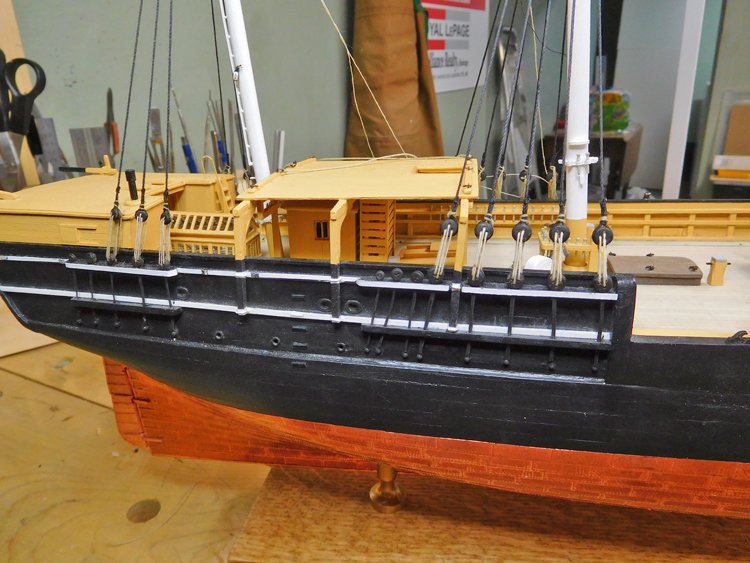
Hi Everyone, I've been working away on my Morgan (when not shoveling snow!) I'm working on the various hull details. With all models I know it's necessary to think several steps ahead but that's really the case with this one. I installed the anchor deck, but in order to do that the main stay has to be first located. In order to get the angle right, I needed to put the main mast in place to get the starting height of the stay and to located the holes in the anchor deck in the right spots. Then I started in on the hull details which is a very tricky endeavour. There are many components to be added along the length of the hull and it requires quite a bit of careful layout to get them more or less right. I've been marking the locations of davits and various other things with masking tape: I started with the canopy supports - I've made the roof, but it's not actually installed; I'll do that later. I'm currently working on the channels and chain plates and had to do some experimenting and have had a few false starts. The plans show one continues piece of wire wrapped around the deadeye at the top and forming an eye at the bottom. I found it difficult to make them look half decent and almost impossible to control their lengths. So, I wrapped the wire around the deadeye, soldered it and left the ends loose. Here they are in place just to gauge their length (they're still rough looking at this point and I scrapped a couple of them): I then cut them to length and soldered an eyebolt to the bottom end. This works very well as I can fine tune the length if need be by sliding the eyebolt up or down and resoldering it. Here's one after a little refinement that should look just fine when installed and painted flat black: I started with the mizzen channels as there are no other components to interfere with them and I'm still fine tuning them. The main and fore channels have to be fit around davits etc. so that's next on the agenda. Thanks again for looking in David
.JPG.13fc664230499e1fea7071b609551f19.JPG)
.JPG.64443369060caf6bdf94e1262cc7ea3d.JPG)
.JPG.16a3ff2860571e61484bdaa8e846dcf7.JPG)
.JPG.8563874006d91aa9afd9107daa306387.JPG)
.JPG.490d3e40f1e15a12c3f886d94d2adca7.JPG)
.JPG.8d34e22e73683f2eb75793744338bd62.JPG)
.JPG.6180d2fae16abc5fe7e609d7a611e39e.JPG)
.JPG.4238b91d4caa9520b6136c16d44ac704.JPG)
.JPG.b010787b2ddb32988f144aa1e1e688b1.JPG)
- 145 replies
-
- 13
-
-
- model shipways
- charles w. morgan
- (and 1 more)
-
Hi Jim, Have you tired Cornwall Model Boats? These look like they might do the trick. Cornwall Model Boats | Model Boat Fittings | Artesania Latina Fittings | Cannon Shot | AL8659 Cannon Shot 2mm (100) David