ccoyle
-
Posts
10,604 -
Joined
-
Last visited
Content Type
Profiles
Forums
Gallery
Events
Everything posted by ccoyle
-
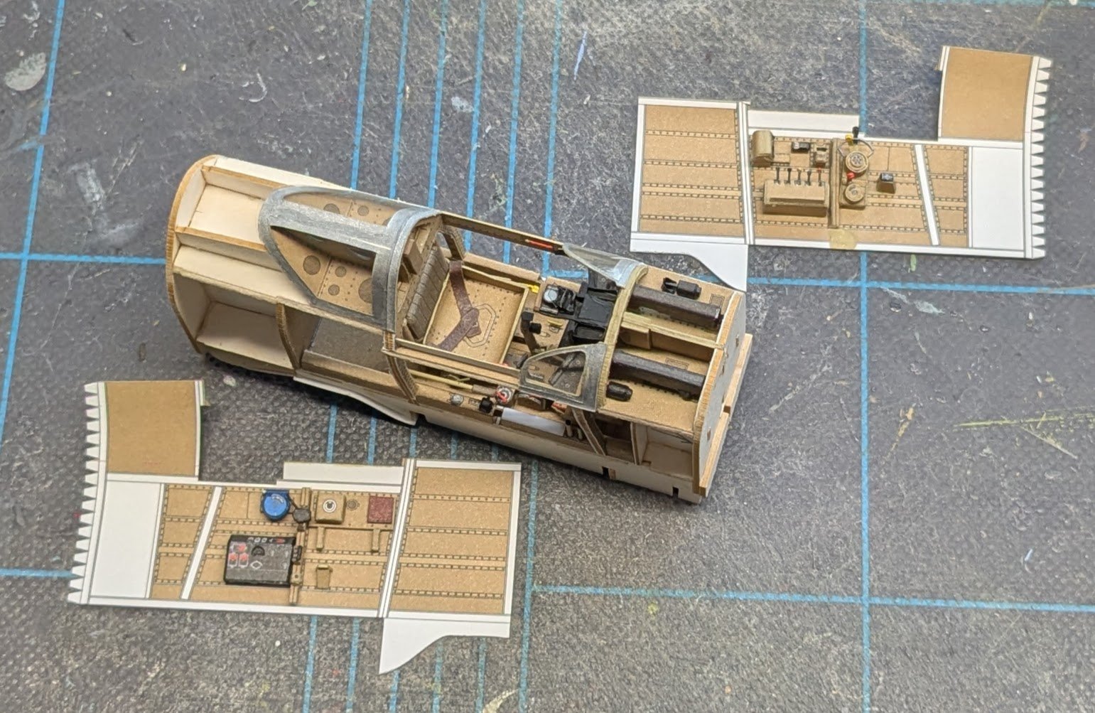
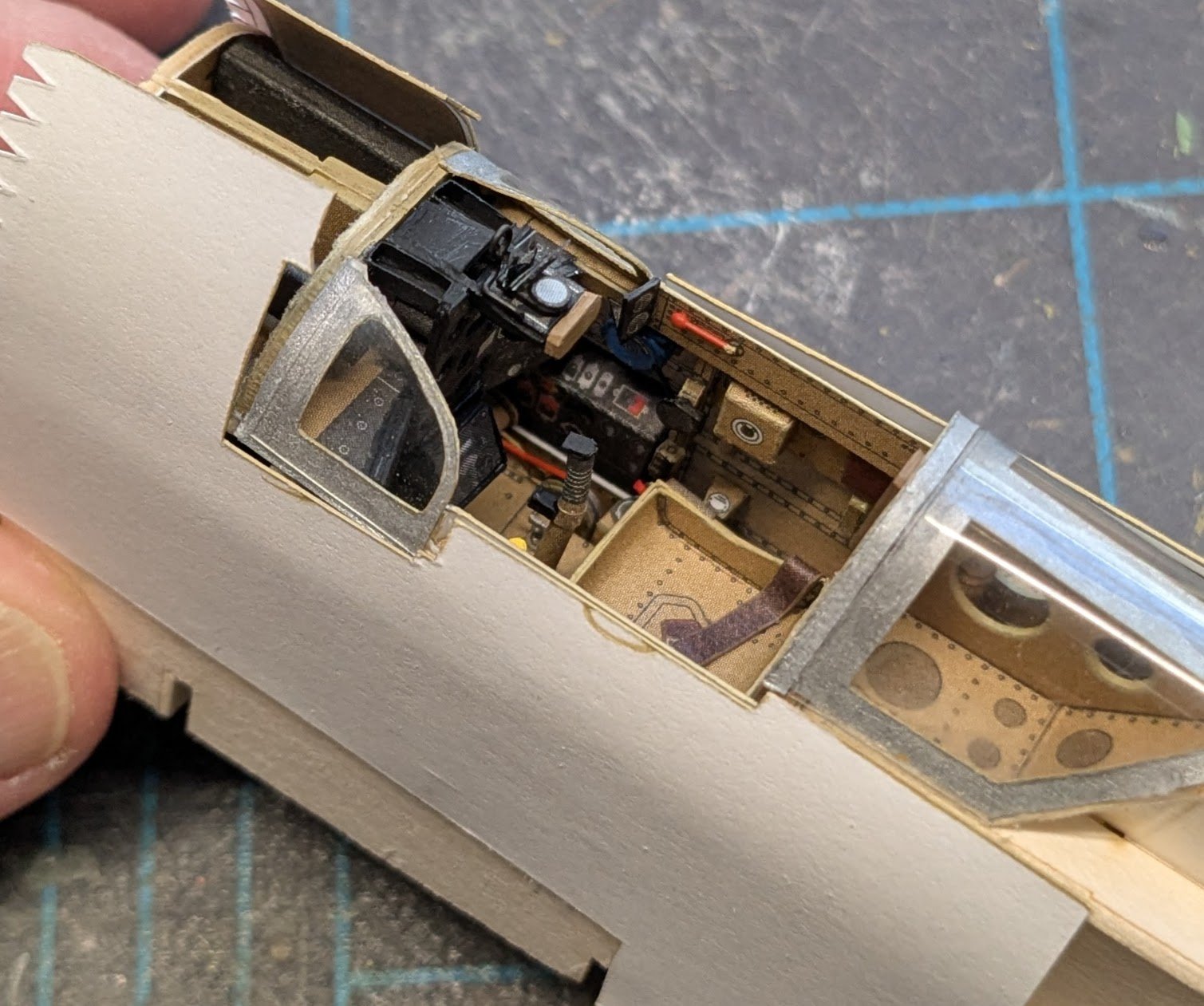
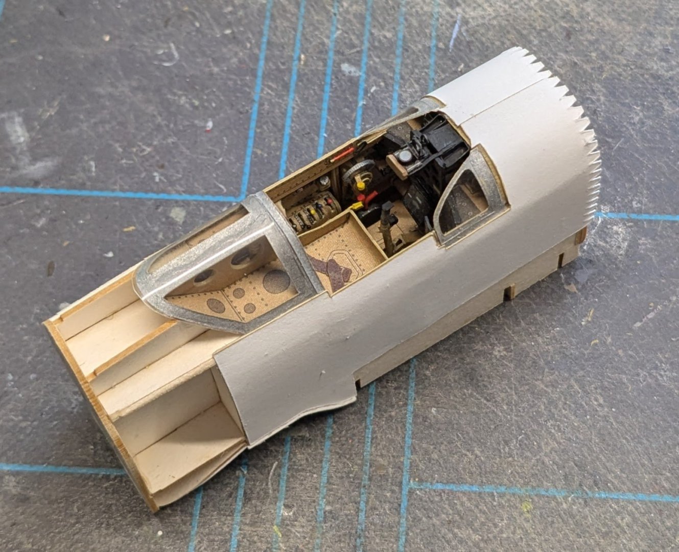
 Big milestone today! Take a good look, because it's now time to zip up the cockpit. At long last we can work on something different for a change! The forward fuselage framing is next. Cheers!

- 102 replies
-
- 17
-

-

-
Joelle, every time I check on your build, I am blown away by your skill. I'm curious if you have any plan in mind for having this model on display somewhere once it's finished, other than a shelf in your house somewhere. It seems eminently worthy of a public display somewhere, even if it is not a scratch build and thus not up to some museum standards.
- 217 replies
-
- 4
-
-

-
- Russo-Japanese War
- Mikasa
- (and 2 more)
-
This topic will give you some ideas on how the finished gratings should look. I'm assuming you're using the typical interlocking combs supplied in kits. The important part to remember is that the fore-and-aft pieces (the battens) ride on top of the athwartship pieces (the ledges). Also, the finished grating should always fit within its coaming so that the coaming's inside edges abut a batten or ledge; the edge cuts should never be made through the grating gaps themselves. Cheers!
- 1 reply
-
- 2
-
-
I used it almost exclusively back in my early days. It does the job well, though it is thicker than the canopy glue I prefer these days. Since it is water-based, it can easily be thinned to whatever consistency one likes.
-
Congratulations, Russ, that is really some very nice workmanship!
-
#4 is not an option. Even incomplete builds can be useful to someone looking for information on that kit. In your case, I'd go for #3. Everyone understands that there are reasons why someone might lose interest in keeping a log updated, but it'd be nice to see the finished model and be able to mark your log with the highly-prized "finished" tag.
-
This is why I never, ever let my guests backlight my models when viewing them! 😂 offset printing
-
I found the review. It's in the March/April 2006 issue of Ships in Scale, Vol. XV No. 2., page 92. The author rated the kit's written manual 2.5/4 and photo manual 4/4. Overall he had this to say: The kit's final score was 2.5./4. Keeping in mind that the review was written 20 years ago, I think it's safe to say that the Constructo kit was similar in overall quality and design to other kits of that era, but that those designs are typically dated in comparison to what's available today. Cheers!
-
Every time I see a cool plastic kit being started up, and it's a subject I have in my card stash, I always feel the urge to start another project! 😂
-
Novice: AL Sanfrancisco II or OcCre San Martin?
ccoyle replied to Arnie-75's topic in Wood ship model kits
Welcome, Arnie! The first question to ask is: do you really like these particular ships? You'll be making a significant time investment, so liking your subject is important. Second, whereabouts is "here"? Access to kits can certainly affect your decision, but if we know where you are located, we may be able to suggest some alternatives for your consideration. Other members may chime in with more kit-specific comments. Cheers! -
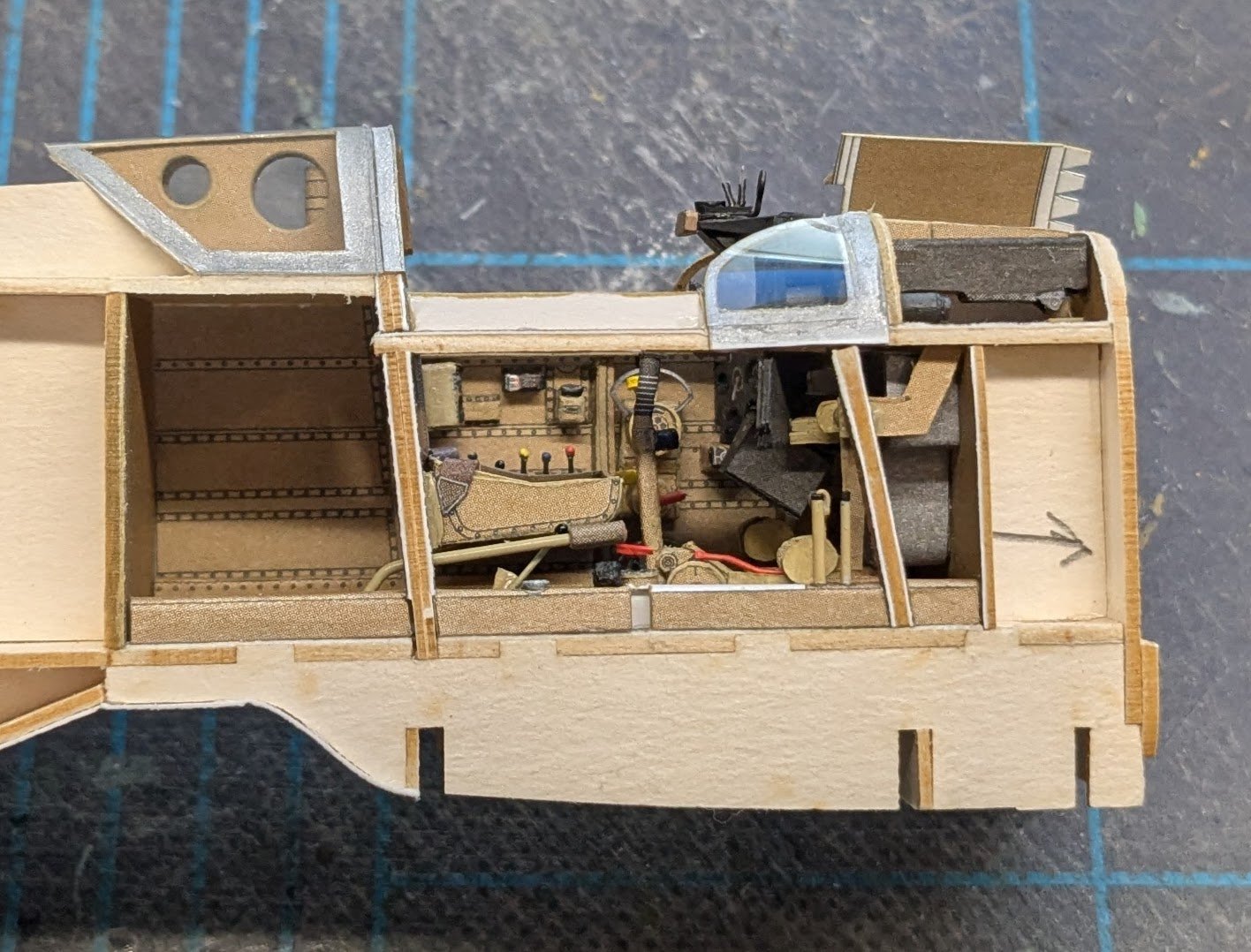
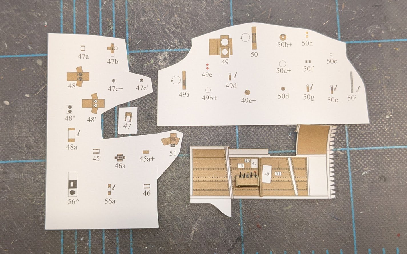
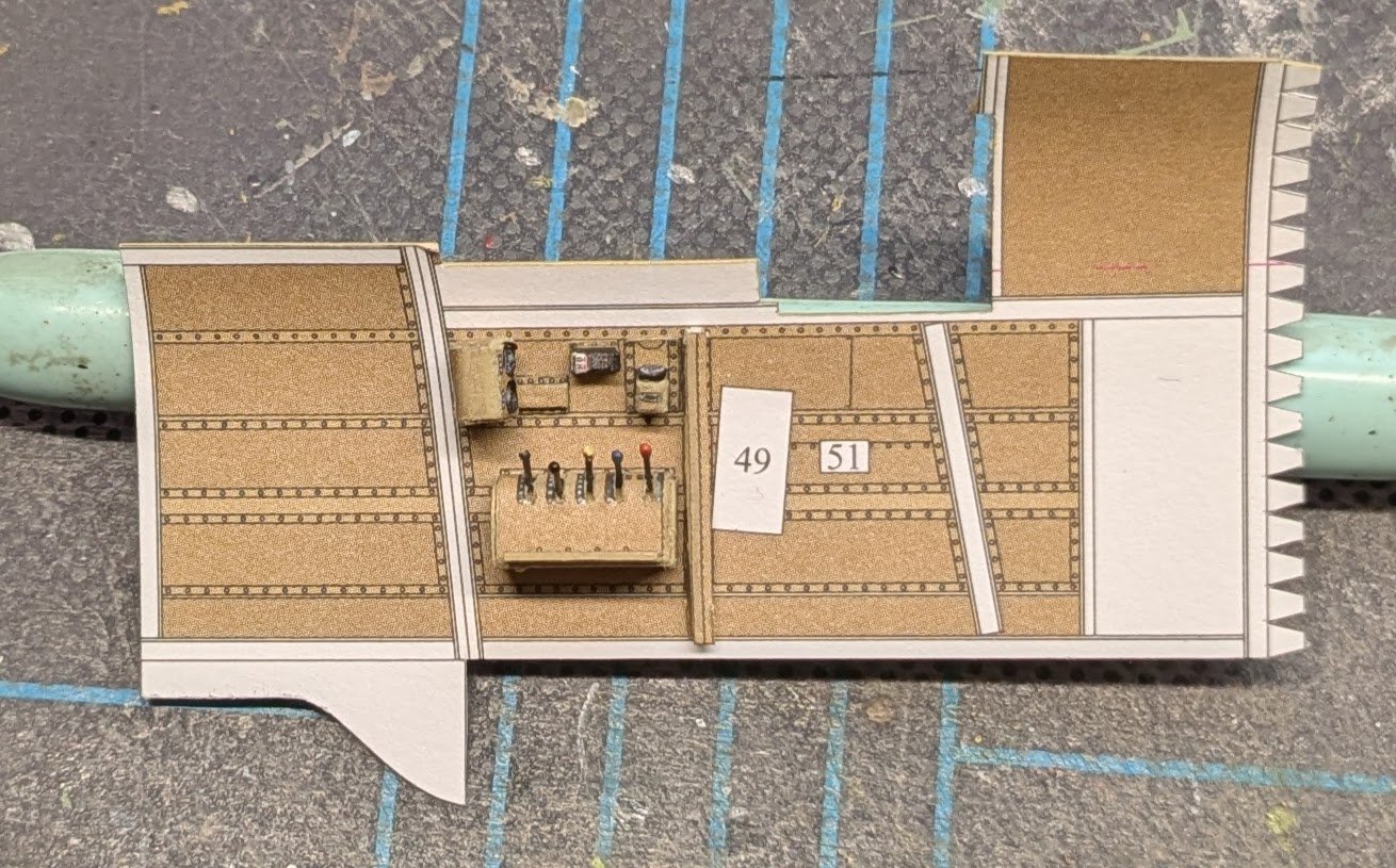
Here are the remaining port-side cockpit parts. Fun, eh? And here is half of the port side completed. Onward!
- 102 replies
-
- 17
-
-
Johnny has provided a great overview of the kit. I remember maybe twenty years that one of the modeling magazines (might have been Ships in Scale) did a review of the newest Constructo version available at the time, and the reviewer's verdict was that it wasn't a bad kit for the money and represented a step up in quality compared to earlier Constructo kits. That being said, I don't think you'll get much argument against the Constructo kit being several steps down from the Caldercraft kit, and even the Caldercraft version is a bit dated, since kit design in general has advanced significantly in recent years. Cheers!
-
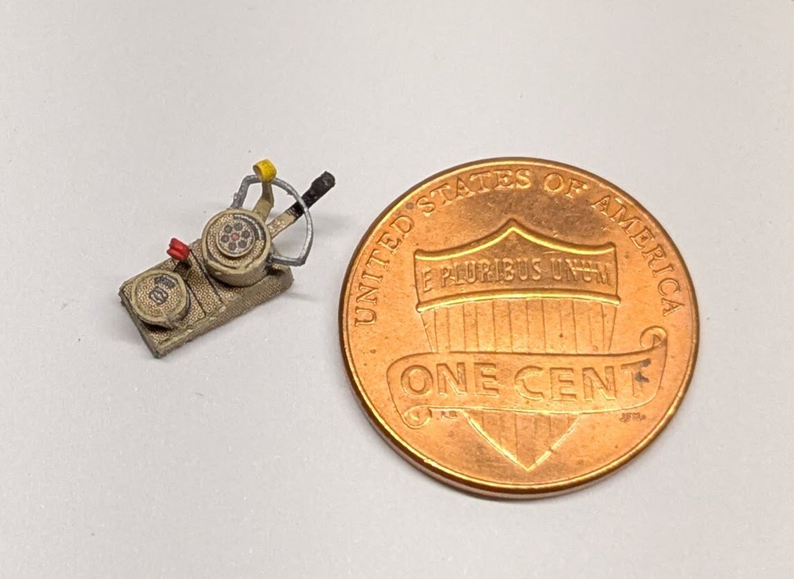
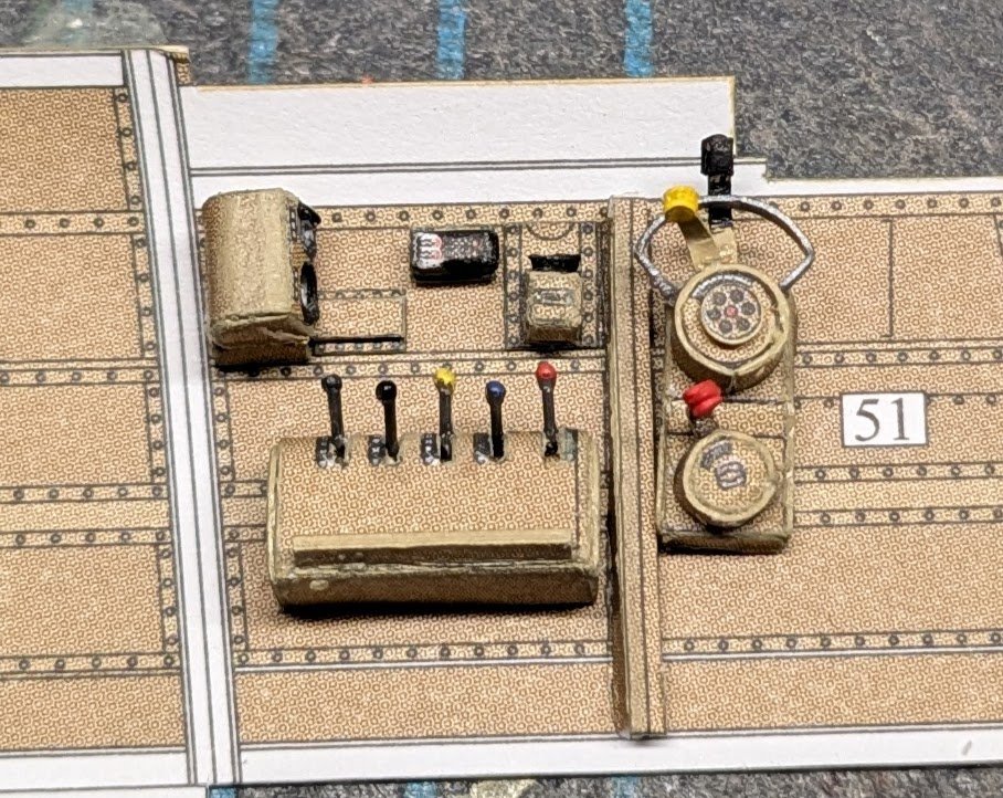
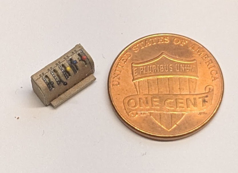
Remember the old adage about treating every sub-assembly as a separate model? Takes time, but it works. Here's a bank of setting levers. What do they control? No idea. 😂 Merry Christmas to all of you merry model makers!!

- 102 replies
-
- 14
-
-
-
That sounds like a fun job!
-
Vought F4U Corsair by PeD - Tamiya - 1/48
ccoyle replied to Danny_CZ's topic in Completed non-ship models
Amazing work and a great memory of your Dad! Thanks for sharing! -
Arado Ar-196 by Ian B - FINISHED - PLASTIC - German seaplane
ccoyle replied to Ian B's topic in Non-ship/categorised builds
Fabulous! As I posted before, you've made her look just as of she has done some hard shipboard service. -
If you end up being unhappy with the final result, you can always opt to fill, sand, and paint. This is how some of our Polish friends produce their immaculate hulls. Of course, most of them seem capable of producing immaculate hulls without the extra effort, so there's that. 😋
-
Technics to attach the sails to the yards
ccoyle replied to Amedeo Riga's topic in Masting, rigging and sails
The nautical term you are looking for is bending. Sails were bent to yards in various ways depending on the type of sail, era, and nationality of the vessel. If you can provide those details, our members may be able to direct you to some resources. -
Welcome aboard, Rui!
-
@SaltyDog Your photos are not showing. You may need to convert them to a different file type, such as a .jpg. Most members will not bother clicking on links.
-
Welcome aboard! You'll probably want to message @James H about closing your old account, if it still exists.
-
Welcome aboard!