ccoyle
-
Posts
10,587 -
Joined
-
Last visited
Content Type
Profiles
Forums
Gallery
Events
Everything posted by ccoyle
-
 Agree -- nice work!
 -
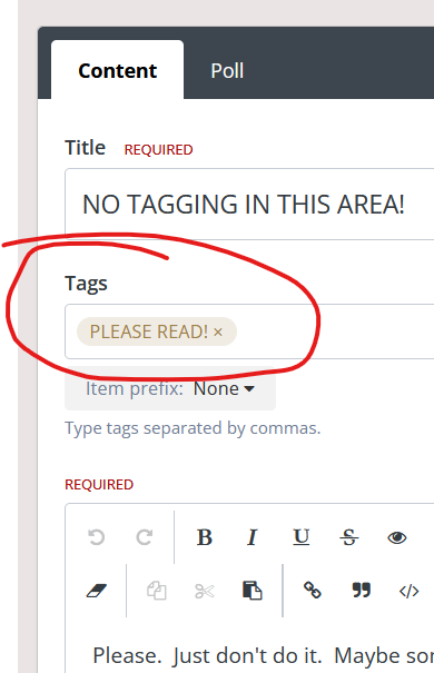
It's a clickable identifier that you can add to the first post in a topic -- except in this area, of course! Clicking a tag brings up a list of all the topics that have that same tag. Here, for example, is the tag that was created for this topic. Additional tags are added by typing in some text in the box and hitting 'enter'.
-
Very nice result!
-
Rick, If you'd like to get a sense of what is available in the card ship market, take a look at the first few chapters of our card modeling tutorial here. There's a discussion of the major publishers and vendors. Getting products into the US is a little dicey at the moment, given the current tariffs environment.
- 43 replies
-
- 1
-

-
- card
- Speeljacht
- (and 2 more)
-
D7E Bulldozer by RGL - FINISHED - Hobby link - 1/35 - 3D-printed
ccoyle replied to RGL's topic in Non-ship/categorised builds
I hit the "wow" button because not only does your model look exactly like a well-used dozer, but you did it in only three days. Amazing! -
Finnarctis was sailing under the name Alouette Arrow as of 2019.
-
Pictures and location of item would be helpful.
-
I have a similar issue with some of my card airplanes. After they've sat on a shelf for several months, I sometimes notice that the landing gear have sagged. I don't usually have much motivation to repair them. My modeling mojo tends to regard finished models with a bit of indifference.
-
The answer to that question depends in large measure on what kinds of ships tickle your fancy. Men-of-war or merchantmen? Lots of rigging or little? Ancient or modern? Knowing what you like will help narrow the field of candidates.
-
Welcome aboard, and nice work!
-
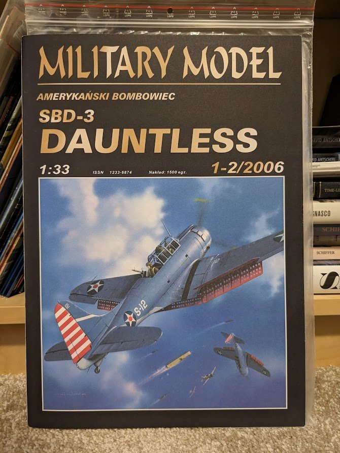
Already have one -- but don't ask me to build it next! 😉 The kit depicts the aircraft flown by Ensign John Leppla of VS-2 (USS Lexington) at the Battle of the Coral Sea. Leppla and his gunner accounted for seven Japanese aircraft.
-
I have a short list of kits that I would probably snap up if they were to be published by one of my favorite publishers or designers: Devastator, Corsair, Avenger, Swordfish, Dr.I, S.E. 5a, SPAD XIII, Albatros D.III/V. Most of these do exist in kit form, but they are either old kits with poor graphics, the work of designers I don't trust much, or electronic downloads (I prefer the offset-printed kits). Kartonowa Kolekcja just released a new kit, but it's a repaint, a Fokker D.VII in Polish markings that is almost entirely covered in lozenge camouflage. In the first place, I just built the original kit a few months ago, and secondly, instead of one of the many colorful D.VIIs that could have been published, we got lozenge. 😑 No, thanks. But -- we can only pick from what the publishers offer!
-
Welcome aboard, Gus!
-
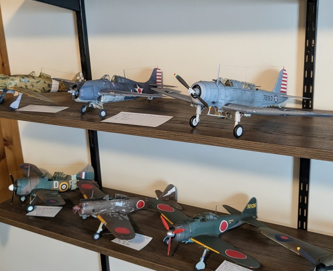
The Big Reveal! So, this one is officially done! Not much to say in conclusion except that this is another simply wonderful kit from Pawel Mistewicz and Kartonowa Kolekcja. The diagrams required some pondering here and there, but on the whole this was a relatively pain-free building experience -- a kit that can be heartily recommended without reservation. Enjoy the pictures!


- 92 replies
-
- 26
-

-
-
I have a plan. Of course, the plan changes hourly, so it's not particularly useful. 😅
-
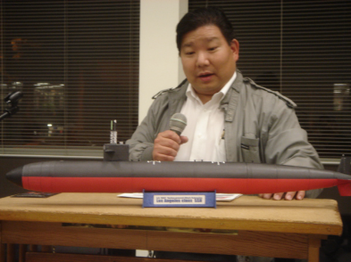
I just found out this morning that NRG member David Okamura has passed away. You may not know of him, but if you have ever enjoyed any of the card model builds I have shared here at MSW, then you owe a small debt of gratitude to David -- he's the man who got me started in card modeling. I first met David at a meeting of the Ship Modelers Association (they met in Placentia, California) about twenty-five years ago. He was already a very skilled card modeler at the time, and when I saw his models at the club's show-and-tells, I said, "Wow, I can't believe that's made out of paper!" Sound familiar? David almost always had a new model or two to show at the meetings. He often did beta builds for designers, and if you had ever had the chance to admire his work, you would understand why those designers sought David's assistance. I decided I had to try a card model, too, and that was all it took to get me hooked. So, if any of my models have tempted you, or perhaps even persuaded you, to try a card model, it's partly thanks to David's having persuaded me to try one. Rest well, friend. David showing one of his models at a 2009 SMA meeting
- 1 reply
-
- 18
-

-
-
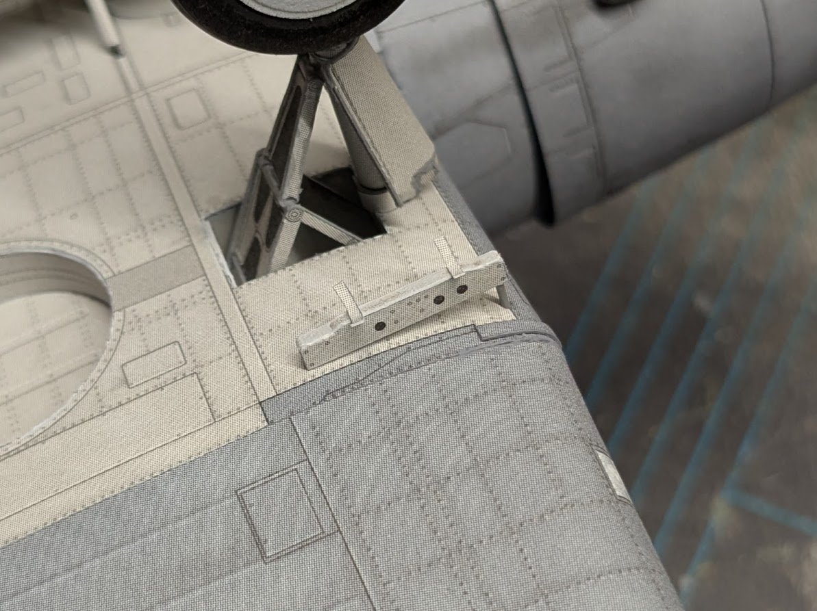
The SB2U had a shackle under each wing to carry two additional 100 lb bombs. Believe it or not, there are only three tasks left to complete on this model!
- 92 replies
-
- 16
-
-
-
The shackles are simple card rectangles wrapped around lengths of wire. Only the center portion of the shackle is "load bearing" (if that is true in any real sense), i.e. the center piers are glued to the depth charge on one end and to the fuselage at the other end. The outer bits of the shackle are just cut to length and fitted afterward, held by spots of glue.
- 92 replies
-
- 11
-
-

-
It really helps that a depth charge is a basic cylinder instead of being rounded at both ends!
-
Gotta remember that in the early 20th century, wood carvings were still common architectural features, so professional carvers would not have been so rare as they are in our modern age.
-
An interesting and poignant subject, but when I reflect on the facts that the first crewed shuttle flight was in 1981 and the last in 2011 (already fourteen years ago!), I feel a bit old!