NMBROOK
-
Posts
2,305 -
Joined
-
Last visited
Content Type
Profiles
Forums
Gallery
Events
Everything posted by NMBROOK
-
 Thank you very much indeed Matti and Pete for you kind words Kind Regards Nigel
 -
Looking good Patrick,excellent work Spending additional time at this stage and resisting the temptation 'to throw some planks on' pays dividend in the long run.I may be in the minority as I actually enjoy planking but only if I am confident everything is right beforehand. Kind Regards Nigel
-
Thank you very much indeed Brian,Grant and Keith Brian when I priced up the plans and castings,there wasn't a big difference in price to the complete kit.I was unsure at that point whether I would use the castings.If I did it meant more sense just to buy the lot.Should I not use the castings,then I will essentially have a complete kit to sell on minus the bulkheads.I could always offer to cut a set of these for any prospective buyer<Royal William is a different matter,the difference in price is massive!!As you know I already bought the plans but the casting set is not much more than Mordaunt's!Castings and plans will work out at roughly 35-40% of the total kit,so I will save a lot of money as I wouldn't use the supplied timber and most of the fittings. Keith,yes,there will be a section between the upper wales unplanked so the frames are visible. Kind Regards Nigel
-
Thank you very much indeed Mij and Blue Ensign for your kind words Kind Regards Nigel
-
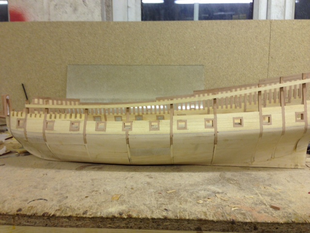
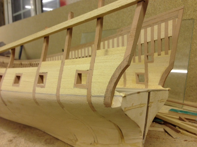
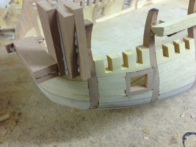
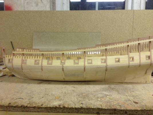
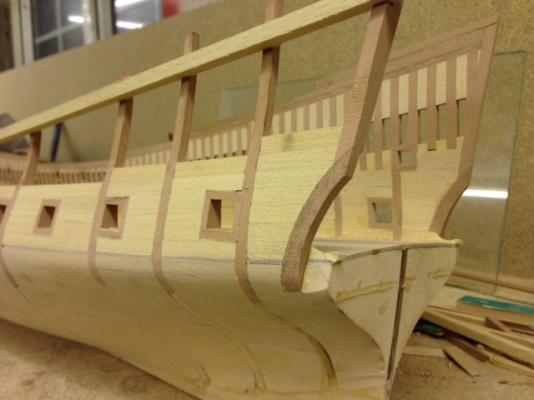
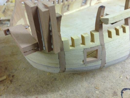
Work is slowly progressing on the port side.As I have proved everything on the starboard side,this acts as a template for the port side.This has enabled me to fit the gunport frames earlier in the process to make it easier to shape the internal profile.The handy thing with the gunport design is that tweaks are easy.Some of the holes for the linings have been adjusted and boxwood veneer shims used to ensure perfect alignment when sighting down the side of the hull.I have also been able to fit the lower counter side timber earlier than before.The rather random looking pear blocks at the bow are for shaping to match the other side.The are placed to ensure adequate material to carve the shape out of. Kind Regards Nigel

-
Deck beam Scarphs?
NMBROOK replied to NMBROOK's topic in Building, Framing, Planking and plating a ships hull and deck
Hi Wq I too find the whole structural design aspect of shipbuilding fascinating.My preferred period of the late 17th Century being a 'grey area' for reference material,I think necessitates some understanding of how things 'worked' in order to make a 'feasible' reproduction in the absence of full detail drawings.I think the keelson if different in that it acts as a clamp to hold the base of the frames (riders) to the keel.On thing I cannot get my head around is what determined where columns were placed.I know that they weren't present under every beam,but what rule governed which?Looking through my material last night revealed no answer.Aligning the columns to act with the knees would make sense,but if this is true,none of the author's of my books have stipulated that is the case. Kind Regards Nigel -
Deck beam Scarphs?
NMBROOK replied to NMBROOK's topic in Building, Framing, Planking and plating a ships hull and deck
Totally in agreement Wayne,it is interesting though the French chose to do their scarphs differently,however they did employ far more sophisticated technologies to ensure lower hull stiffness.Gaeton's Fleuron is an ideal showcase for this. Kind Regards Nigel -
Deck beam Scarphs?
NMBROOK replied to NMBROOK's topic in Building, Framing, Planking and plating a ships hull and deck
This is fun Wq 3296,when I say random,I mean occuring on random beams,not placed randomly on a beam.The scarph joints,whether single or double would be equal about the centreline.Coming from a structural engineering background,I hear what you are saying.In this instant the camber is radial and to allow water to drain off and does not drop out.I do know what you mean having built several bridges with Parabolic cambers that allow the structure to deflect to almost dead flat under load.The supporting structure of the deck,columns and hanging knees was designed to minimise any movement in the athwartships plane.I would say that cutting the scarphs horizontally would result in a weaker beam in the vertical plane,but that is just my opinion.If anyone fancies a go at finite element analysis then feel free The main problem being with a tapered scarph is varying amounts of material either side of the beams neutral axis. Kind Regards Nigel -
She is coming on great Nils I do agree the modification to the stern counter does balance things up better Kind Regards Nigel
-
Hi Patrick,yes the deck beams will be natural wood.Just to clarify,the pieces are not going to be glued together,I am just doing two at once to speed the operation up Kind Regards Nigel
-
Deck beam Scarphs?
NMBROOK replied to NMBROOK's topic in Building, Framing, Planking and plating a ships hull and deck
That is a good point Druxey,both Lennox and Mordaunt were built at Deptford which was experiencing some timber supply issues at the time,this is covered in Richard Ensor's book.This could well explain his decision to include some randomly placed scarphs.I think if I follow suit and include some,but not on every beam Kind Regards Nigel -
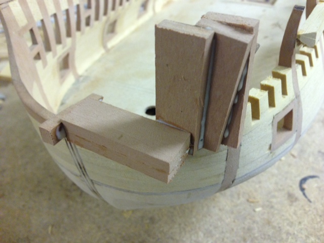
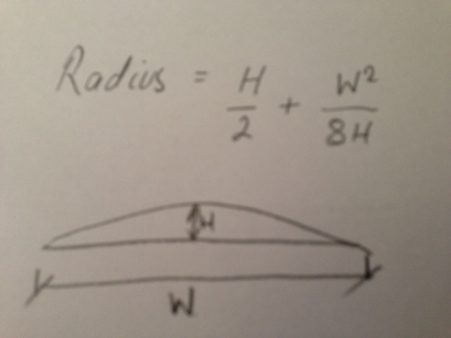
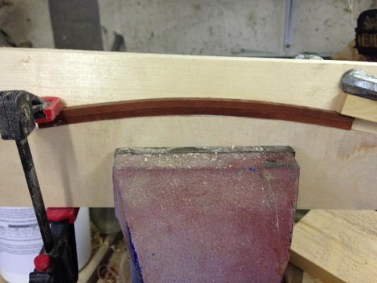
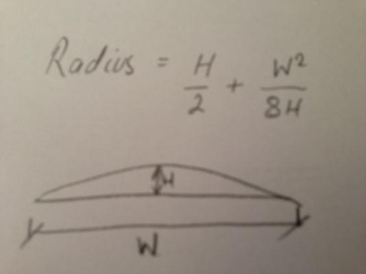
Just a small but nevertheless important update.I am currently working on the other side but doing a little multitasking In my last timber delivery,I had ordered some 6x4mm pear strip to see how successful it would be to bend the deck beams as apposed to cutting them.As a mentioned before these will penetrate the sides of the inner hull 'shell' and in effect be solidly anchored at the ends.I made a simple jig up to clamp the thoroughly soaked Pear strip in(tip here,soak until the pear no longer wants to float).I deliberately made the jig for double the camber to allow for some springback.Not only this but it is better to overbend and straighten rather than underbend.The radius was calculated using the formula shown in the pic.I thought i would include this as to my knowledge it hasn't been posted before.I clamped two strips in the jig at the same time on top of one another,Any more and it would start to make too big a difference to the radius.The question of whether these beams would be scarphed in the middle is in abeyance and I have posted another thread regarding this.Even if these will be scarphed,I thought it necessary to put the radius in before tapering as the bending properties would not be consistent with a tampered section. Kind Regards Nigel
-
I am posing this question for a second opinion.Whilst researching the deck construction for my Mordaunt 1681 build,I have come across conflicting material.Looking at the Lennox 'monograph',Richard Ensor shows deck beams with a single central scarph joint in some of the beams,however Peter Goodwin states that deck beam scarphing didn't start until well into the 18th century when large timbers became harder to source.Just thought I would 'throw this one out there' for other opinions.The largest span is around 8 metres. Kind Regards Nigel
-
Thank you very much indeed Brian In total agreement with your there mate,these kits are a 'kit bashers' dream I have probably got more enjoyment out of this build than any other!!.Already thinking of which one to do next but that maybe a while yet Royal William is definitely on the cards,but a serious think about whether to sell my plans and buy the complete kit or just get the castings from Italy is in order.I don't wish to embark on another mass carving project with that build,the only thing I would do is machine the windows out and fit boxwood frames Kind Regards Nigel
-
Thank you very much indeed Patrick I think the joint design and assembly procedure for the lower ports is something I shall carry forward and use on all my builds.Consistency to 5/100 mm is something I cannot achieve using traditional techniques. Kind Regards Nigel
-
water way?
NMBROOK replied to jhl's topic in Planking Techniques's Click Here for Topics dedicated to planking!!!!
The waterway sits directly inside the frame and on top of the deck beams and the shape of it varied considerably depending on the age of the vessel.The deck planking and spirketing both but up against it.The exposed face of the waterway started as a concave section for 17th vessels but moved to a convex shape,almost a rounded square in later ships.As Wayne says it's role was to avoid an internal corner that would be prone to water penetration.It is only in today's ships where there is actually a 'gutter' shape that channels water to the scuppers and then this mainly appears on the superstructure,where there is open railings and normally a 'kick flat' present. Kind Regards Nigel -
That is some clever work mate to achieve the spliced look with purely paint!!! Kind Regards Nigel
-
Thank you very much indeed Nataniel and Kester I am familiar with that one already Kester Kind Regards Nigel
-
How to sand longer stock?
NMBROOK replied to Landlubber Mike's topic in Modeling tools and Workshop Equipment
The cheap no thrills way I do this is to glue glasspaper to a long(at least 200mm) piece of wood.You get far more control than messing with a normal sanding block and if you make it long and narrow,you are less likely to 'dome' the face you are sanding. Kind Regards Nigel -
I agree with Demonburger,the problem being is the differences in what each builder may want out of a particular kit.It may be possible to do as marks out of ten for particular categories e.g.instructions,timber,fittings,plans,historical accuracy/actual existence etc but I do think it would be wrong to generalise. Kind Regards Nigel
-
WTG Tony!!! Outstanding work,it isn't very often I recommend something I haven't actually tried myself,but having seen it done and having machined Ebony I was confident it could work.Very well done indeed,the ebony version is by far the most impressive It would have been straight forward to make them in resin,but I don't think the detail would be as crisp due to the need for a two part mold. Kind Regards Nigel
-
My personal favourite is Navy Board Ship Models by John Franklin,had it 15 years and can still pick it up and read for hours 2,Restoration Warship-Richard Ensor 3,The art of shipmodelling -Frolich That is the top three out of about 100 books I possess on ships/shipmodeling. Kind Regards Nigel
-
Thank you very much indeed Grant And thank you for another alternative,we will be heading for a new thread in shore leave at this rate Kind Regards Nigel
-
Thank you very much indeed buddy I love that phrase,much more PC than the one I use Kind Regards Nigel
-
Thank you very much indeed mate!There are only six round gunports,the ports I have just installed will have carved boxwood wreaths around them which give the rounded look.I am in a bit of a quandry in that whilst the builders model does not show lids on these ports,the rebates are there to take them.I feel though for this period and the location on the vessel,they would be two side hinged 'doors' rather than one top hinged lid.Decisions,decisions Kind Regards Nigel