KeithAug
-
Posts
3,980 -
Joined
-
Last visited
Content Type
Profiles
Forums
Gallery
Events
Everything posted by KeithAug
-
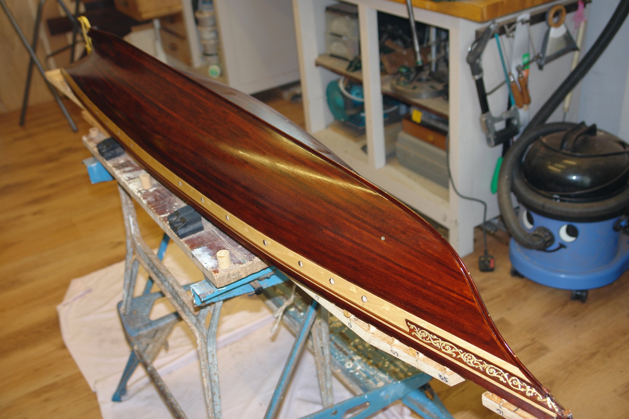
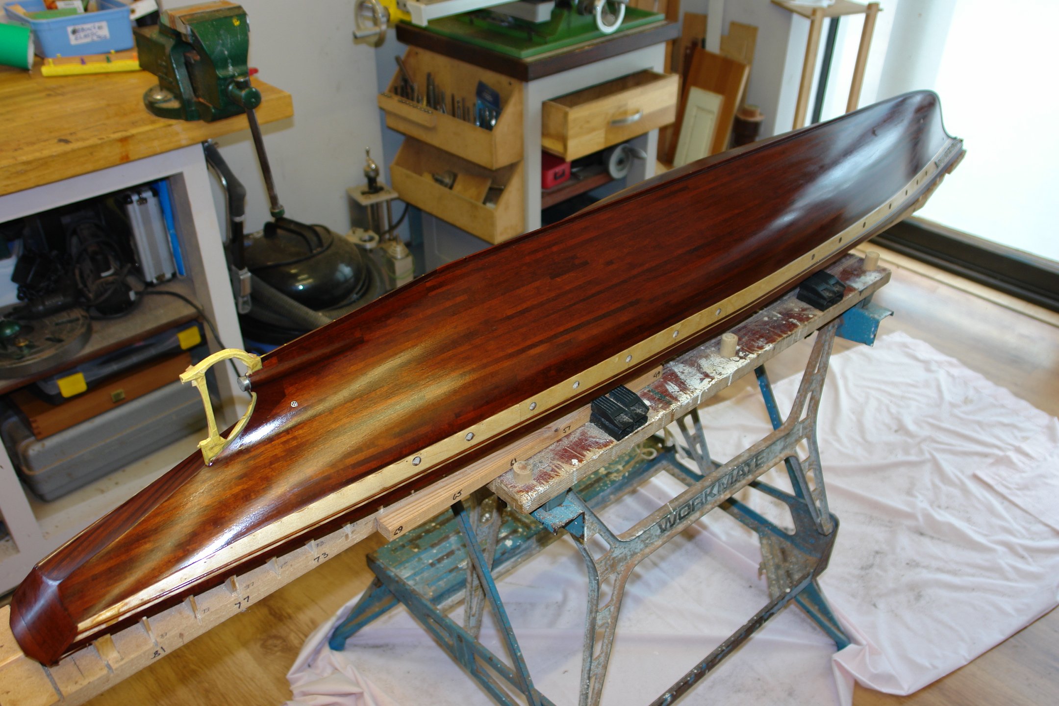
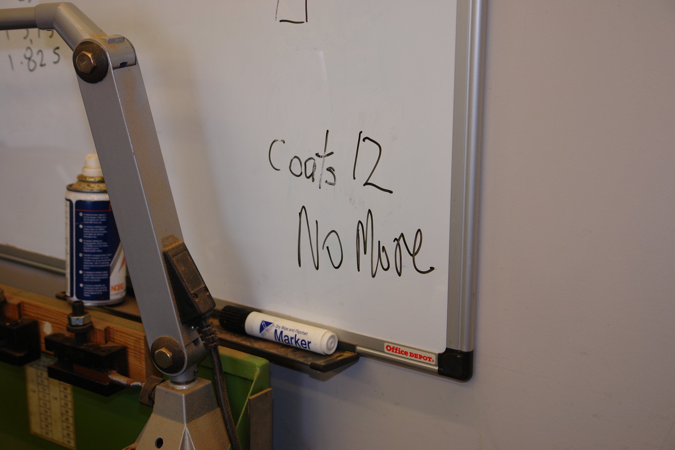
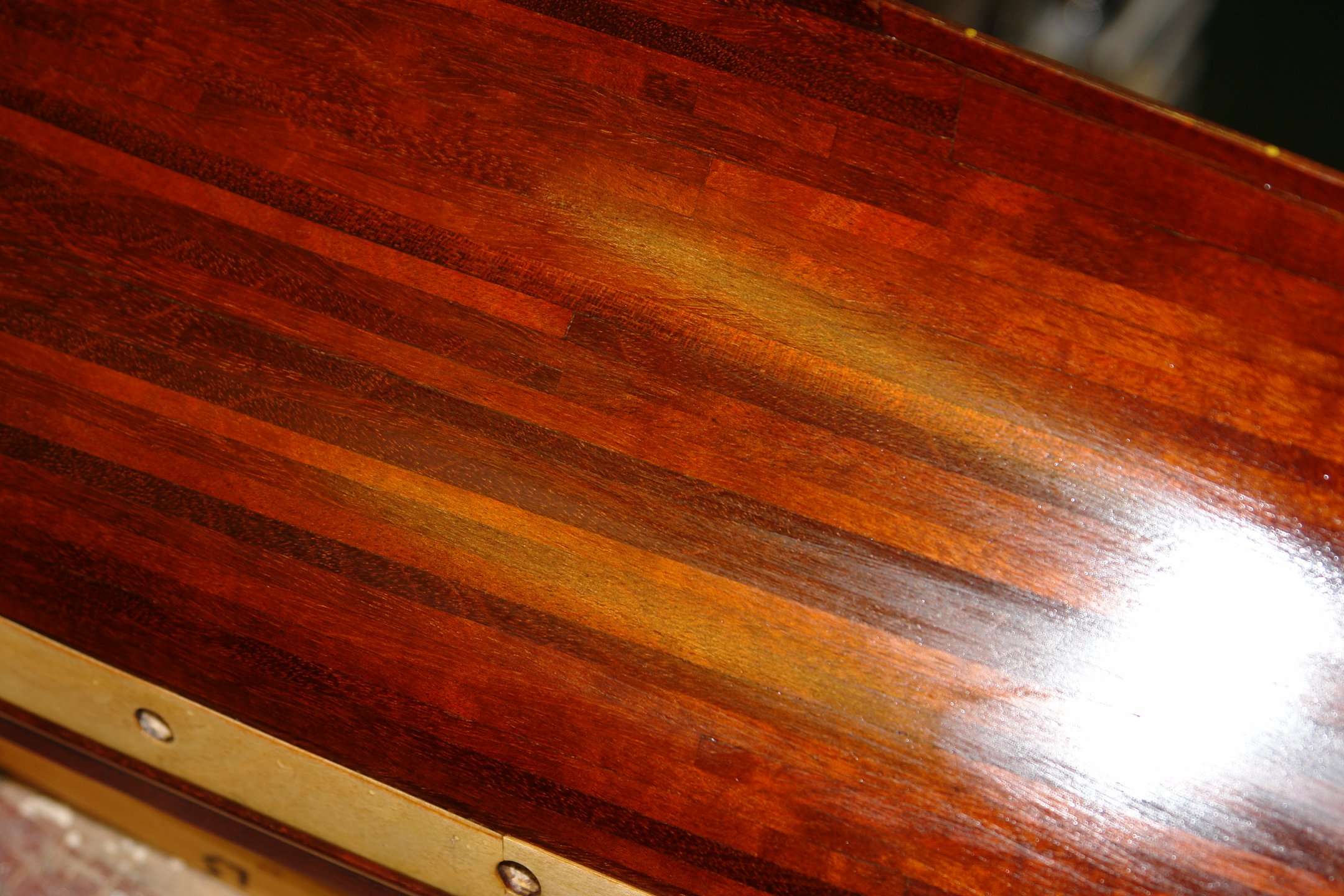
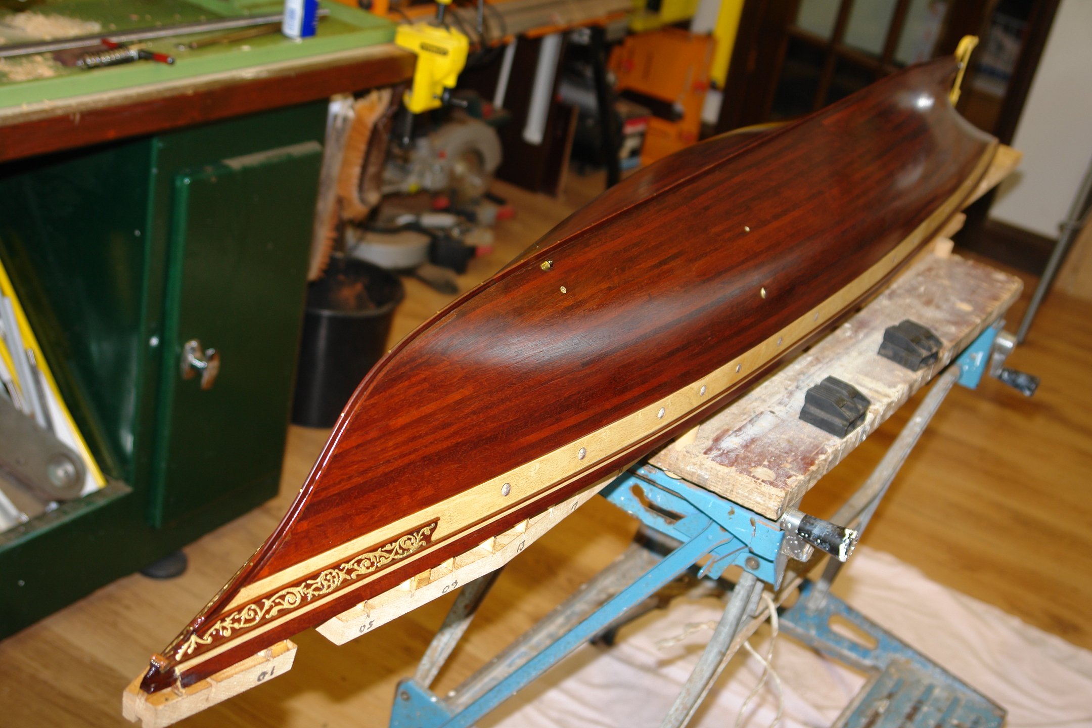
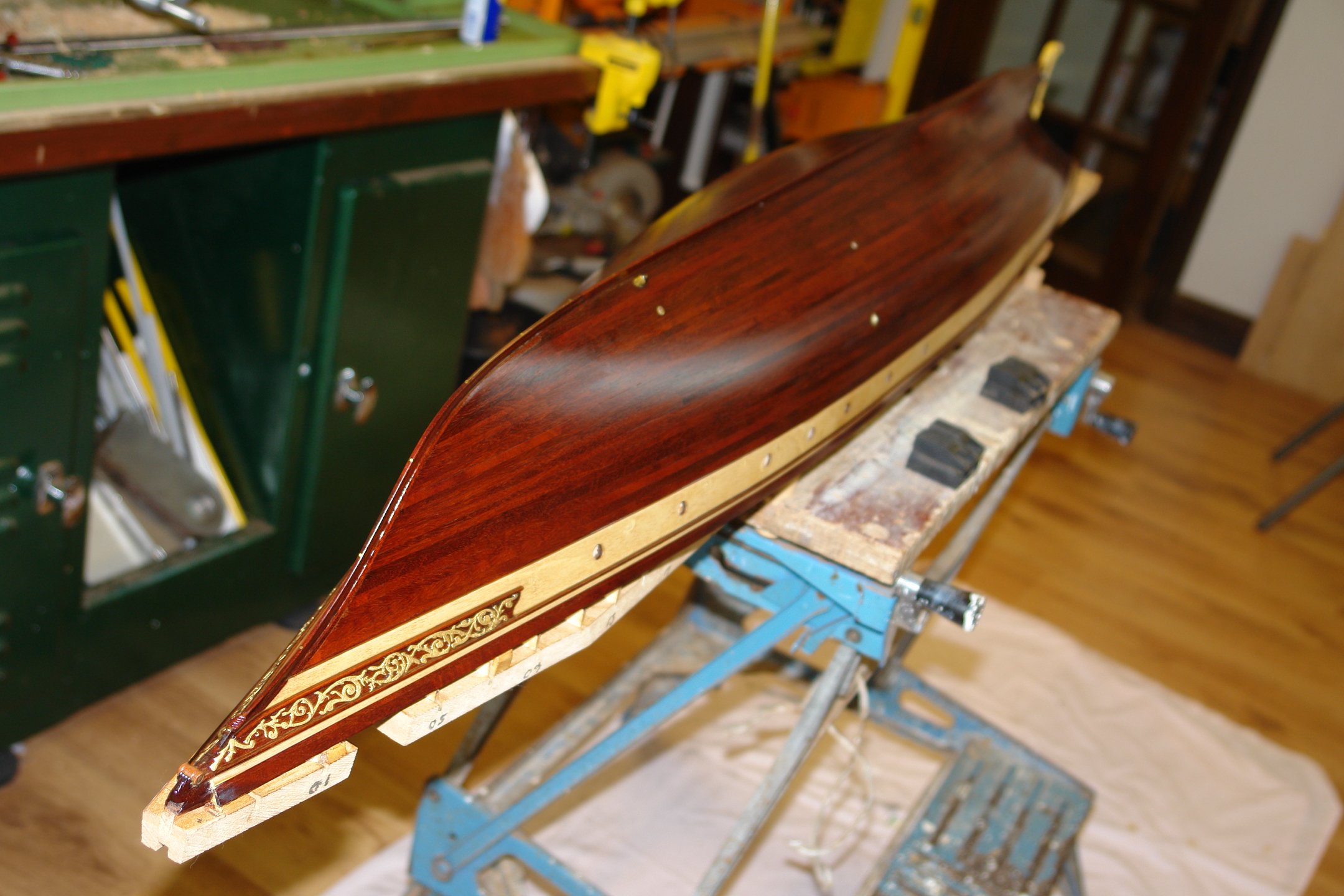
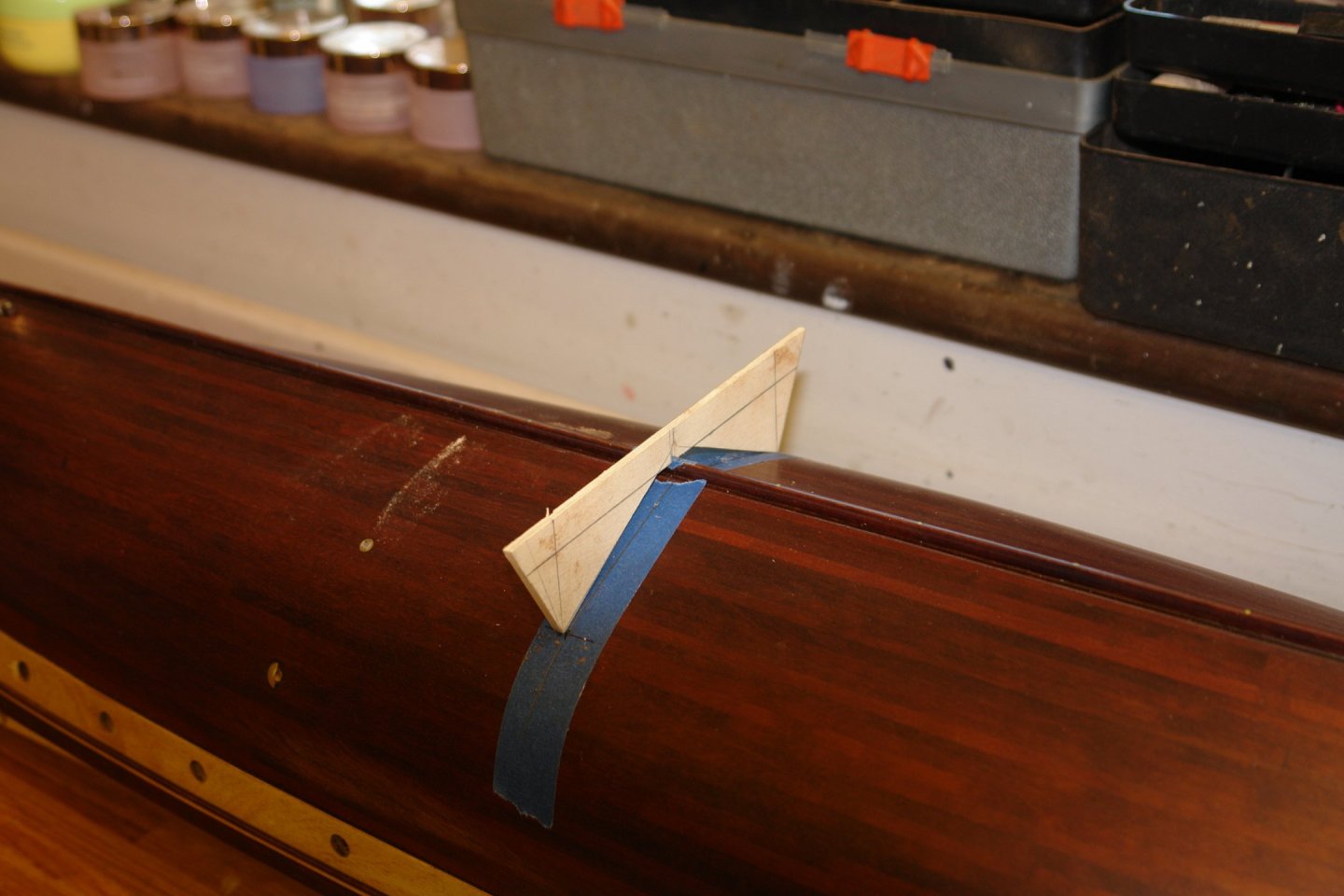
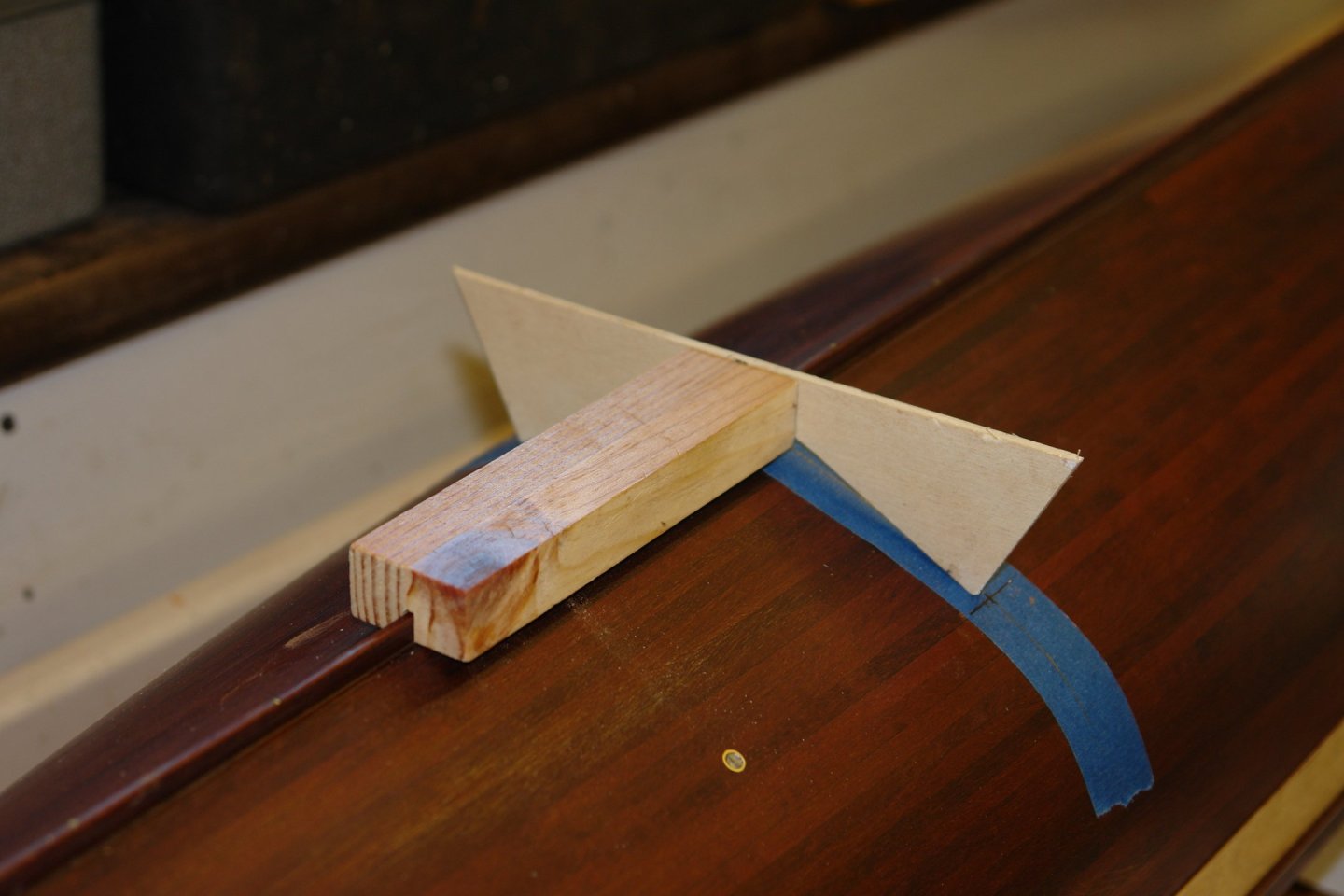
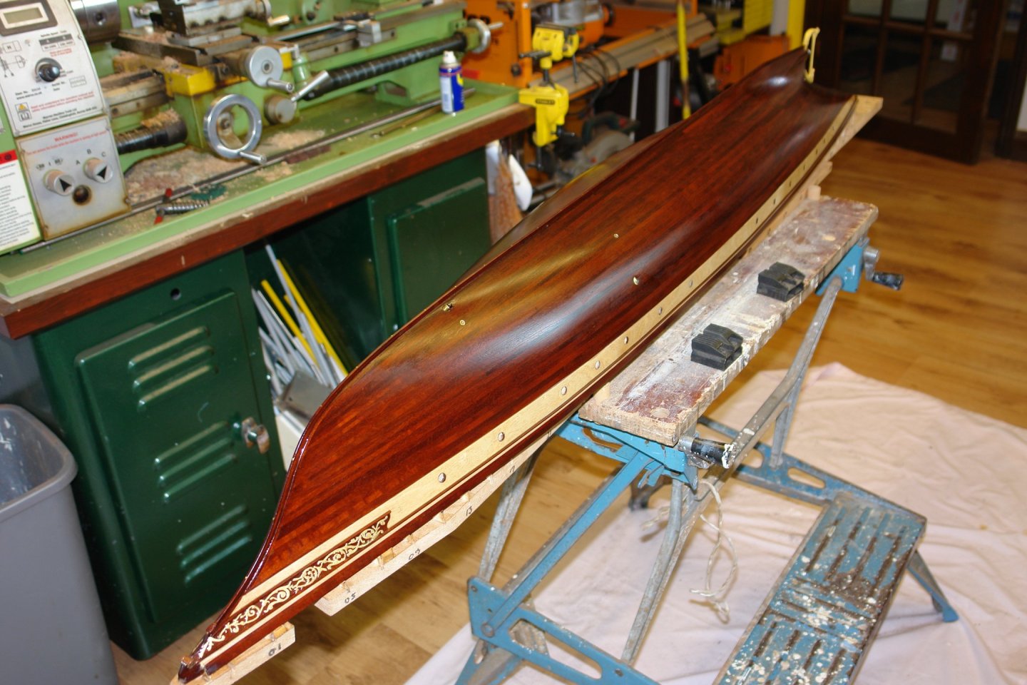
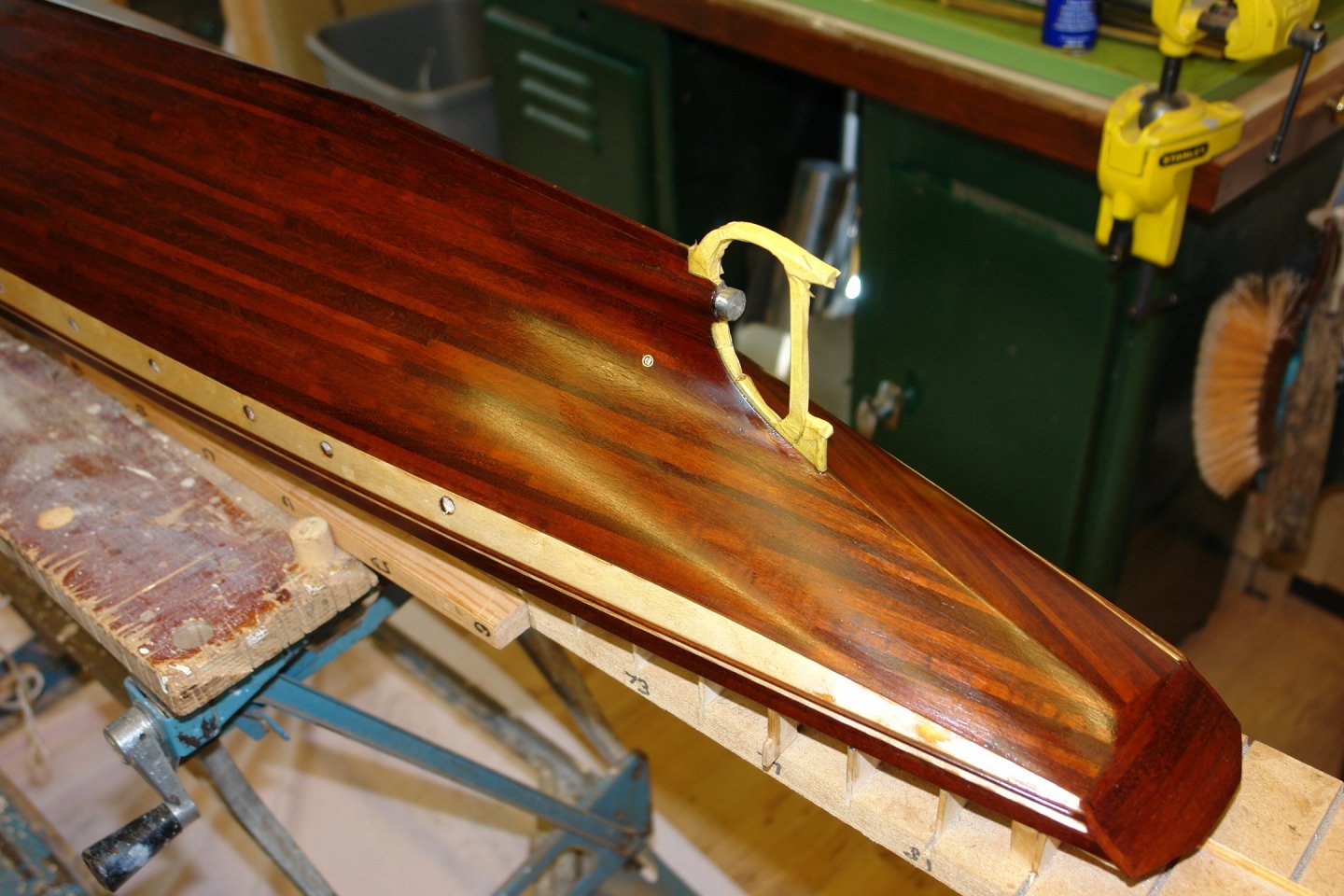
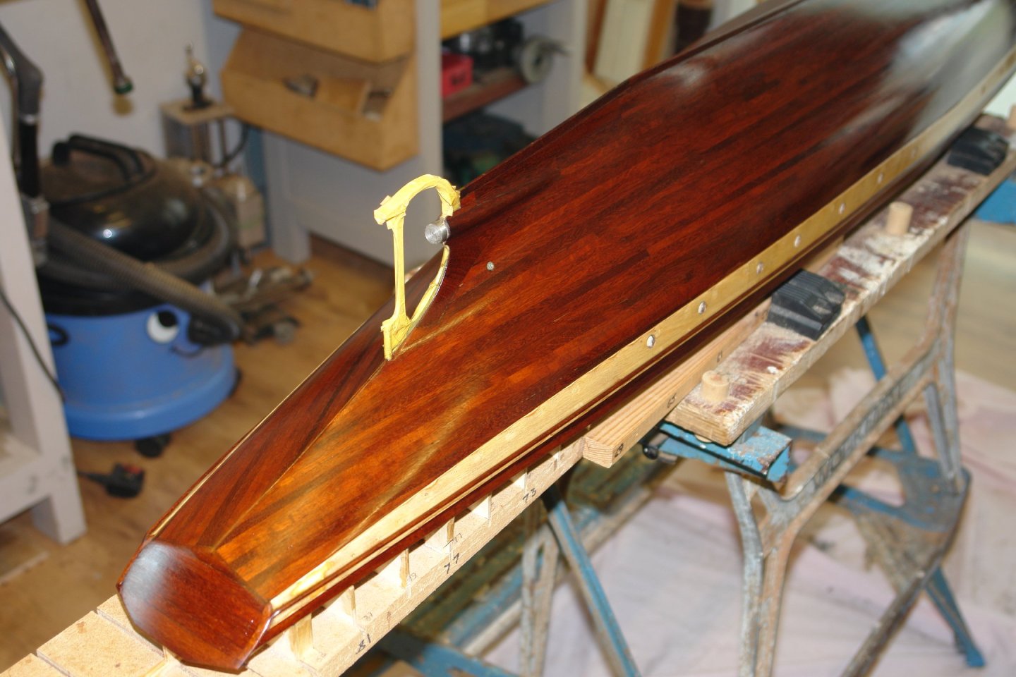
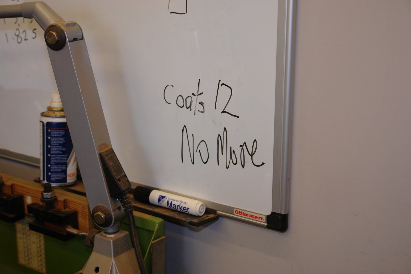
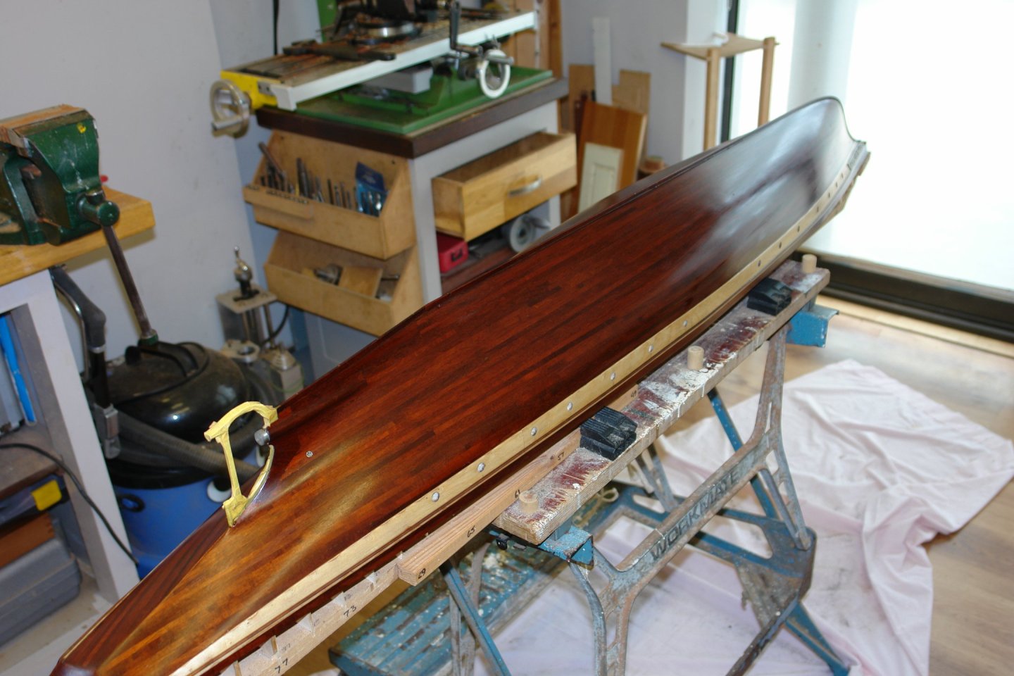
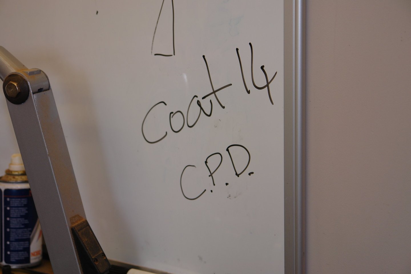
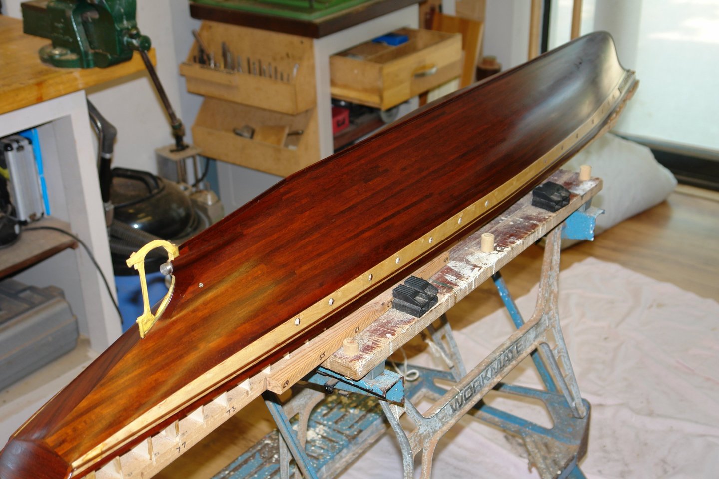
 Thank you for the feedback Eberhard, Andy, Tom, Rick and Gary. I seem to have a lot of distractions at the moment and I apologise sincerely for neglecting all your wonderful builds. This week is catch up week so be prepared. In so far as Cangarda is concerned it has been slow progress. In real life she has been shipped off to Turkey to be a part of some rich kids museum and occasional private transport / play thing. Good that she has found a new home but what a pity she had to travel so far from home to find it. The combination of other commitments, the lack of heating in the worksop together with post Christmas lethargy have all transpired to make progress rather limited. My biggest mistake has been to attempt painting the hull in deep mid winter. Each coat has been taking an age to dry. I have tried to distract myself by doing some little jobs so what follows is a combination of those plus the never ending paintwork. I decided to drill the holes to take the stabilisers. I started by making out the position with the aid of the laser level. I decided that needed a simple jig to set the angles for the drill so I created the following. It takes its location from a slot that fits over the keel. Then more coats of wipe on poly. This was coat 8. Then came coats 9 and 10. With the workshop at 5 deg C the poly was staying tacky for 3 to 4 days. Coats 11 and 12 then went on. By coat 12 I was starting to write myself messages on the white board. But then I'd find a little blemish and on would go another coat. By coat 14 I decided that I had developed a bad case of Compulsive Painting Disorder. But I then drew a line and resolved to apply no more coats. I left the hull for 5 days and then knocked back the surface with some very fine wire wool. Best regards to you all. I will be catching up with your progress over the next week.
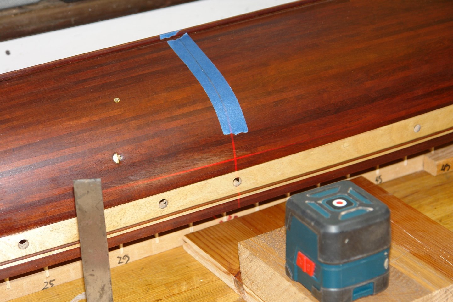


-
As ever, beautifully detailed work given the scale Roel.
- 70 replies
-
- 4
-

-

-
- Scheldt River
- Dredger
- (and 2 more)
-
Nice work Kieth. Your water level tube looks just the job.
- 732 replies
-
- 5
-
-
-
- Lula
- sternwheeler
- (and 1 more)
-
That is terrible news Brian, my heart goes out to you all.
-
Good to see we are approaching the wood cutting stage. This seems to be quite challenging but I'm sure you will pull it off.
-
George - Nice progress on Discovery and thank you for the insights into Cunard. Not as good as it once was seems to be the conclusion.
-
Smart little boat and beautifully finished. Well done.
-
Nice work on all those hull penetrations Phil. It's very nice when the junk box gives up its treasures, somehow it makes all the years of hoarding worthwhile.
- 476 replies
-
- 2
-
-
- minesweeper
- Cape
- (and 1 more)
-
Magnificent Valeriy. Happy new year, I hope 2025 brings happier times.
-
Phil, Keith, John - thank you for the feedback. One day I will have to learn to do it properly by carving.
-
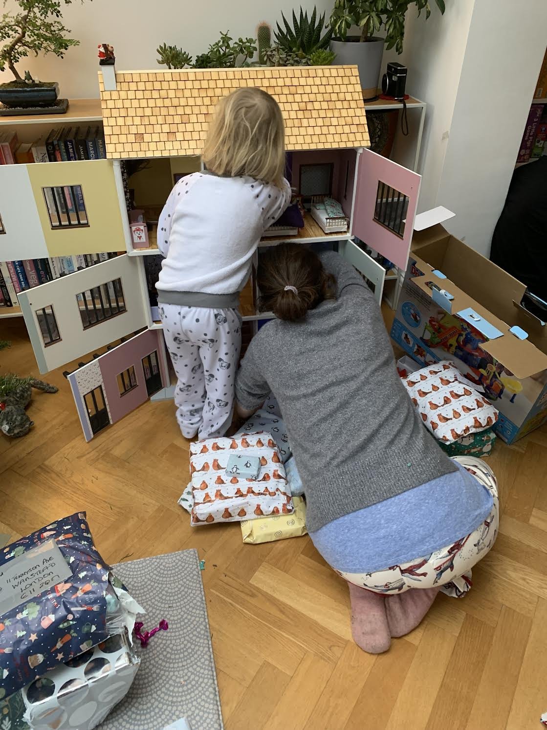
Keith - It seemed to be much enjoyed by both the Bean and her aunty "Stinkey" (my daughter). They played happily for hours.

-
I have to agree with Keith that she in now looking pretty damn good John.
-
More than one way to skin a cat. I usually follow the thin lamination method and your method had never crossed my mind but I will log it for possible future use. Thank you.
-
Excellent work Hakan. Pity about the rework but we all suffer from it.
-
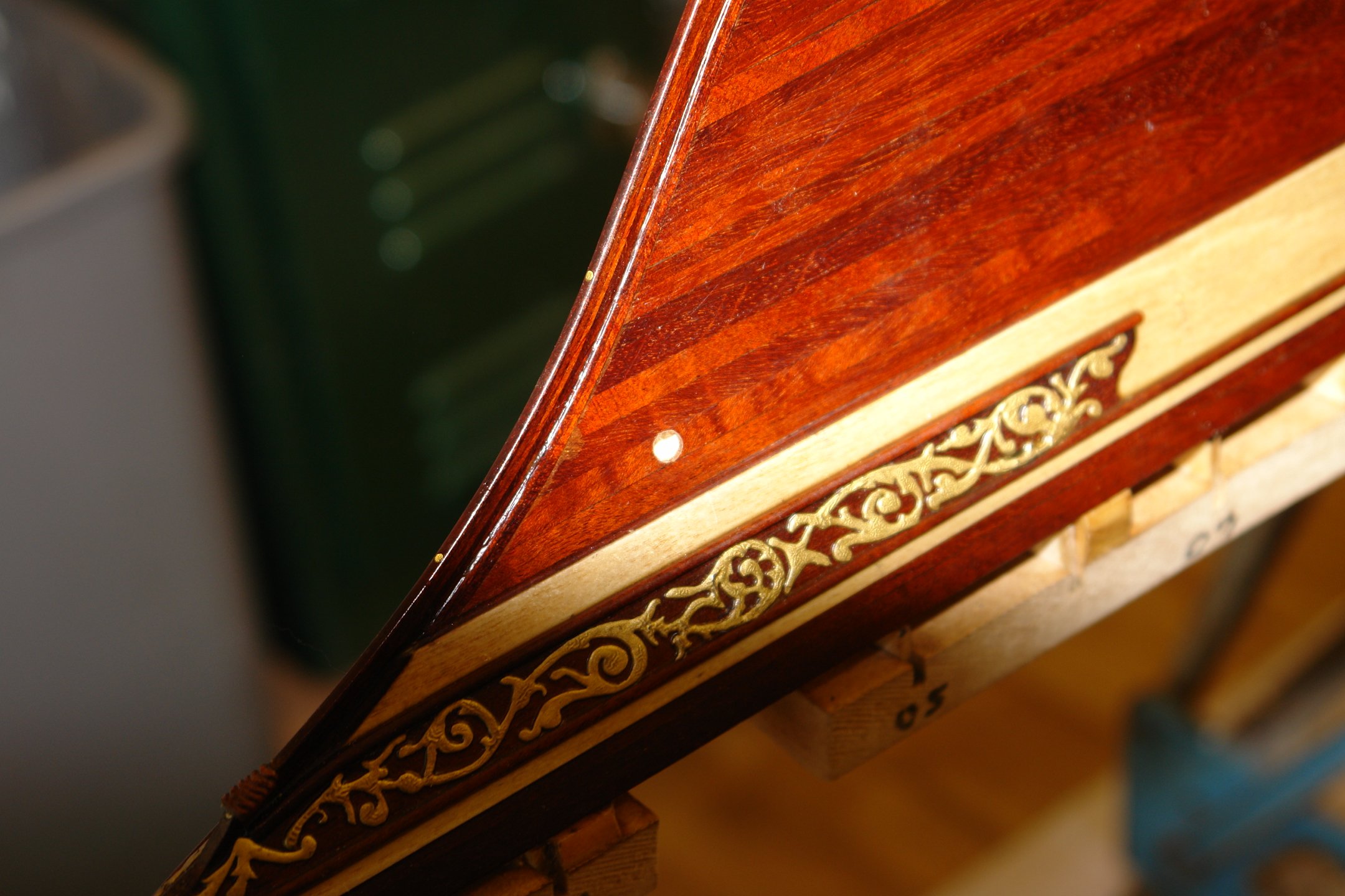
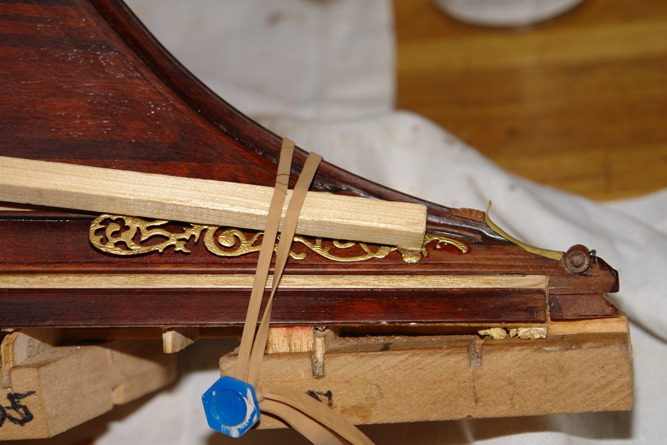
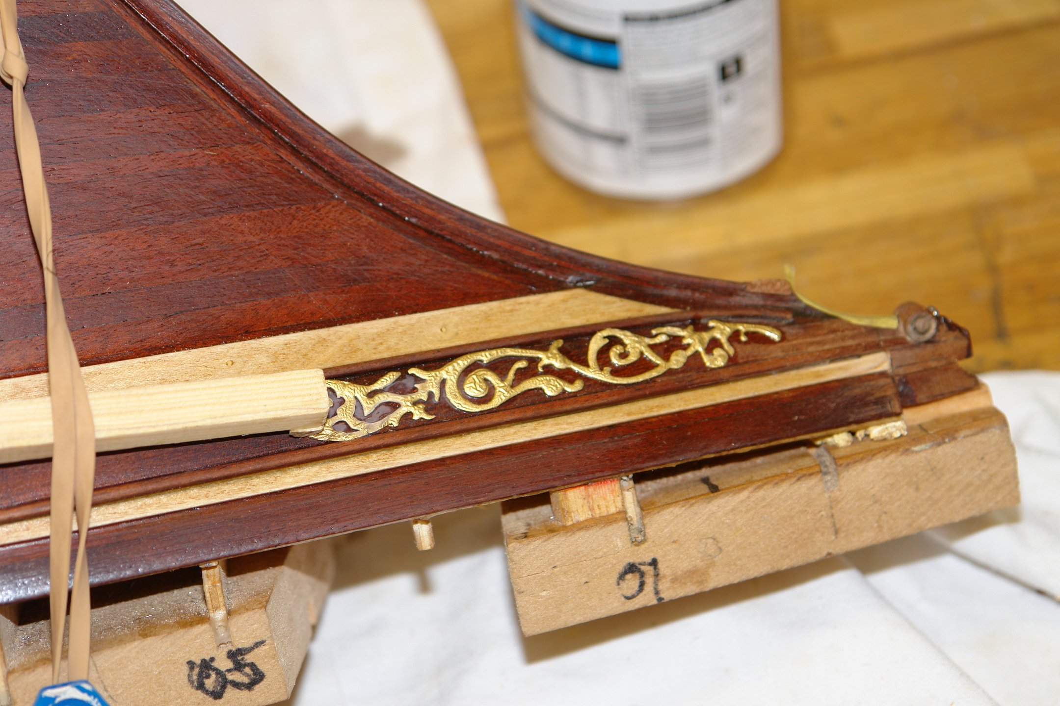
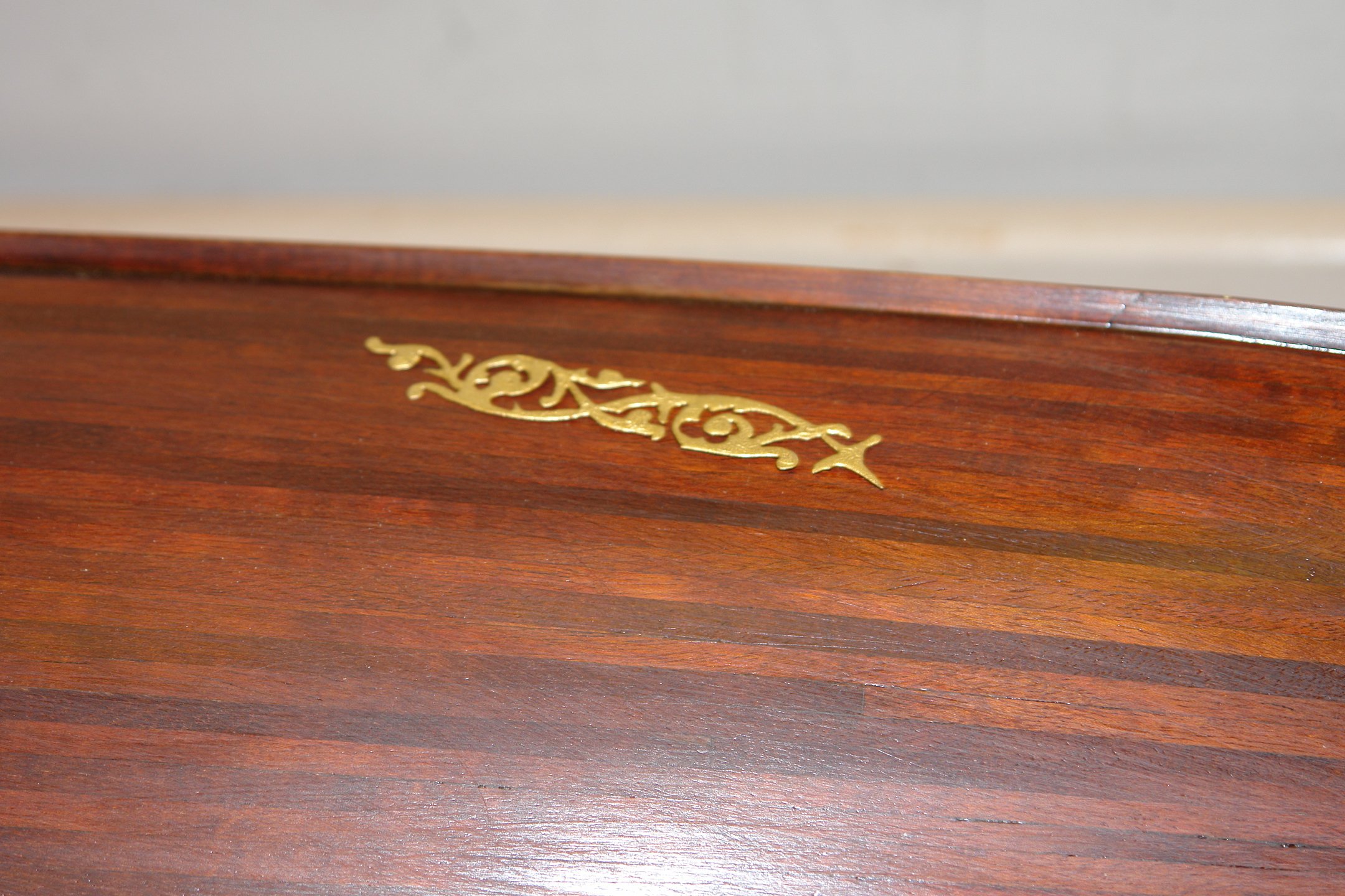
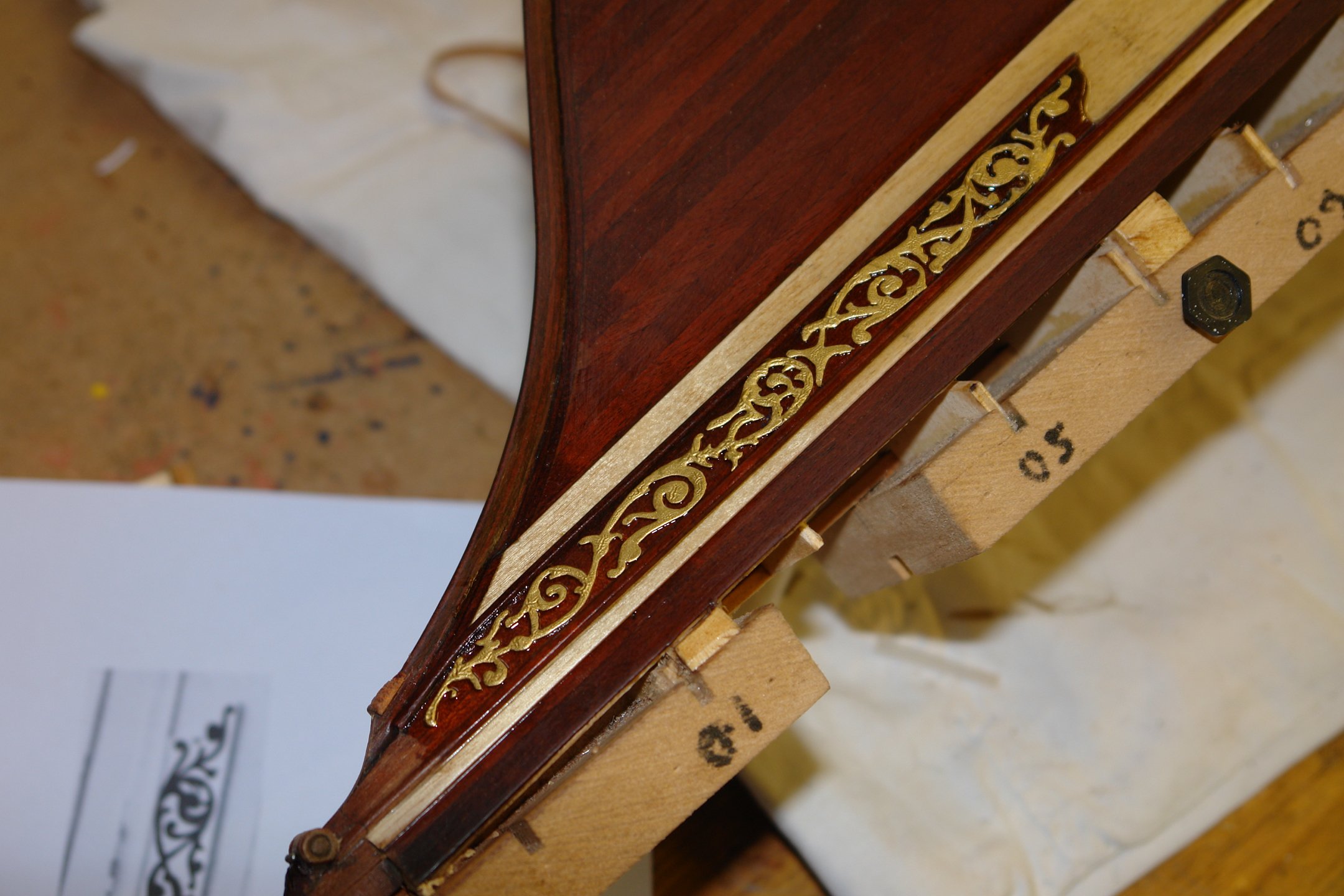
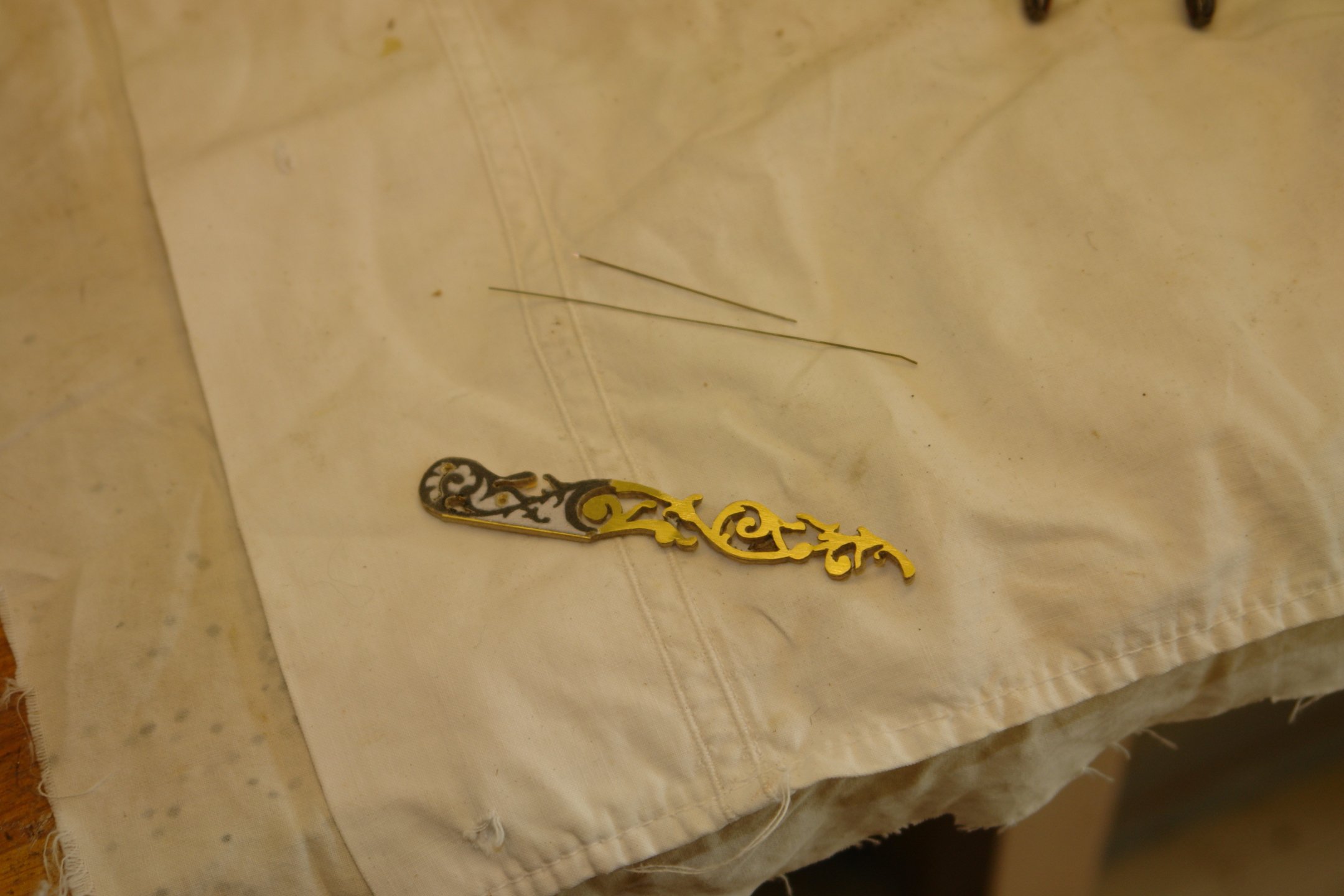
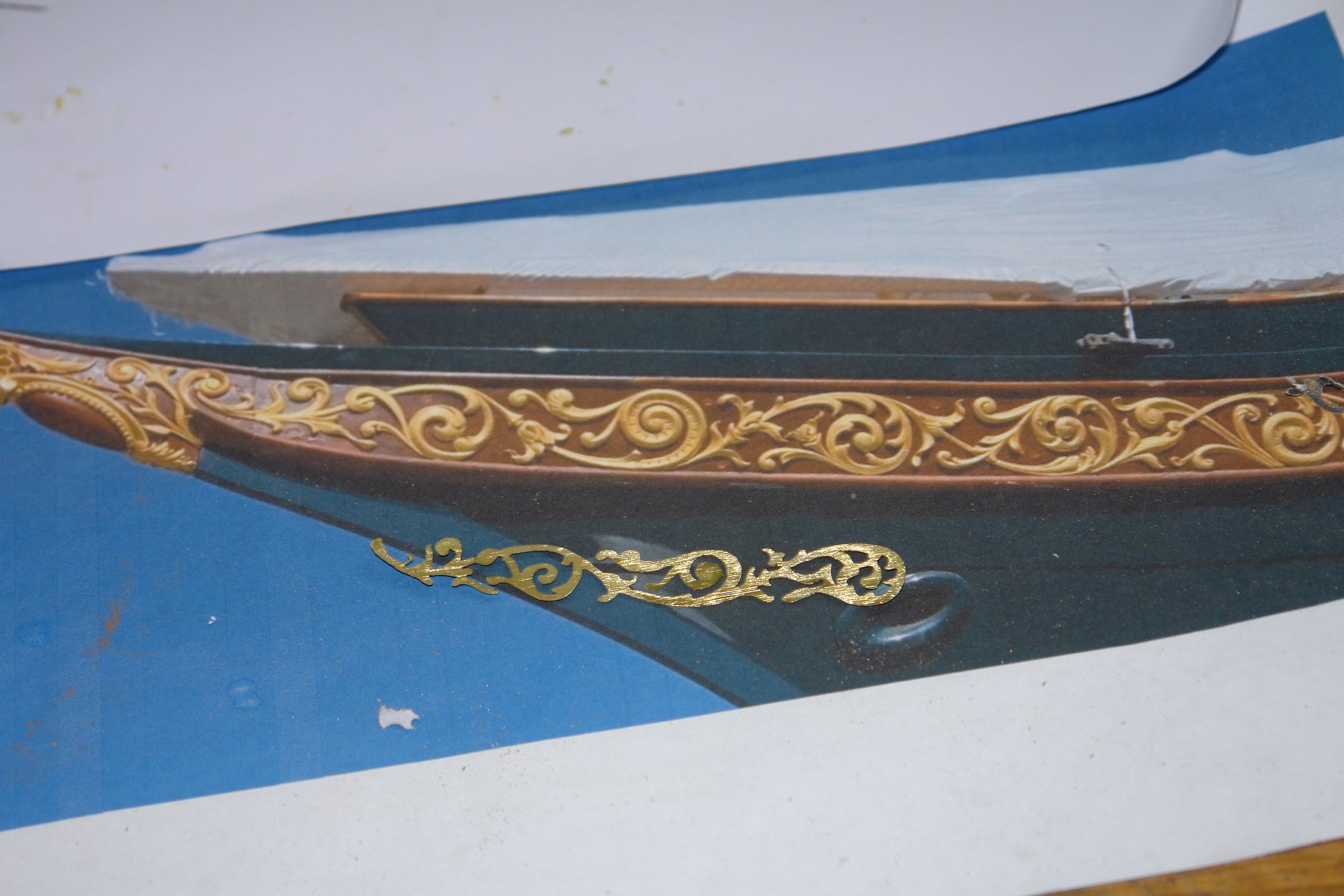
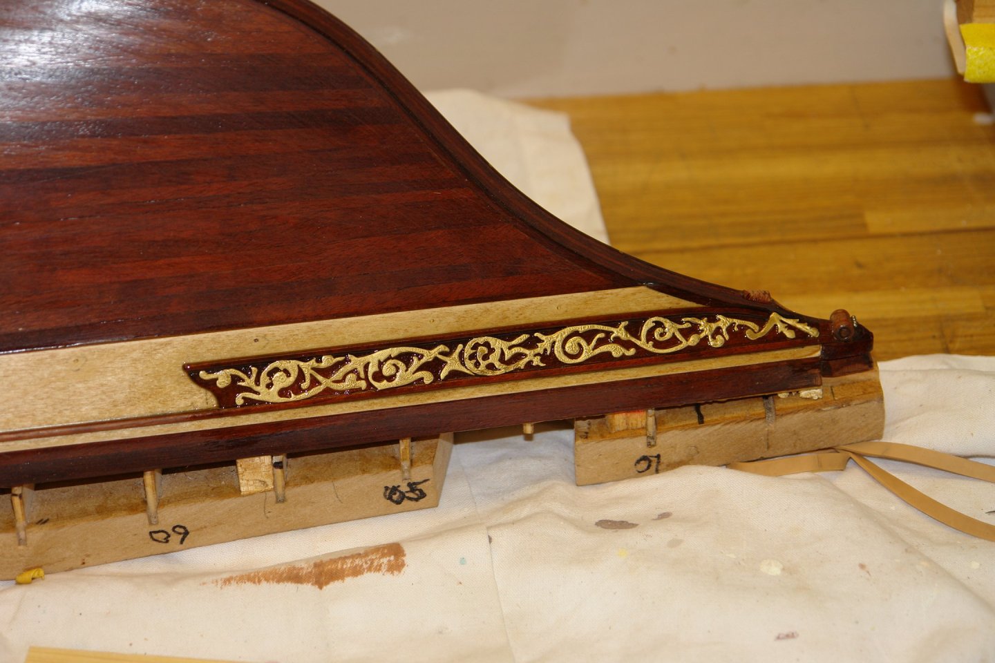
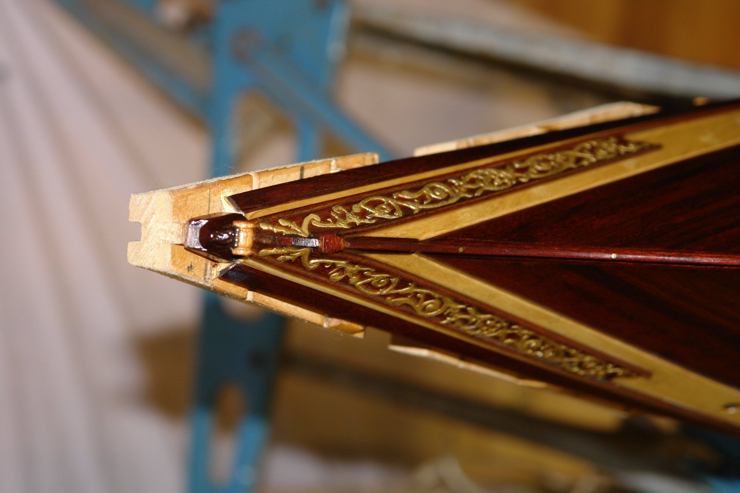
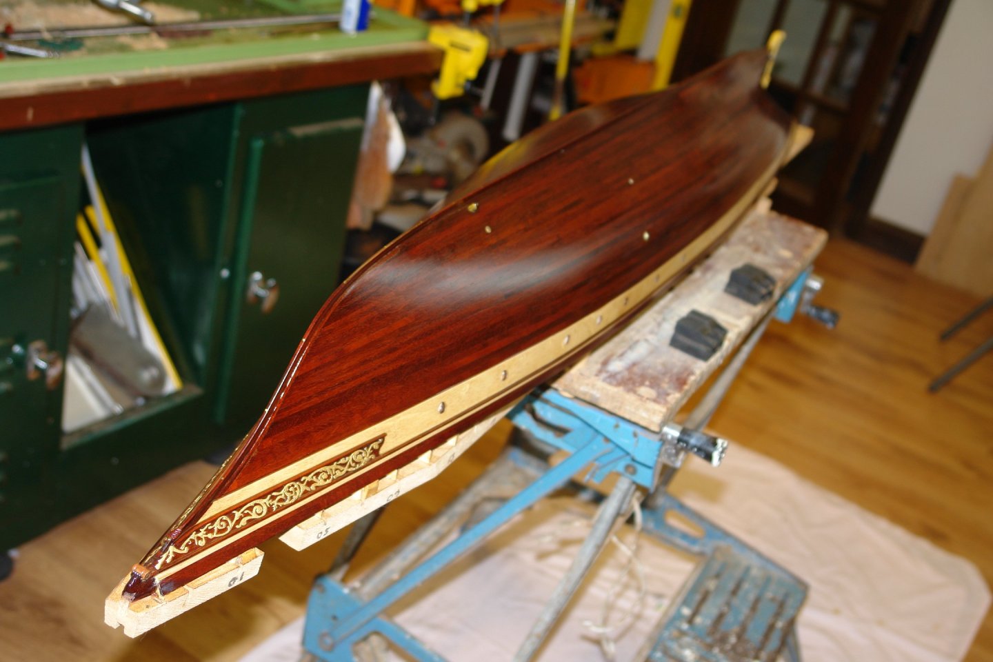
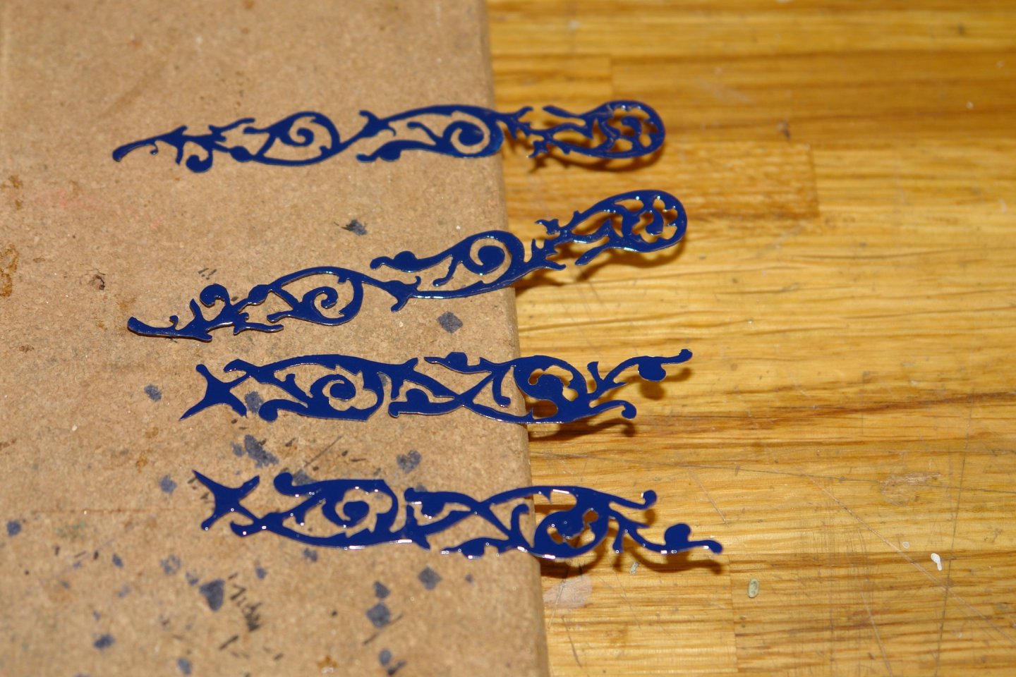
Still catching up the post with work completed pre Christmas. I finished the various bits of decoration. I put on a second coat of metal paint and left it for a couple of days before overpainting with Vallejo gold paint. The under-paint turned out to be still a bit soft when I applied the gold which fortuitously produced a textured finish which I felt was better than a smooth finish. The decoration was quite flimsy and this allowed it to be easily contoured to the hull. I held the decoration against the hull with an elastic band and a plank and then dripped CA glue into space around the decoration to permanently attach it.


-
A Happy New Year to you all.
-
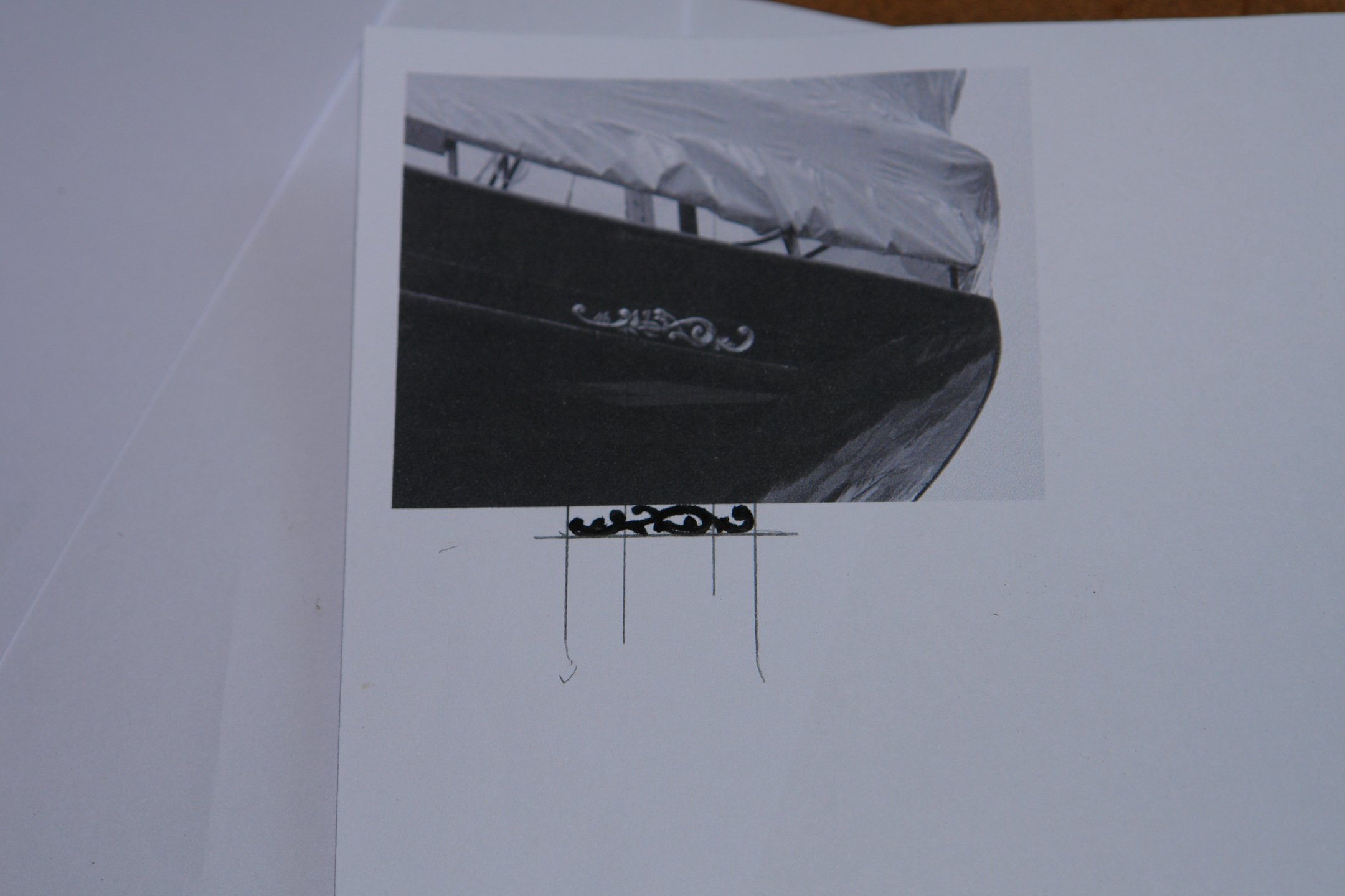
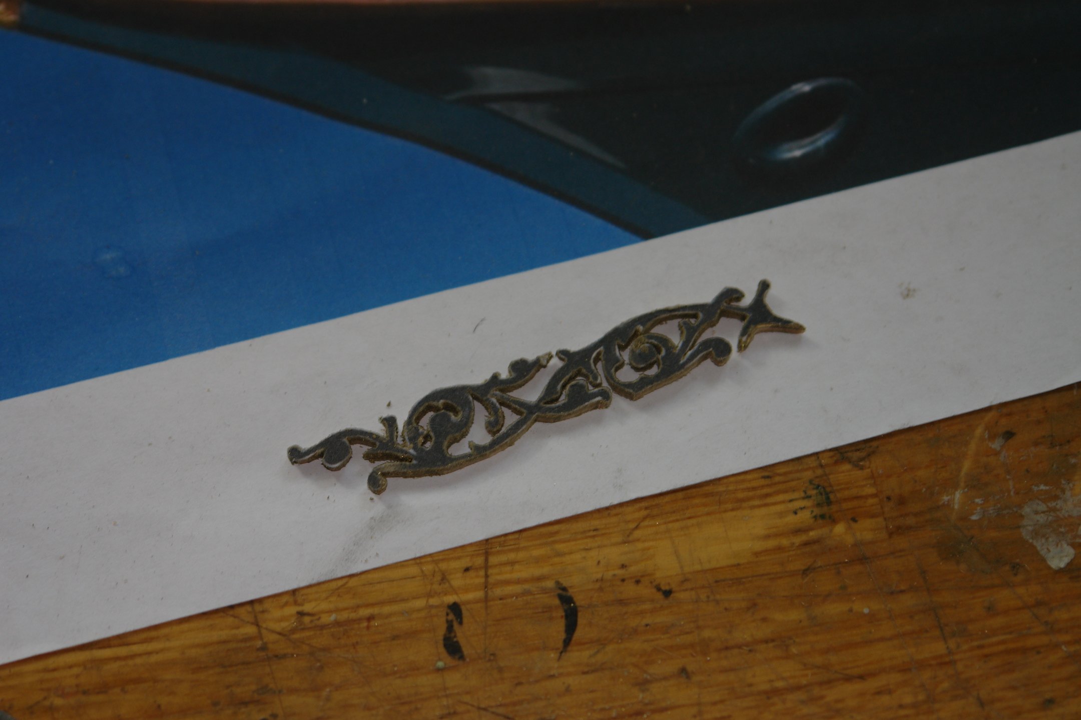
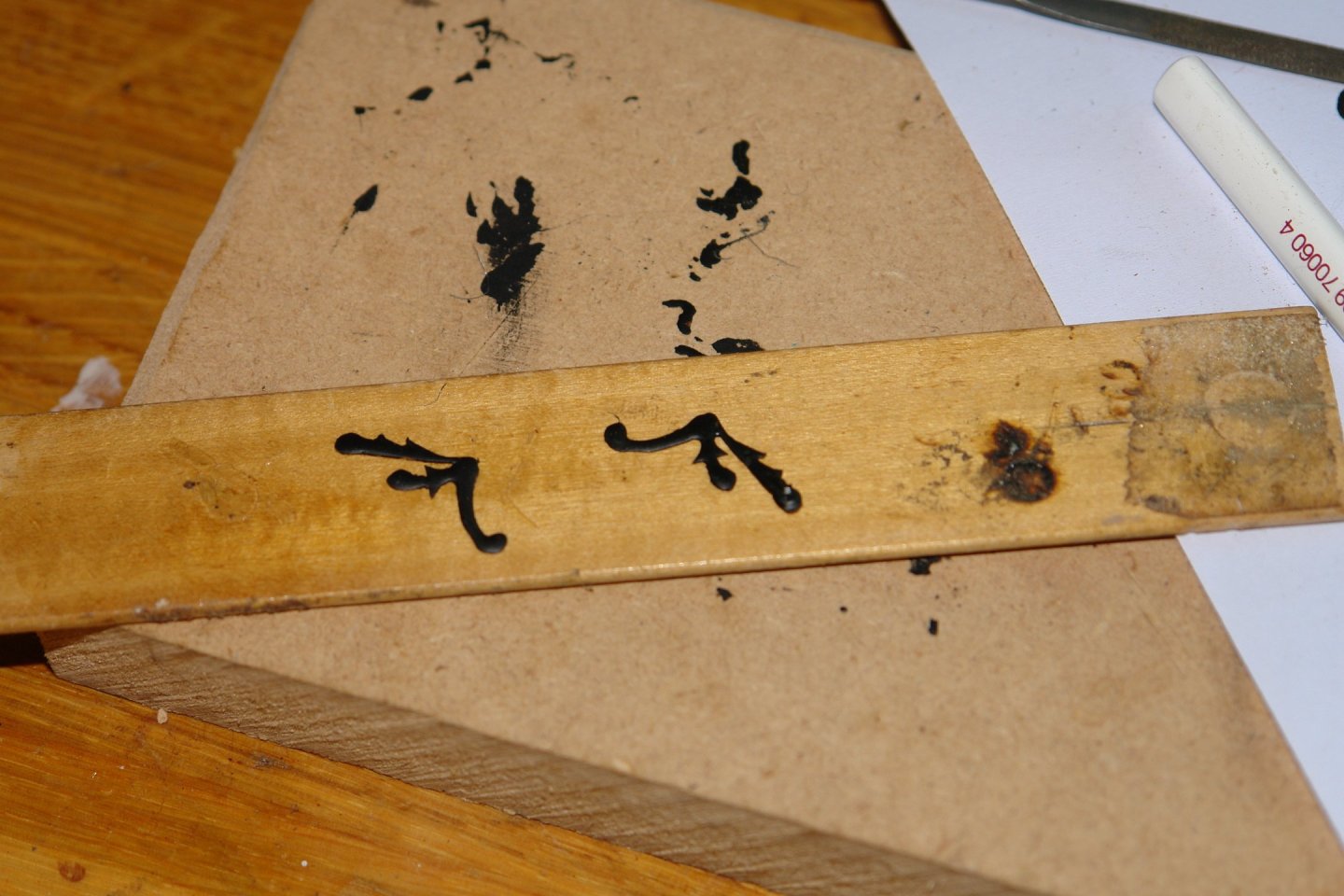
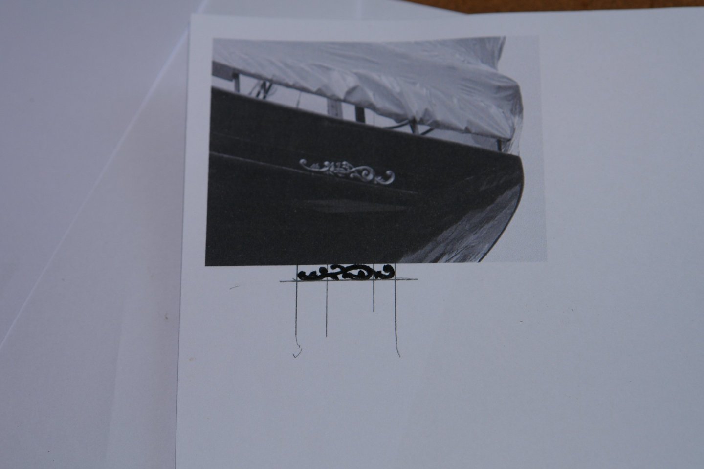
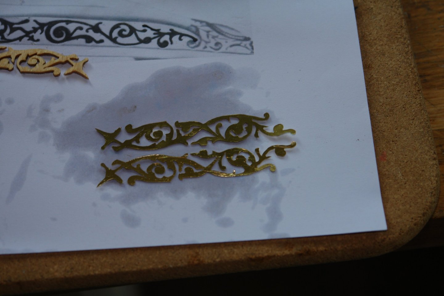
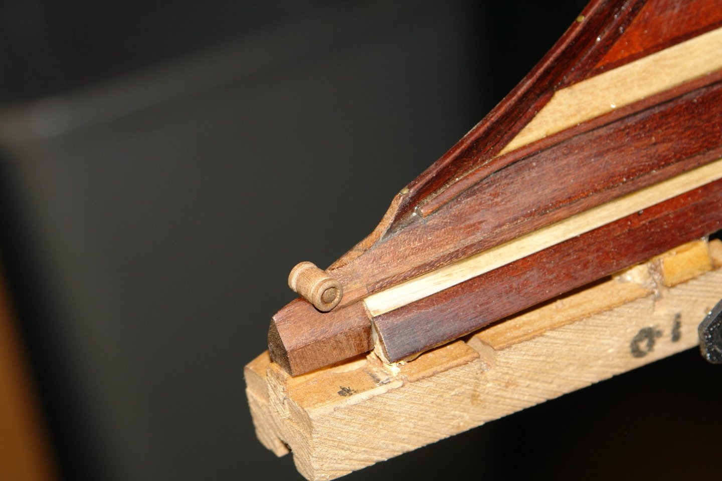
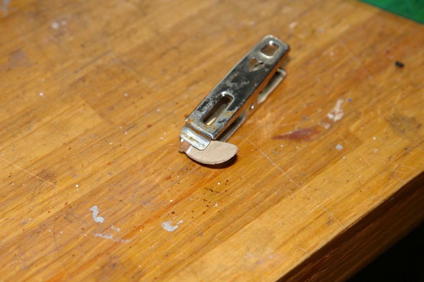
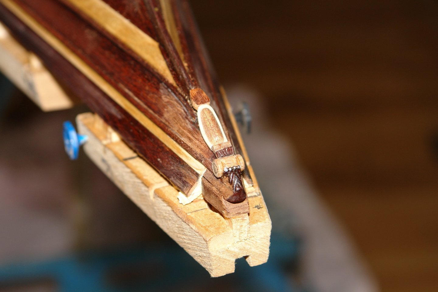
Thank you the twins! Druxey - thank you and complements of the season to you and yours. Thank you Glen - I hope you had a wonderful Christmas. Hopefully Andy. Because she is with her alternate grandparents in Lyme Regis she won't be getting it until 1st January when we go to "sit on" the Grandchildren before they return to school / nursery. Anyway back to the main event and a start on reporting the few jobs that I managed in parallel with the dolls house build. I tried both versions of your suggestions for cutting out the gingerbread. The reverse blade method worked but I found it a bit slow so I glued the 2 sheets of brass together with double sided tape and attached them to a third sheet of 1/16" plywood. This worked well. The cutting was somewhat quicker than the reverse blade method but still slow enough to provide an acceptable degree of control. "Somewhat quicker" is a relative term as it took me ages to work my way around all those nooks and crannies. The length of the decoration was circa 7" and my jewellers saw only has a 3" throat so I has to make the decoration in 3 pieces. The next photo is part way through the first piece, and features the first broken blade. And here is the first piece completed. And then the second piece - sawing completed but still mounted on the backing plywood. Then separated, using white spirit to dissolve the double sided tape. I then applied a first coat of metal paint to start building the thickness. I also started building up the prow decoration. The scroll was turned and glued in place. Next i turned the elongated "bead" before shaping it and attaching it to a piece of 1/32" ply. The next photo shows it temporarily in position with a couple of extra bits of carving also in place. The 4 beads in front of the scroll are .04" ball bearings. I have still much to do in this area to reproduce the finished article and of course much of it will be painted gold. I'll catch up a bit more before the New Year.


-
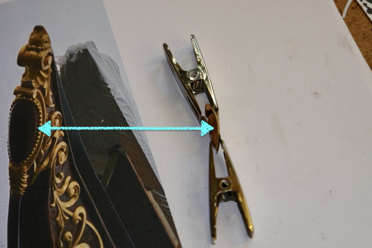
Nor are the jaws perfectly aligned, which makes them pretty useless. I have bought on line and from reputable modelling suppliers but both sources have by en large failed. I think jewellers may be a better source.
-
It happened a long time ago. The story goes - a British car manufacturers delegation went to China to do a deal but after their Chinese hosts had plied them with booze they woke up to find they had signed over the rights to the MG brand without getting anything substantial in return. MG's are quite common over here as a well specified but rather uninteresting cheap car option. They are cheap enough to sell well. Chinese cars continue to wreck the western car manufacturers!
-
Interesting Mark. I just renewed my Humbrol white so It will be interesting to see if I encounter the same problem. Hull looking very neat.
-
Ouch! I hope all is going well and that you enjoyed Christmas. The boat yard can always wait until spring.