HOLIDAY DONATION DRIVE - SUPPORT MSW - DO YOUR PART TO KEEP THIS GREAT FORUM GOING! (Only 51 donations so far out of 49,000 members - C'mon guys!)
×


KeithAug
-
Posts
3,960 -
Joined
-
Last visited
Content Type
Profiles
Forums
Gallery
Events
Everything posted by KeithAug
-
 Dan - I was pleased to find your update, you detailed explanations are always a good read. Very nice detail. I look forward to your next post.
- 238 replies
-
- 3
-

-
- leviathan
- troop ship
- (and 2 more)
-
Patrick - 2 reasons why I shy away from "working" models. Reason 1 - I imagine spending years crafting the detail to the best of my ability only for some idiot to ram it with epoxy filler reinforced monstrosity with a ram bow and oversized motor. Reason 2 - I don't like the compromises necessary to make it sail well - oversized keel and rudder.
-
Patrick - Imagination - I sould have been more explicit, it is a static display model.
-
Michael Magic- as all lanterns should be.
-
Pat. Thank you for your suggestion. I was thinking of doing something similar but using the existing frames as the former for the bulwarks. I too need to avoid the bulwarks sticking to the frames and waxing or using stick resistant paper seems a good Idea that I think I will copy. The curvature of the bulwark at the stern is quite marked and I think I will need to form it out of a number of planks cut to trapezoidal cross section - like the staves of a barrel. I would have preferred to form the bulwark out of a single piece of ply but unfortunately I don't think I have this luxury. I do like the epanding aspect of your jig - pretty neat idea.
-
Looking good.
-
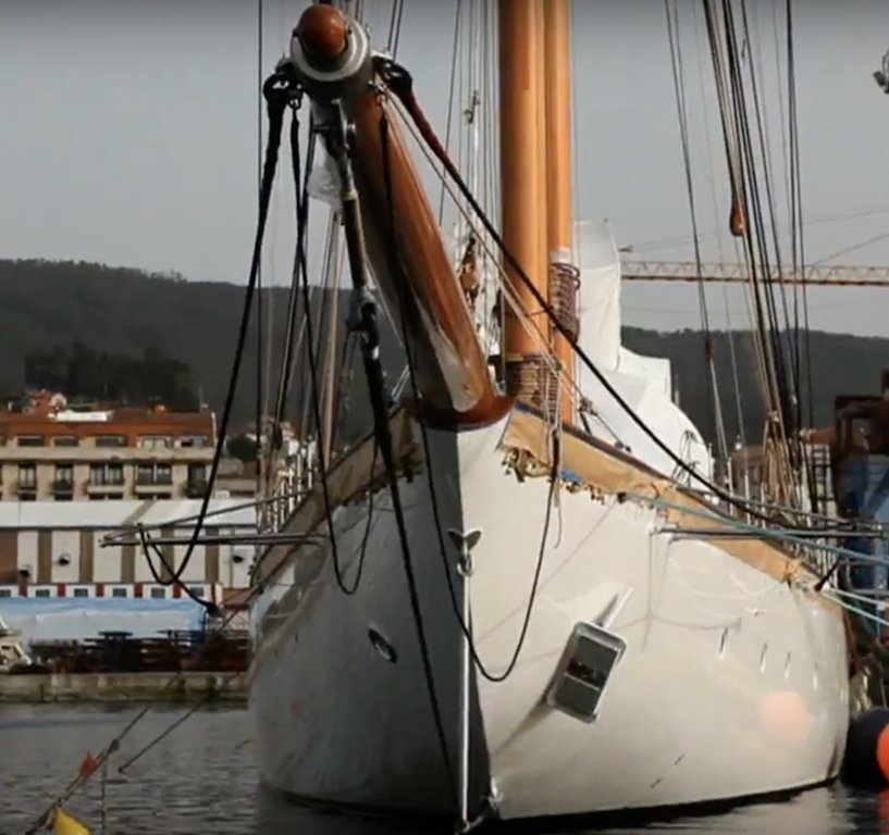
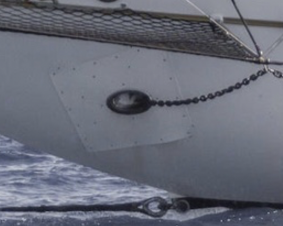
Looking ahead a dilemma presents itself, whether or not to reproduce a botched job. From photos it seems that Germania Nova was built with a choice of anchors. This isn't unusual as different anchors have different capabilities in holding on weed, mud, sand etc. The following photo shows a Danforth anchor on the port bow. I have other shots showing fishermen's anchors stowed port and starboard. Clearly the Danforth and the hull made poor bedfellows as witnessed by the following:- If i were the owner I wouldn't be very pleased!!!!!!! Must have been done by a champion bodger.
-
Michael - pretty little thing. Did you bend the top and bottom flanges before doing the vertical folds or after? Before seems to make sense but I can't see the cut marks?
-
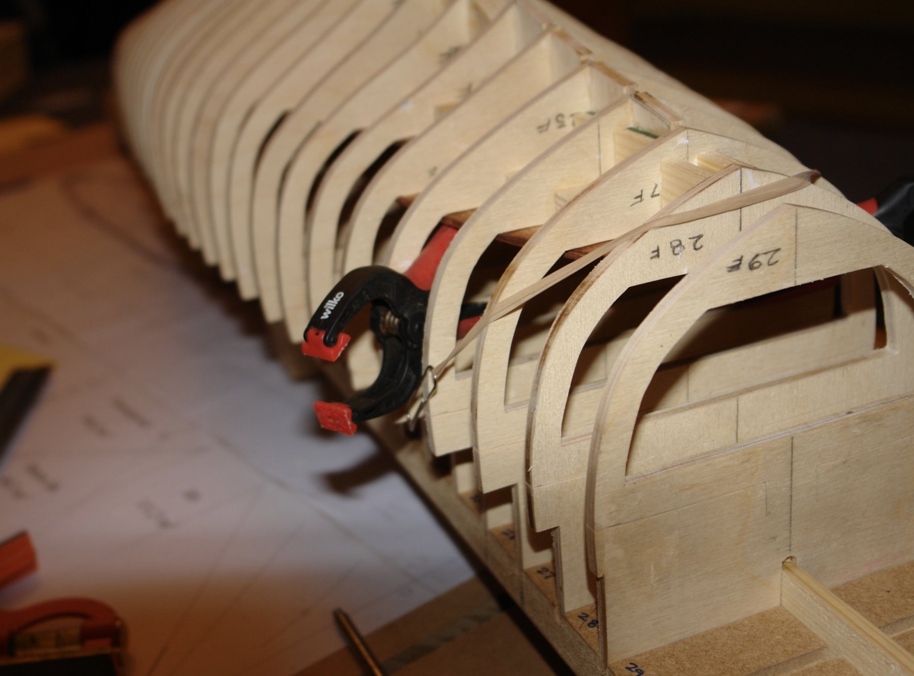
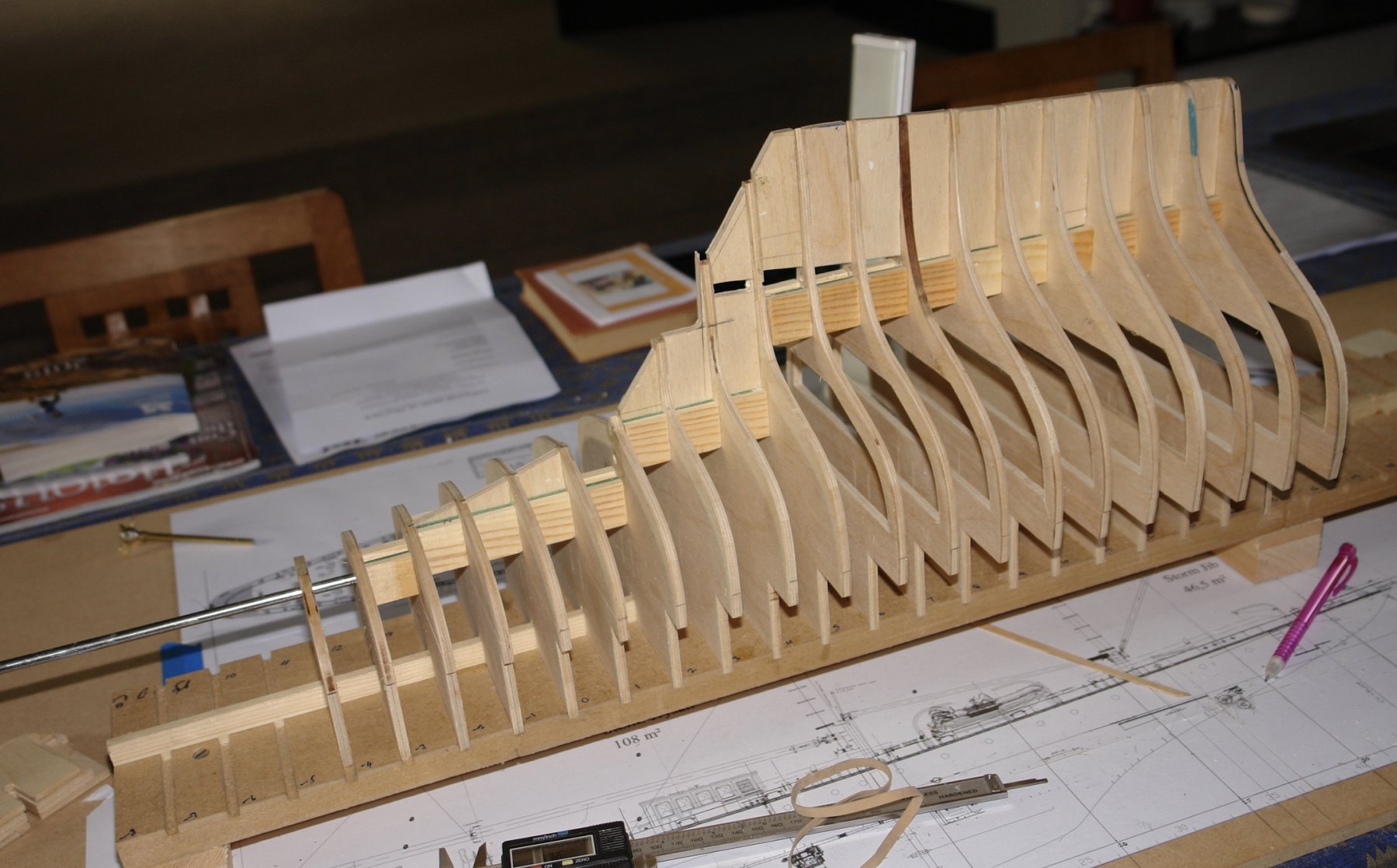
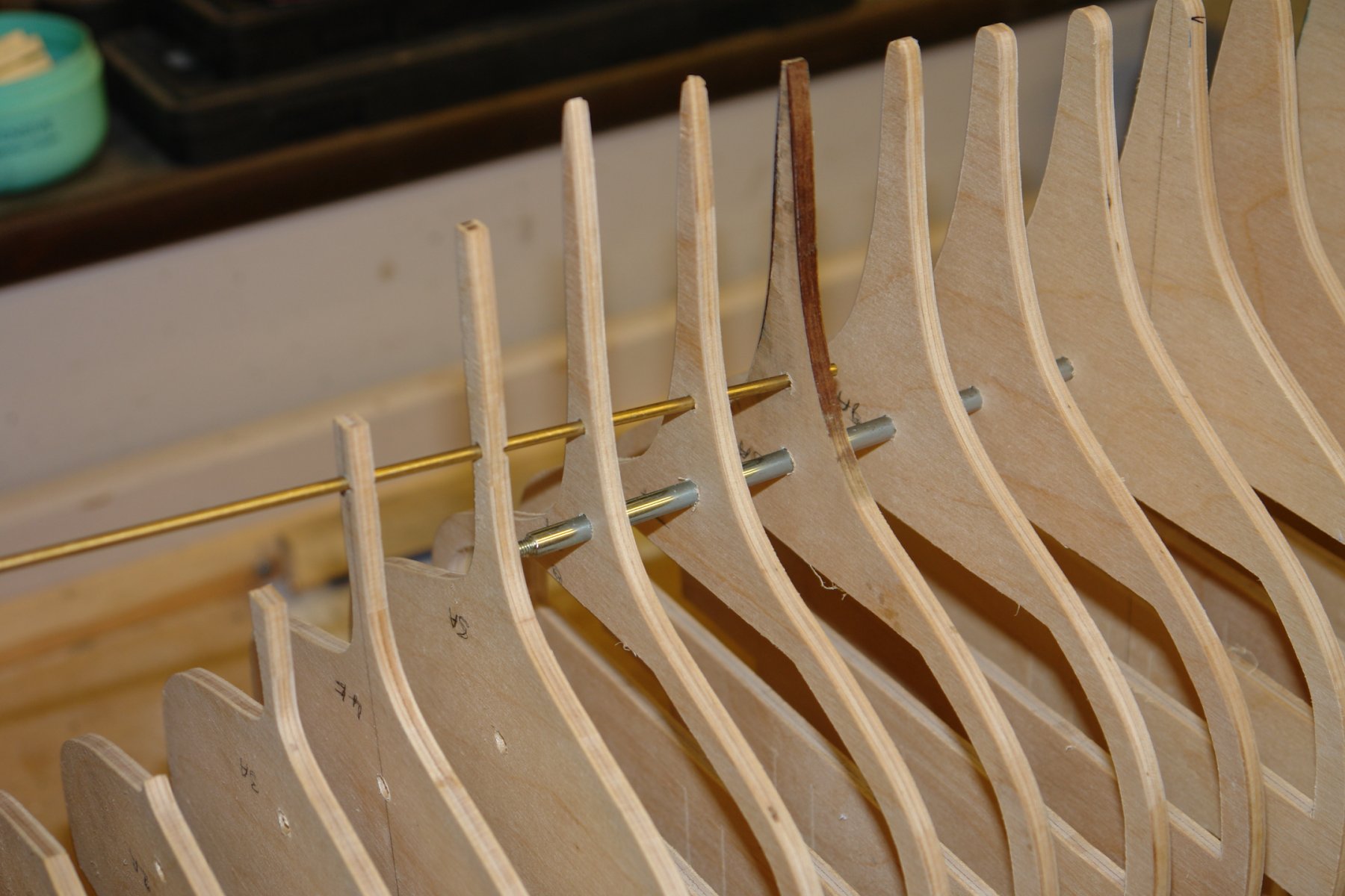
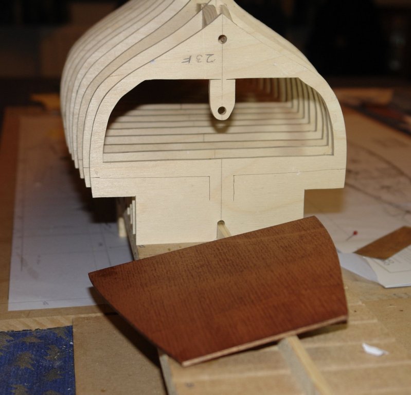
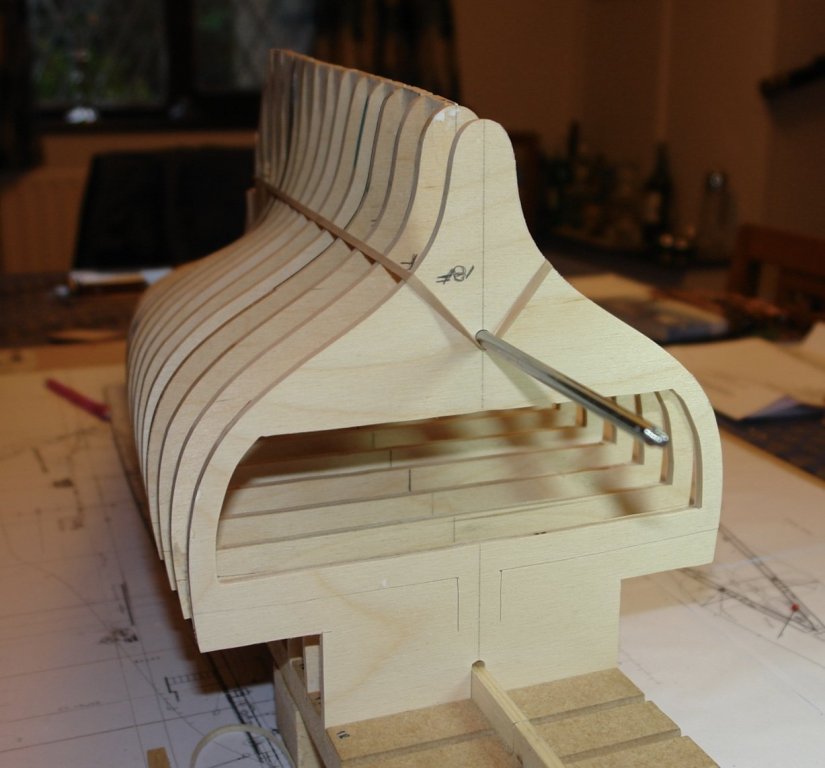
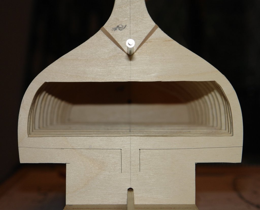
I continue to assemble the frames on the building board. By the stage in the photo below I was installing the 2nd level of cabin floor (also in the picture). By the time I got to the installation of the 3rd floor the freezer bag technique for wedging it in place had to be abandoned - the floors being quite small and not requiring the application of force over a wide area. What I needed was a "spring open" expanding clamp. I decided to use the handles of a spring closed clamp to give me the spring open function - as per next photo. I also abandoned the "V" block approach to keeping the frames square while gluing. I decided it was much easier to use the adjustable square with the frame held against it by the rare earth bar magnets - next photo. I have now finished assembly of the frames, spine and keel pieces and just have to attach the stern and bow formers before I start fairing.


-
Michael - are you putting a light source in it?
-
Thank you for taking the trouble to explain, it is much appreciated. I am sure I will borrow some of your techniques. Kindest regards.
-
Wefalck, Michael, Dan, Paul. Thank you - glad you liked my improvisation - it's all part of the fun. Paul - I have watched with sympathy your garage thermal challenges. It was a pleasant 13 deg here today - a reminder that spring will soon be here.
-
Unfortunately "Old Father Time".
-
Jealous - i want to have a go at that light.........and those rails.....
-
Druxey I knew about these. But I didn't have one. I thought however it was the sort of thing I needed. I then thought I could make it with a balloon. But we didn't have one. So then I thought of the freezer bag and a straw. very cheap and quick.

-
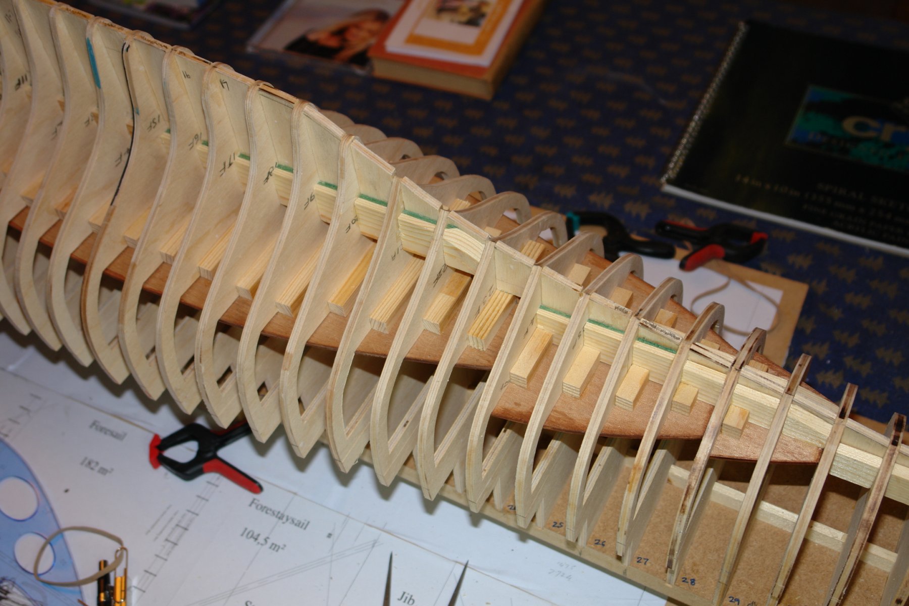
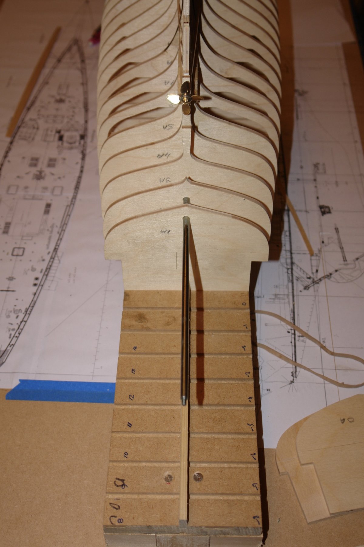
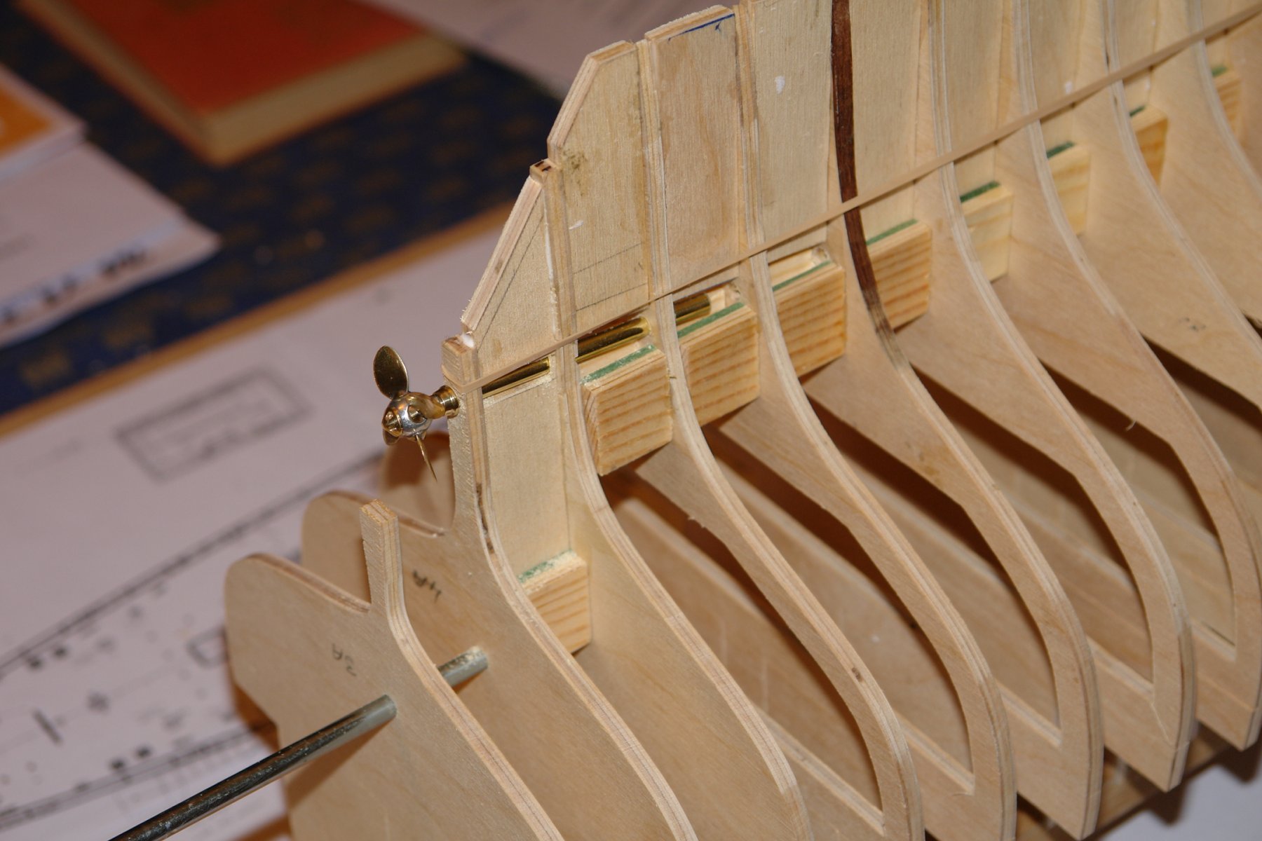
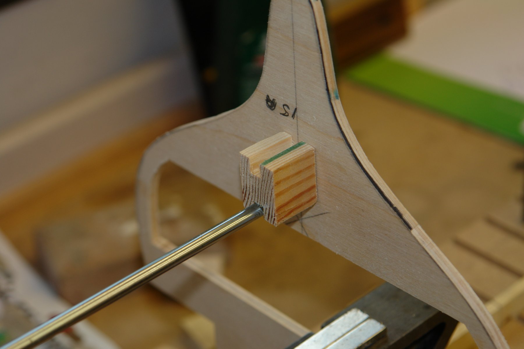
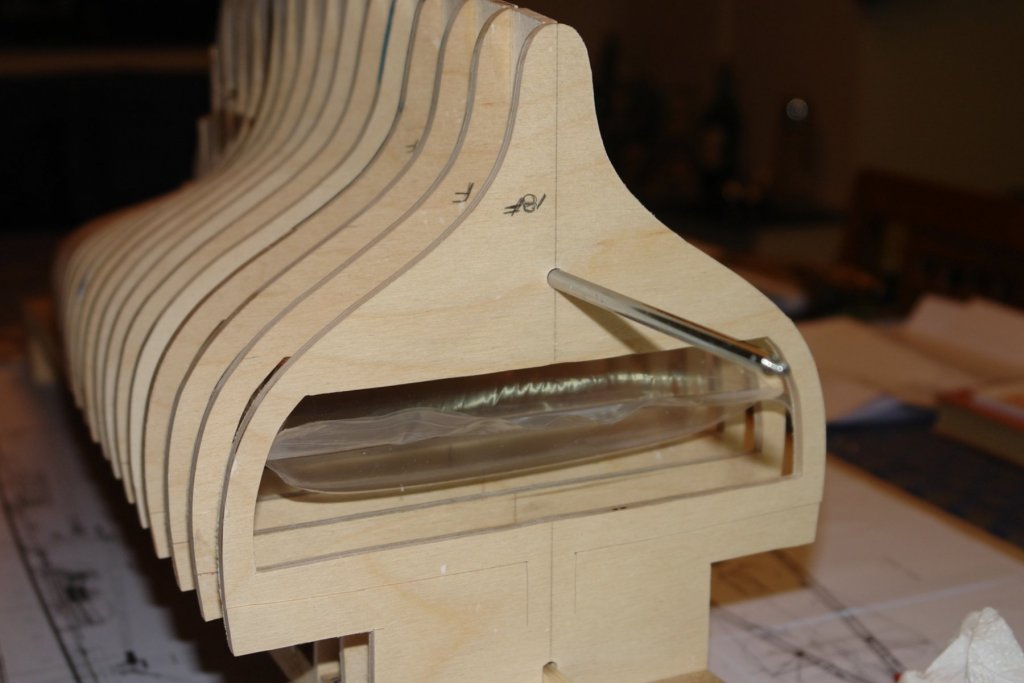
The build is being allowed to proceed on the dining room table but full access must be given at short notice. I started in the middle and worked towards the stern. The alignment rod system is working well and has the added benefit of forming a nice peg against which to locate the elastic band that is being used to clamp the frames while the glue on the "H" spacers and the keel pieces dries. I am sighting the alignment rods against the up-stand in the baseboard as further check on axial alignment. The keel webs are aligning well and I am not regretting the lack of a continuous keel piece. I also took the opportunity to open out the prop shaft pilot holes and test fit the prop. I needed to install the first of the cabin deck floors. I previously said there are 3 cabin deck levels, this is because I forgot how to count, there are actually 4. I cut out the floor from a sheet of 1/8" mahogany veneered ply using the dimensions in the previously posted data sheet. The floor had to be installed inverted and needed to be held firmly in place while glued. It was preferable to hold the floor in place over its entire surface rather than relying on discrete pressure points. I did consider cutting opposing wedges as an option for clamping the floor in place but in the end I made the job easier with the aid of a zip seal freezer bag and a drinking straw. The deck was inserted and then the freezer bag was partially inflated (using the straw) sealed and inserted above the floor (under in the inverted hull). I purposely overfilled it so that at first it would only partially insert. I then bled a bit of air out and tried again. After a couple of tries It went fully in creating a very snug fit. The position of the cabin floor was then adjusted until it was in the correct position. The clamping pressure was quite high and it took a bit of force to adjust the floor position. I then cut a series of braces and glued them to the frames and floor to hold it in place.


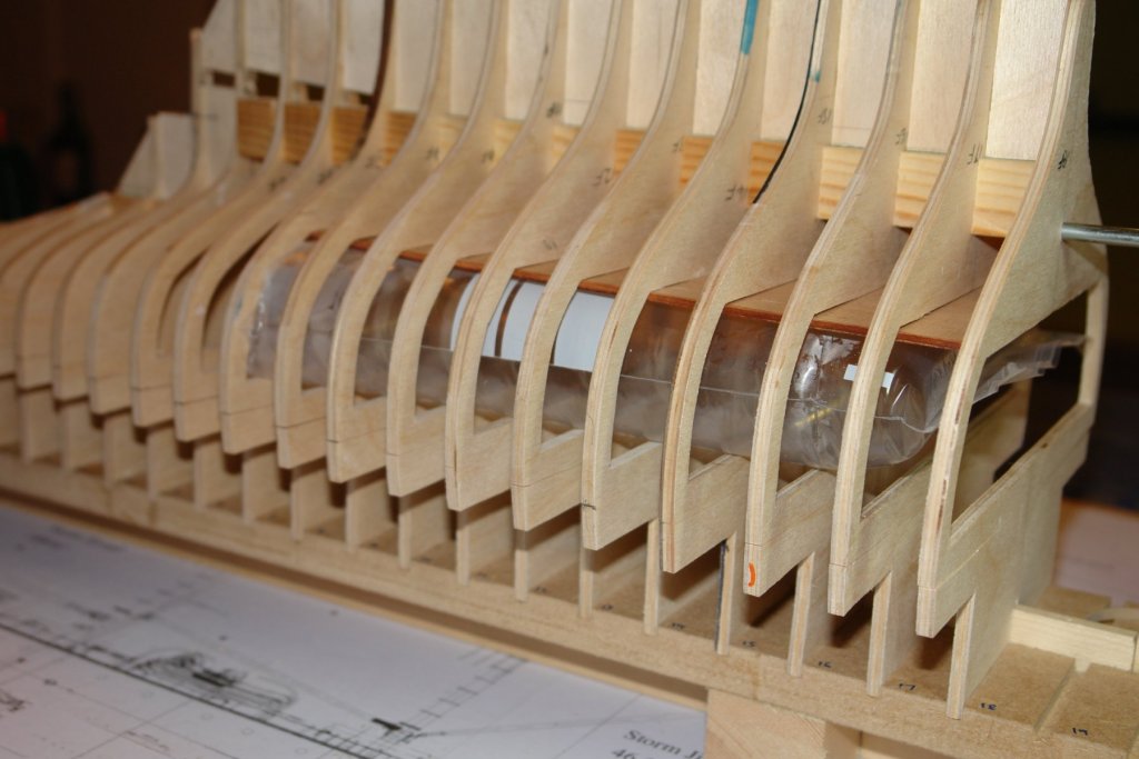

-
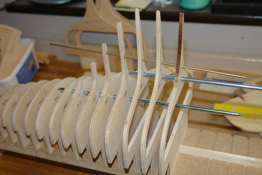
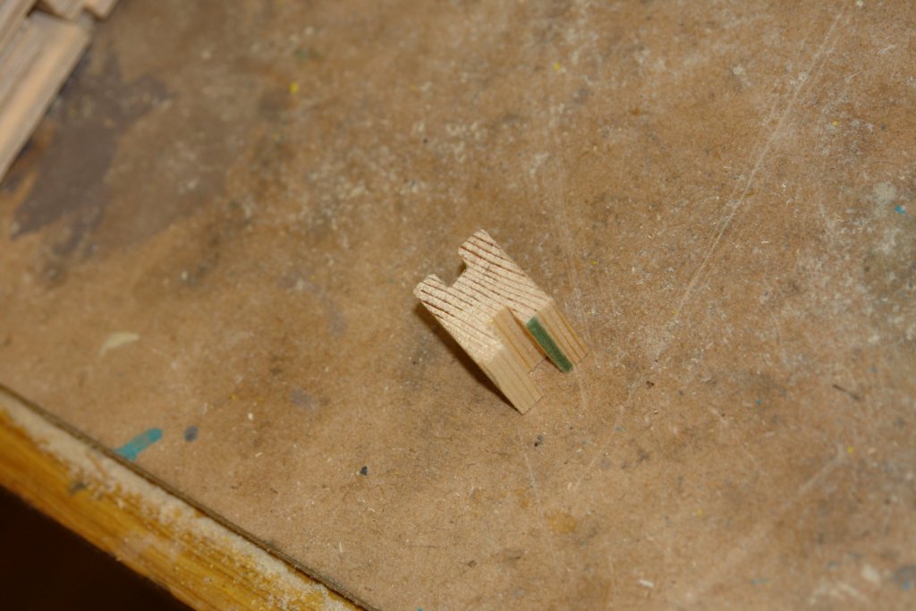
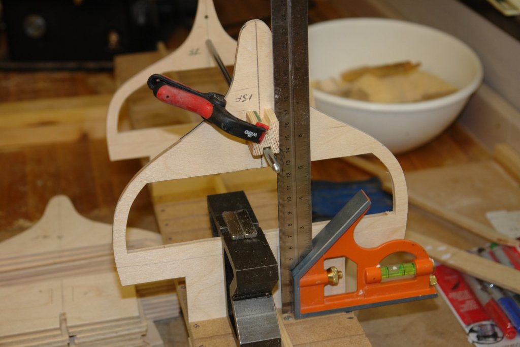
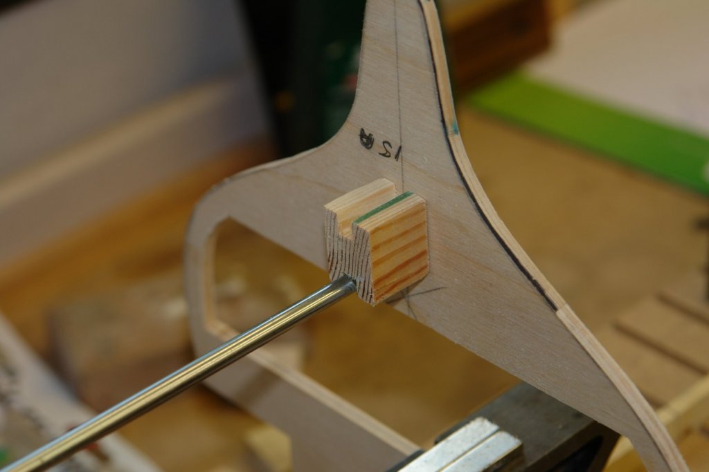
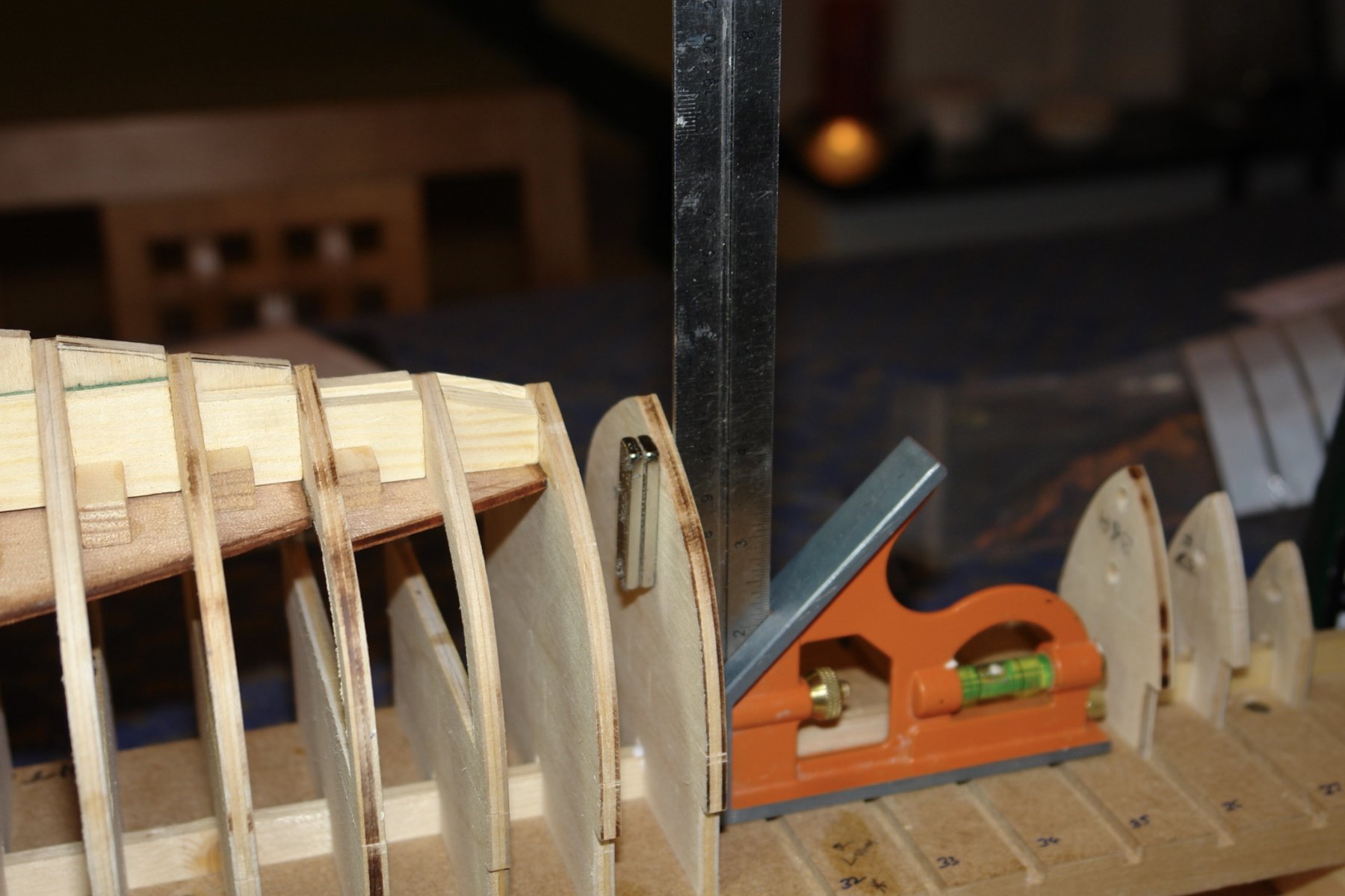
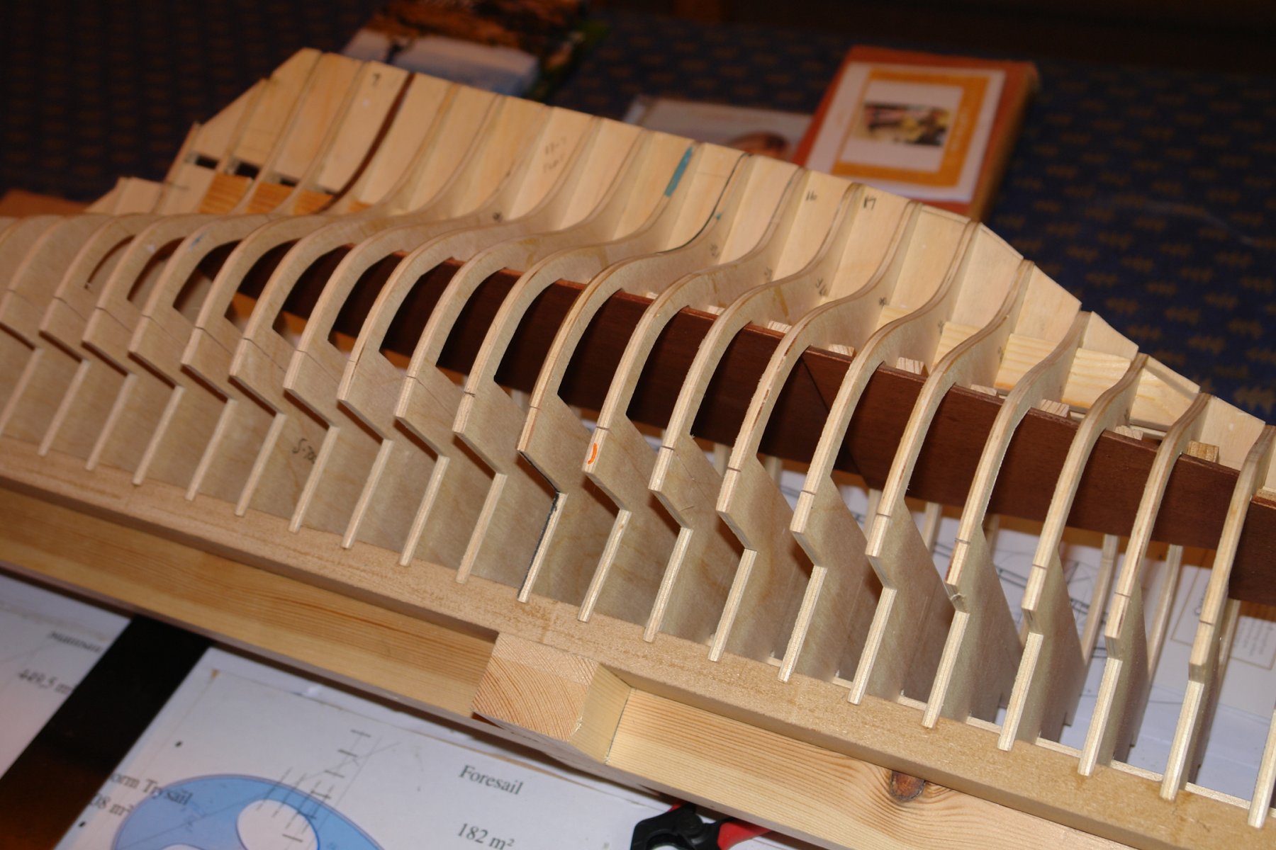
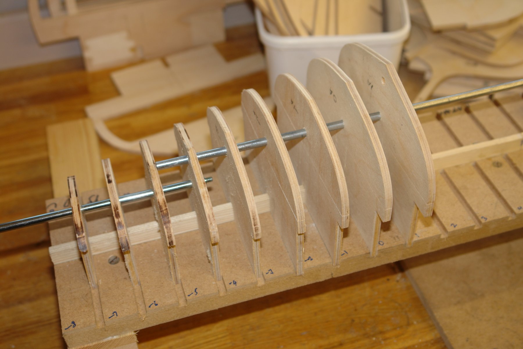
Today I did some more detail alignment checks before commencing glueing the frames to the building board. I placed a number of frames on board and pressed them down firmly before checking alignment with the 6mm diameter steel rods. While I was at it I checked the alignment of the prop shaft pilot holes (the brass rod below). The conventional way of joining the frames would have been to create a continuous keel (as I had previously done on my Altair build). This would have involved cutting a vertical slot at the bottom of the frames (top in picture). The problem with this approach on Germania is that the frames towards the rear of the fin are very narrow, so narrow in fact that the creation of the slot would have destroyed part of the frame profile. I don't want to lose the profile so I am taking an alternative approach. This involves creating a spine within the body of the hull. The vertebrae of the spine are H shaped with the lower notch fitting over the steel rod (spinal cord) and the upper edge holding a keel segment. Sorry about the description, I hope it will become clear as the build progresses. Having satisfied myself that the frames were aligning on the axial centre line and that the spine concept would work I glued the first frame in place - taking great care to ensure that it was perpendicular to the board. The "V" blocks in the picture below are holding the frame square and they in turn are fastened together with rare earth magnets. Squareness in the other direction is guaranteed by the adjustable square which is abutted against the 6mm steel rod and the 6mm wide up-stand on the base board. The vertebrae is accurately cut to a length equal to the frame spacing less the thickness of one frame and then glued and clamped in place. At this stage I should have been off and running. Unfortunately the temperature in the workshop was too low for the PVA glue to cure in anything like a reasonable time. In fact it hadn't gone off after 70 minutes. In consequence I entered negotiations about moving the gluing operation back to the dining room table. The initial discussion are not going well as the table has apparently entered into a prior guest commitment. My initial assessment is that my potential for negotiation success is about as good as Teresa May's.