KeithAug
-
Posts
3,986 -
Joined
-
Last visited
Content Type
Profiles
Forums
Gallery
Events
Everything posted by KeithAug
-
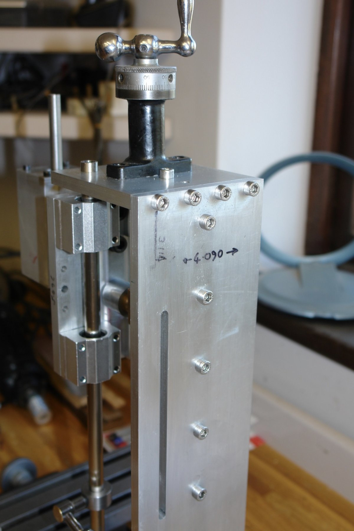
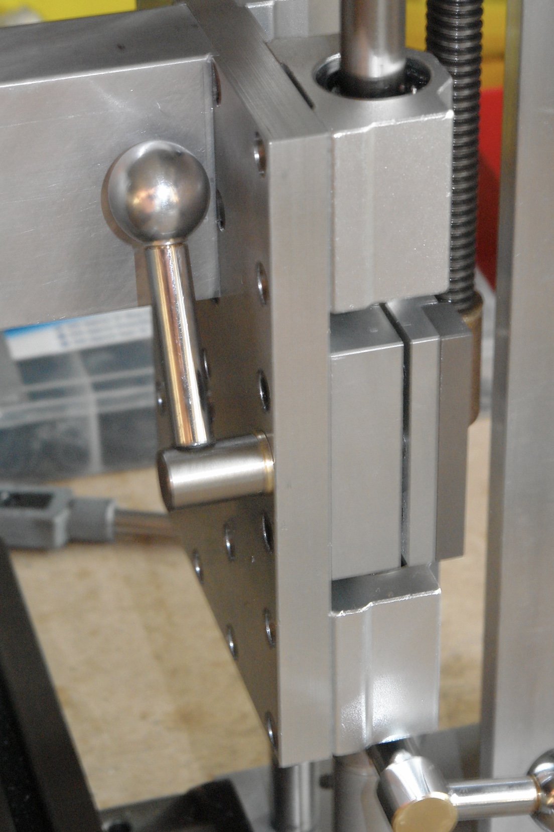
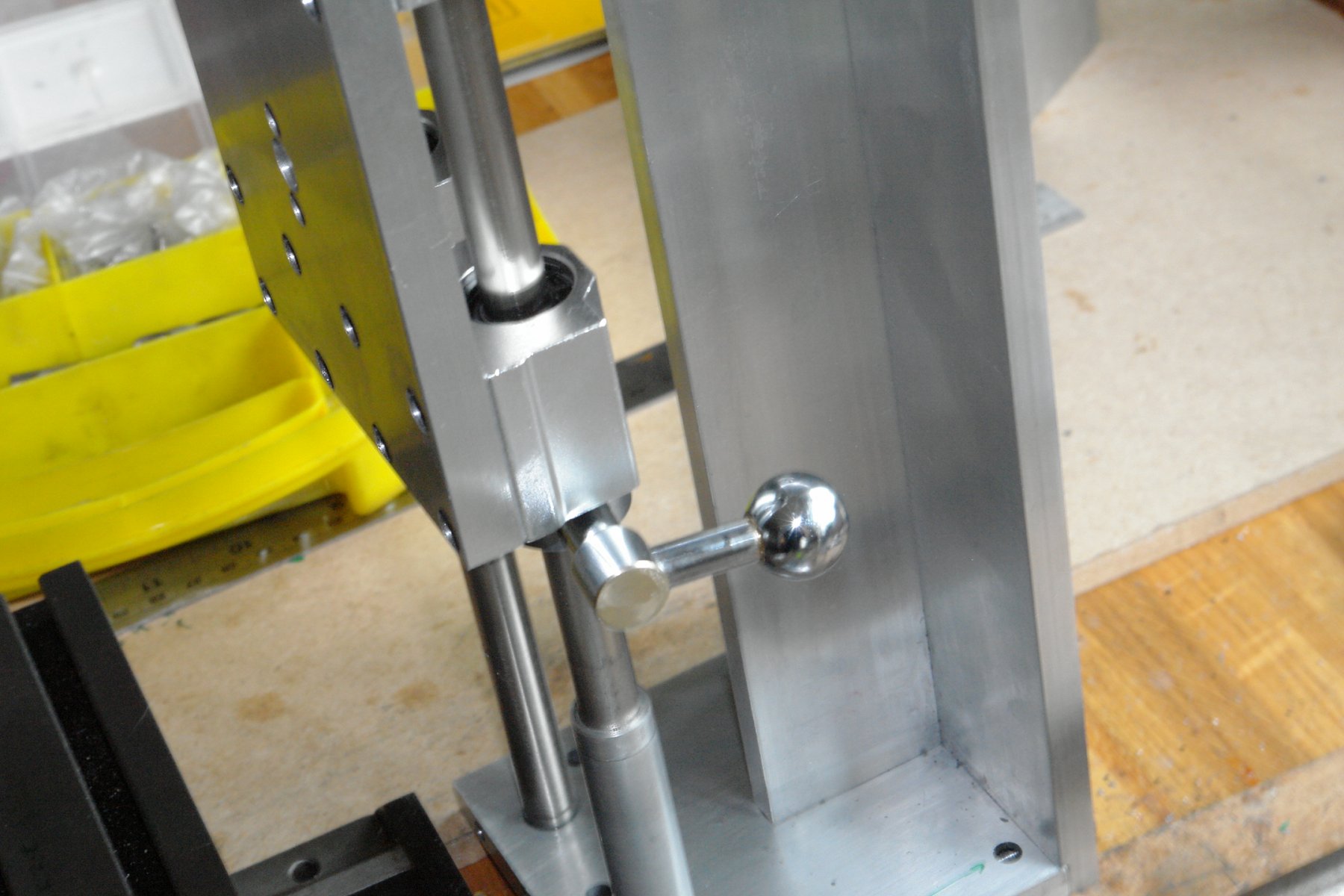
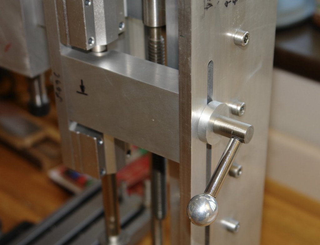
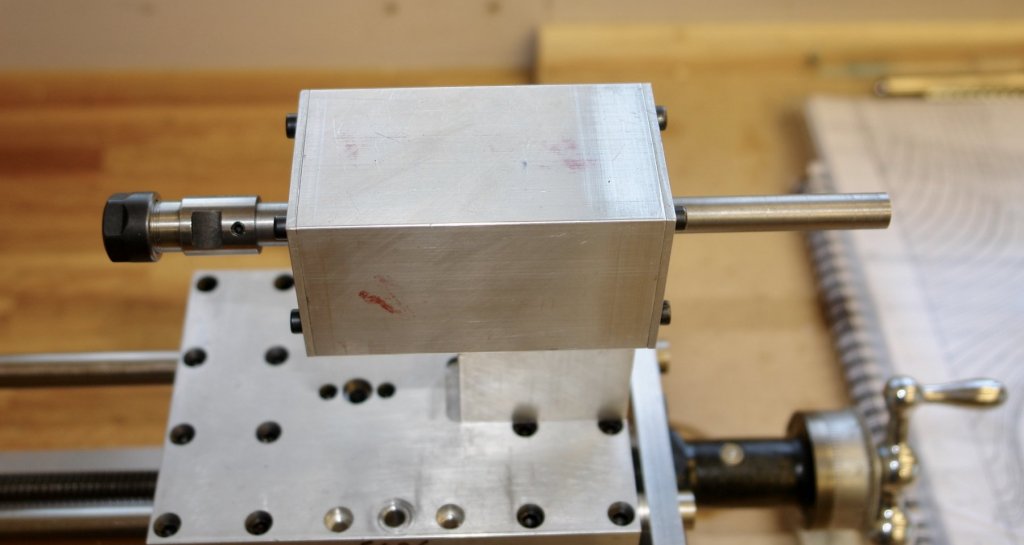
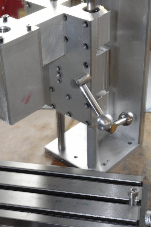
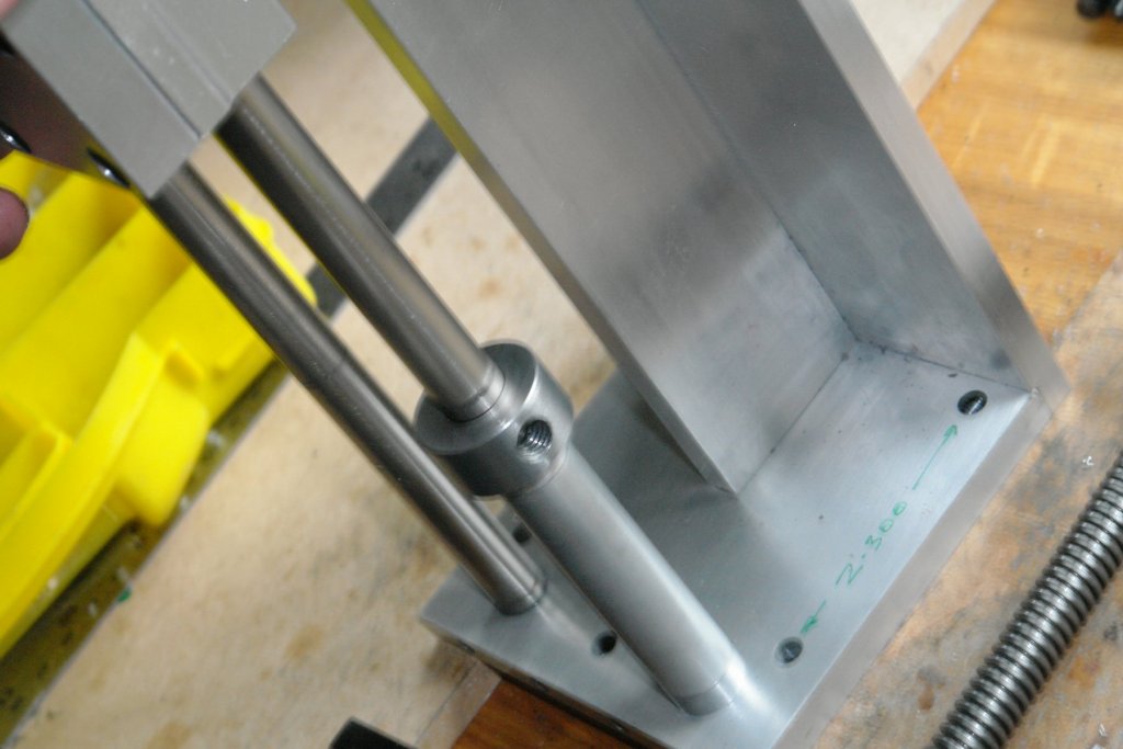
The column of the mill needed to be connected to the X,Y table. This was easily achieved by using 2 pieces of mild steel - 1" x 1/2" section which was drilled and tapped to match the holes in the table and column. I had previously made the vertical carriage clamp ( see earlier ). I felt however that I could increase the stiffness of the column by clamping the head directly to the frame of the column. The original clamp was thus dispensed with and the alternative design was manufactured. The revised clamp was made from 2" x 1" section aluminium. The semi-circular groove is necessary to clear the rods on which the head runs. The back plate of the column was slotted to take the clamping lever. The clamping lever was modified from the one made for the discarded clamp. The assembled clamp can be seen in the following photo.


-
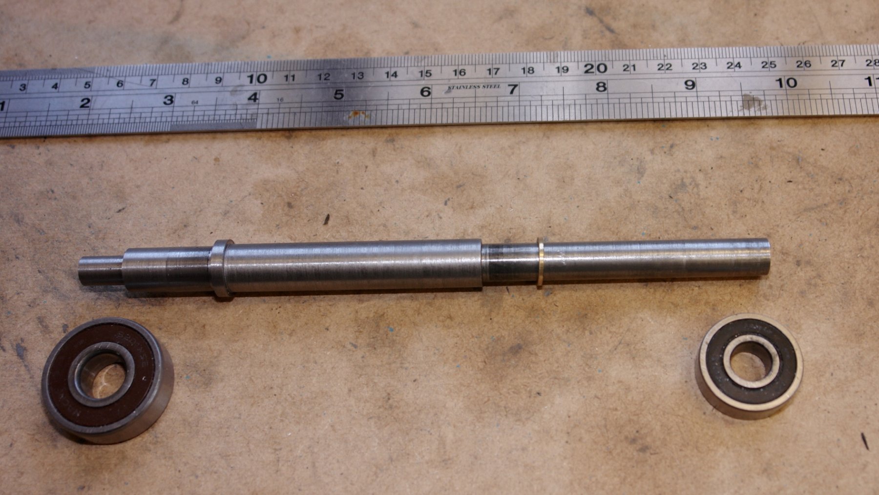
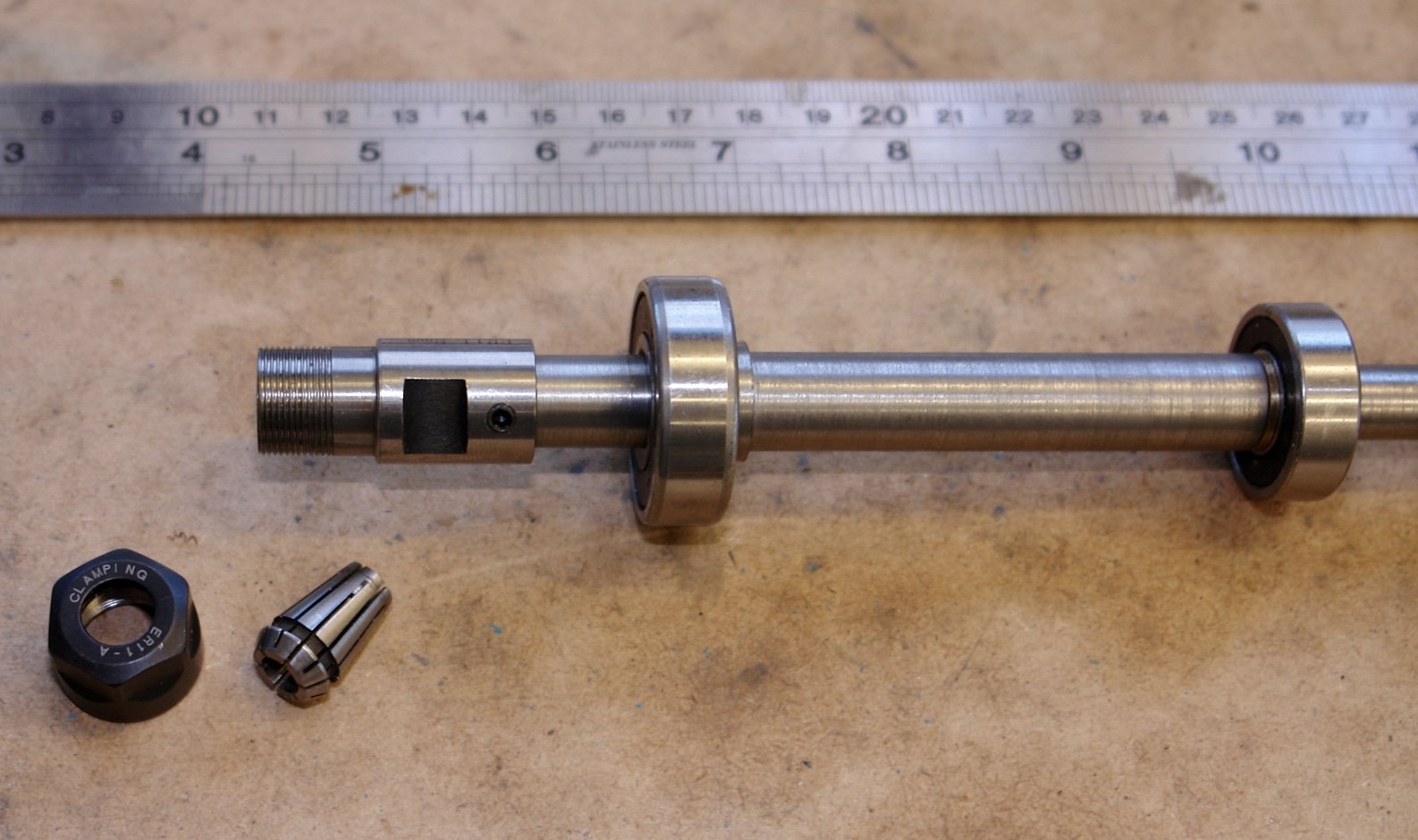
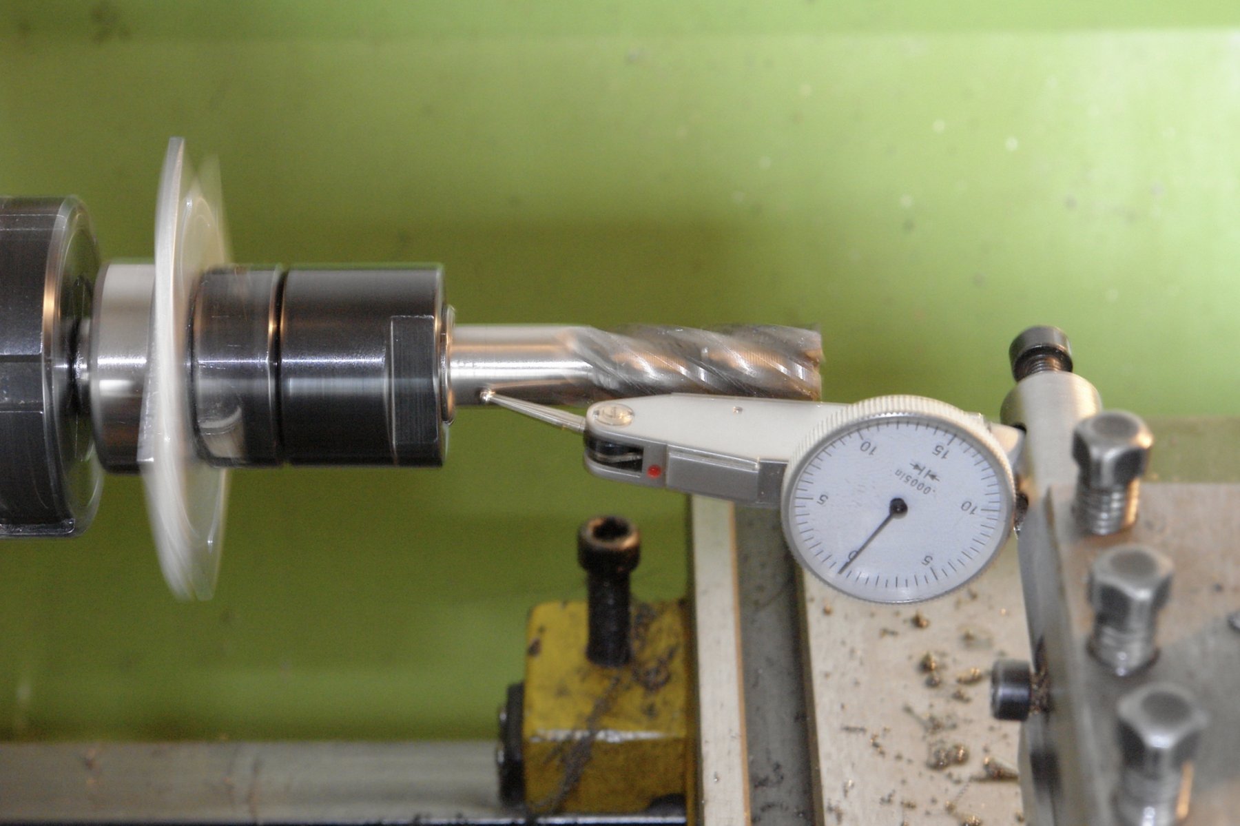
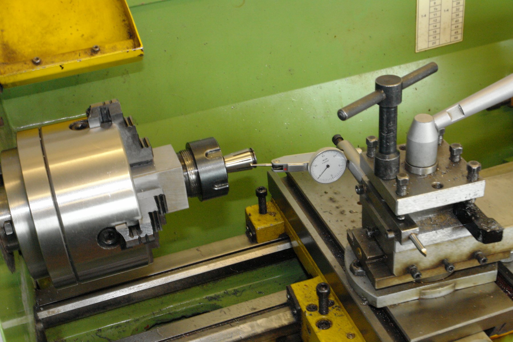
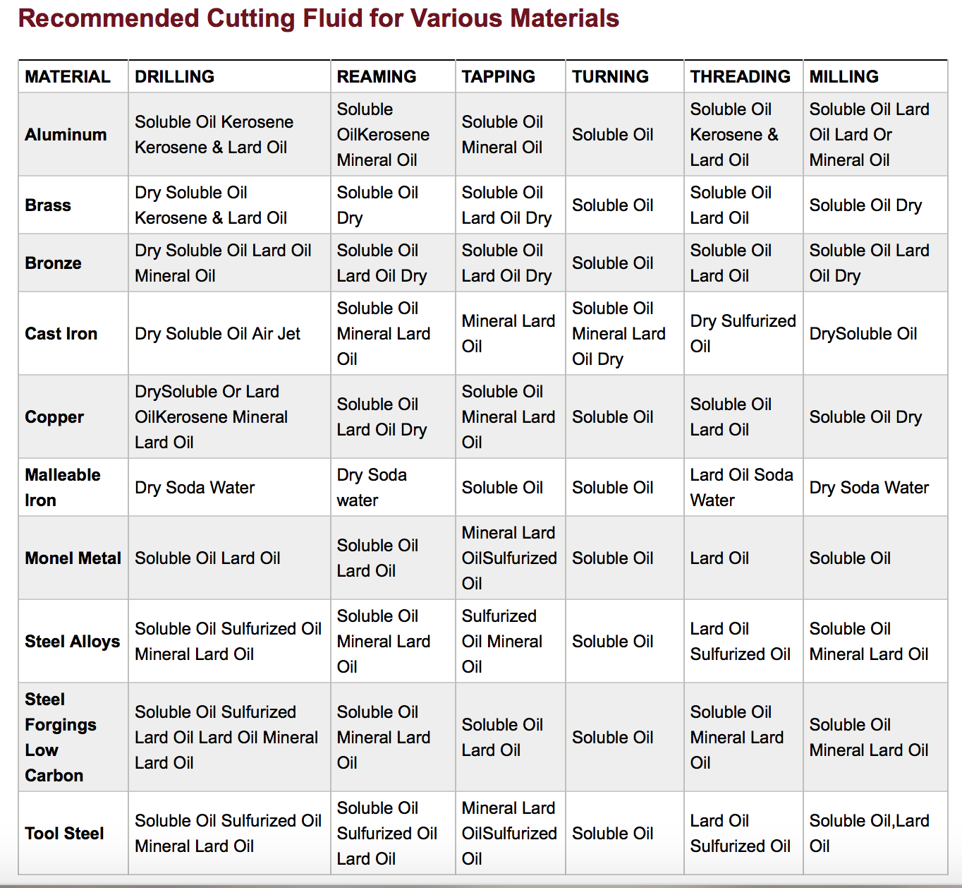
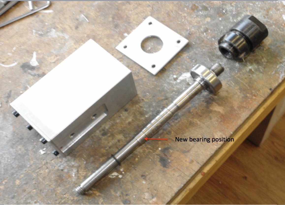
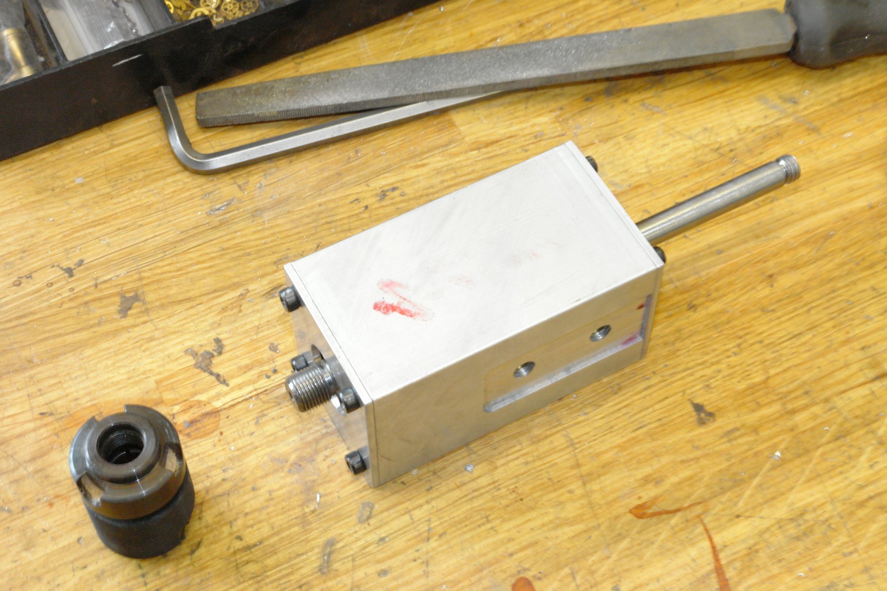
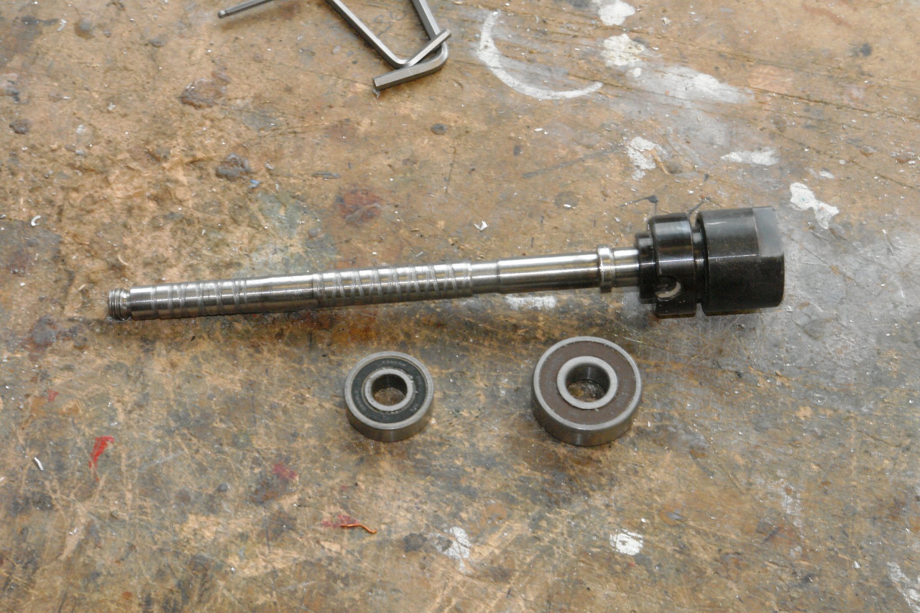
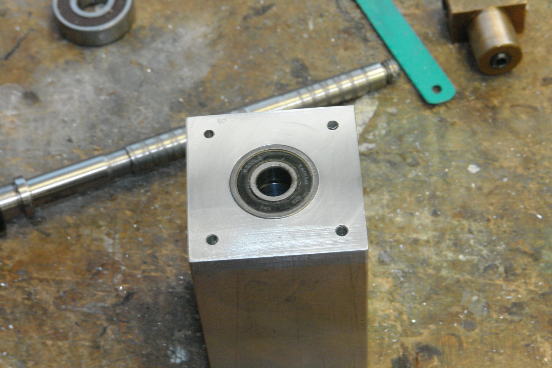
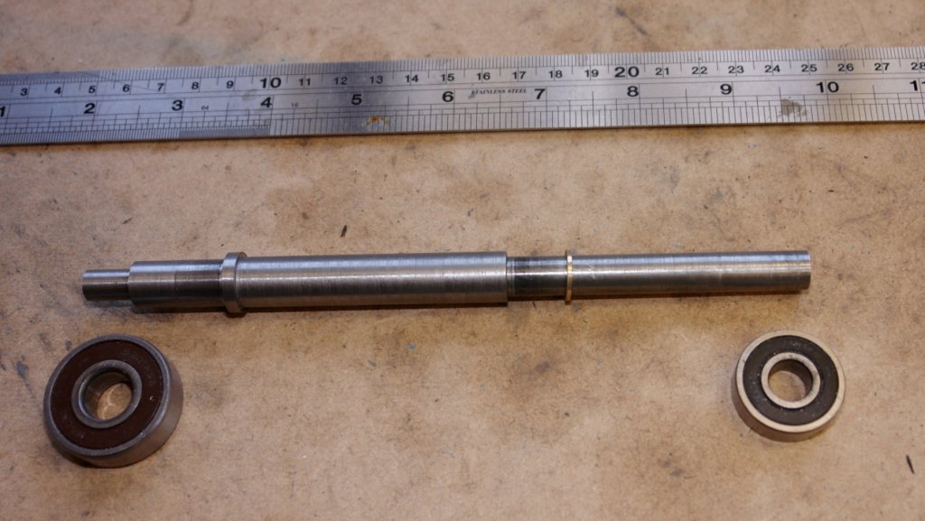
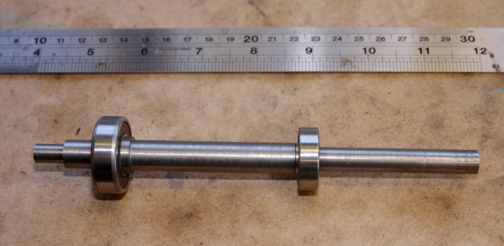
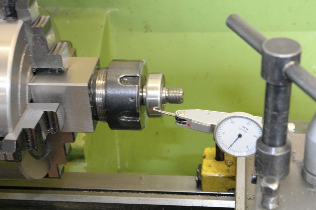
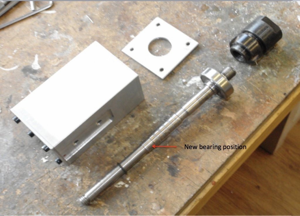
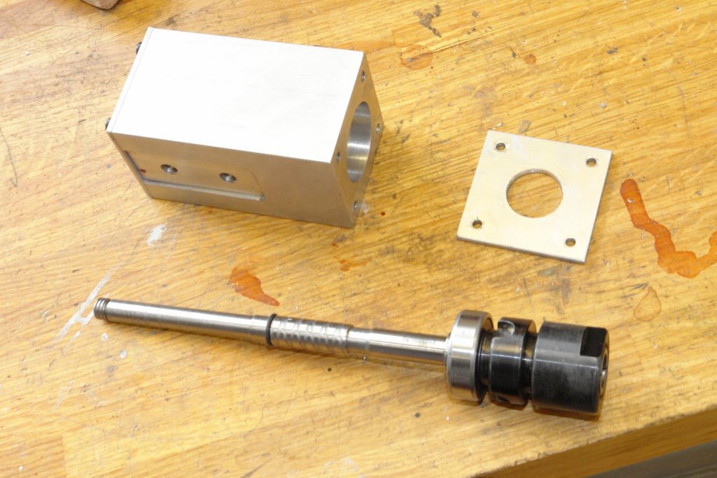
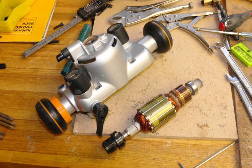
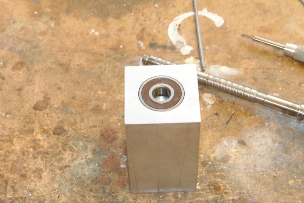
After an extended break I thought I'd better get back to finishing this thread. You may recall that I had been struggling with the shaft recovered from a Triton router. Having binned it I made a more substantial shaft by turning down a mild steel bar between centres. The bearings locate against the shoulders on the shaft and are fitted from either end. The brass ring in the picture is a spacer which allows the distance between the bearings to be finely tuned to match the spacing of the bearings in the head. A very good fit is required to eliminate any axial movement of the spindle during milling. The following photo shows the assembly with the spacer in place. Having thrown away the router spindle I also chose to dump the router chuck (it was a little big anyway). I bought a cheap ER11 chuck off eBay and turned down a spigot on the shaft to take this. The shaft was then mounted in the head and the bearings were secured using the 2 previously made retaining plates. I did the eccentricity check again and recorded minimal run out. Amazing how doing something the right way seems to give better results.

-
Richard / Moab Thank you both for visiting. I have been otherwise occupied for about 6 months, but i did manage to finish the mill in that time - I'll post the results as soon as I get a few minutes - hopefully later in the week. In the mean time I will also be sorting out the next model which I hope will be underway before Christmas. Keith
-
 good looking sails - very nice.
 -
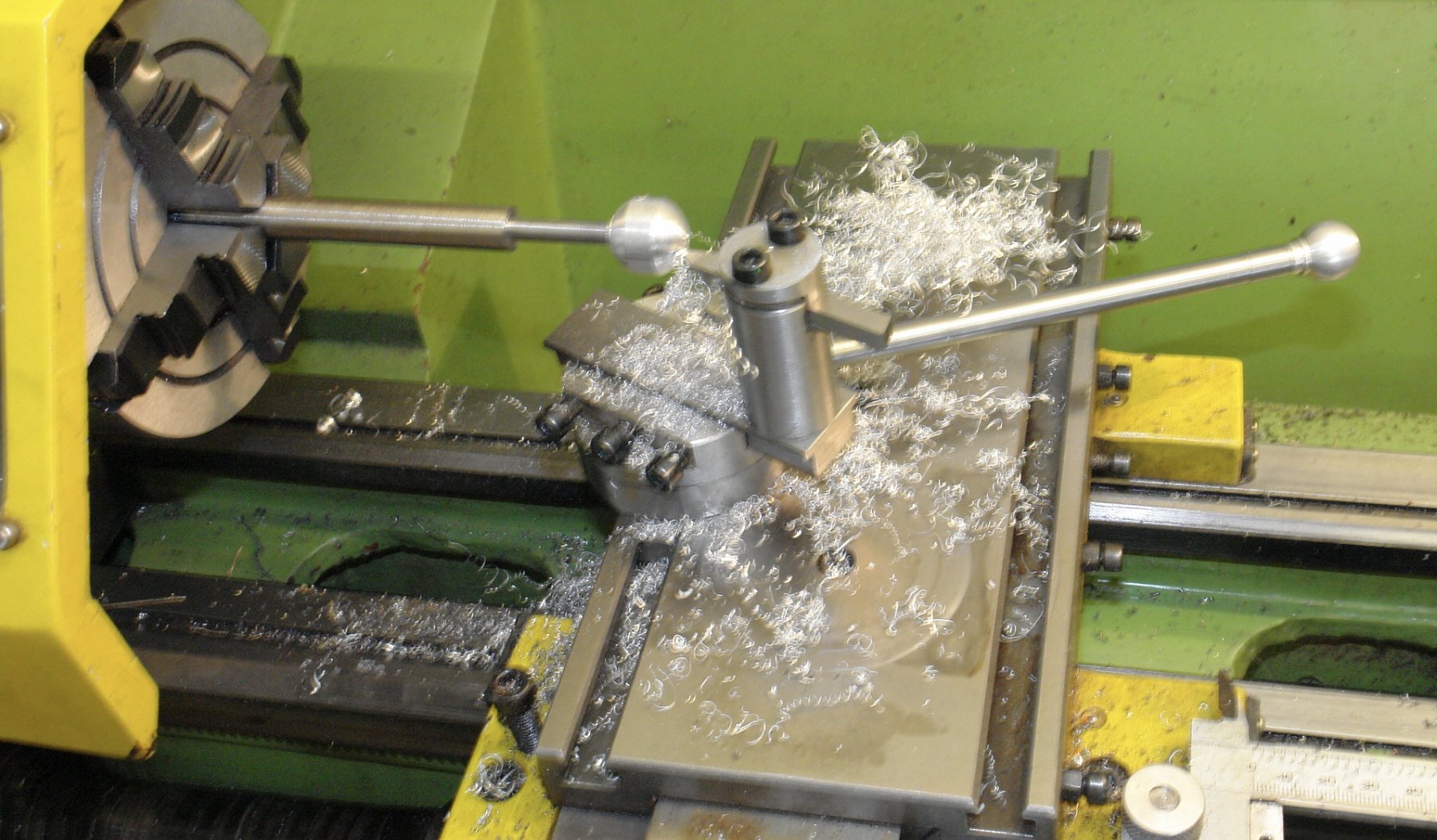
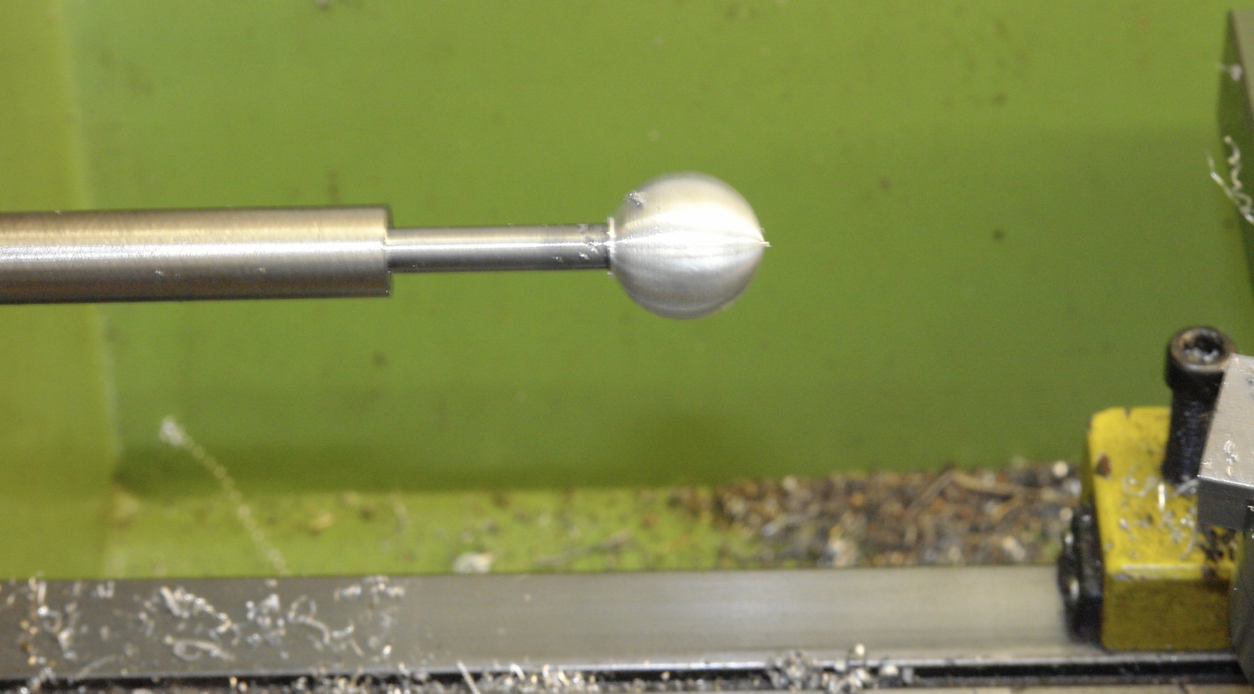
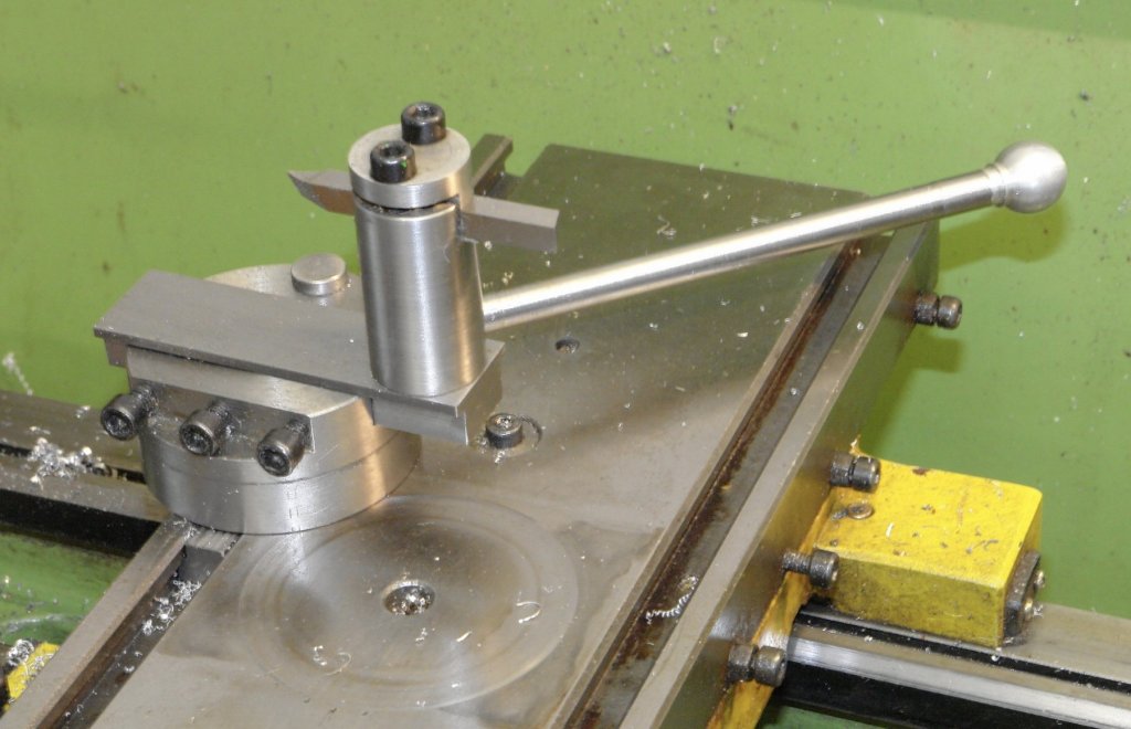
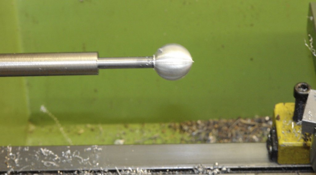
One step forward and two steps back seems to have been the motto for the last few days. One off builds tend to be that way and fixing / improving the design on the run is a necessary part of the process. I continued work on the carriage clamp and pressed into service my ball turning attachment that I made several years ago. I needed a ball for the end of the clamp handle. The funny thing about ball turning attachments is that they are always high on the must have list but are seldom used. In a little over 4 years this was its 4th outing. I do find the process quite satisfying. The clamp worked well, and with a bit of polishing the ball looked just the job. Unfortunately I subsequently decided I needed to stiffen up the slide assembly and the design for doing this involved a different clamping arrangement - so this work was wasted. I then measured the run to on the spindle and it was a deal greater than I thought necessary - about .003" eccentricity. So followed a day tracking down the problem. On inspecting the collet i realised the bore was rough and did not run true when measured with the dial indicator. I decided to re machine the internal taper. I set the topside to the correct taper angle using one of the collets as a reference for the dial indicator. I then machined the taper angle in the collet bore. I then rechecked and found that the eccentricity had only improved marginally. I continued to check and even checked the bearings were running true - they were!!! Having eliminated all other possible causes I was forced to conclude that the bearing seats on the shaft were at fault - you may recall from earlier I had re machined one. If I had started from scratch I would have turned the shaft between centres, but I took a short cut. The shaft is now in the bin and I have dug out a bar from which to make a new one by the correct method!!!!!! So in summary most of the work over the last few days (like the shaft) is in the bin.


-
Patrick, they don’t make them like they used to. Can’t wait to see what you imagine to be inside. Perhaps warp engines with dilithium fuel bunkers.
-
John, I was pleased to see the update. The final version of the sail looked great and the use of shell was fascinating. Your self control during the fan incident demonstrates excellent marital skills but you might consider buying her flowers, as a thank you, and to encourage her to do it again.
-
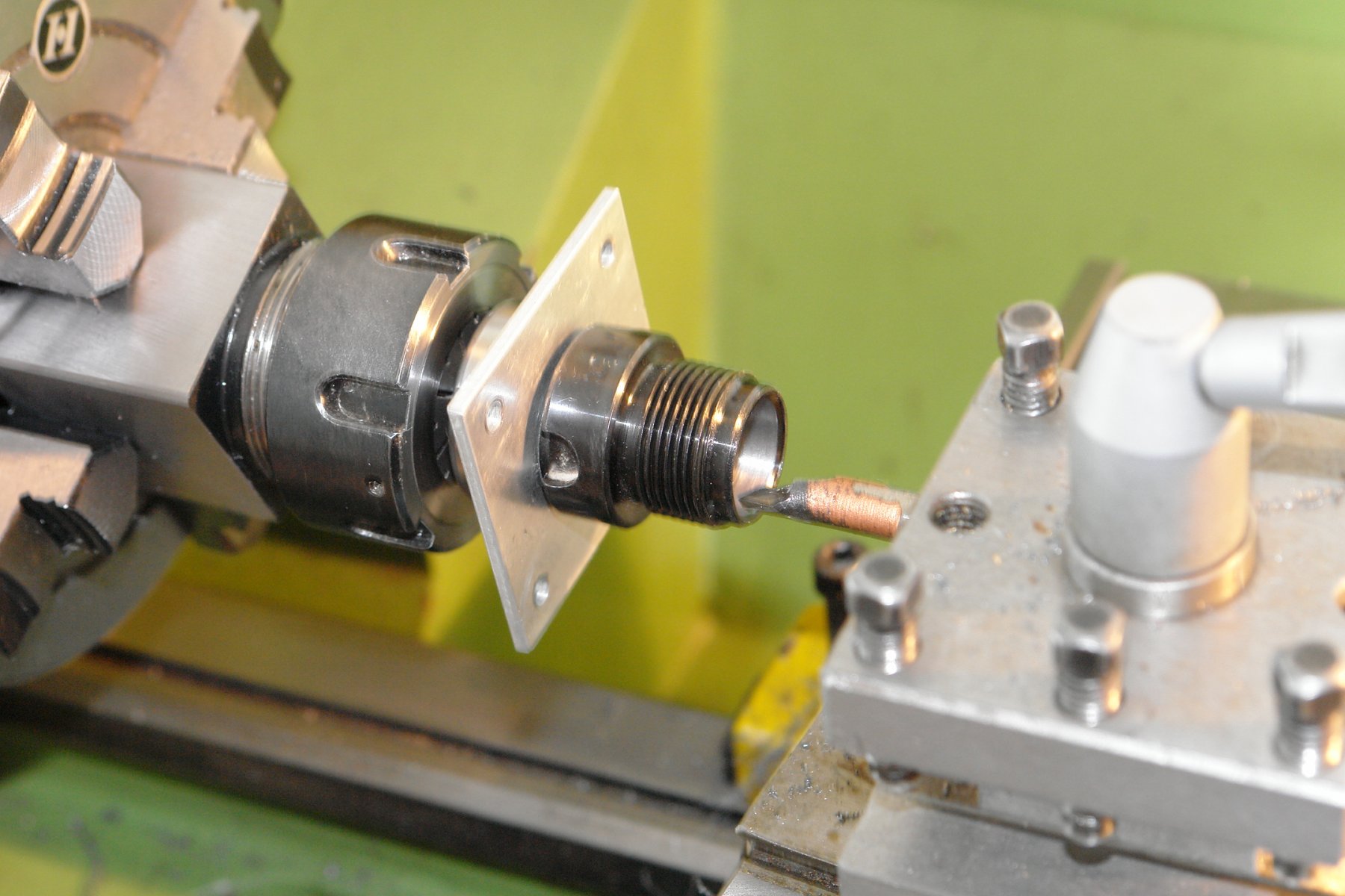
Machining copper stock.
KeithAug replied to mtaylor's topic in Modeling tools and Workshop Equipment
Mark - I'll be interested to how you get on with copper. -
Machining copper stock.
KeithAug replied to mtaylor's topic in Modeling tools and Workshop Equipment
M Mark, lard is animal fat Lard oil is the clear, colourless oil pressed from pure lard after it has been crystallized, or grained, at 7° C (45° F). It is used as a lubricant, in cutting oils, and in soap manufacture. ... Lard oil has excellent lubricating qualities, but it tends to become rancid -
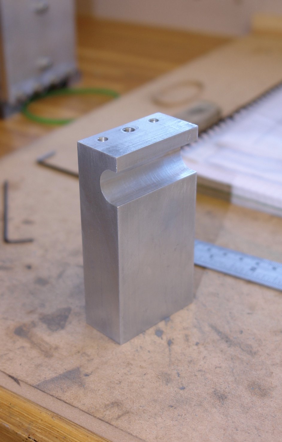
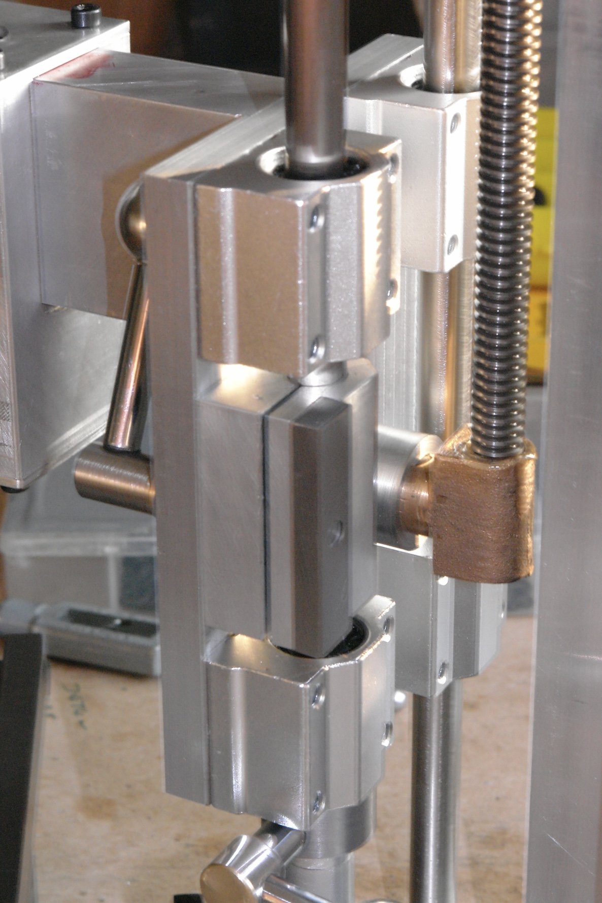
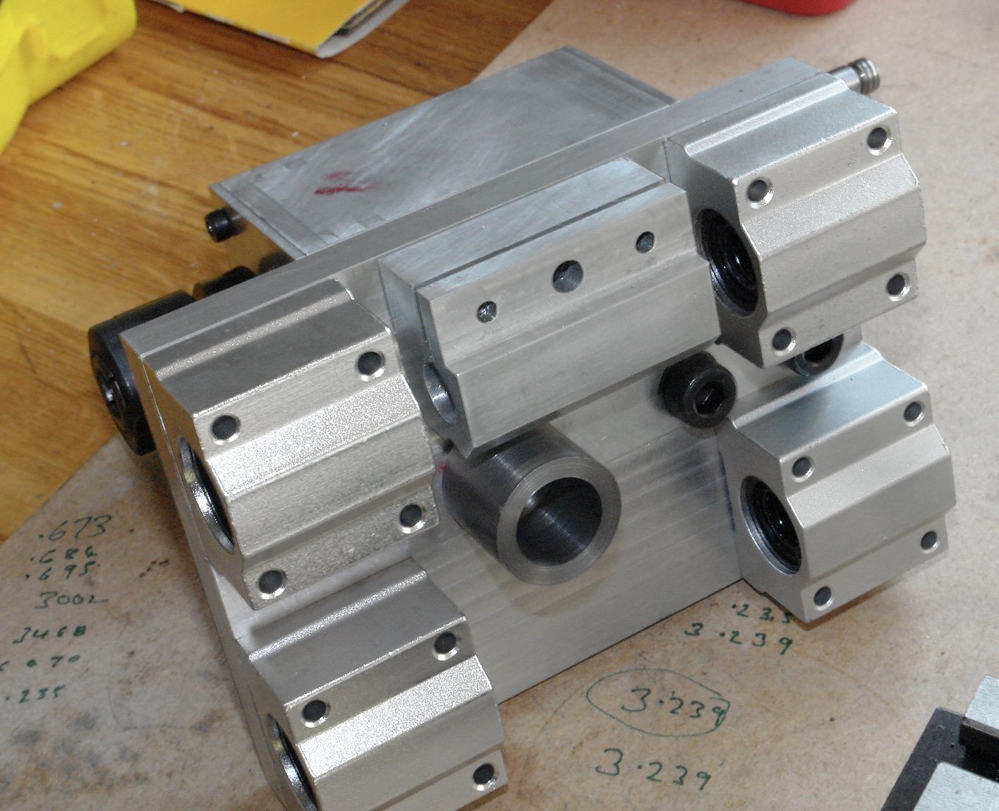
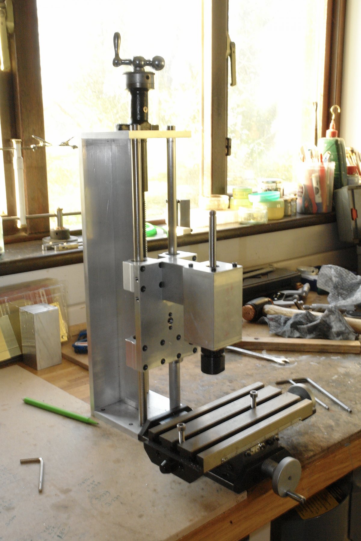
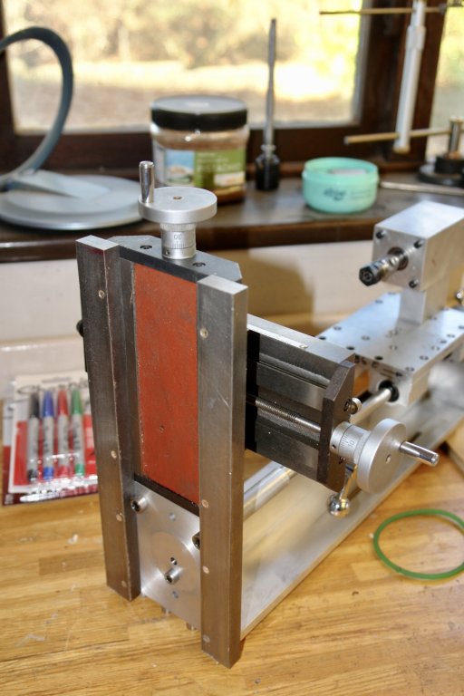
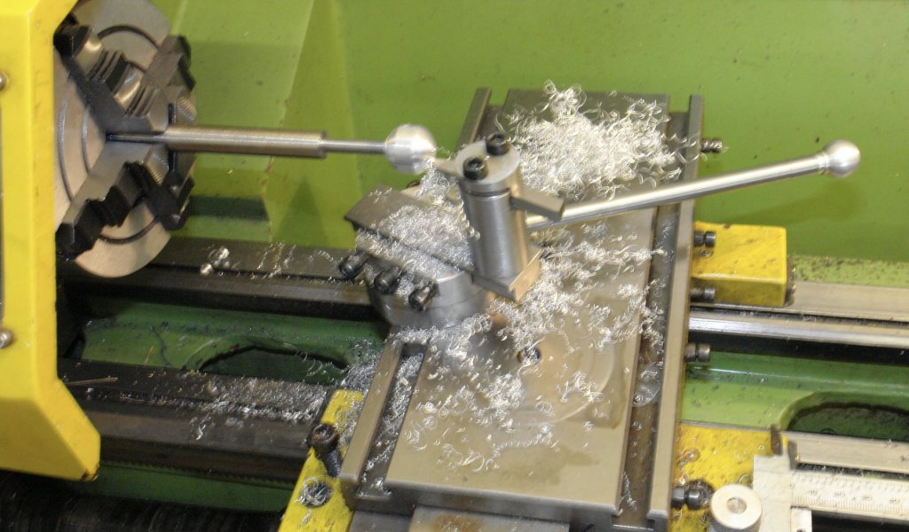
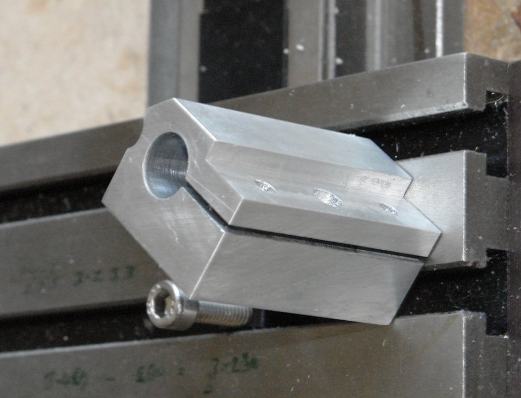
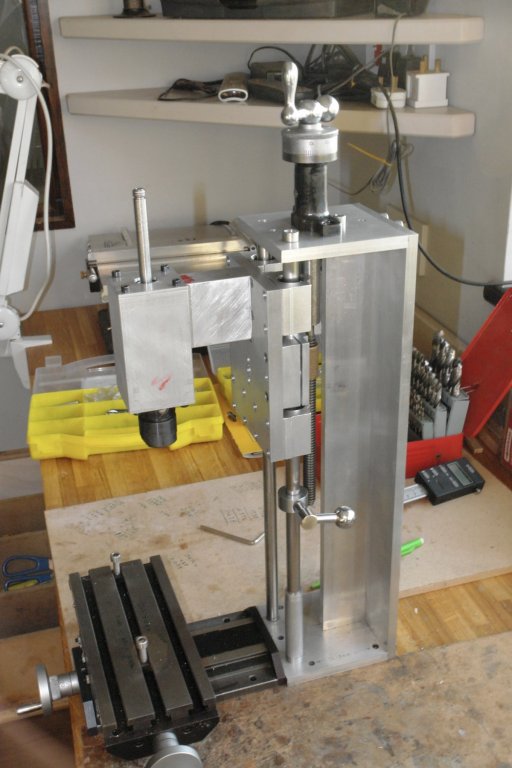
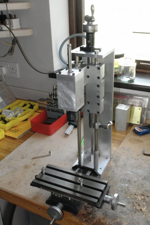
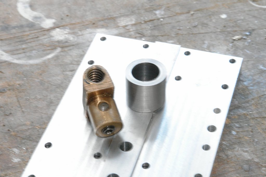
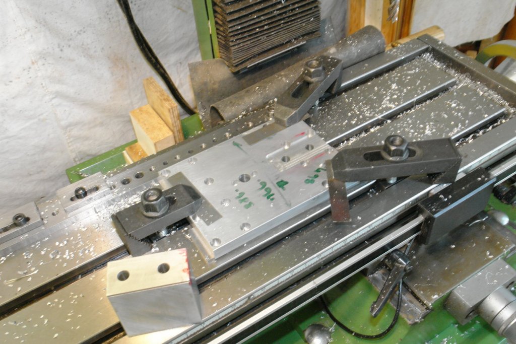
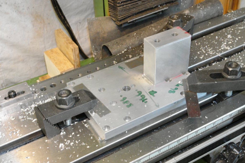
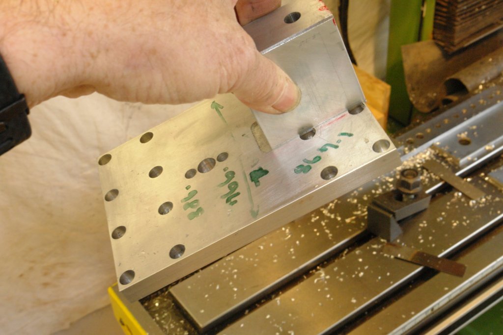
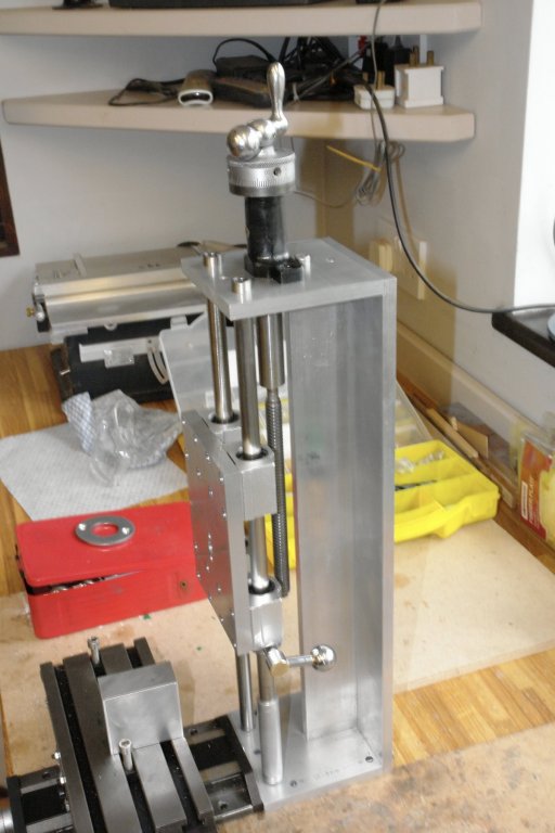
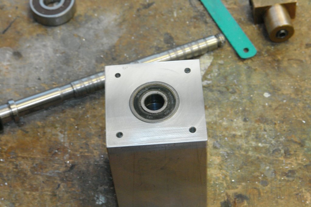
Thank you Mark. Today the temperature outside was 25 deg c (77 deg f). If felt hot but fortunately the workshop only got to a comfortable 16 deg c. I reached a bit of a milestone in the build. I made the carriage lock for the sliding plate and attached it to the plate with 2 bolts (the 2 smaller holes). The locking handle has still to be made and uses the larger centre hole. With the lock attached I was able to bolt the bearing housing to the sliding plate. I was then able to assemble the milling head on to the runners. The leadscrew and nut were then assembled. Finally I have something that starts to look like a mill. The head now moves smoothly and securely in response to the turning of the leadscrew - very satisfying. I took a couple of further shots to show maximum and minimum elevation.


-
Machining copper stock.
KeithAug replied to mtaylor's topic in Modeling tools and Workshop Equipment
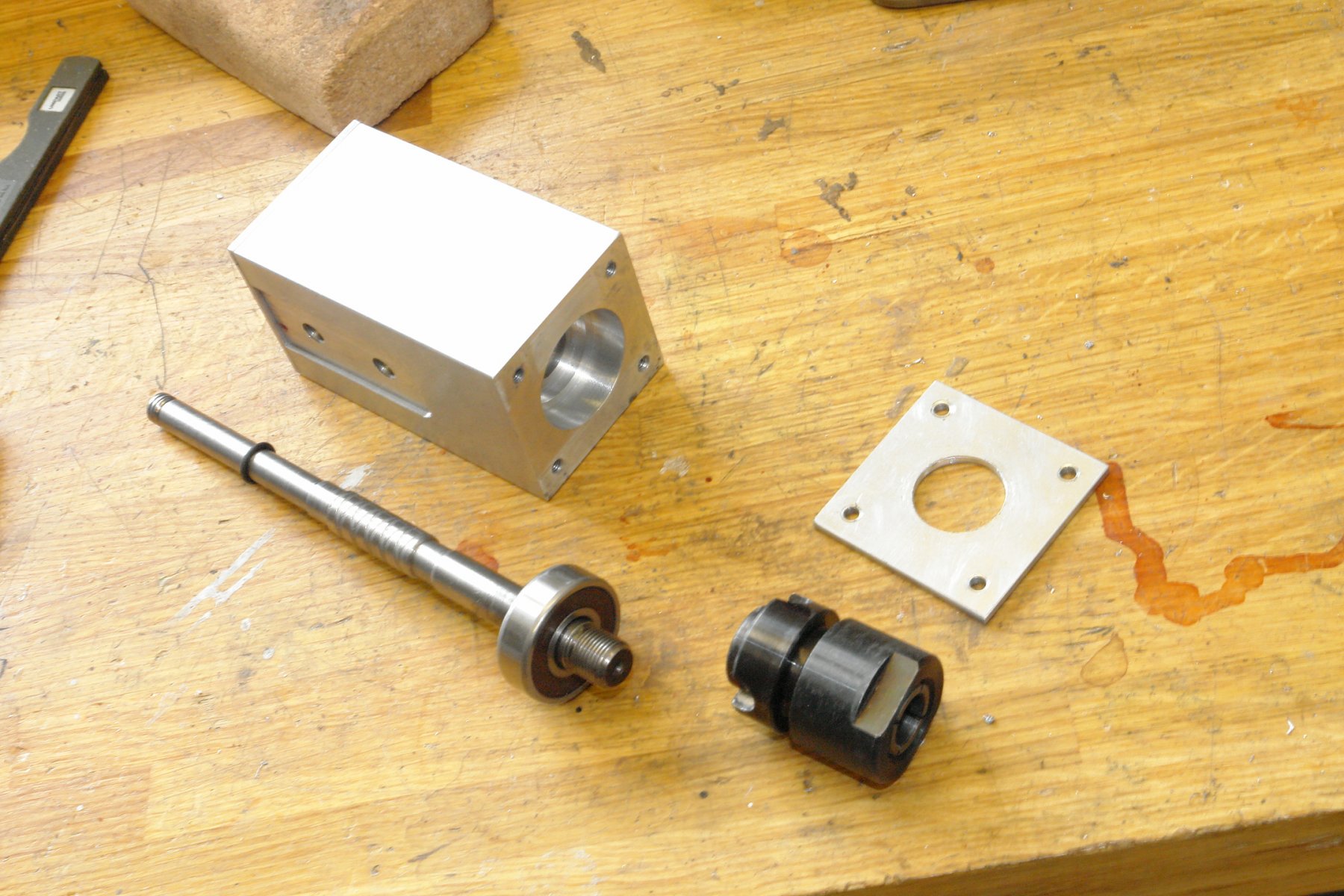
Mark - copper can be quite tricky - it work hardens quite quickly and pick up on the tips of tools can give a poor finish. Because it is very soft it can also be prone to snatching at the tool. My advice would be to use HSS tools which are sharpened to good edge. My preference is to use cutting oil as i think it lessens the tendency for pick up and snatching - as a result gives a better finish. But here is what the experts say:-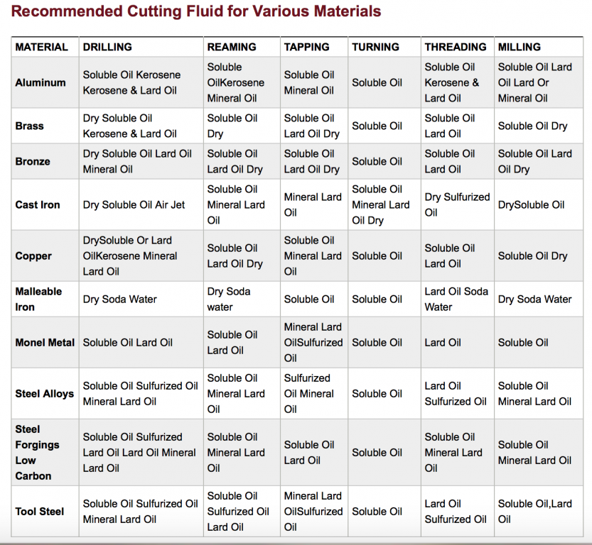
-
Dave, the strips of wood with angled cuts look like they are the sides of stairs. The treads go in the slots.
-
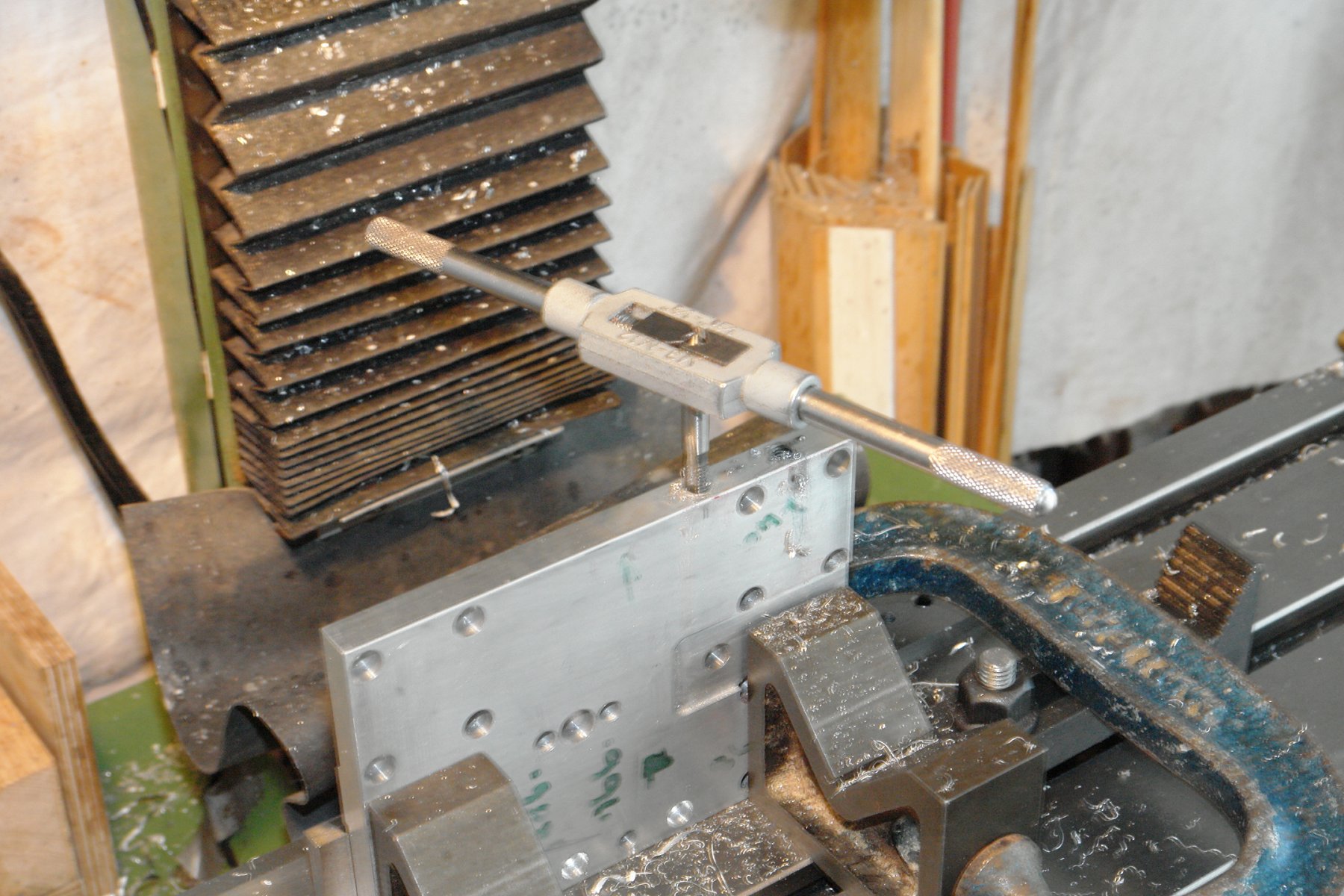
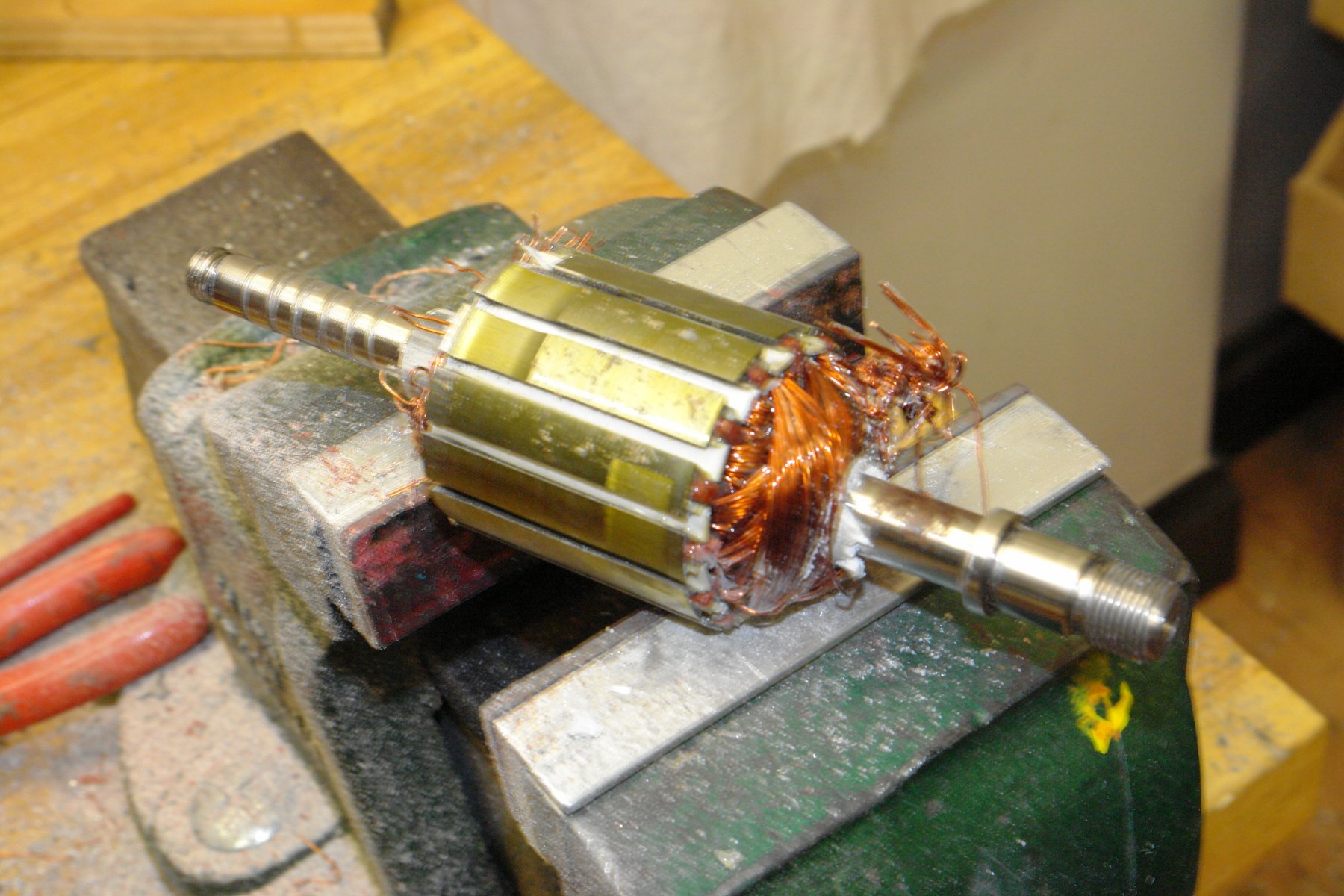
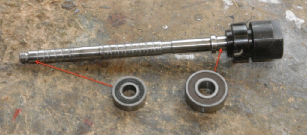
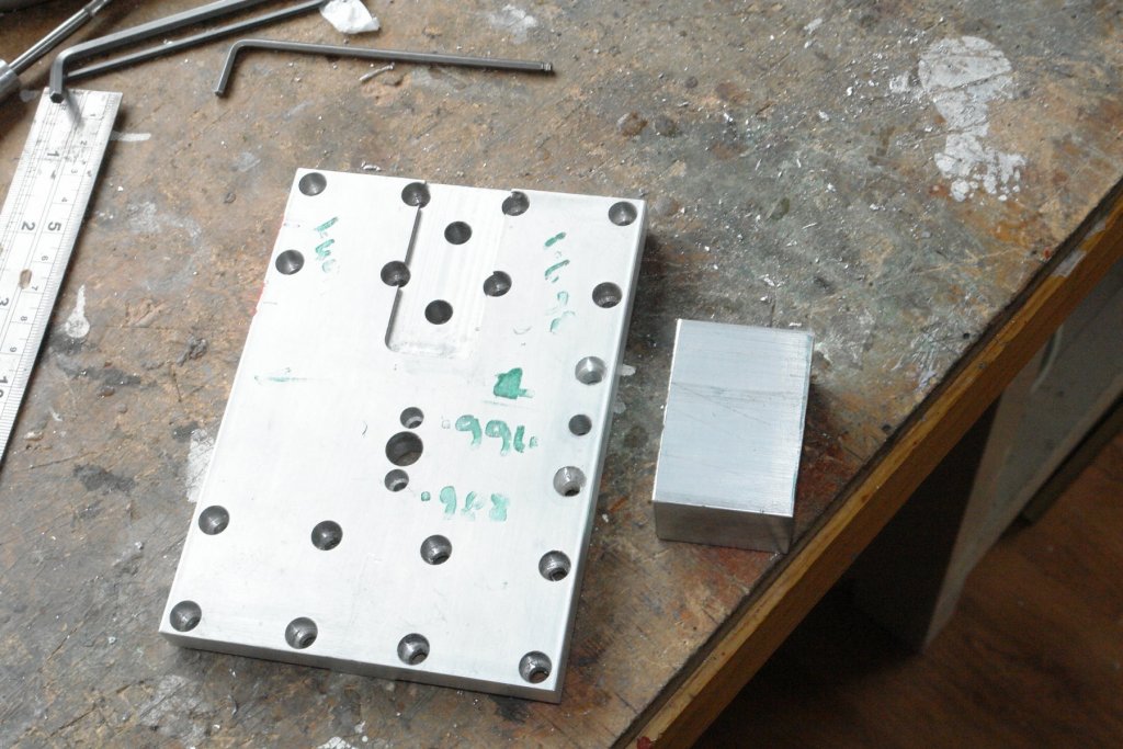
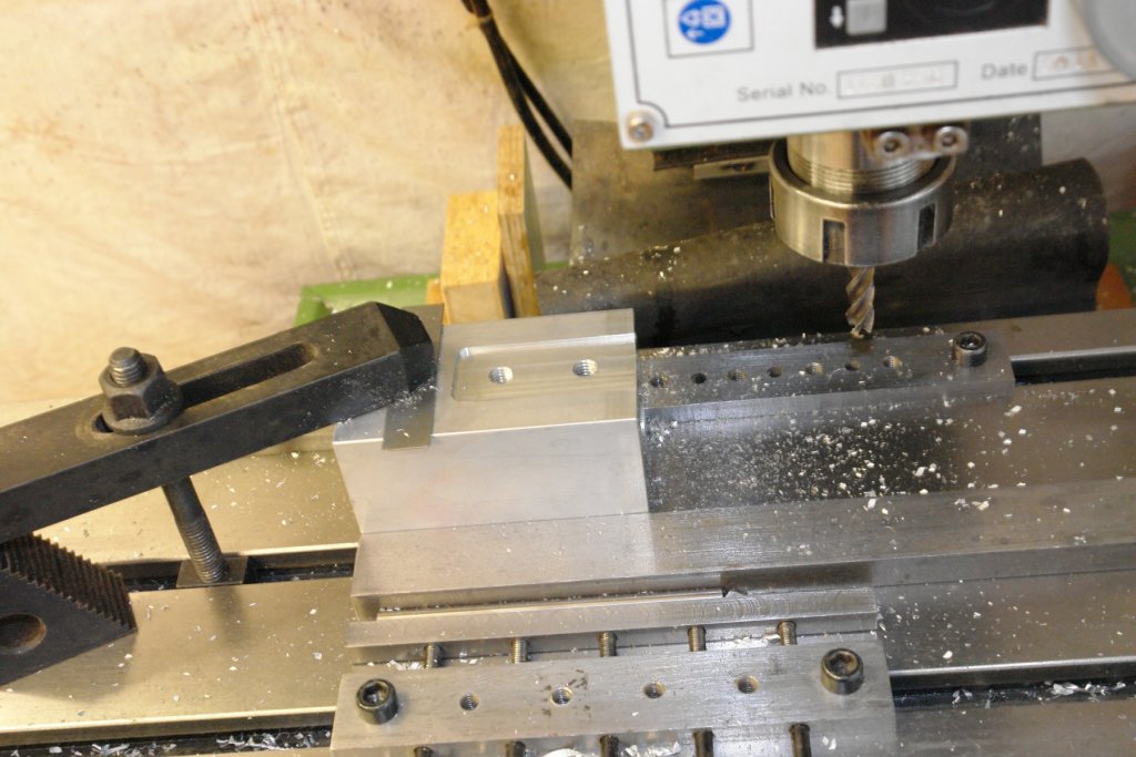
Lovely day here - bright sunny and 24 deg centigrade, only 2 weeks ago I was walking in snow - thats British weather for you. More progress - the spindle is now done. The spindle as removed from the router had bearings at the extreme ends:- The spindle had been machined so that both bearings were press fits (and as a consequence took some getting off). I used the lathe tailstock as a press to replace the lower (chuck end) bearing The distance between bearings was circa 6 inch. I wanted the bearings on the mill spindle to be circa 3 inch apart so I needed to turn down the shaft. Easier said than done as the shaft turned out to be as tough as old boots. My preferred HSS tools struggled to cut it and I was forced to press my TCT tools into action. Even then it was a slow process requiring plenty of cutting fluid. Anyway some time later:- The outer races of the 2 bearings are clamped axially in the bearing block and the inner race of the lower (chuck end) bearing is rigidly clamped to the spindle. Consequently the newly machined seat for the upper bearing needed to be a sliding fit. The shoulder on the shaft is about .010 short to allow for the expansion of the spindle relative to the bearing housing. The spindle / bearings were then mounted in the housing and the chuck was replaced. The chuck is treaded such that the action of the cutter is to tighten it on to the spindle. The spindle shaft sticking out of the the top of the bearing housing will be used to mount drive pulleys - currently I think 3 pulleys. The spindle feels nicely tight with no unwanted movement. I next needed to make the carriage lock for the vertical slide. This will be bolted to the slide plate and will clamp round the right hand slider bar. Three more holes were drilled in the slider plate and the block for the clamp was cut from 2" x 1" bar. The final operation on the slide plate was to machine and tap holes in the upper left hand edge to take the mounting for the motor (yet to be designed). Fortunately I think that is the end of machining on the sliding plate, it is already looking a bit like a Swiss cheese. I also mounted the boss on the back of the slide plate that attaches to the leads crew nut. The leads screw nut is fastened in place by the grub screw in the end which via a taper pushes out the pin on outside diameter. this clamps the lead screw into the bore - see phot.


-
Druxey - thank you - and an interesting point you raise. In the UK periodic table its aluminium:- Is it aluminum in the Canadian table?

-
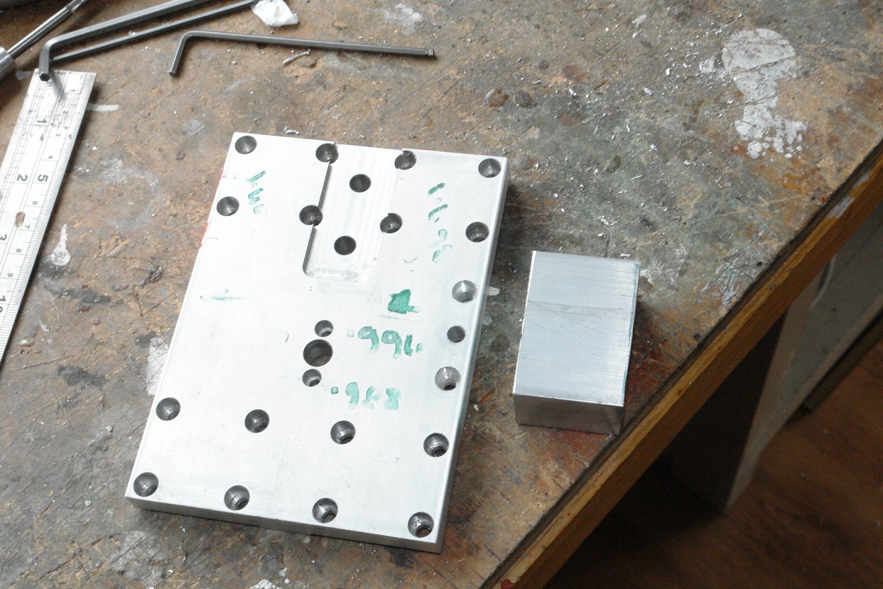
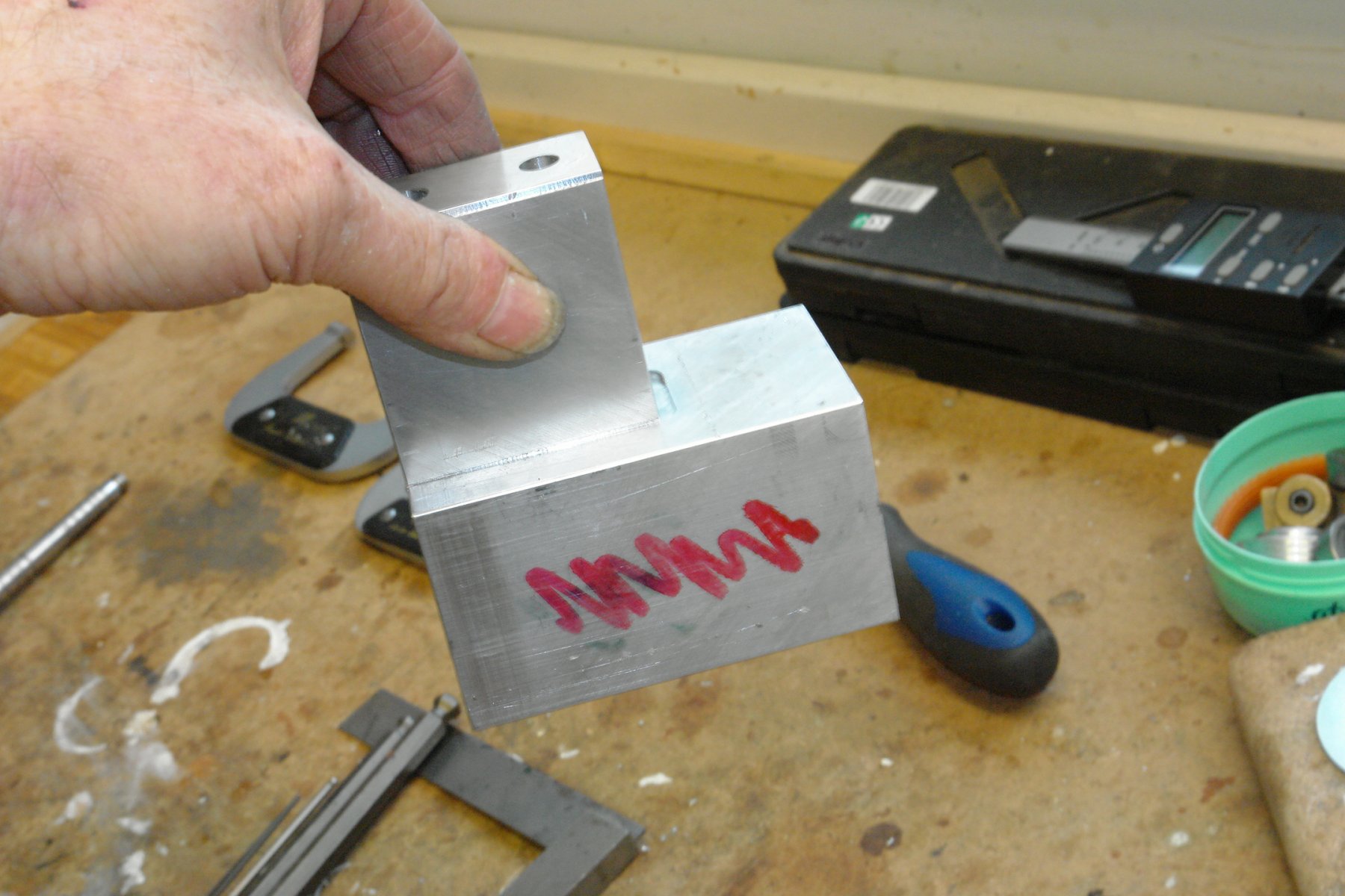
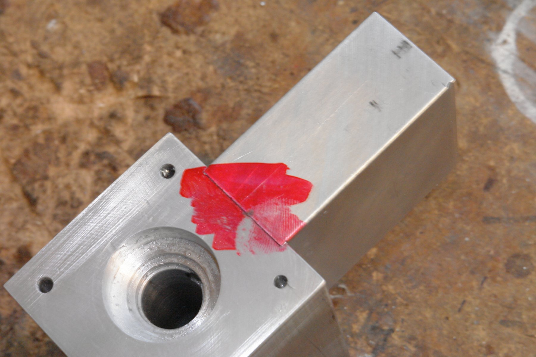
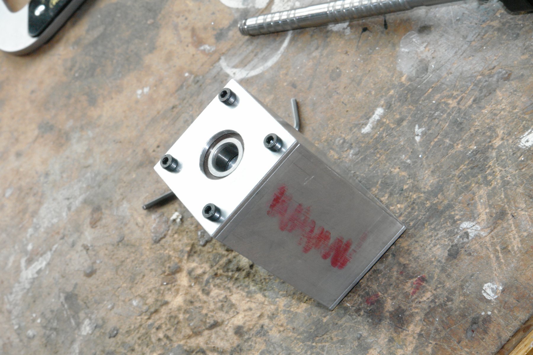
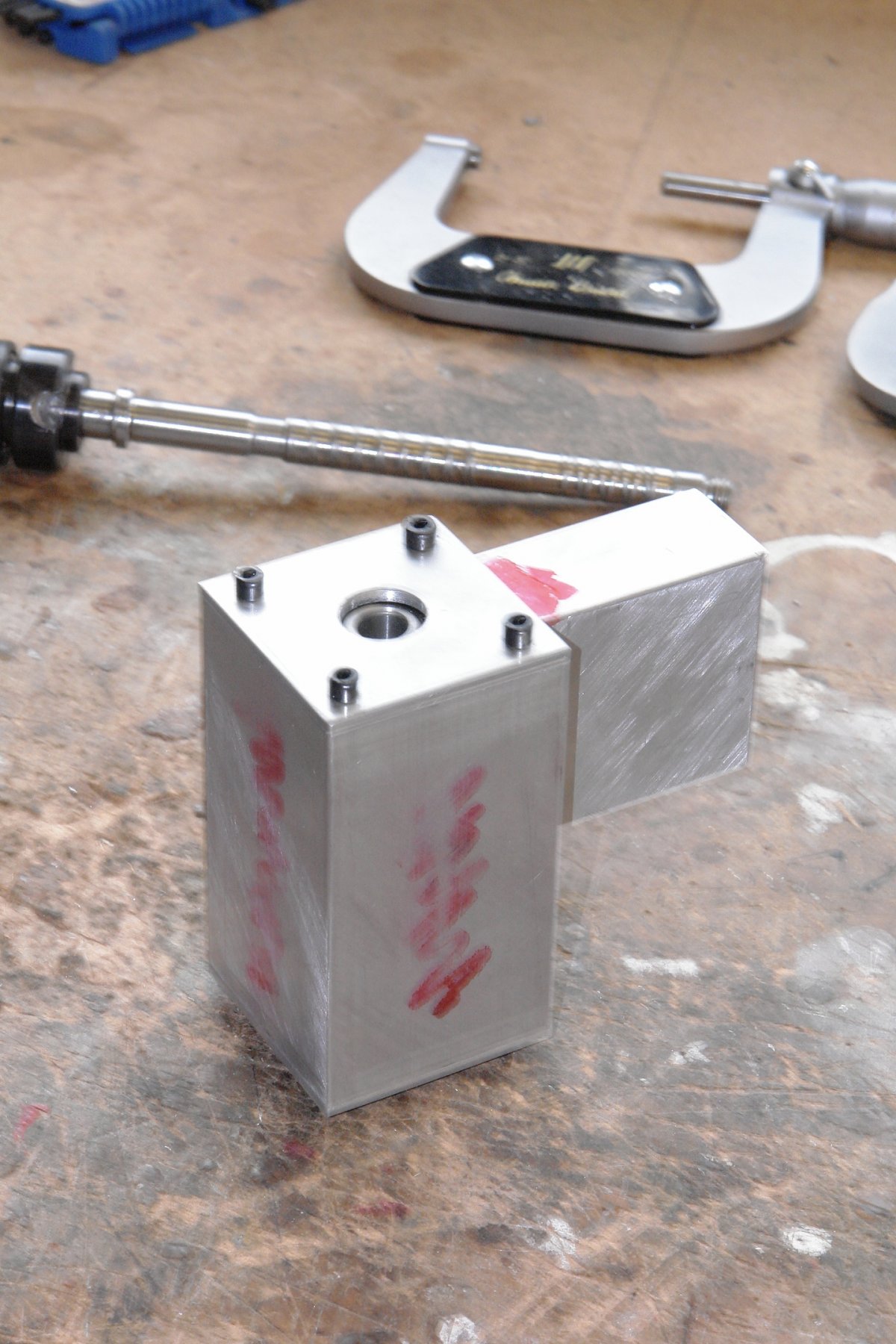
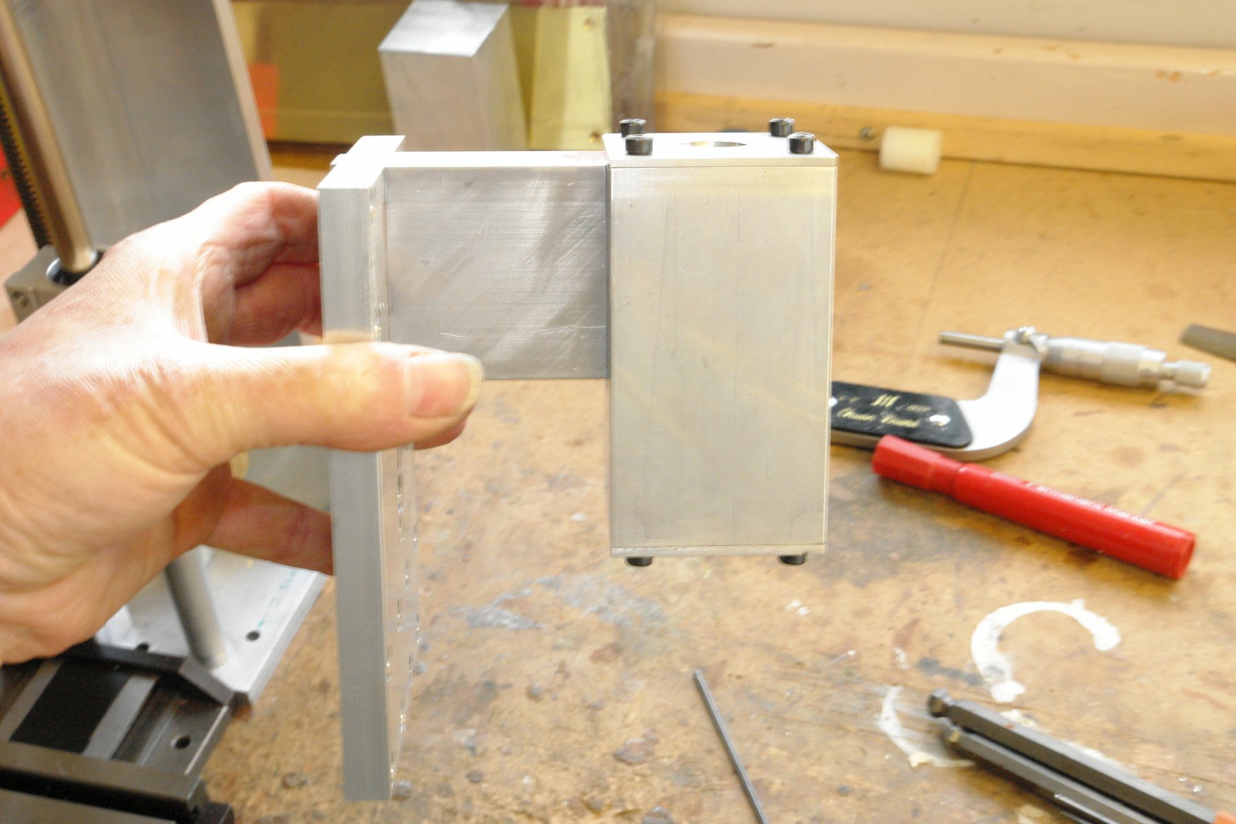
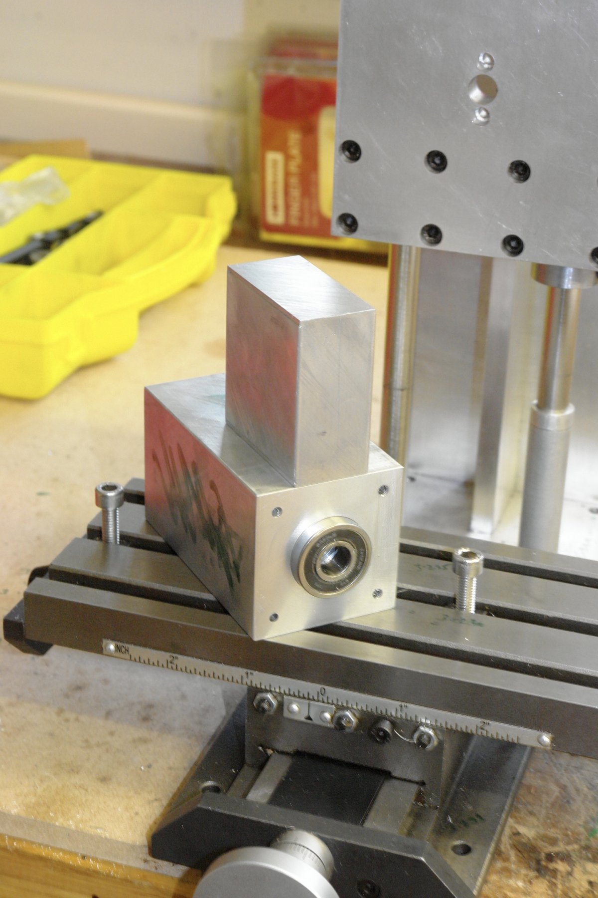
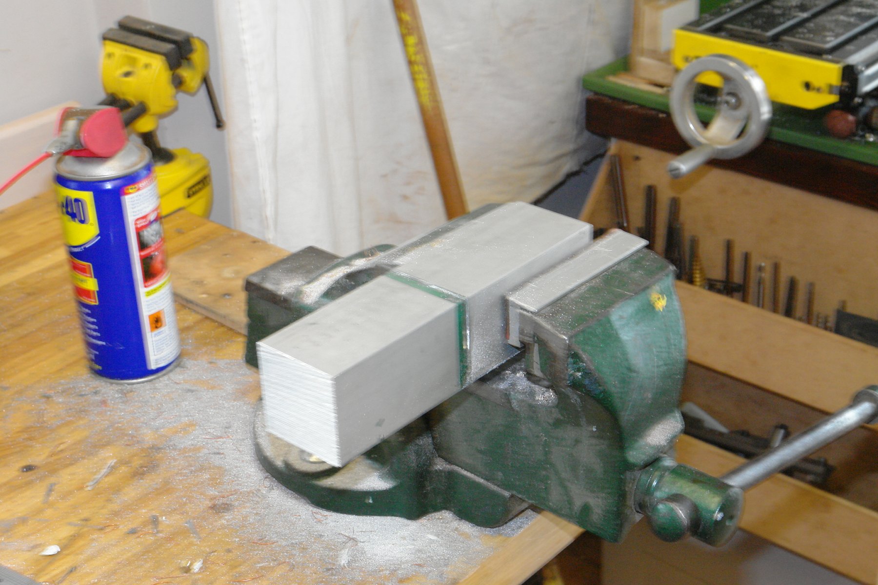
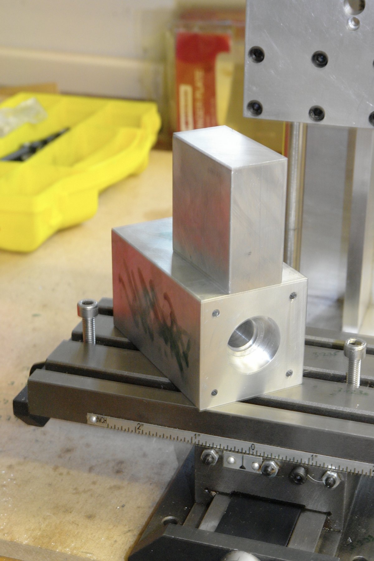
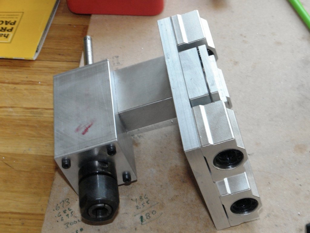
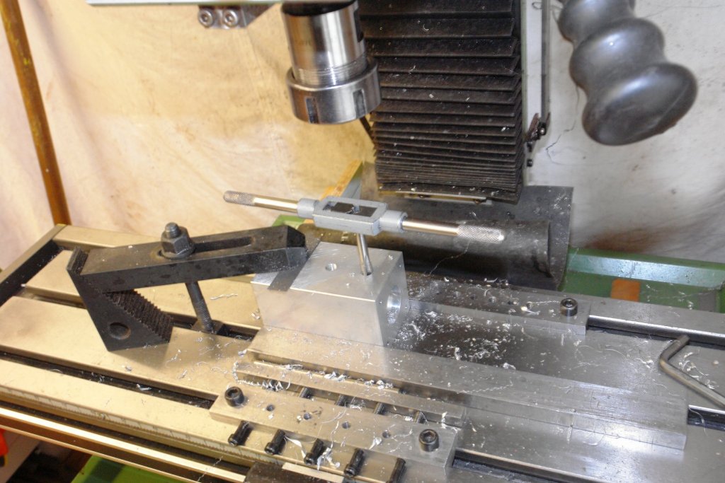
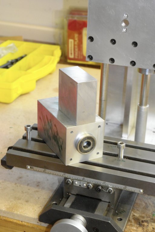
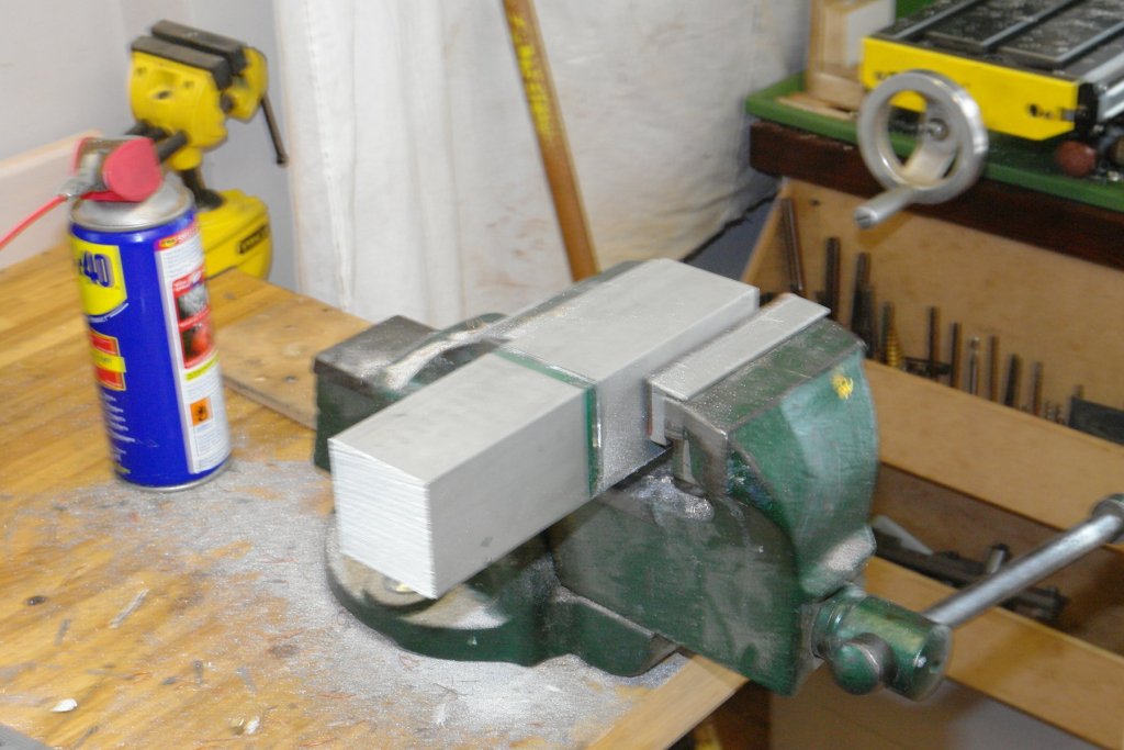
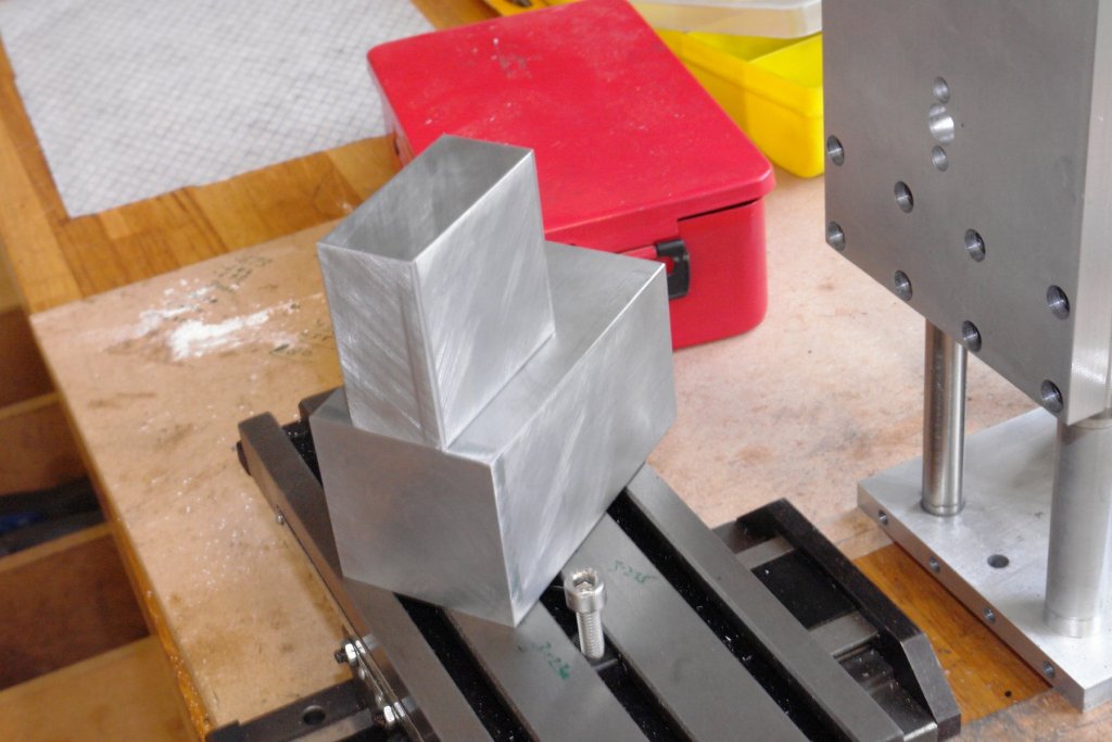
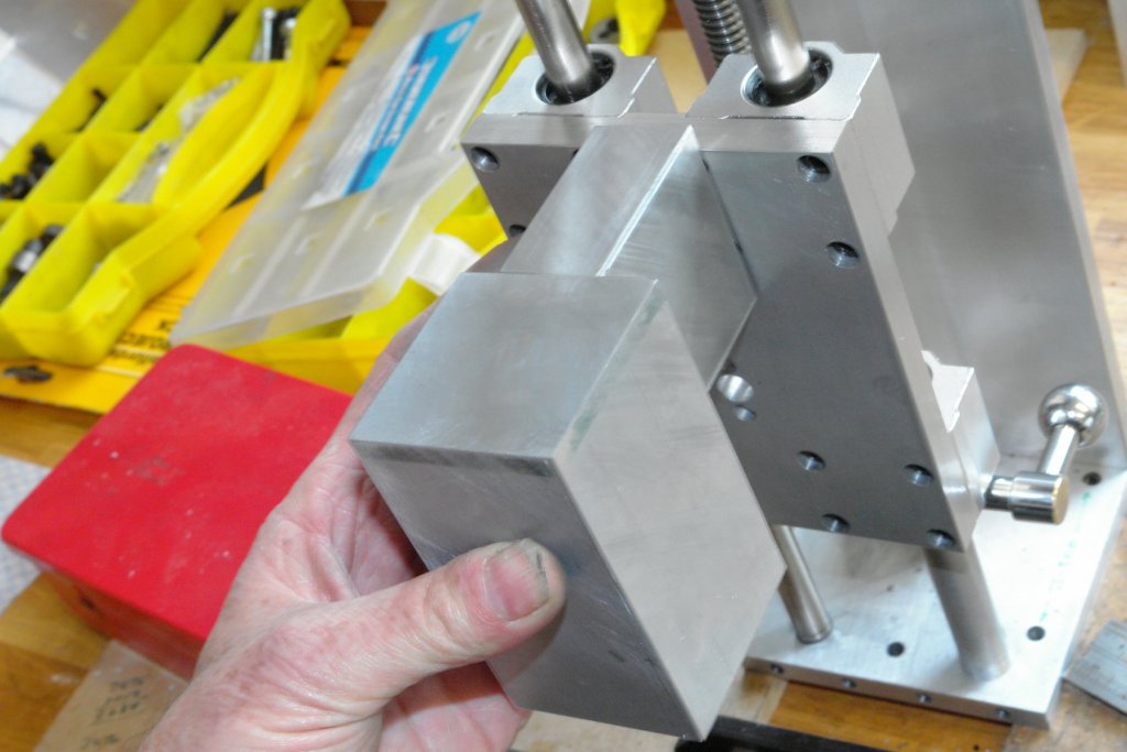
So here goes with a little more progress. The bearing houses stands off the sliding plate by 2 inches. A 2"x2"x1" piece of aluminium was cut from bar and the ends machined square. The bearing housing is drilled and tapped (M8) to take the bolts that will secure it and the stand off to the sliding plate. In the previous photo the bearing housing is held against the mill table by the black clamp while the side clamping is achieved through the bar with 5 horizontal cap bolts. I made this some time back and find it very useful. A recess is cut in the bearing housing to take the stand off. The set up means that the recess is parallel with the axis of the housing. The fit of the stand off into the housing has to be good to make sure that the housing axis is parallel with the stand off. The quality of the fit is illustrated in the next photo where the housing is suspended from the stand off by friction alone. A better view of the joint can be seen in the next photo. I needed bearing retaining plates for either end of the bearing housing, these were cut from 0.1" aluminium plate. The next step was to create the cut out and holes for attaching the stand off to the sliding plate. This was virtually a repeat of the operations to connect the stand off to the bearing housing. And once again I did the friction suspension test to demonstrate the fit. The next photo shows all 3 parts assembled and held together by friction. Thats it for the present. Tomorrow I am going to have a go at machining up the spindle and mounting it in the bearing housing.


- 62 replies
-
- 10
-

-
Tecko I have always found that good quality wine corks are a great source of modelling material. It takes a while to accumulate a decent quantity and the collection process often makes me forget why I was collecting them in the first place. Model is looking like the bees knees.
-
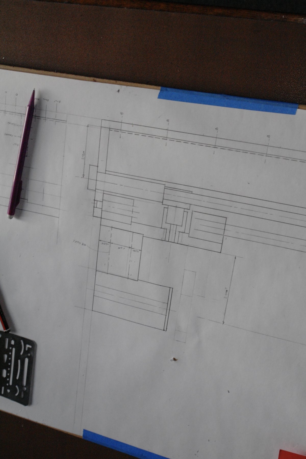
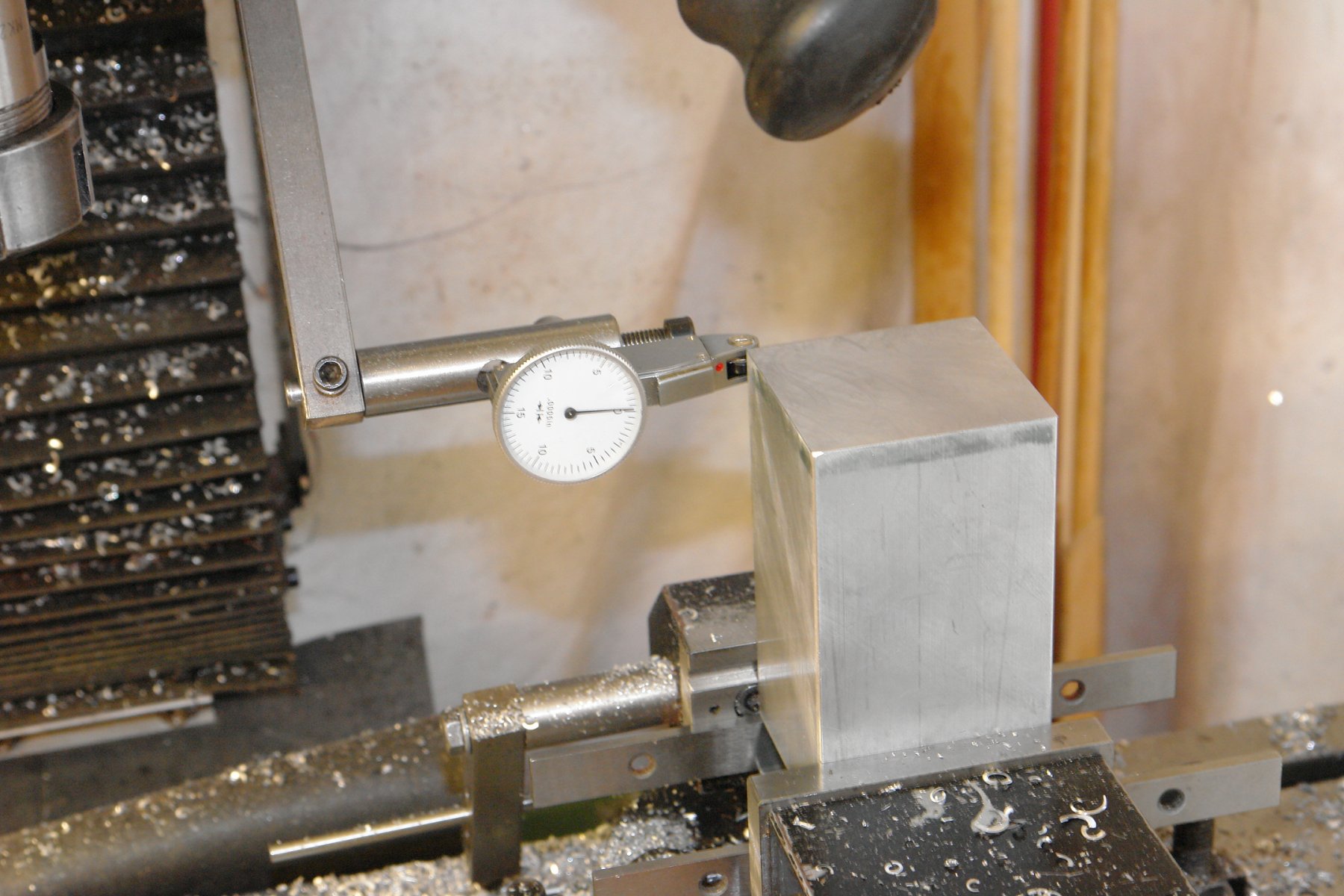
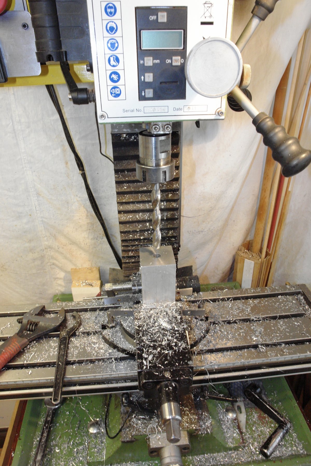
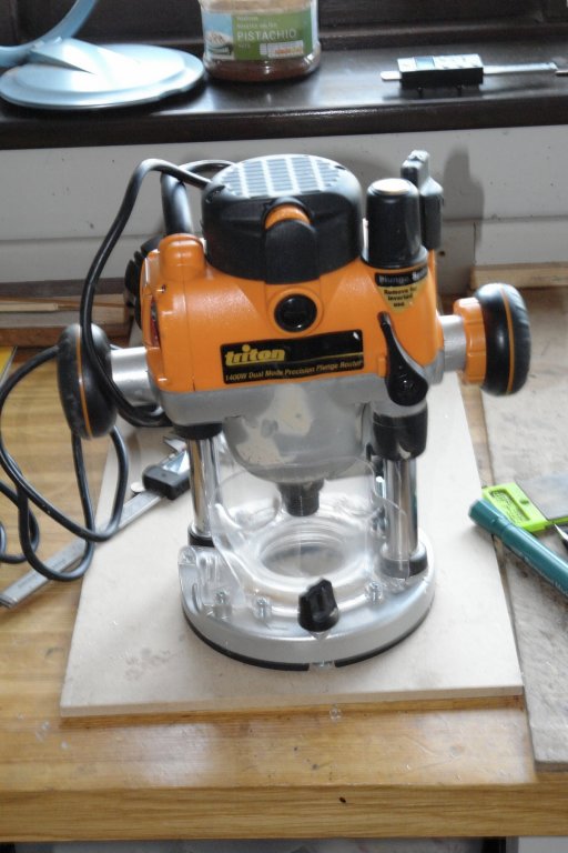
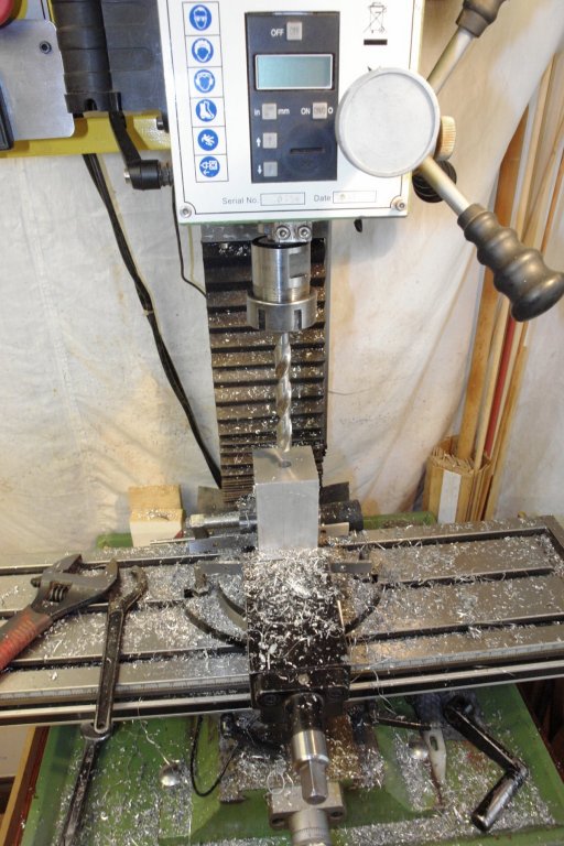
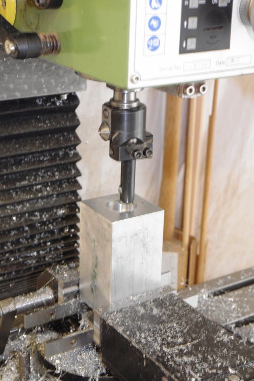
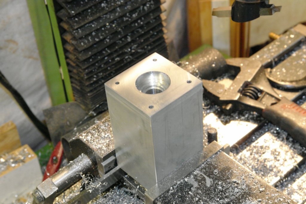
Michael, Druxey, Aviaamator, thank you for looking in and for your supportive comments re my recycling efforts. More to follow:- I finished refurbishing the lead screw, reassembled it and mounted it in the column. I had been giving some thought to the design of the milling head and in particular the type and arrangement of the bearings. Anyway the other night I was lying awake mulling it over when I remembered that I had a broken router in the garage. The router was little used in its first year - probably less than a couple of hours. Early in its second year it developed a winding fault and wouldn't self start. Its was just out of warranty and the cost of repair was nigh on the same as replacing it - so a replacement was bought and it found its way into the rainy day store. The speed and power rating was well in excess of my mini mill requirements and I thought the shaft, bearings and collet chuck would suit my purposes rather well. Stripping down was relatively straightforward and soon the rotor and bearings were out. Removing the rotor winding wasn't easy at all but it was eventual "hacked" off after an hour of sawing. I did a redesign of the milling head after looking at the arrangement of a couple of commercially available mills. I decided to make the bearing housing out of a 2"x2"X3.5" square aluminium bar. I ordered a piece for the purpose - 8 inch long and £13 from fleabay. Chopping off the required length was another hacksaw marathon. The cantilever stem supporting the bearing housing was cut from 2" X 1" aluminium bar from my metal stock. Both items were faced off square using a fly cutter. I love flycutting its so satisfying to see the almost mirror finish appear. Its going to fit together something like this:- There trick to making this work is to machine the bearing housing accurately - so that the shaft runs true. I took a lot of care when mounting the bearing housing in the mill. As bought the bar had a good surface finish and was square and parallel. I used a .0005" graduation dial gauge to check verticality on two adjacent faces. A lot of tapping with a hammer and checking and rechecking using the dial indicator finally got both vertical faces to within .0005" over the 3.5 inch length. I drilled through the 3.5" length of the bar to take the shaft. A bit of a heavy job for my mill which complained quite a lot. This operation wasn't helped by my smaller twist drills being somewhat shorter than the hole being drilled. However eventually I got through. I then had the job of opening out the ends to take the bearings. The bearings needed to be a very good fit so I took it real slow using my boring head - that is the head in the picture and not the head on my shoulders. Having done one end I flipped the bearing housing over and went through the whole laborious process with the dial gauge once again. This time it took even longer - probably about an hour (although my wife tells me time is distorted in the black hole of my workshop). Each end has 4 holes which will take a plate that clamps on to the outer race of the bearings. I managed to get the bearings nicely fitted with no slop. I need to give a bit more thought to the arrangement of the belt drive - maybe in the early hours of tonight.


-
Hello Barbara, a very touching and inspirational introduction, your father is a very lucky man to have you as his daughter.
-
Thank you Paul - Both look interesting - particularly exotichardwoods.
-
Paul, Where do you get your boxwood from please? And where did the ebony come from?
-
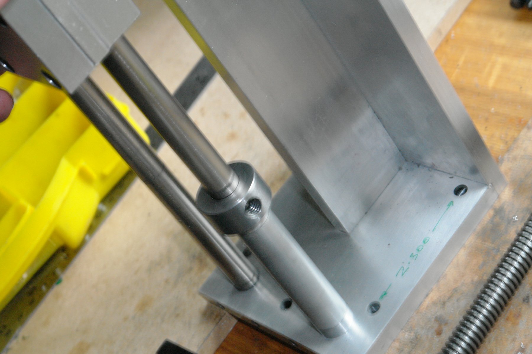
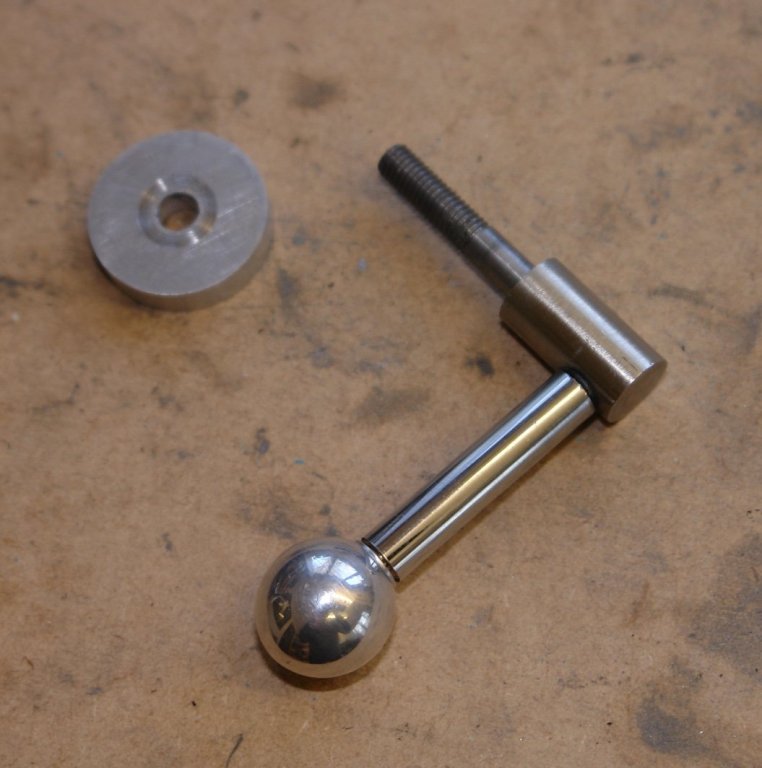
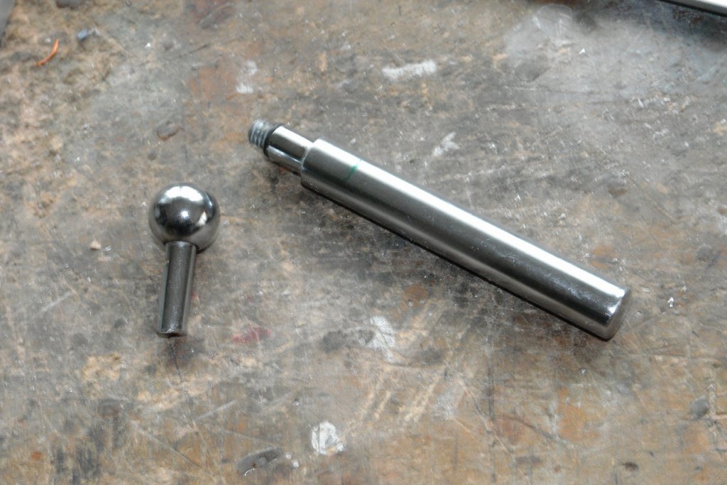
Mark - given your comment you may find the moveable end stop interesting. A couple of months ago I refurbished the daughters bathroom and amongst other things recovered the following:- The bar is the handle from a mixer tap and the ball with shaft is the end of a wall mounted toilet roll holder. I made a clamping ring from 1" bar - bored to have a close fit on the runners and drilled and tapped to take the end of the mixer tap handle (M8). The ball shaft was threaded and the handle was bored and tapped to take it. The end of the handle was removed and returned to the rainy day bin. Recycling can be very satisfying.

-
Fantastic models Marijn.. I'm sure you will make a very valuable contribution to MSW.