KeithAug
-
Posts
3,986 -
Joined
-
Last visited
Content Type
Profiles
Forums
Gallery
Events
Everything posted by KeithAug
-
 Dan I am only as far as November 6th but by the rate you are progressing I need to get a move on lest you finish it before I catch up. A fascinating build. I found it interesting / surprising how much photographic evidence you found given the era she inhabited. A great project which I look forward to following.
- 238 replies
-
- 4
-

-
- leviathan
- troop ship
- (and 2 more)
-
Hi Dan One of the high priorities on my catch up list was to see how Michelangelo turned out. I have to say she is beautiful and only bettered by you detailed log of the build, very well done. I'm now heading off to have a look at Leviathan.
- 287 replies
-
- 2
-
-
- michelangelo
- ocean liner
- (and 1 more)
-
Patrick. I just enjoyed catching up. She is a weird vessel, however as usual, your ability to work the detail at this scale is most impressive.
-
ancre La Salamandre by tadheus - 1:24
KeithAug replied to tadheus's topic in - Build logs for subjects built 1751 - 1800
Happy new year Pawel. Hope you are keeping well. Lovely gun. -
Mark - Looking good-----steady as she goes. Try splicing the mainbrace - I always find it makes things look even better.
-
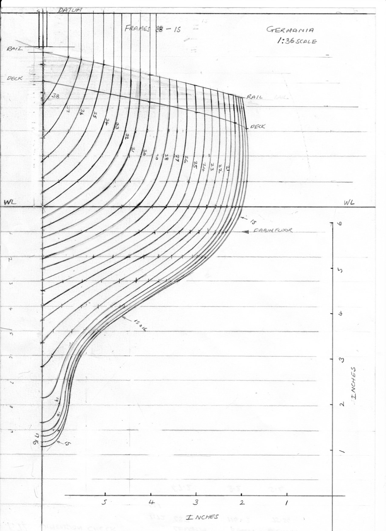
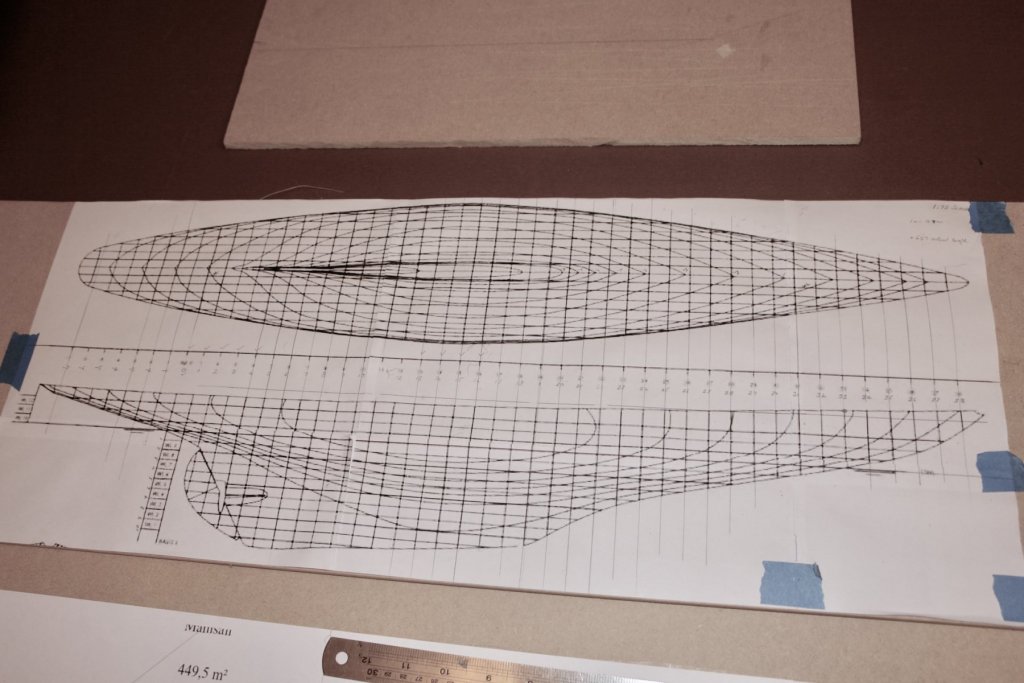
Just a bit more draughting progress. I finished the forward section frames - 15 through 38. I was pleased with the result although these are the most easily defined frames because the are reasonably well spaced and don't conflict with one another. I also marked the waterline, deck edge lines and the rail lines on the sections. Additionally I have included the upstand and datum line that will be used later for mounting the frames (inverted) on the building board. The slot in the up-stand will form a cut out to align the frame centre line on the building board - this will come clearer later. I have included below the PDF file of these frames for downloading. I have also put x and y scales on the PDF to allow scaling when printing. I found that in my case the scanned PDF came out at 93% full size and I had to adjust the size in the print programme back to 100%. I checked the printed scales measured 6 inch as original drawn as a check on the reproduction accuracy. Schooner 1.pdf

-
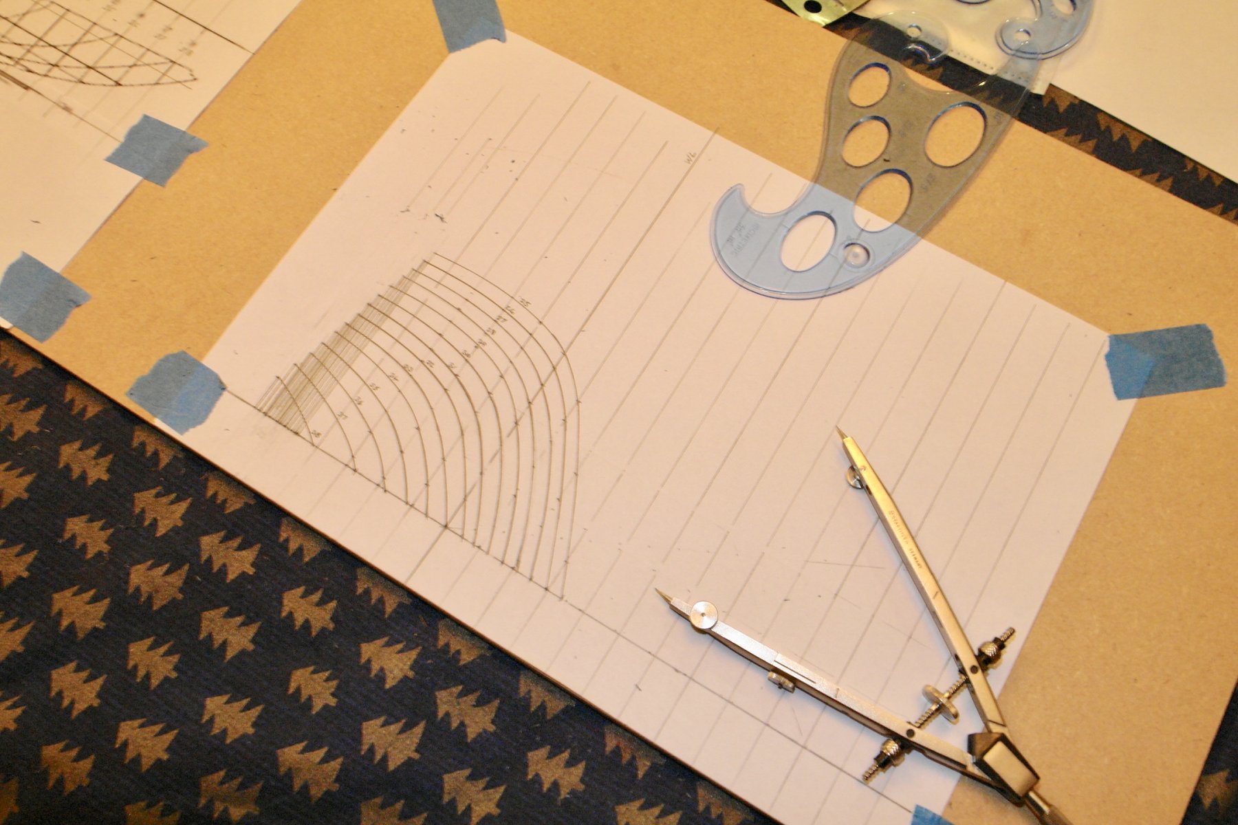
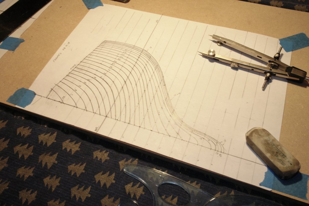
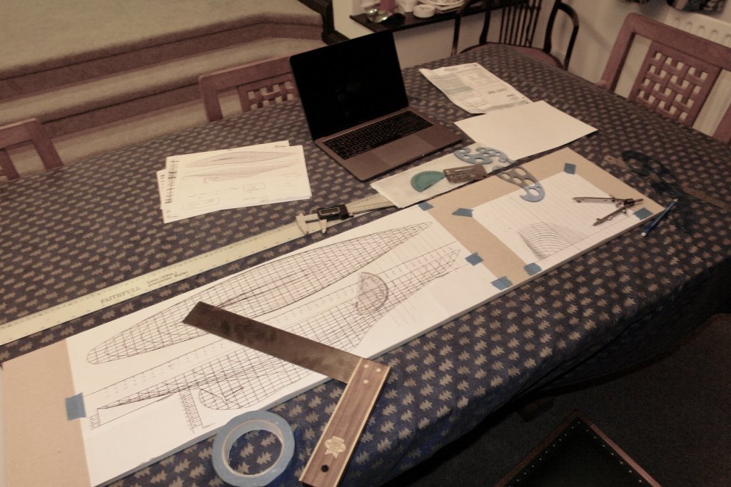
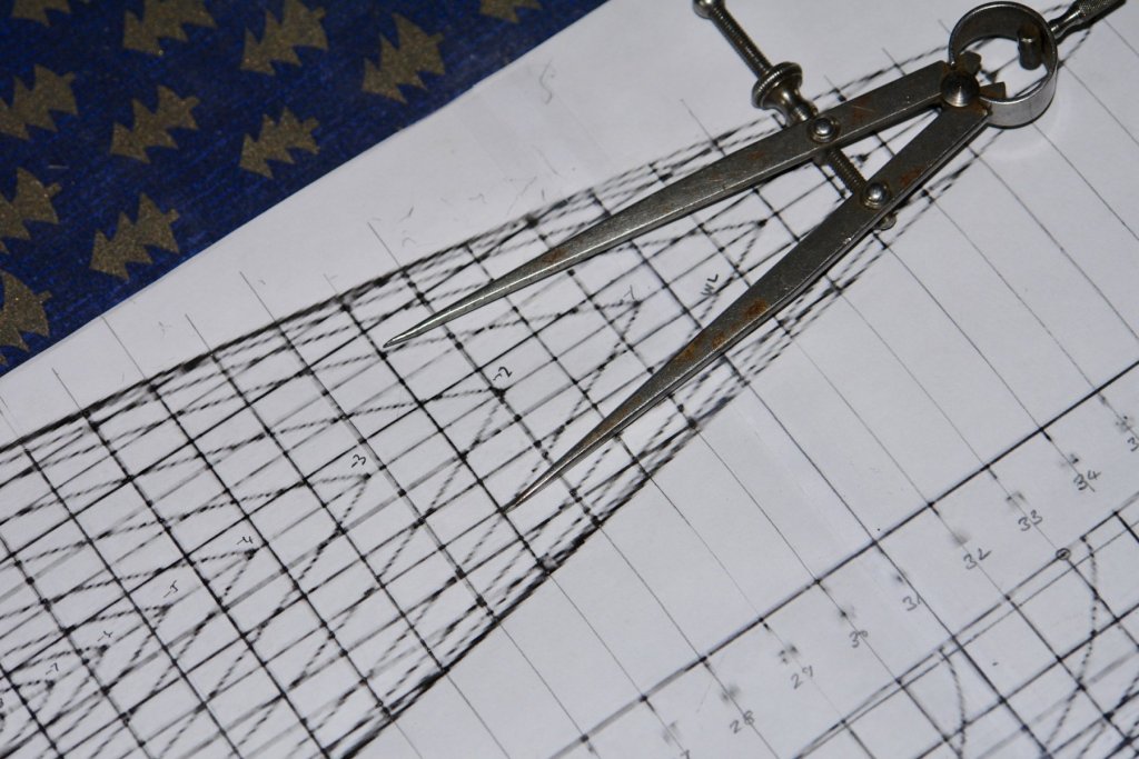
I started plotting the frame section lines. The drawing numbers the frames with frame 0 at the steering position. Frames 1 to 38 are forward of the steering position and frames -1 to -7 aft of it. It's a bit slow going but I am making progress. I have commandeered the dining room table - somewhat warmer than the workshop at present and my wife can find me more easily. The Christmas table cloth hasn't been removed yet. My draughting arrangements are somewhat basic, MDF for drawing board, my woodworkers square, dividers, french curves and a much overused eraser. Oh! and a laptop to give the impression of sophistication. Never the less it seems to work and the bow sections are coming out well. I will publish PDF's of the sections in a later post. .

-
Richard I emailed the builder but didn't get a reply - probably a victim of their spam filters. I not too worried as I think I will get a decent result from the image I have. The instruments are Staedtler. The large compass has a nifty collet arrangement on the adjustment screw to give fast action as well as fine adjustment.

-
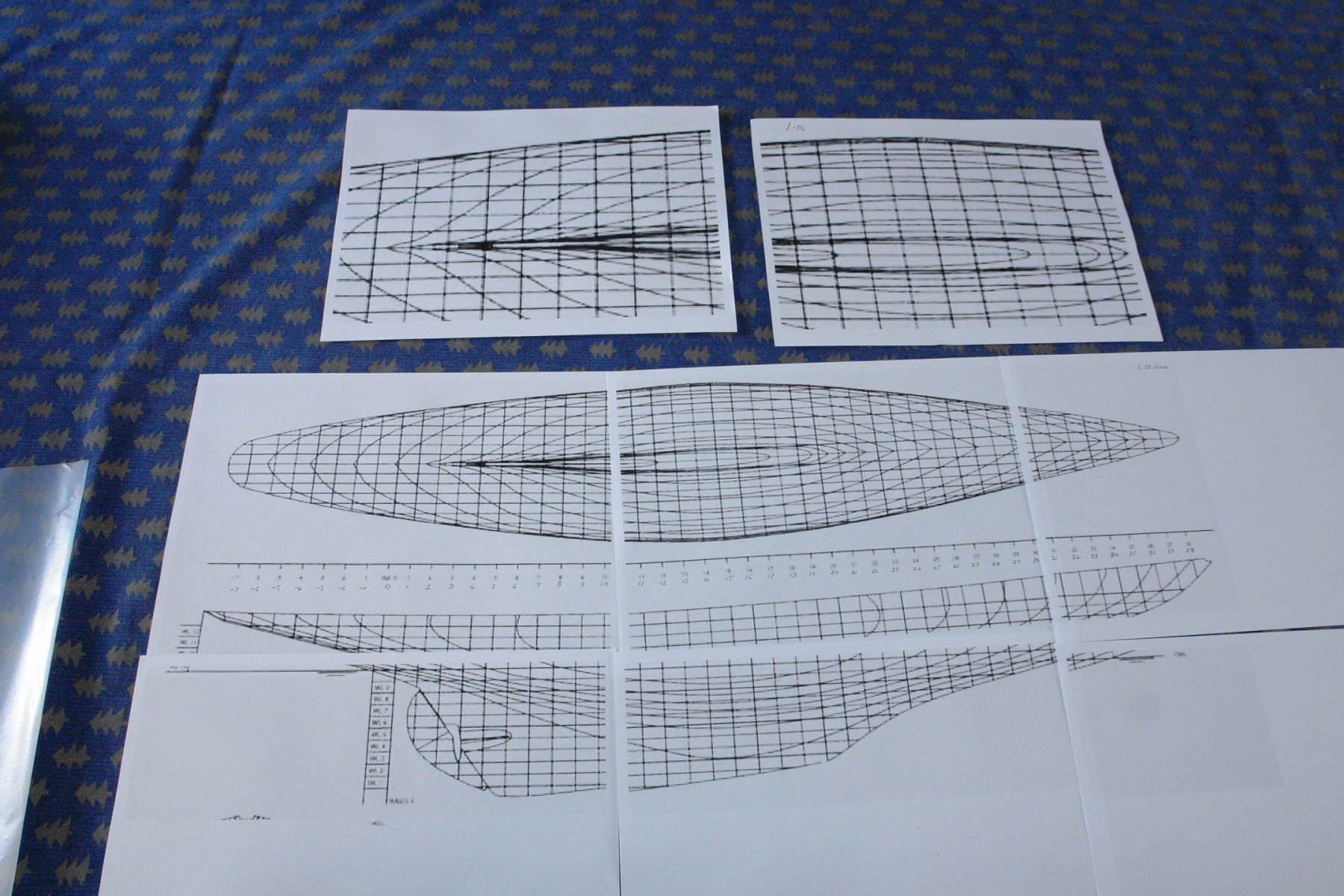
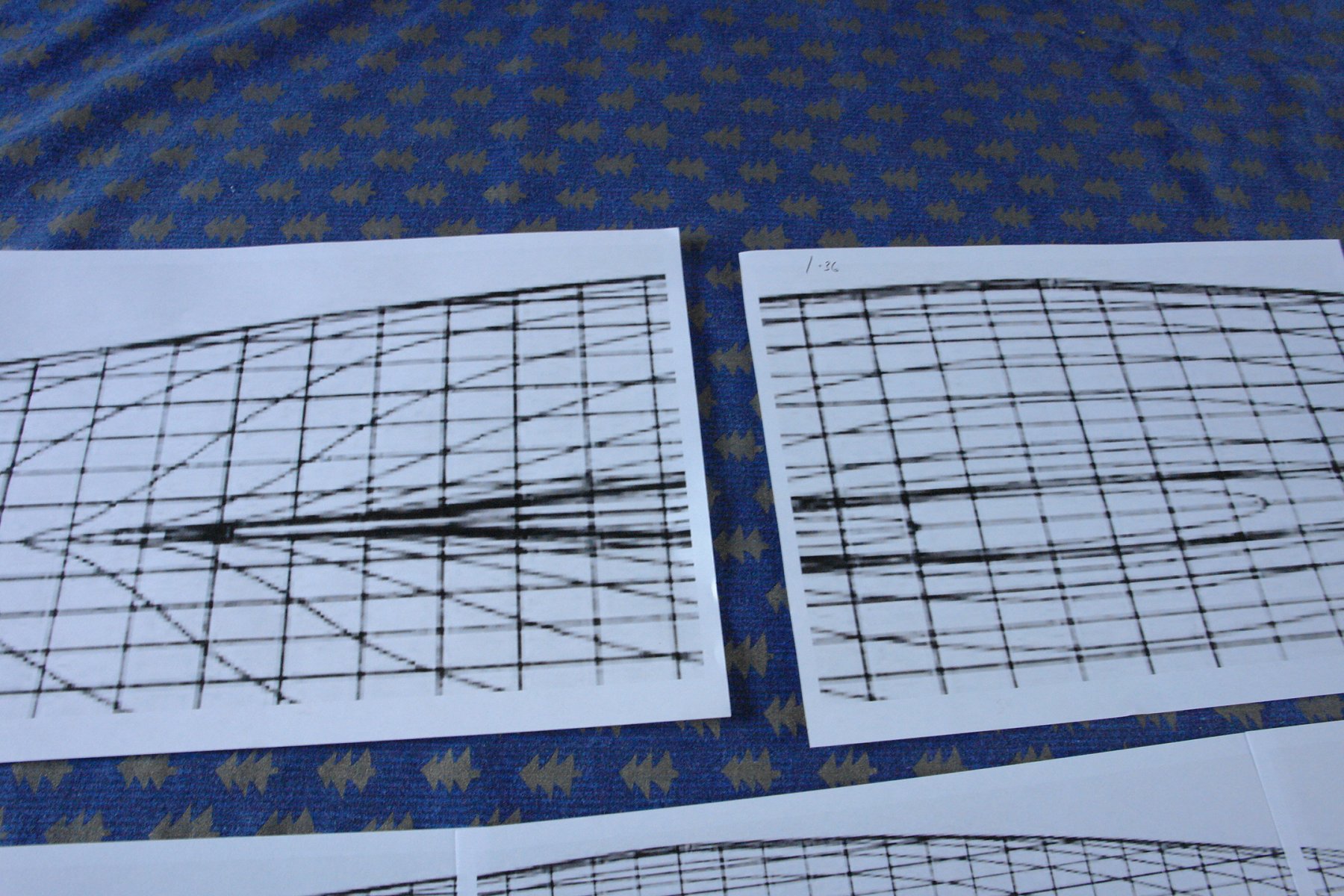
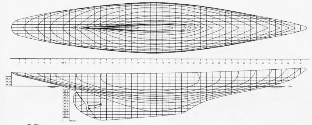
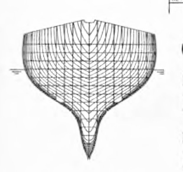
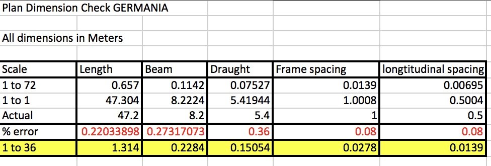
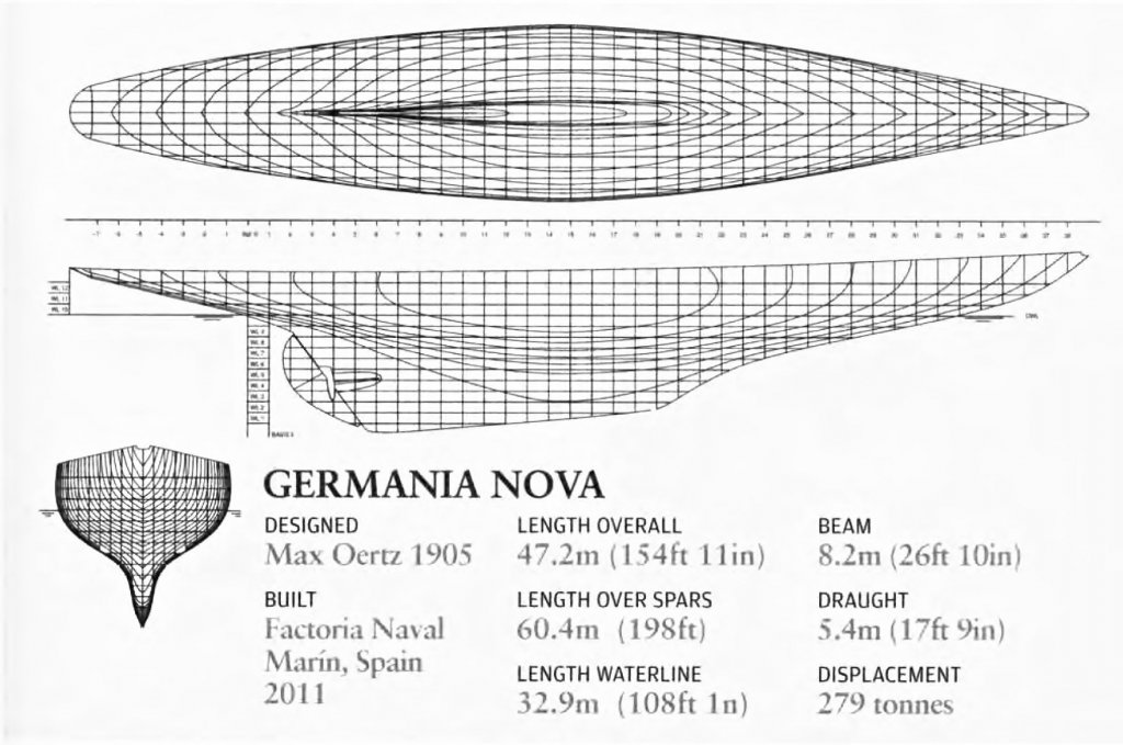
I have made a start on defining the frames I started with the small web image. This was originally in a magazine and probably scaled about 6 inches long. I had a play with it in the Mac iPhoto package basically whitening and sharpening the image. The plan and side elevations improved more than the image showing the frames. This wasn't a big deal as the frames were only for the fore part of the yacht and anyway I thought plotting the frames from the plan / elevation was likely to be more interesting. I printed the plan / side elevations at 1:36 and 1:72 scale. 1:36 is the upper 2 sheets in the next photo, the lower 6 sheets are 1:72. Scaling up to 1:36 produced rather wide / poorly defined lines. 1:72 was somewhat better. As I was going to draw the frames at 1:36 the scale of 1:72 worked well as I could measure across the matching plan section lines and use this dimension as the centre line to hull dimension on the 1:36 frame sections. I felt the urge to check that the plans were reasonably accurate as I was worried that length / beam scales could have been distorted. Hence the following check calculations:- The error line (red) shows the maximum error to be about a third of a percent which I am happy with. It is probably worth stating that the frame section lines are spaced at 1 meter (full size) or circa 1.1 Inch at 1:36. For building I had to consider how many frames to create. 1.1 inch spacing gives 46 frames and of course 2.2 inch gives 23. I decided to go with the larger number.


-
Aviaamator Yes - that's how I do it and I also brake off the pins at the neck - usually when tapping them with a pin hammer?
-
I will be interested to see how you get on with shaping the sail Mark. I have tried suspending a horizontal frame, attaching fine cotton cloth at the edges and wetting with dilute PVA. The result never seemed to be stiff enough to counter the stresses induced by rigging. I did lay up some cloth once with 2 part epoxy mixed and then painted on (used to repair a radio control car body). This was wonderfully stiff but i did need the car body as a former to lay it up on. I was thinking about moulds for forming snails a while ago and came up with a plan to create a frame the shape of the sail and then tacking styrene sheet on to it. Then with the frame horizontal softening the styrene by pouring boiling water on it. hopefully once the belly starts to form the "bowl" will collect the boiling water and add to the shaping effect. I haven't however tried it yet so it may be a rubbish plan.
-
Valeriy, I have always found the transitional warships of the pre-dreadnought era to be most interesting. if you don't mind I will follow along with great interest.
-
John, Yes, as dinghy's go it is quite spacious. No I don't have that book, I have had a quick look on the net and it does look interesting. I think I will add it to my birthday list, or buy it sooner if I find a good deal. I do have a very tatty copy of The Gaff Rig handbook by John Leather which I find very useful from time to time.
-
Chris, Michael, Paul, Dan, Richard and GL. Thank you all for your comments - its good being back among friends. Richard - metric is fine but I am an old Imperialist at heart. I just love the way that 3ft becomes an inch, it avoids much use of the calculator when making parts. In fact I'm even trying to convince my daughter-in-law of the merits of £sd (pounds shillings and pence). Although she has a Phd she just doesn't get it.. Kids these days just want an easy life!!!!! Chris - Sometimes I miss the last boat too (often - according to the wife). Dan - Hoping I wont need the optiVISOR for this one. Michael - You seem to have had news about my Knighthood before me? Paul - Thanks for the wood supplier advice.
-
I have just started catching up Paul. Nice progress and some interesting build techniques. I think it will take a while to digest it all. Where do you get your exhotic wood please?
-
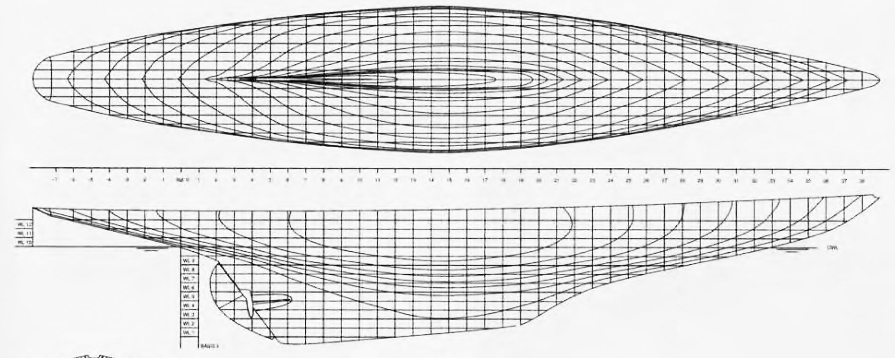
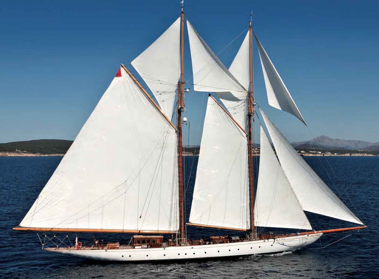
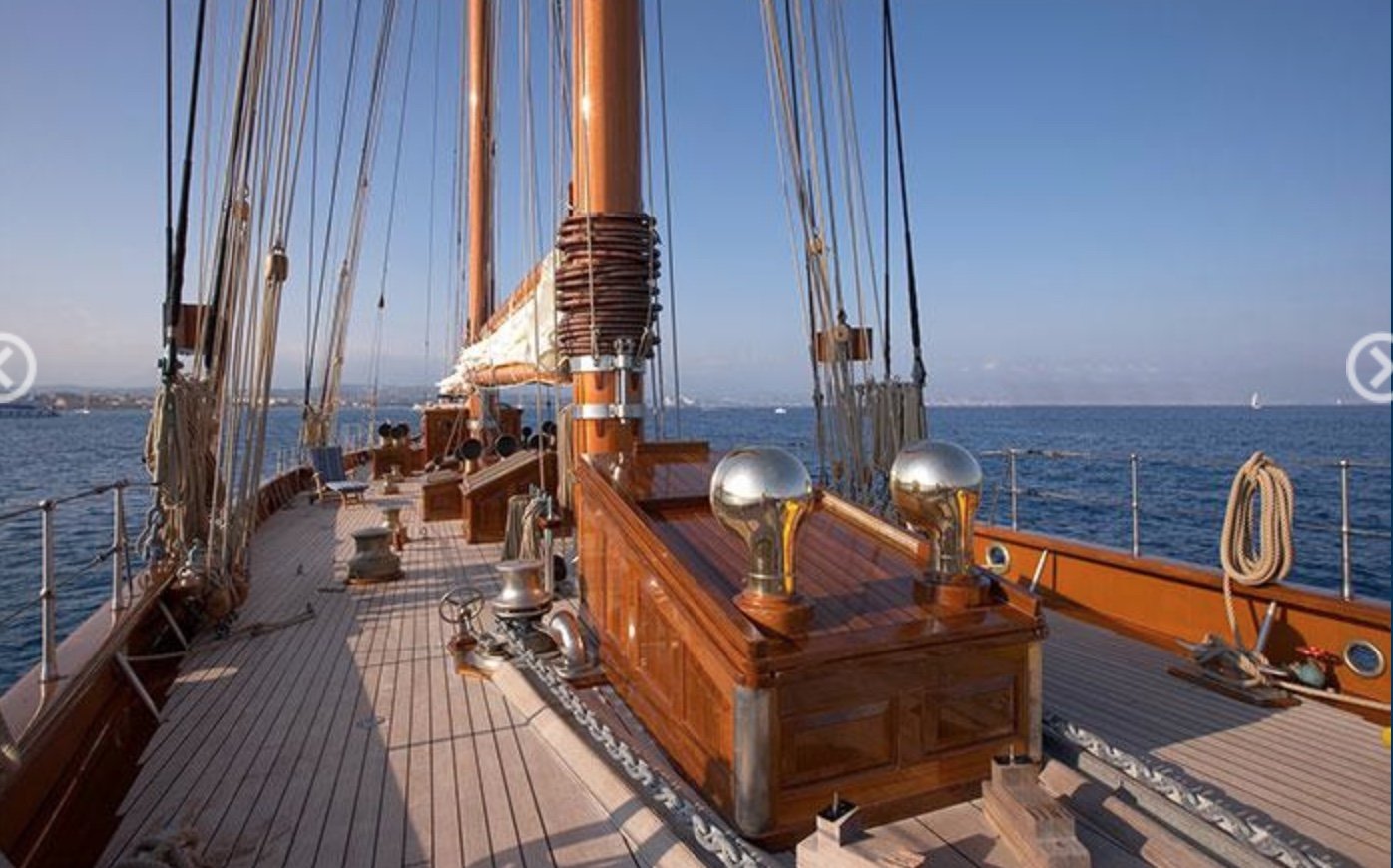
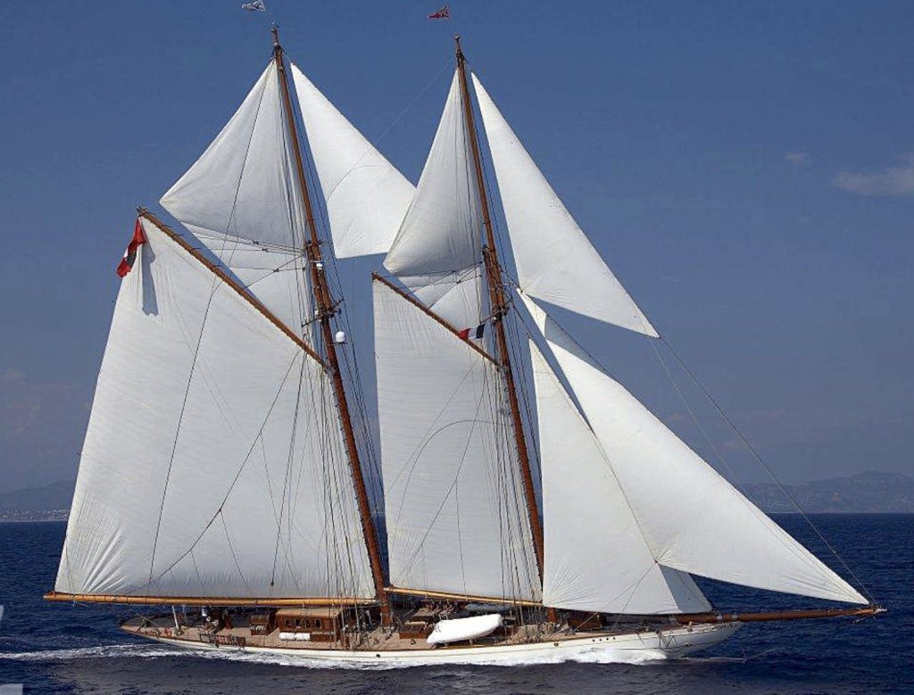
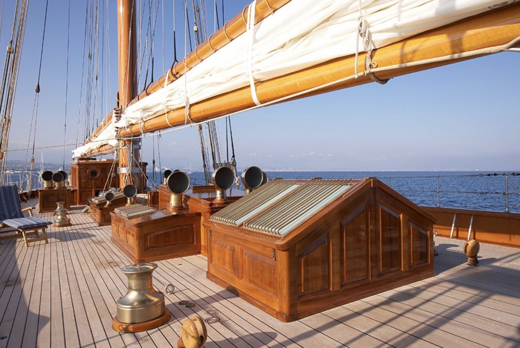
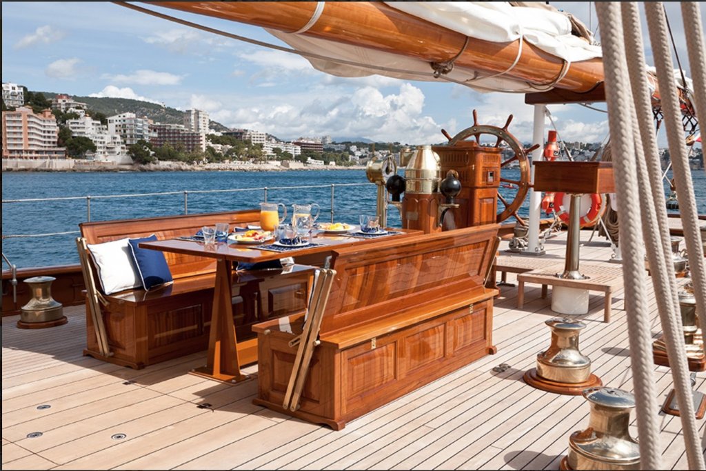
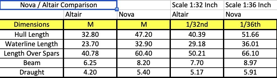
I have neglected ship modelling for too long and my New Years resolution is to get started on a new build. So here we go. I wanted to build another classic early 20th century schooner but found sourcing decent plans very difficult. This in part was the reason for not starting a build earlier. After many hours spent on the web I decided I could get together enough information to build a decent representation of Germania (either in her original form or as the recently built reproduction). So Germania sort of chose me rather than me choosing her. Because I found getting early 20th century plans so difficult I though would document (through this log) enough information for others to build her should they so wish. So I will include PDF files and dimensioned sketches as I go. And so to a bit of background:- The first Germania (designed by Max Oertz in 1905) was conceived as a racing yacht and built for Dr Gustav Krupp von Bohlen und Halbach, a German businessman and industrialist who used her to promote his steel business among the social elite. In her first year she won Cowes Week with a new course record and often raced against Kaiser Wilhelm’s Meteor IV, although, rather diplomatically, that was one yacht Germania never beat. In one year alone, she won more than half of the regattas she entered and her winning streak only came to an end due the outbreak of World War I. Seized as a prize of war, she was sold on several times, ending her days in the US. In 1930 she foundered in a storm off Key Biscayne; she now forms Florida’s Seventh State Underwater Archaeological Preserve. Germania Nova is 60 metre gaff-rigged schooner : a replica of the classic 1908 Germania, using the same hull lines, deck- and sail-plans. She was built as a super yacht by Factoria Naval Marina in 2011. The two yachts look identical with the exception of modern electronic / navigation equipment. Fortunately a lot of photos are available which I will insert in the build as I go. Here is a taster:- Plenty of opportunity here for nice wood and metalwork. This has the potential to be a big model. I like larger scales and in choosing a scale I was minded to do a comparison with Altair (previous build). Hence the following chart:- I'd really like to build at the same scale as Altair but I don't think the house controller would put up with it. So 1:36 it is. It is still however some 16 inch (30%) longer than Altair. I will enter sizing negotiations once it is too late to change. I won't be cutting wood for some time as the next image is the best I can do for hull lines. It does not look too bad at this scale but when blown up the lines lack definition. It will take some effort to convert this into cutting templates for frames. So I now need to find my drawing implements - bought for my first post apprenticeship job in the Rolls Royce Design Office in 1975.


-
Happy new year John. I had a break from ship building so missed your trials and tribulations. Im very pleased you came through it all. my very best wishes.
-
Michael - I hadn't looked for a while - so much to catch up on. Very interesting techniques and everything up to the usual extremely high standard.
-
I just spent a happy hour catching up. Really beautiful work - well done.
-
Moab / Mike Thank you very much for you kind comments.
-
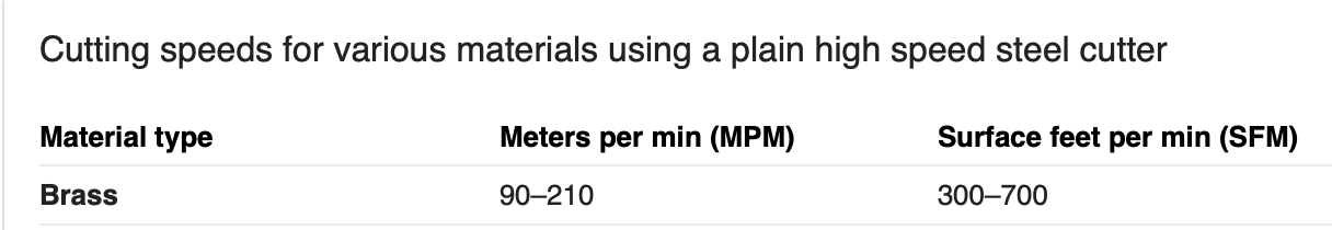
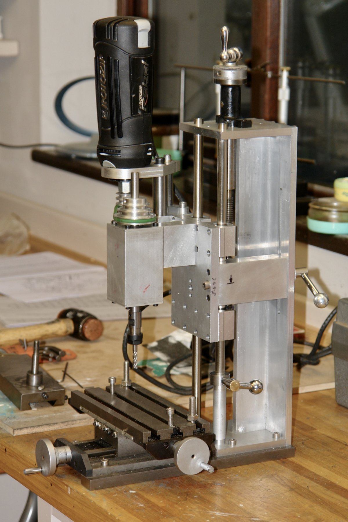
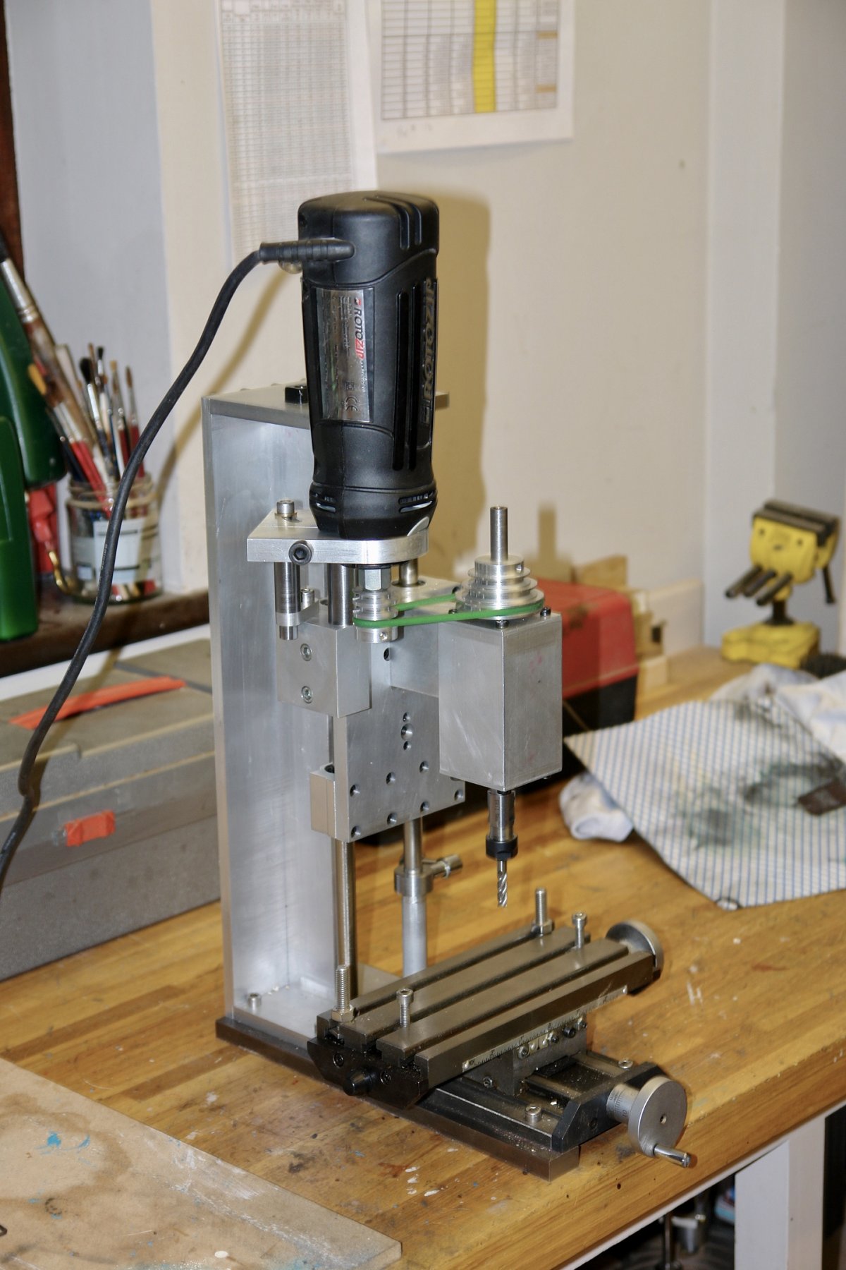
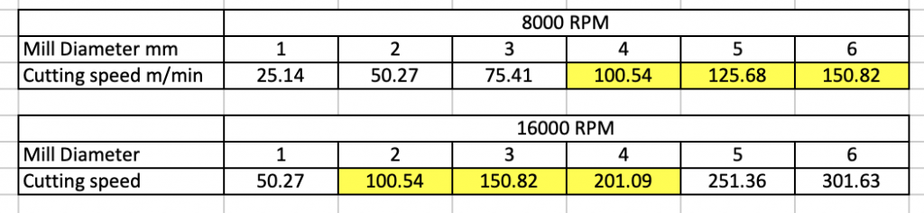
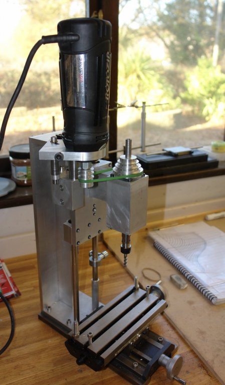
Mark / Wefalck Thank you for your interest and observations. One of the reasons for building the mill was to get higher speeds than available from my larger mill. The recommended speed for machining brass is 90 to 210 meters per minute:- The maximum size of cutter I plan to run in the mill is 6mm. The pulley ratios give me 8000 rpm, 12000 rpm and 16000 rpm respectively. Calculating cutting speeds for 8000 and 16000 rpm gives the following results:- The cells highlighted in yellow are all within the recommended range. You can see that even at the higher speed I still don't achieve the recommended cutter speed for a 1mm diameter cutter. At the lower speed only the 4mm, 5mm and 6mm cutters come within the recommended range. Of course for hardwoods much higher speeds are recommended. I expect to use the mill almost entirely for soft metals and hardwoods. The bearing speed rating is important. I scavenged the bearings from an almost new (but dead) Triton router which ran up to speeds of 16000 rpm. Fortunately I am working within this speed range.

-
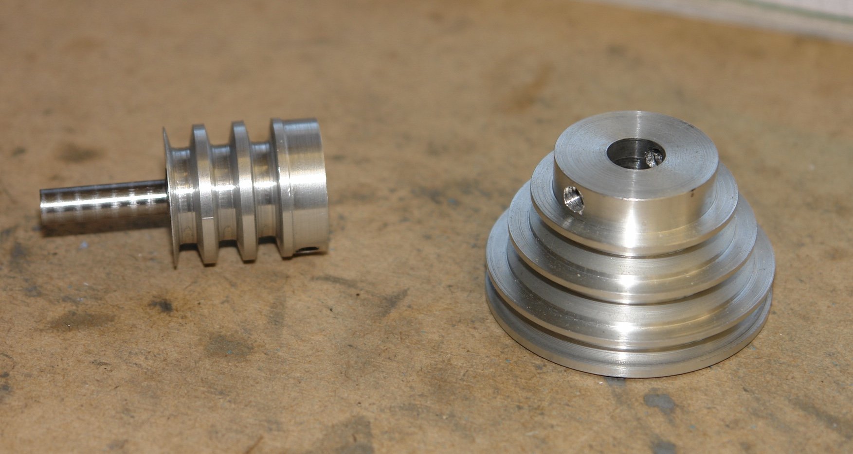
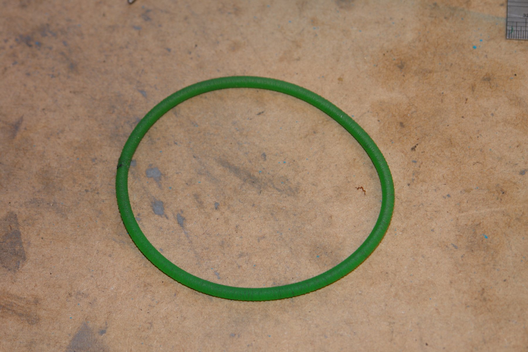
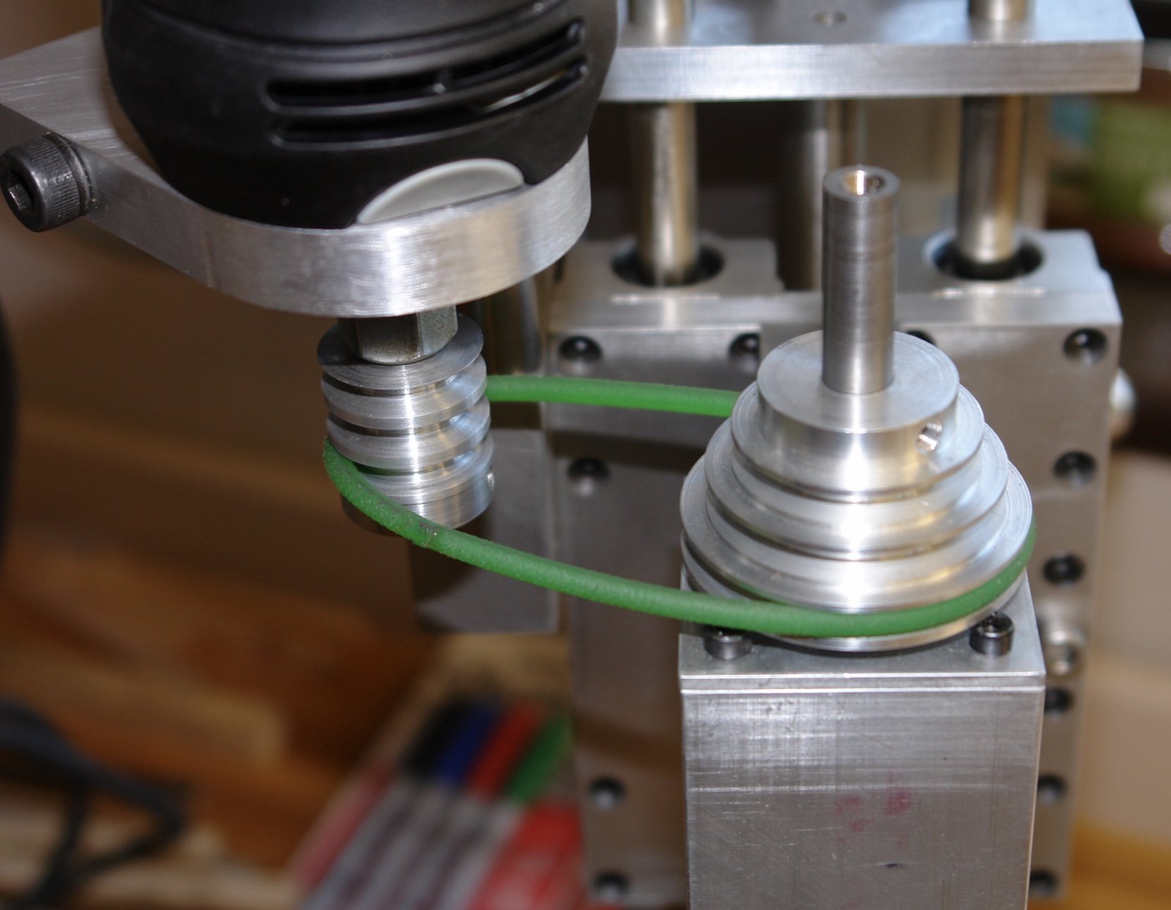
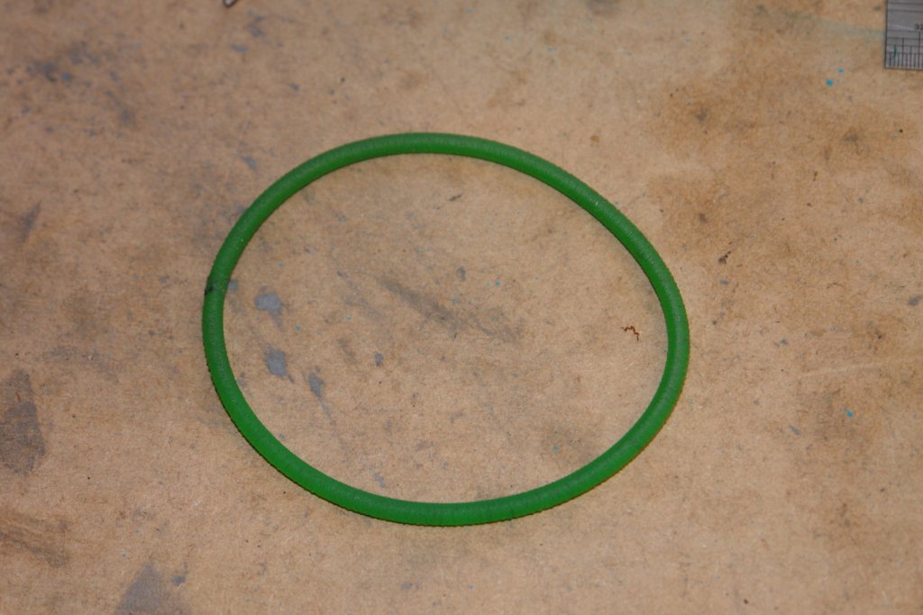
I made the drive pulleys out of aluminium. In the end the sizes were dictated by the stock that I had to hand (which was a bit on the small size for the larger pulley). The grooves are sized so that the belt binds on the side of the groove rather than the bottom as this improves power transmission. The wedge angle I used was 30 degrees. The 3 pulleys give 3 different speeds, the minimum speed being 8000 rpm - a 3 to 1 reduction from the 24000 rpm lower speed of the drive. The boss was drilled and tapped to take grub screws. These fit into dimples in the shafts. the belt was made from watchmakers lathe drive belt of 4mm diameter circular cross section. The belt comes in 3m lengths and the required size of belt is cut and the ends heat welded together. The pulleys were mounted and the belt was installed and tightened using the adjuster previously described. And that is it. I have run it and done a couple of cuts and it seems to work fine. I really need to get on with another ship build to test it in anger. In retrospect i decided I didn't need DRO.


- 62 replies
-
- 11
-
-
How would you improve your Byrnes tools?
KeithAug replied to Keith_W's topic in Modeling tools and Workshop Equipment
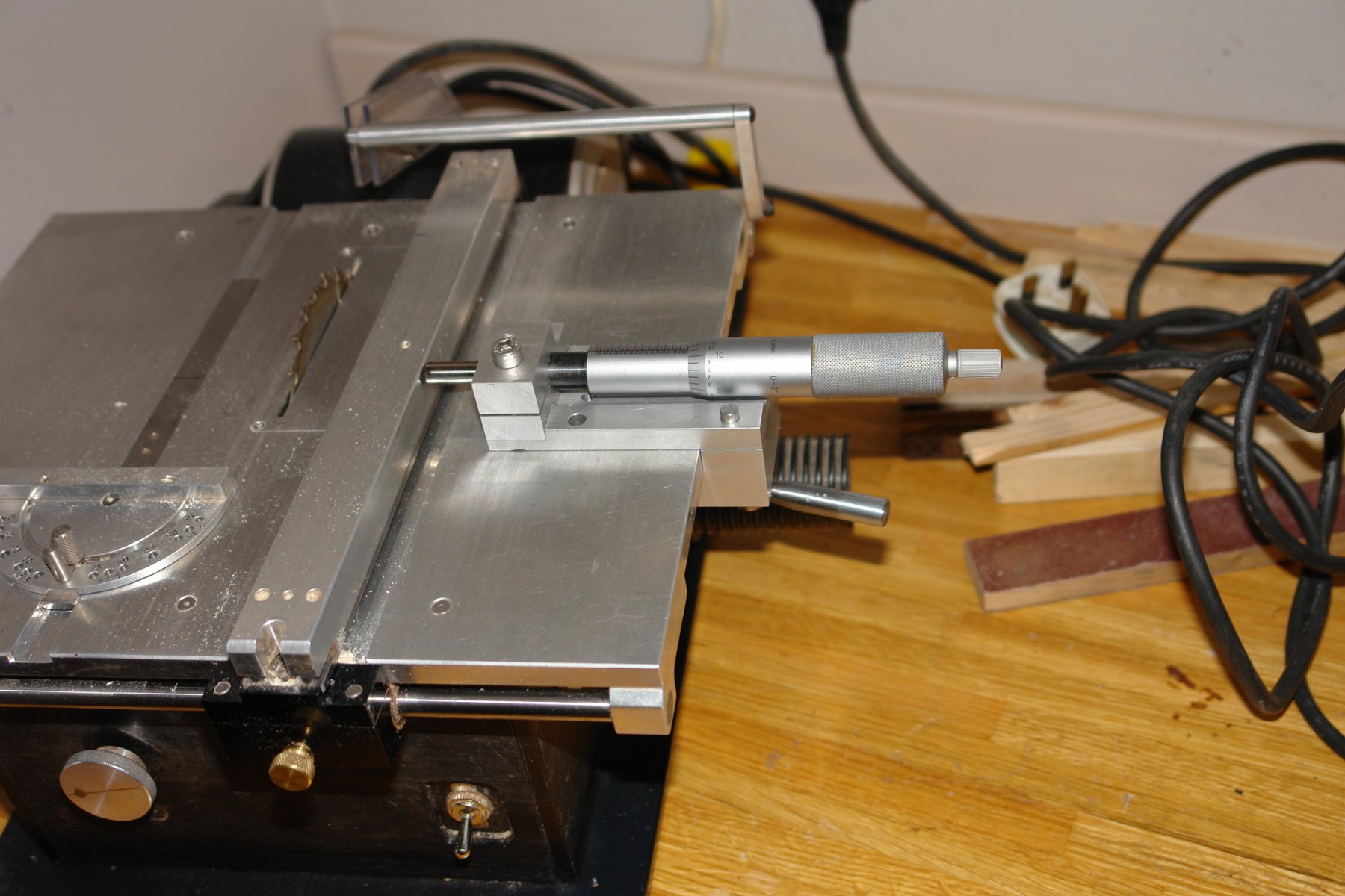
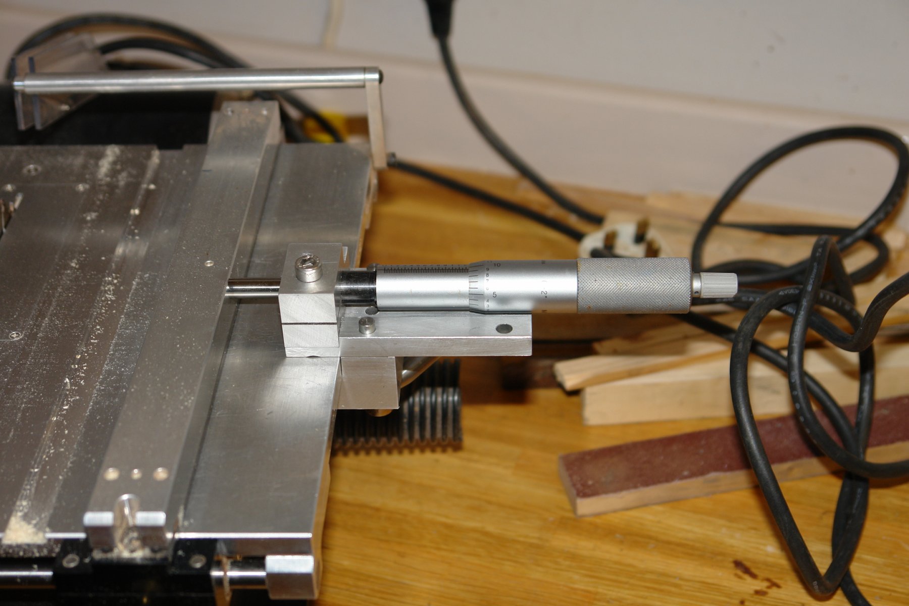
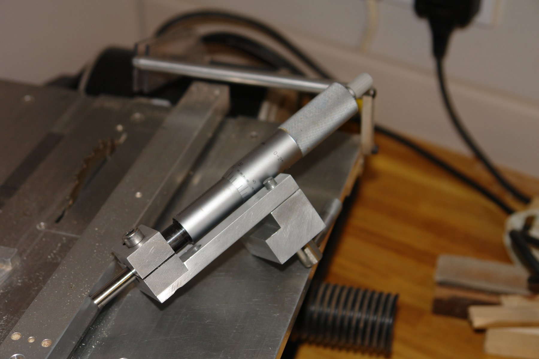
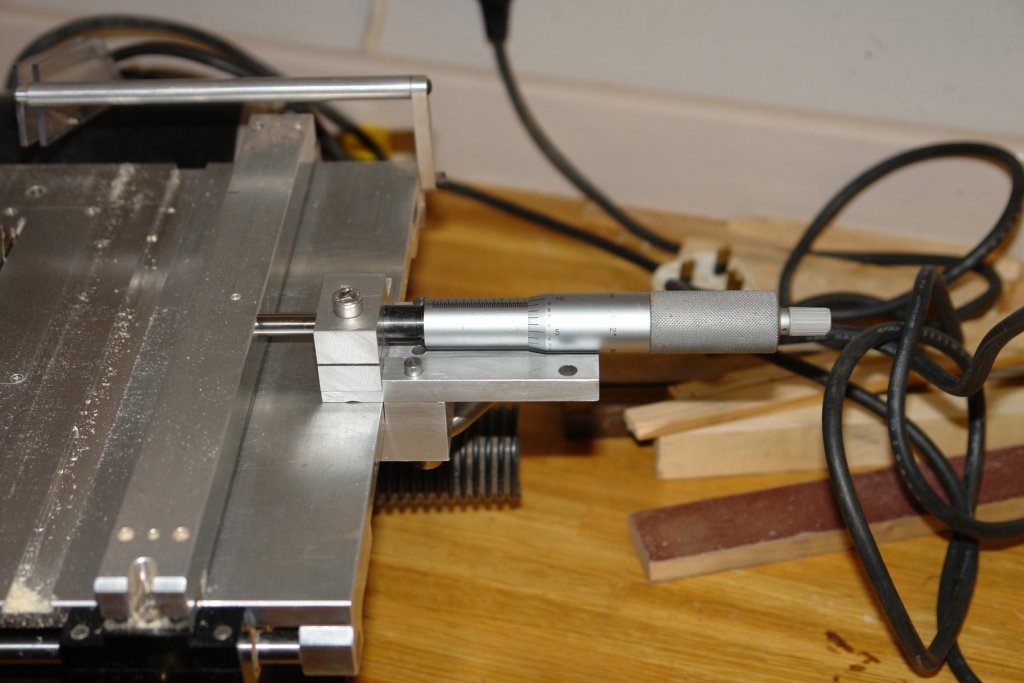
I use the micrometer attachment on the Byrnes saw extensively, however I find three aspects of it a bit frustrating. Firstly and probably the most frustrating aspect is that I find I often want to accurately cut widths (or a series of parallel slots) greater than 1/2 inch. To do this I move the fence and micrometer in series of steps, this is time consuming and (unless carefully done) introduces errors. Secondly I sometimes need the full travel of the fence and have to remove the micrometer to achieve this. Removal and replacement can be a bit time consuming. Finally my eyes are not as good as they once were and I sometimes struggle to read the small 1/2" micrometer body. I would have put up with these minor annoyances had my brother in law not donated a 2" travel Mitutoyo micrometer body recovered from one of his engineering projects. I mounted this on a quick release clamp which attaches to the edge of the table. This gives me 2 inches of fence travel before I have to reset the micrometer to its second clamp position. the clamp is designed so that the second position is exactly 2 inches further out than the first position. This means I can get the 2" to 4" range by simply moving the clamp. Removal and replacement of the micrometer is now very quick and tool free. The larger micrometer body makes reading far easier.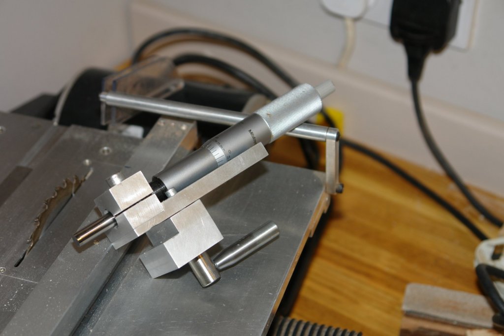


-
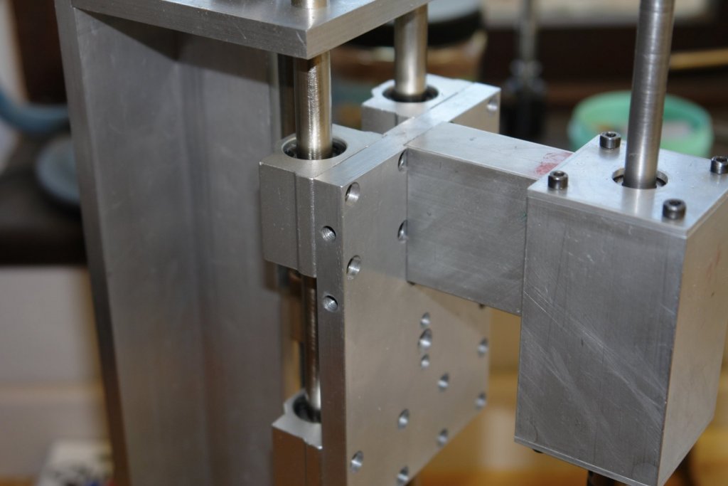
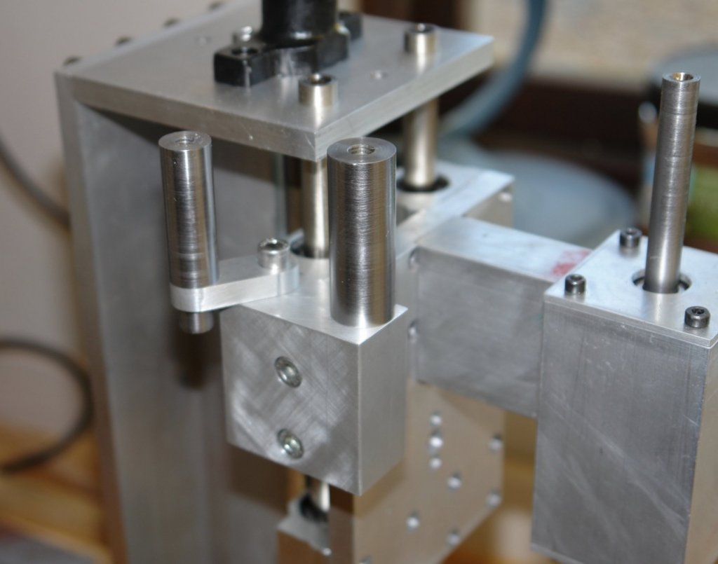
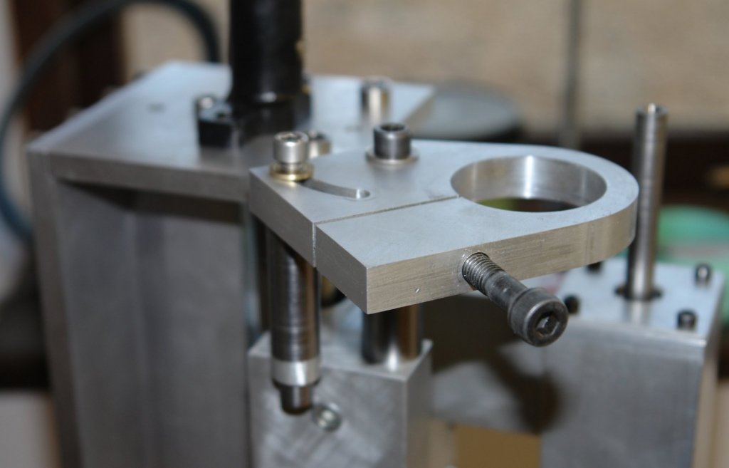
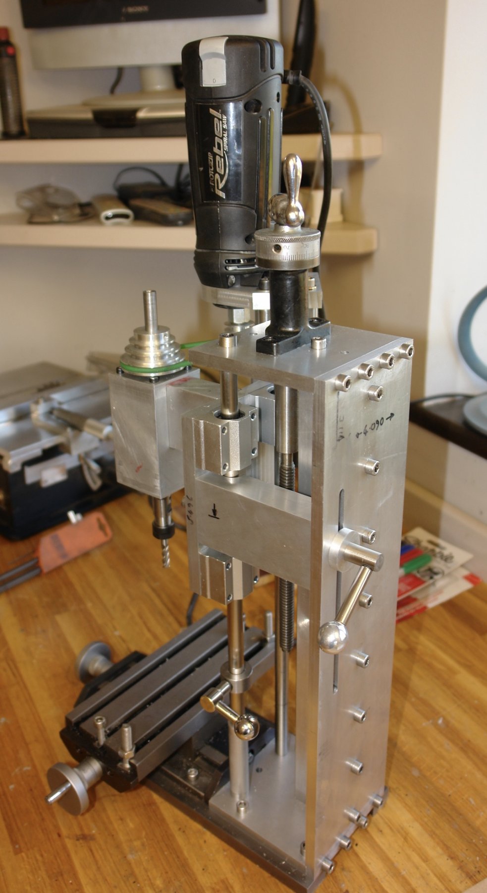
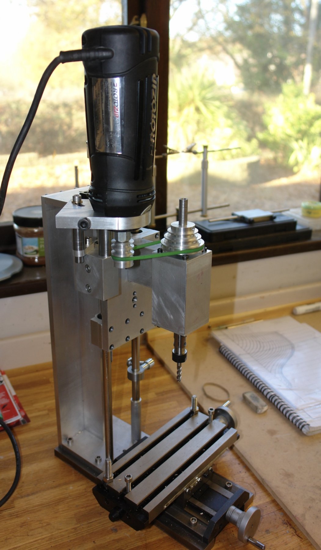
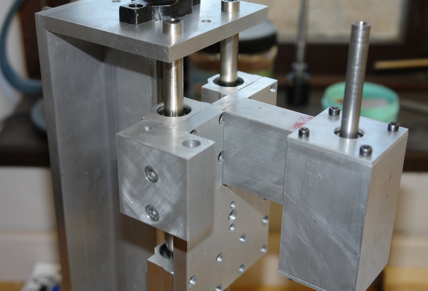
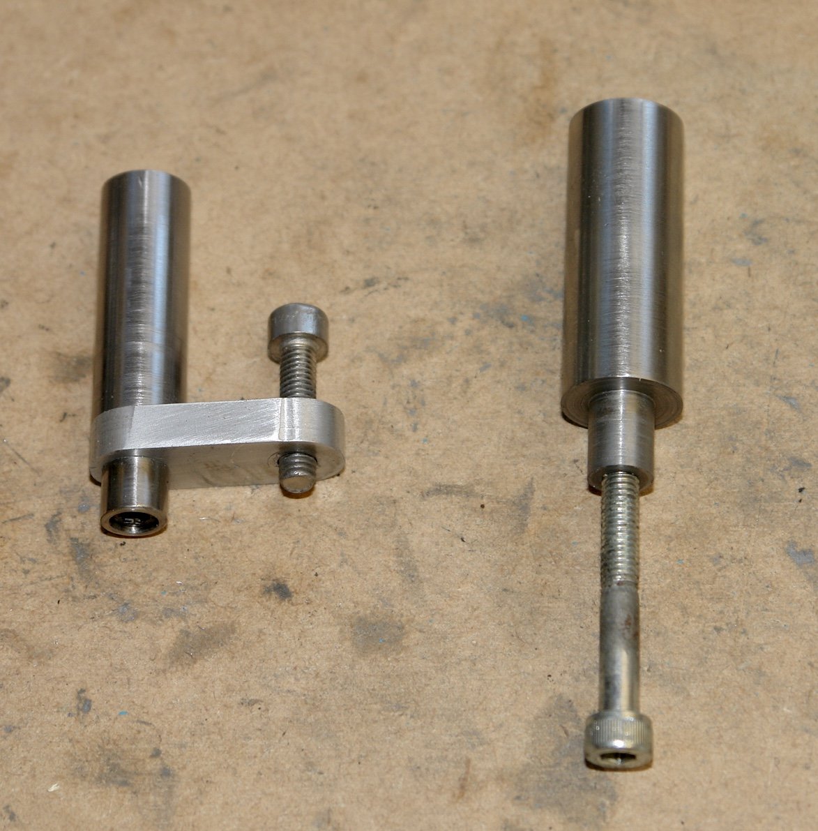
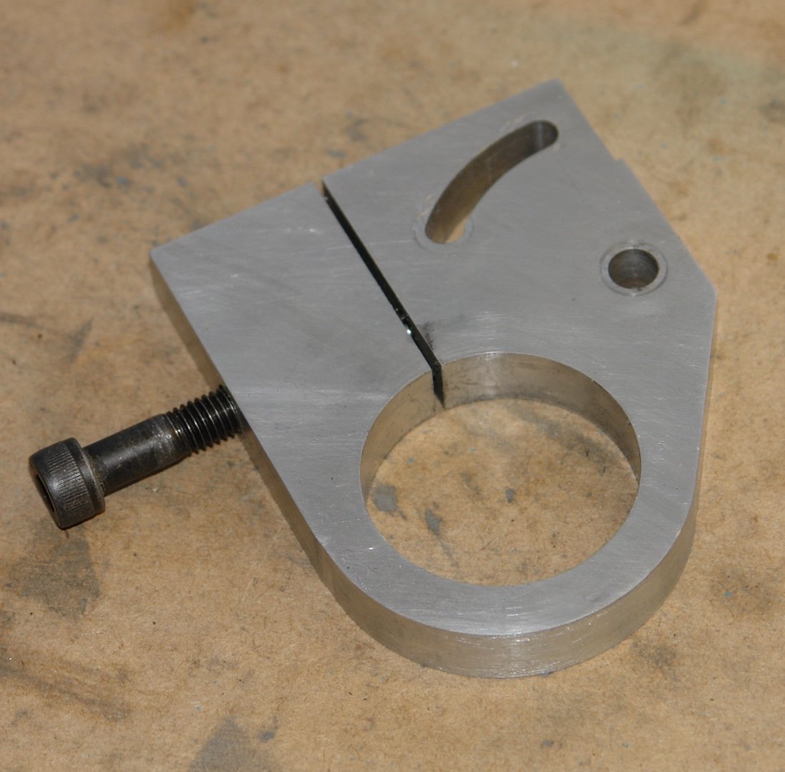
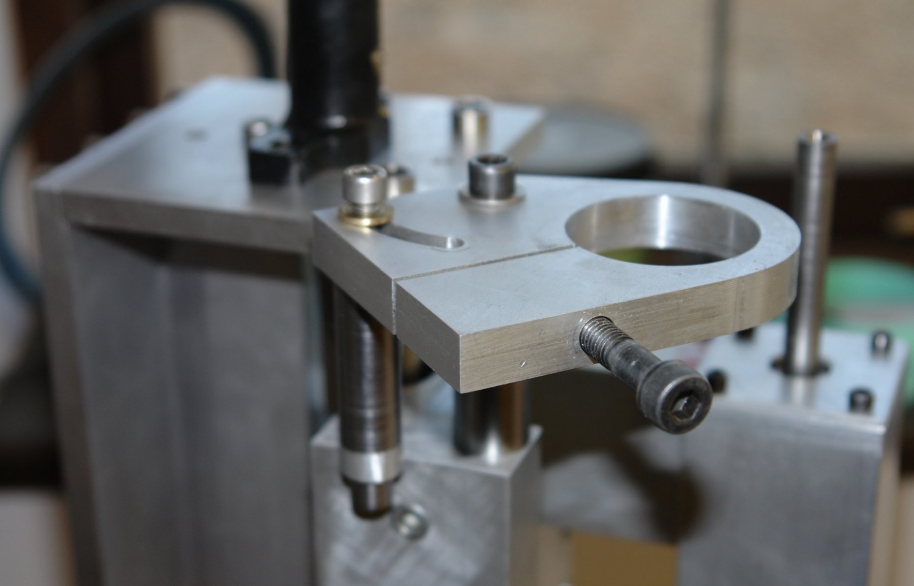
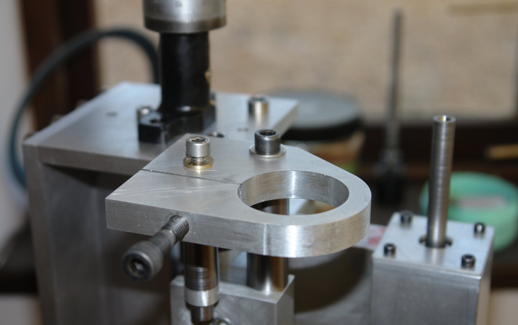
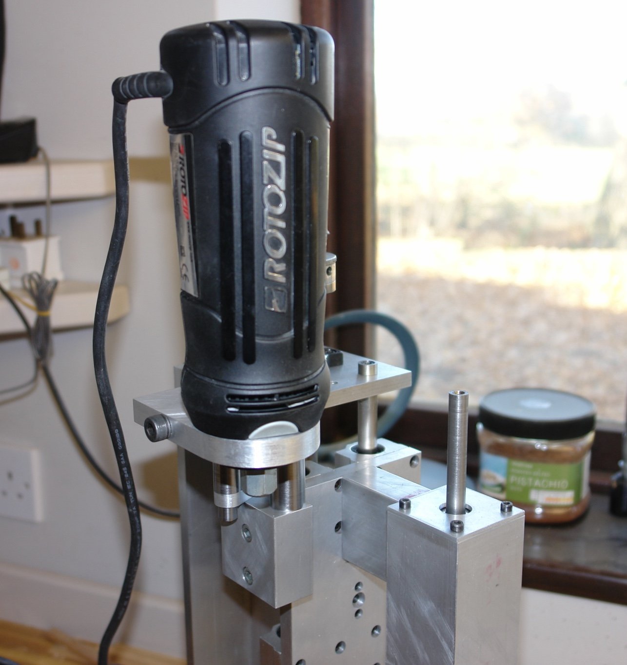
Thank you for the feedback Aviaamator. The next job was to sort out the motor mounting. I had drilled and tapped holes in the side of the sliding plate. On to these I mounted a 2"x2"x1" aluminium block, drilled to take mounting bolts and the up stands on to which the motor mounting plate was to be attached. 2" up-stands are required to allow room for the belt drive arrangement. One is fixed while the other swings on a short arm. The next photo shows the up stands fitted. The motor mounting plate clamps onto the neck of the rotozip body. The mounting hole was accurately bored and then split on one side using a slitting saw. A hole drilled at right angles to the slit takes the clamping bolt which pulls the mounting plate tight against the rotozip body. The up-stand on the swinging arm locates in the circumferential slot on the motor mounting plate. This allows the motor plate to be rotated to accommodate different drive belt ratios (different drive belt centre distances). The motor was then mounted.