KeithAug
-
Posts
3,986 -
Joined
-
Last visited
Content Type
Profiles
Forums
Gallery
Events
Everything posted by KeithAug
-
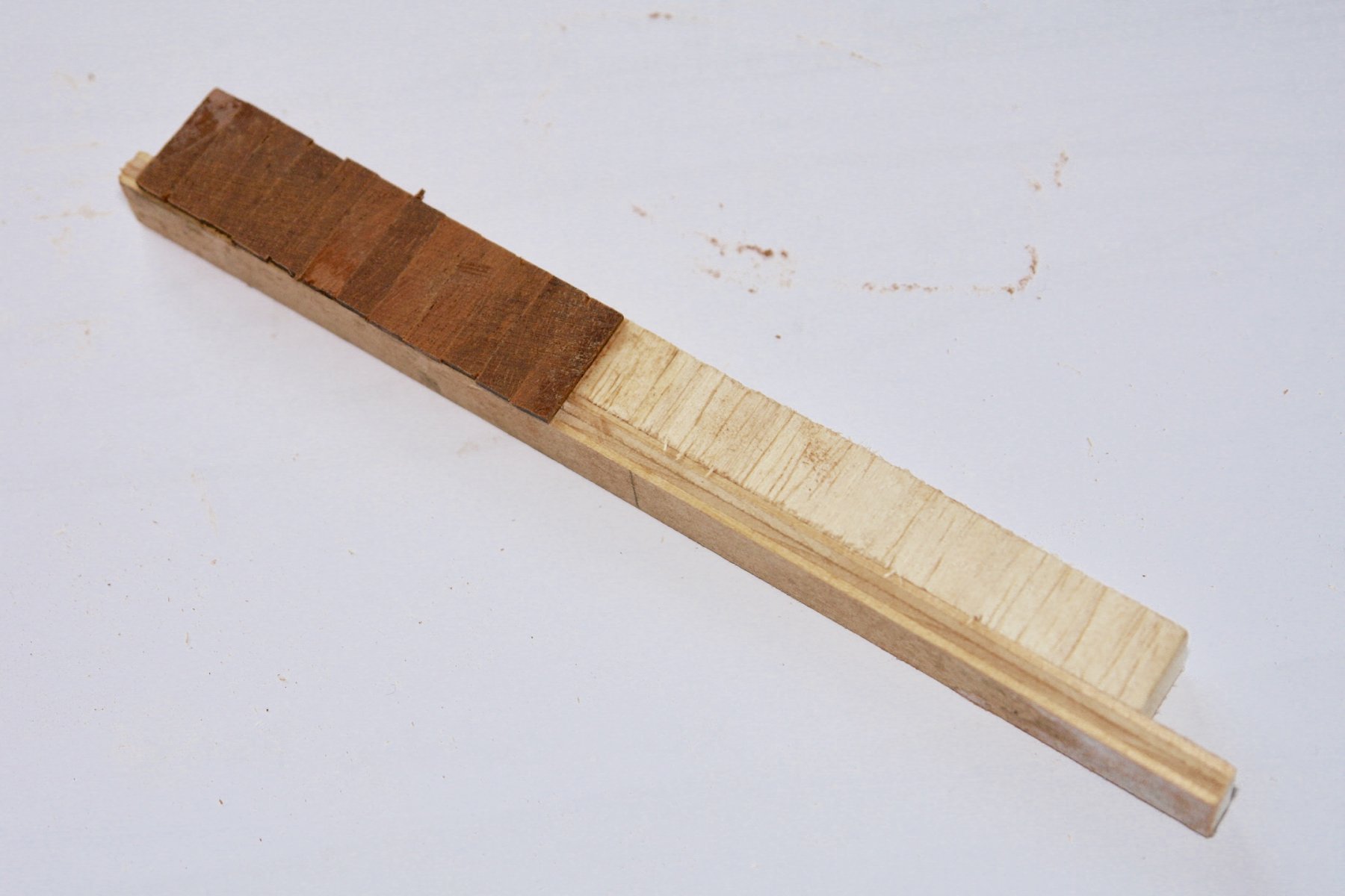
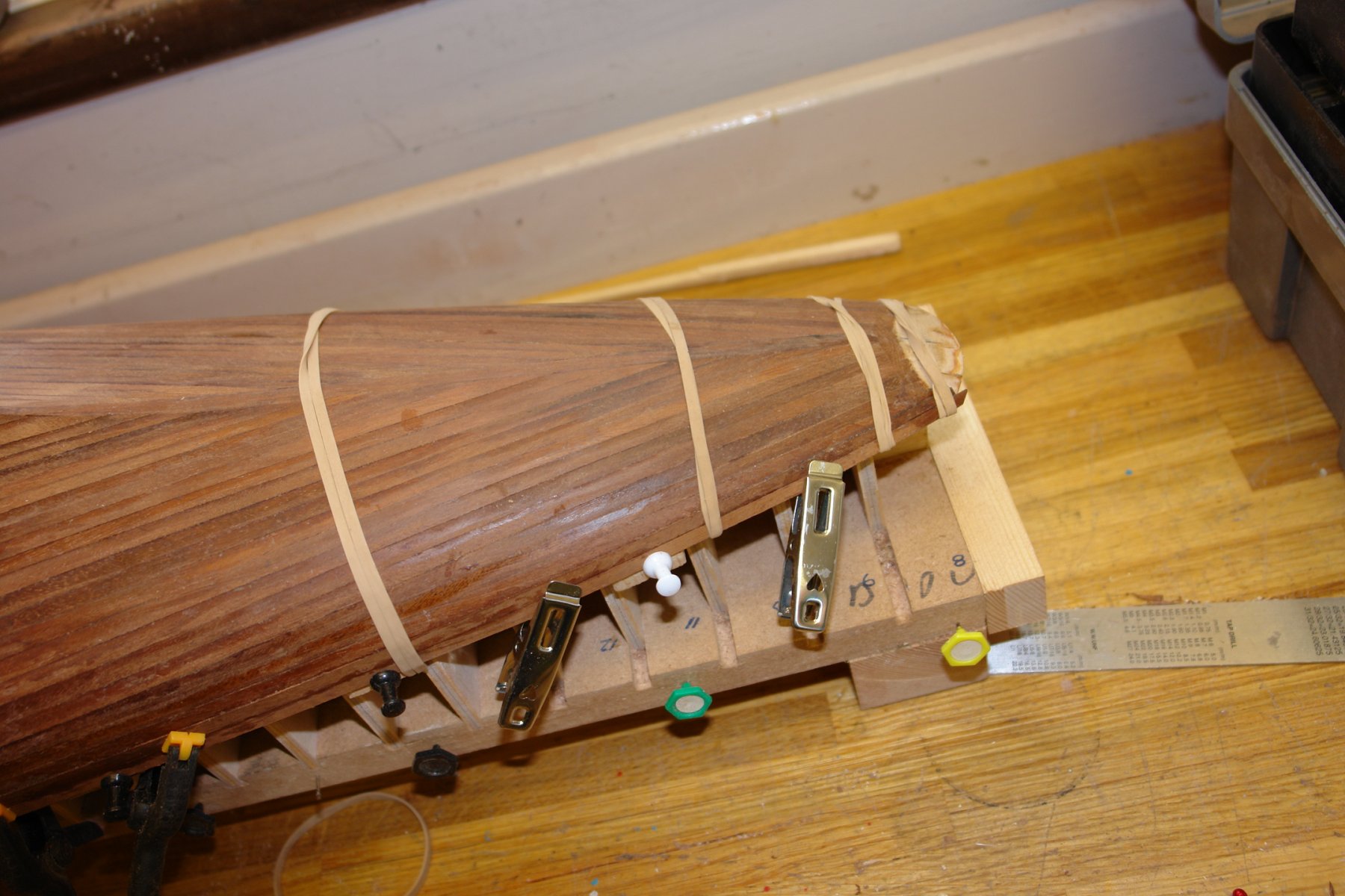
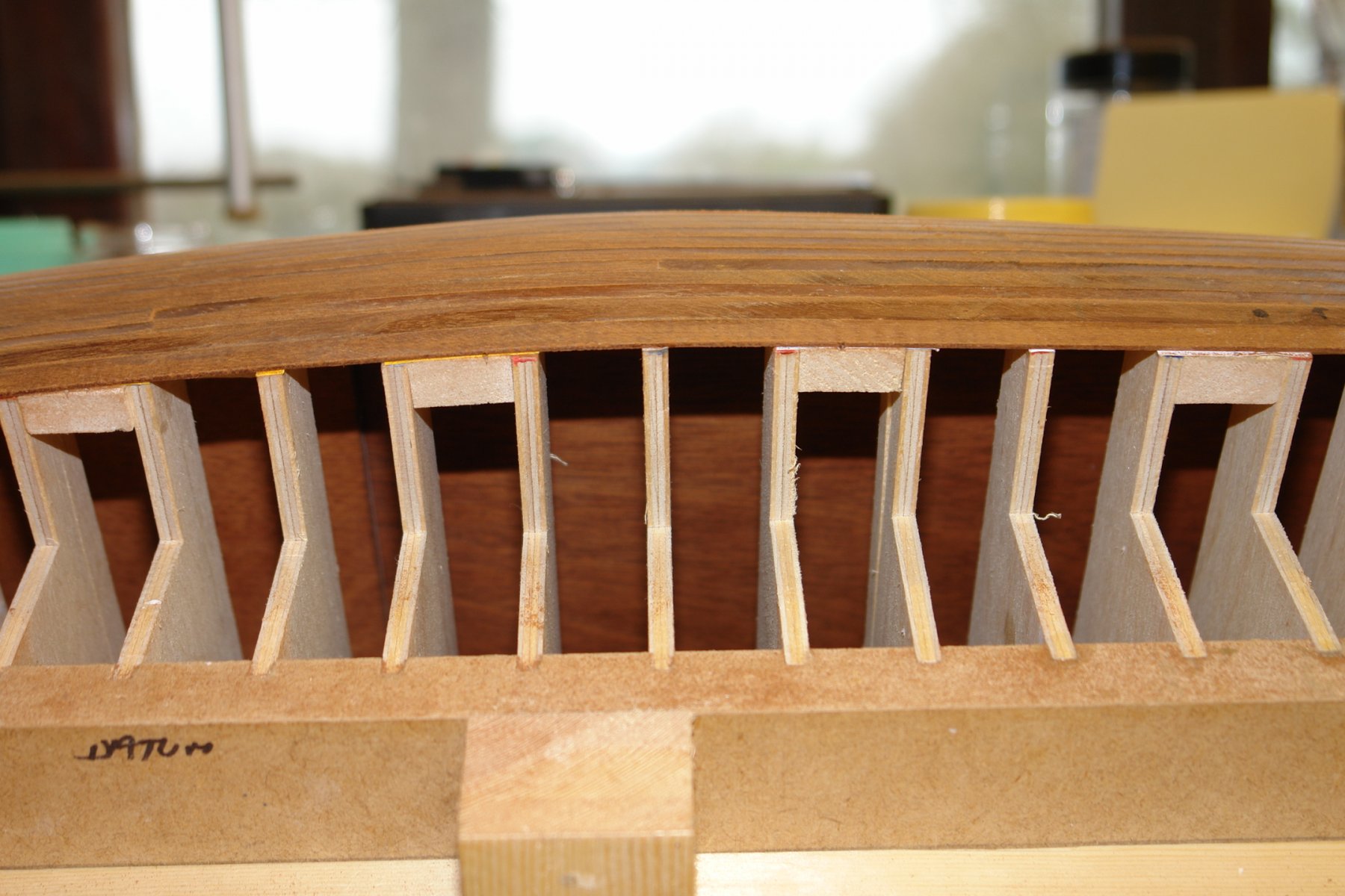
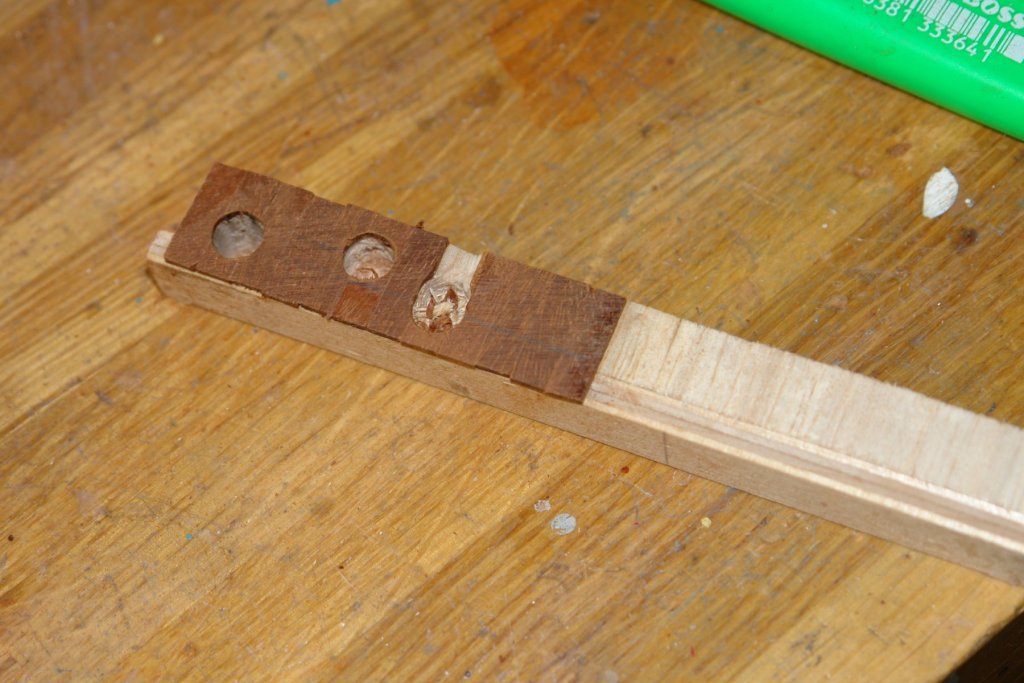
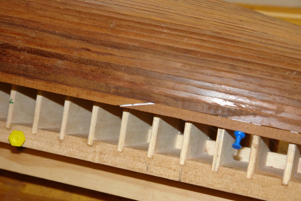
 Thank you Michael, John and Eberhard. Michael I think you and Eberhard are thinking along similar lines. I have ordered some silver steel rod and will make something along the line of these suggestions for drilling the holes in the bulwarks. I'll let you know how it turns out later. John - I was thinking about a bit of experimentation and here are the results:- I mocked up a section of hull simulating the frame and balsa capped by .050" thick mahogany planks from right to left:- Hole 1 spans the frame / balsa interface and was drilled with a 1/16" twist drill followed by a 3/32" and then 1/8" before being opened out with 4, 5, 6, and 7mm straight flute hand reamers mounted in my DIY hand drill (run on low speed). The final hole size is 8mm but I will open out the 7mm hole to 8 mm using 120 grit sandpaper on a conical former. This should give me smooth round edges. Hole 2 is completely in the balsa area and was drilled with a 7mm wood (twist) drill. It produced and acceptable result. Hole 3 spans the frame / balsa interface and was drilled with the 7mm wood drill. It did what I expected - the balsa not being strong enough to keep the drill point on centre, the drill stepped sideways on contact with the frame and ripped out a section of plank. I drilled one hole in the hull using method 1 and then opened out to 8mm using the cone sander. The result looked good, hopefully it wasn't just a lucky first strike.
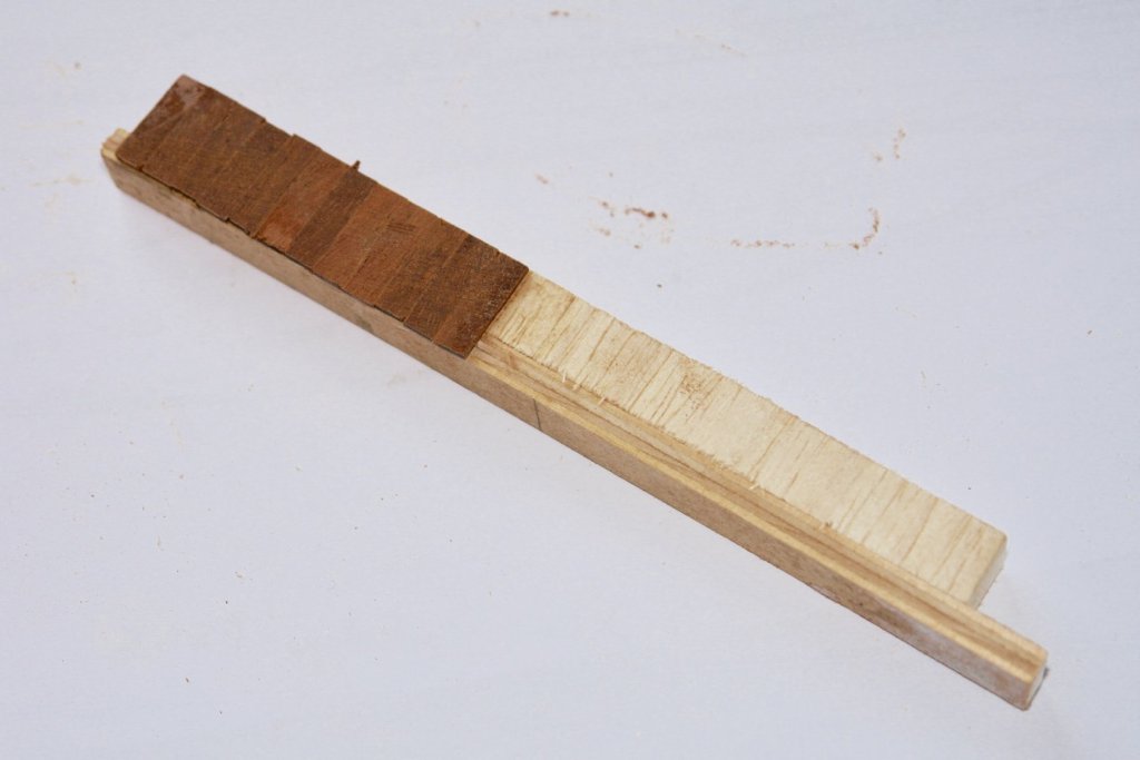
-
Excellent Paul - I assume the garage has emerged from the winter freeze.
-
Kortes - you are very quick yet still maintain wonderful quality.
- 306 replies
-
- 4
-

-
- schooner
- la jacinthe
- (and 1 more)
-
Eberhard - Also seems like a good idea, although a little more complicated. I think I will try the reamer first on the test piece and then follow your suggestion if it does not work. The planks are of course glued on to the frames / balsa infill which should help resisting splitting or plank separation at the joints. I do of course have to drill holes through the bulwark at some point in there future where I am sure I will need your method. I did do a bit of a web search and as you say I couldn't find Forstner bits small enough. I am leaving the question re the extent of painting open for a while.
-
Druxey - I don't have a suitable Forstner bit so I will try the progressive opening up of the hole first. The finished hole size is 8mm (.315").
-
Dave - thank you for the advice - i was thinking along those lines but having first hand input is a good confidence boost. I was planning to do a test run on a mock up of a hull simulation so I will definitely be experimenting with your approach.
-
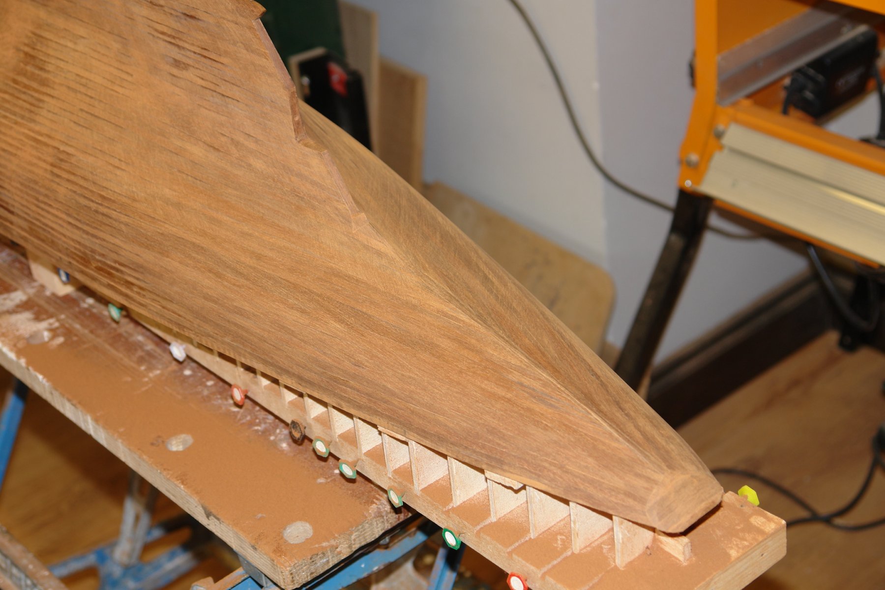
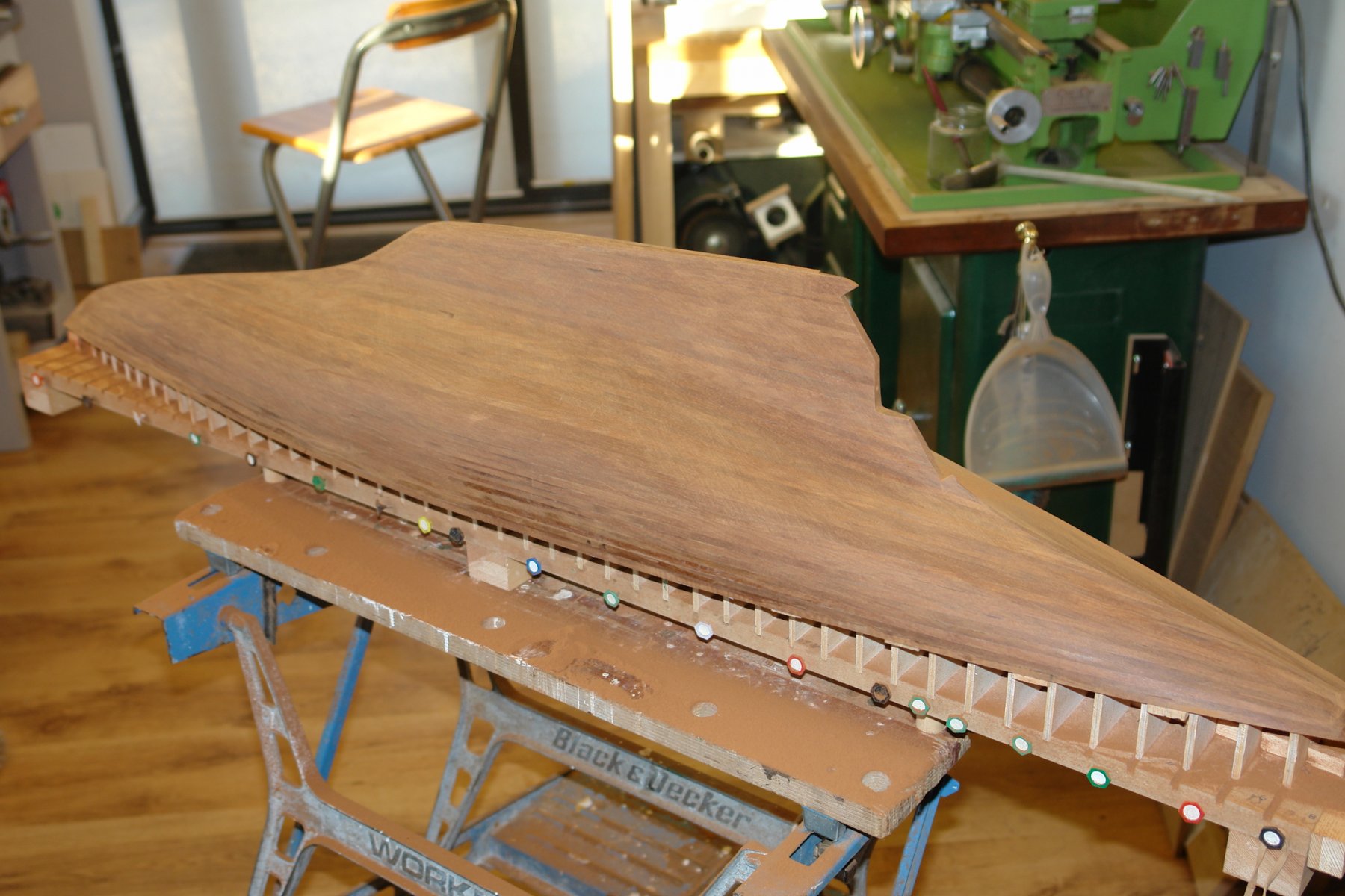
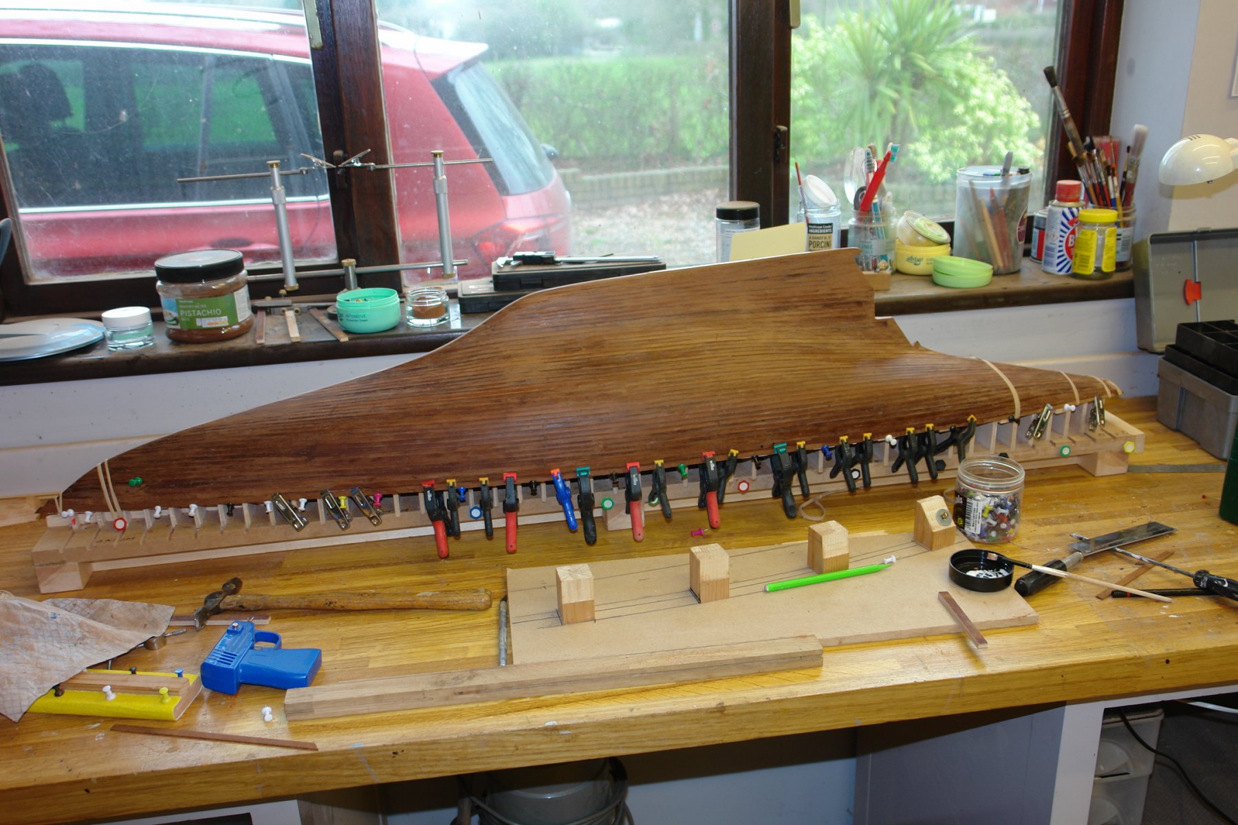
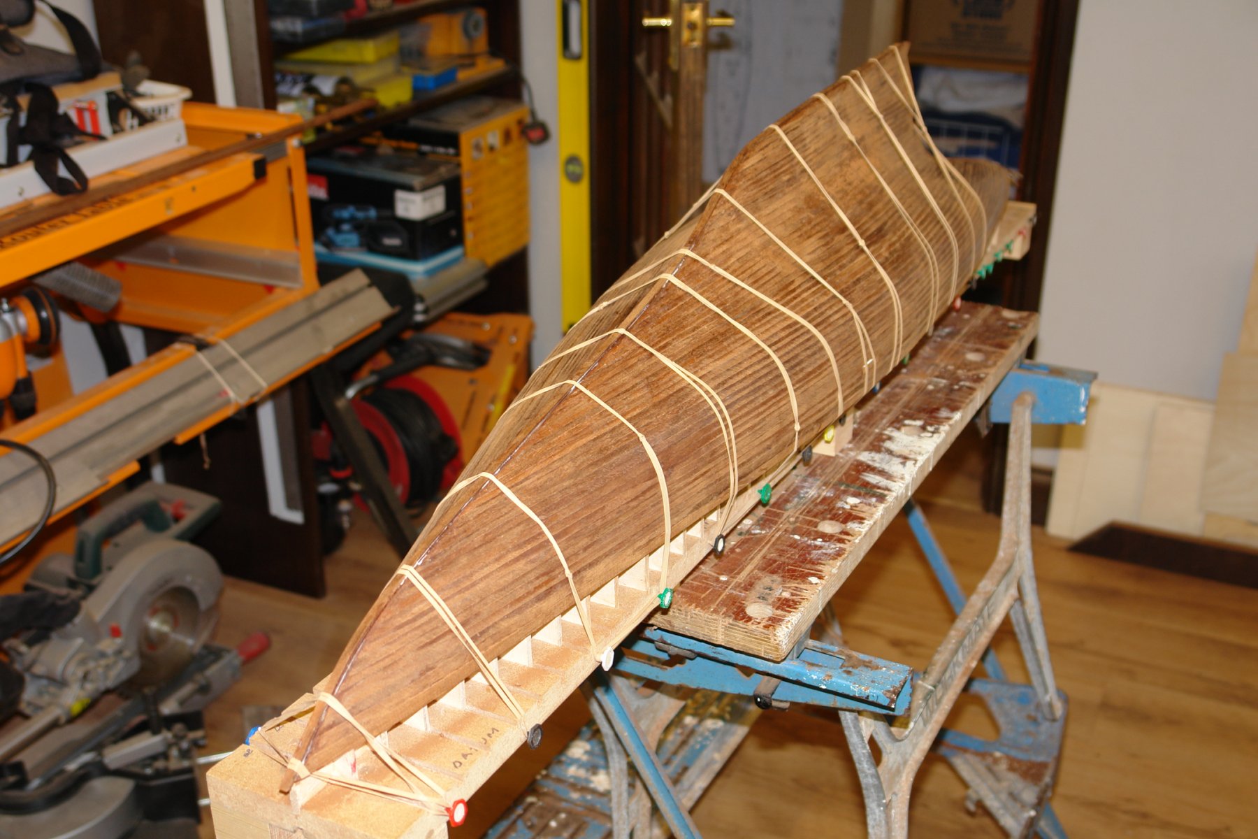
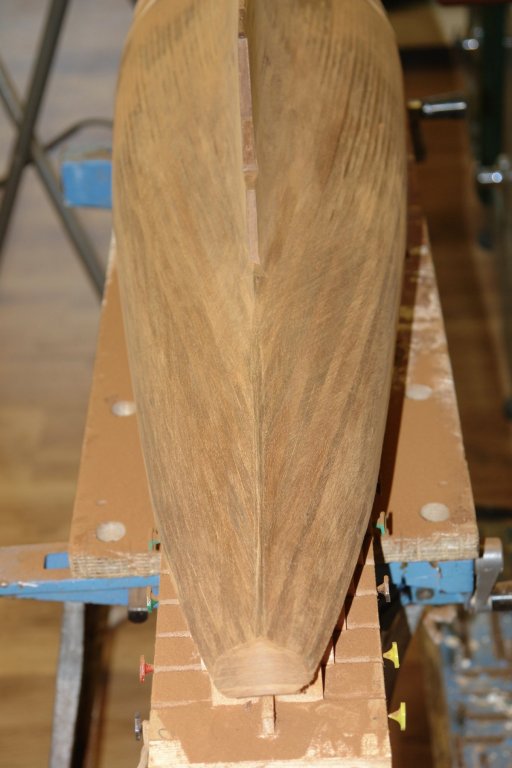
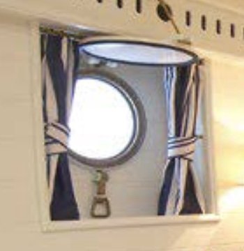
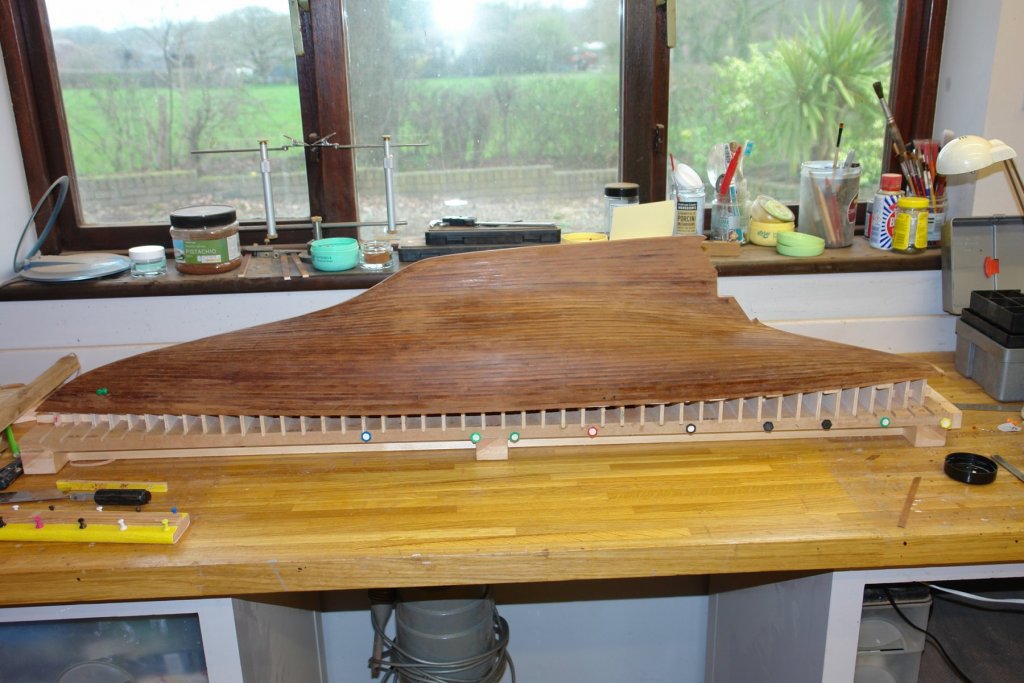
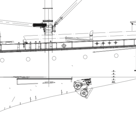
Pat / Kortes - thank you for your continued support. Planker's Progress 11 - Day 24. This morning was a sanding marathon - about 4 hours with a 15 minute break. This was coarse sanding to blend the planks and I used a good quality 60 grit paper on my long cork sanding block. I started at the stern where I sanded away most of the keel plank but I did achieve the clearly defined edge that I was looking for. I also carefully sanded the transom to create the required definition. You can clearly see the difference between the fully sanded and partially sanded areas in the next photo. At this stage I stared to think abut the rows of 15 portholes down each side of the hull. They appear as modest / simple affairs but are recessed below the hulls surface. This poses the problem that holes have to be cut with crisp edges as any imperfections will not be masked by a porthole flange. A lucky spot was the realisation that the port and starboard port holes are pitched differently. I think I will worry the drilling operation to death over the coming days. It wouldn't be good to spoil the hull at this point. I do question some of the design aspect of Germania. It is clear from the picture that the port hoes will be below the waterline when healed. I can't believe that some well pickled guest( high on gin from the night before) isn't going to forget to secure the cabin before venturing onto deck for their morning tipple. I think if I were the owner I would rely on the deck vents and have the port holes bolted shut. I decided not to complete the sanding along the line of the port holes feeling it would be better to do this once drilling is complete. Leaving this area only partially sanded also means that I can more easily judge the position of the holes relative to the plank edges. Sanding dust now covers almost every surface in the workshop.


-
Carl - I think this is the size you need. diameters are correct but I have not checked thickness . But you should be able to sort this out with a file. https://www.ebay.co.uk/itm/Saw-Blade-Bore-BUSHES-Saw-Reducing-RINGS-Bushing-WASHERS-Sawblade-SPACERS-/160910979685

-
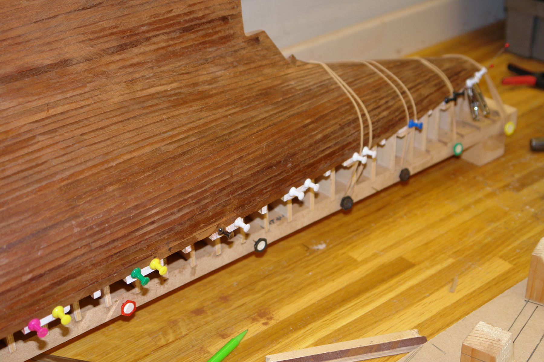
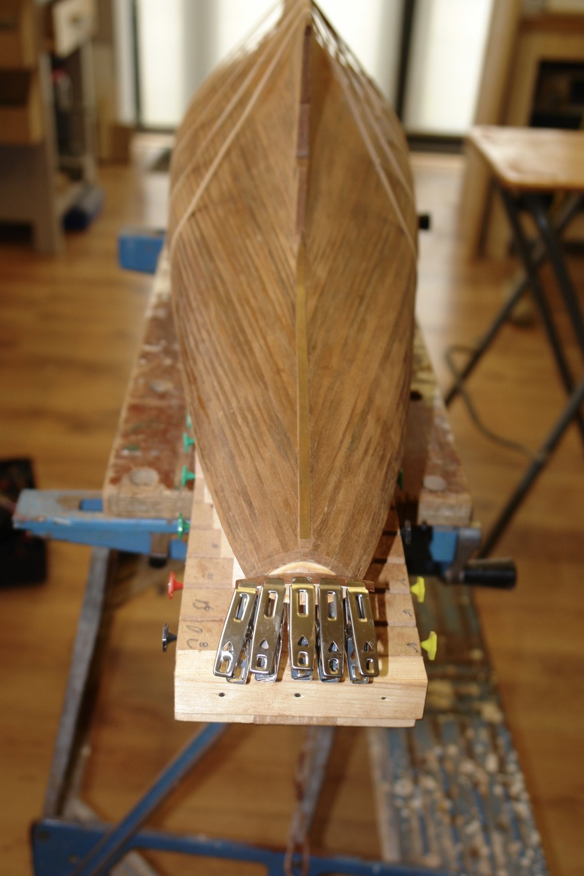
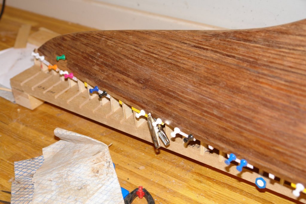
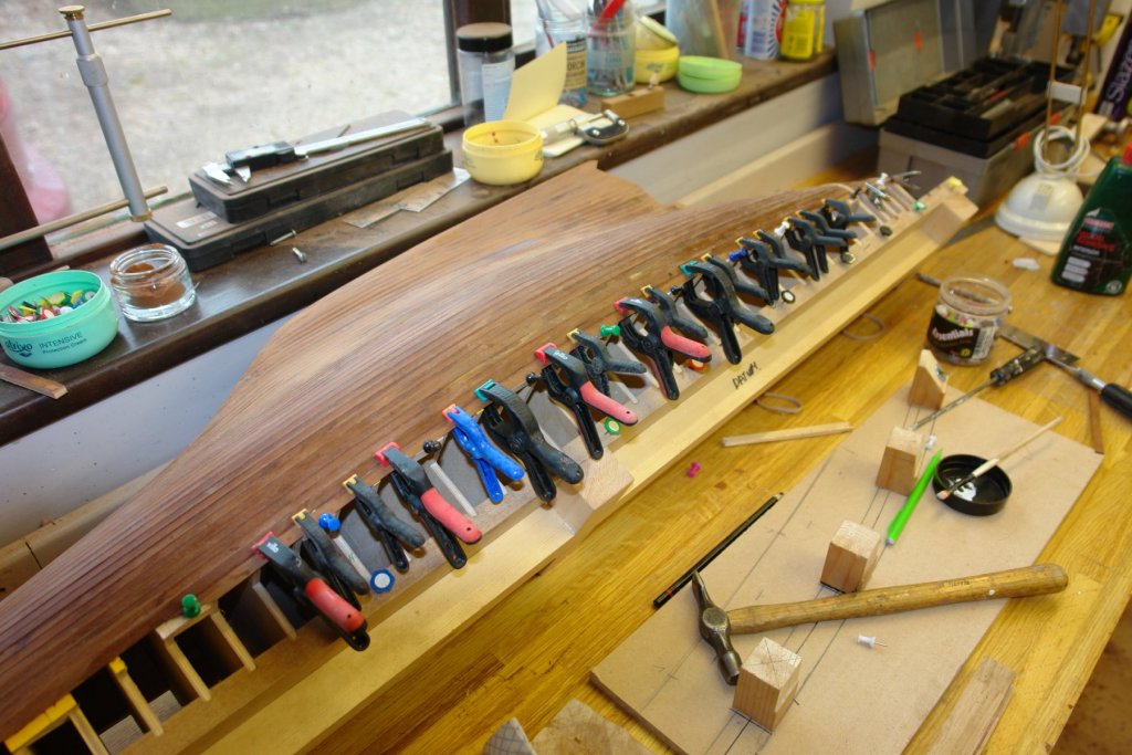
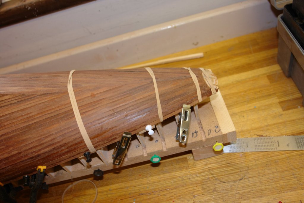
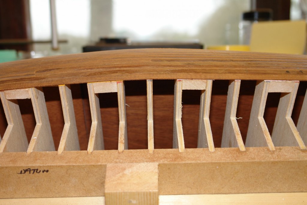
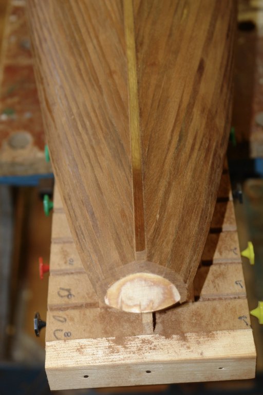
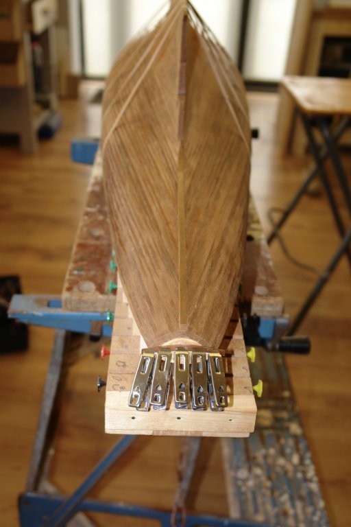
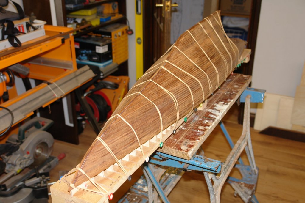
And so back to the routine:- Planker's Progress 10 - Days 22 & 23. I left you with the first bulwark plank curing in the jig designed to twist and bend it. Well it sort of worked!!!!!!!. I should have overdone the curve and twist because when I released it it sprang back by about 50%. I ended up putting more bend and twist in by hand aided with a hot air gun. This worked so well that I dispensed with the jig for thew remaining planks. I made sure that shear plank edge was well coated with PVA to give it the best chance of surviving removal of the frames. I held it in place while drying with plenty of pins and a few clothes pegs. The 2nd of the 2 bulwark planks was equally well glued and I used a few clamps to make sure that the edge to edge alignment was correct. Ok - probably more than a few clamps. The worrisome stern planks went on better than I expected. Must remember not to worry so much in future. With the clamps removed the final form of the hull magically appeared. In the next shot you can see how delicate the bulwarks looks. Then it was on with the other side. I should have explained earlier that the wood I had wasn't long enough to lay single lengths of bulwark plank. In order to get the bulwarks as strong as possible I scarfed the joints. In all the activity I bashed the transom and had to re-glue and sand it. So I decided to over plank it with .025" thick planks. I think the following photograph is what is referred to as a fantail. All those fans of a varnished mahogany hull should not get their hopes up yet! Almost ready now for some serious sanding, but first I needed to add an additional plank along the keel - necessary to ensure that I could sand to a sharp edge as per the original.


-
HMCSS Victoria 1855 by BANYAN - 1:72
KeithAug replied to BANYAN's topic in - Build logs for subjects built 1851 - 1900
Loved the little saw jig and holding feature Pat. Something to try in the future.- 1,013 replies
-
- 6
-
-
- gun dispatch vessel
- victoria
- (and 2 more)
-
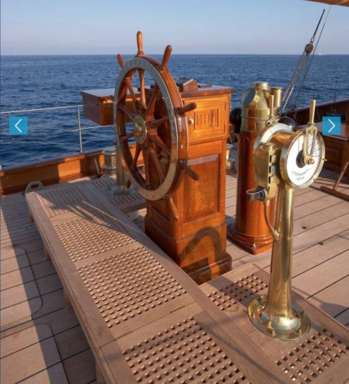
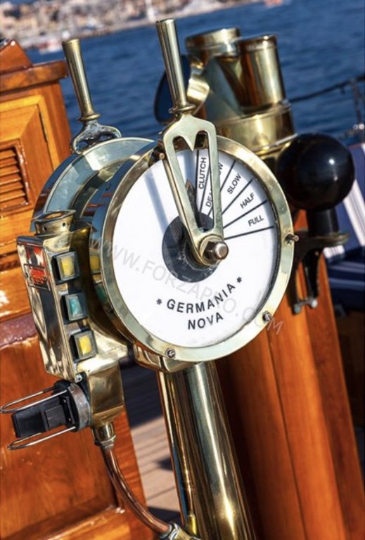
Roger - thank you fo your positive comments. As Bedford has pointed out - one handle is for the speed control and the other side is forward and reverse. A bit odd as both functions are on the same handle on all the yachts i have sailed on. A more logical arrangement for me would be to have throttle forward and reverse on one handle and the bow thruster on an other. Yes - she does have a bow thruster - retractable into the hull. Eberhard - thank you - I may try something similar. Keith - he is just a bit perfectionistic. It is probably an age thing. Pat - not sure filing it down would satisfy Mr M. Valeriy - thank you. Vossie - fortunately its an experience of life I have managed to avoid.
-
Eberhard, Pat, Bedford, Keith, Druxey John, thank you for your comments - much appreciated. Michael - even critical prompts are very welcome.
-
WoodButcher Im fairly sure that Cornwall Model Boats ships worldwide. I have used them in the past and always been pleased with the service. https://www.cornwallmodelboats.co.uk/cgi-bin/ss000001.pl?page=search&SS=steering+wheel+for+speedboat&PR=-1&TB=O&ACTION=Go!. lovely model .
-
Nicely done Michael.
-
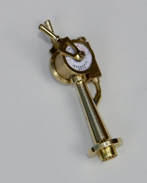
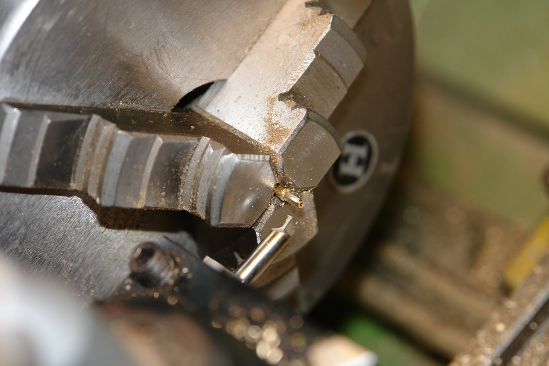
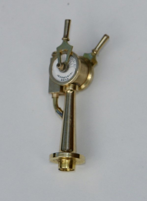
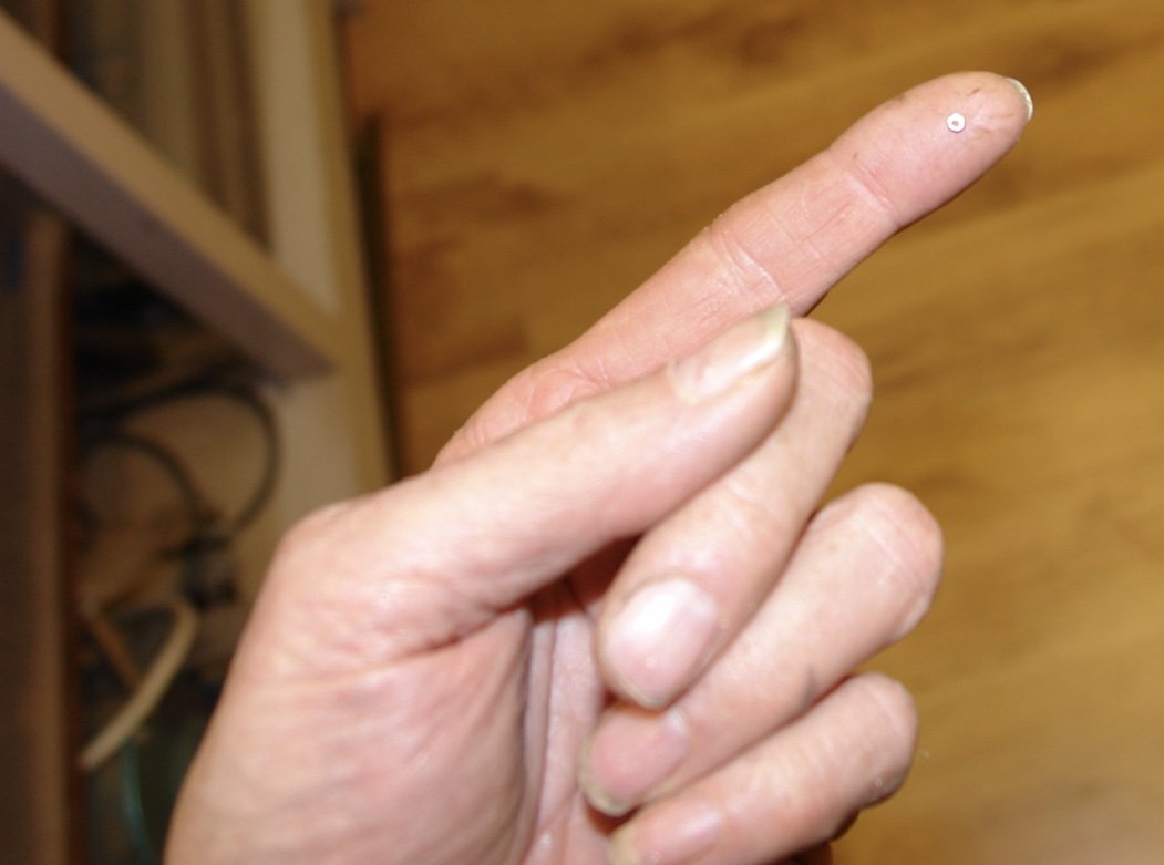
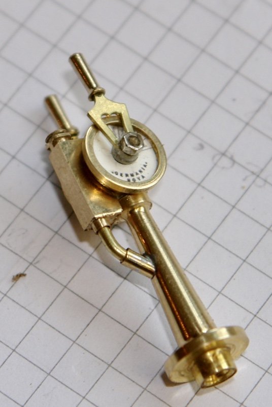
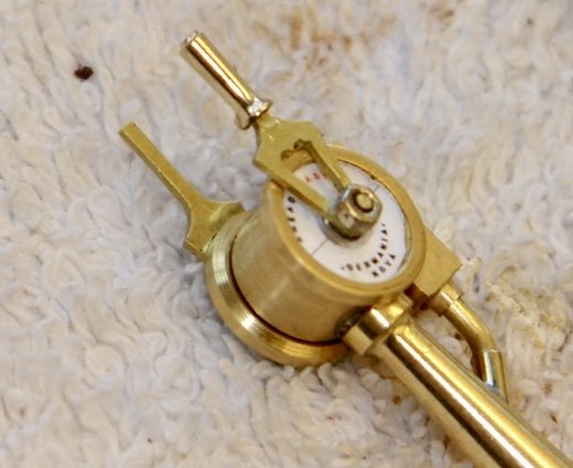
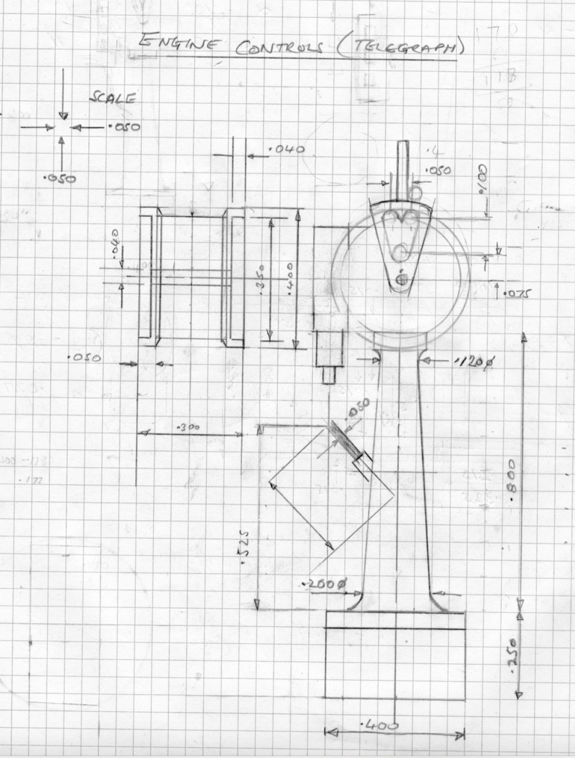
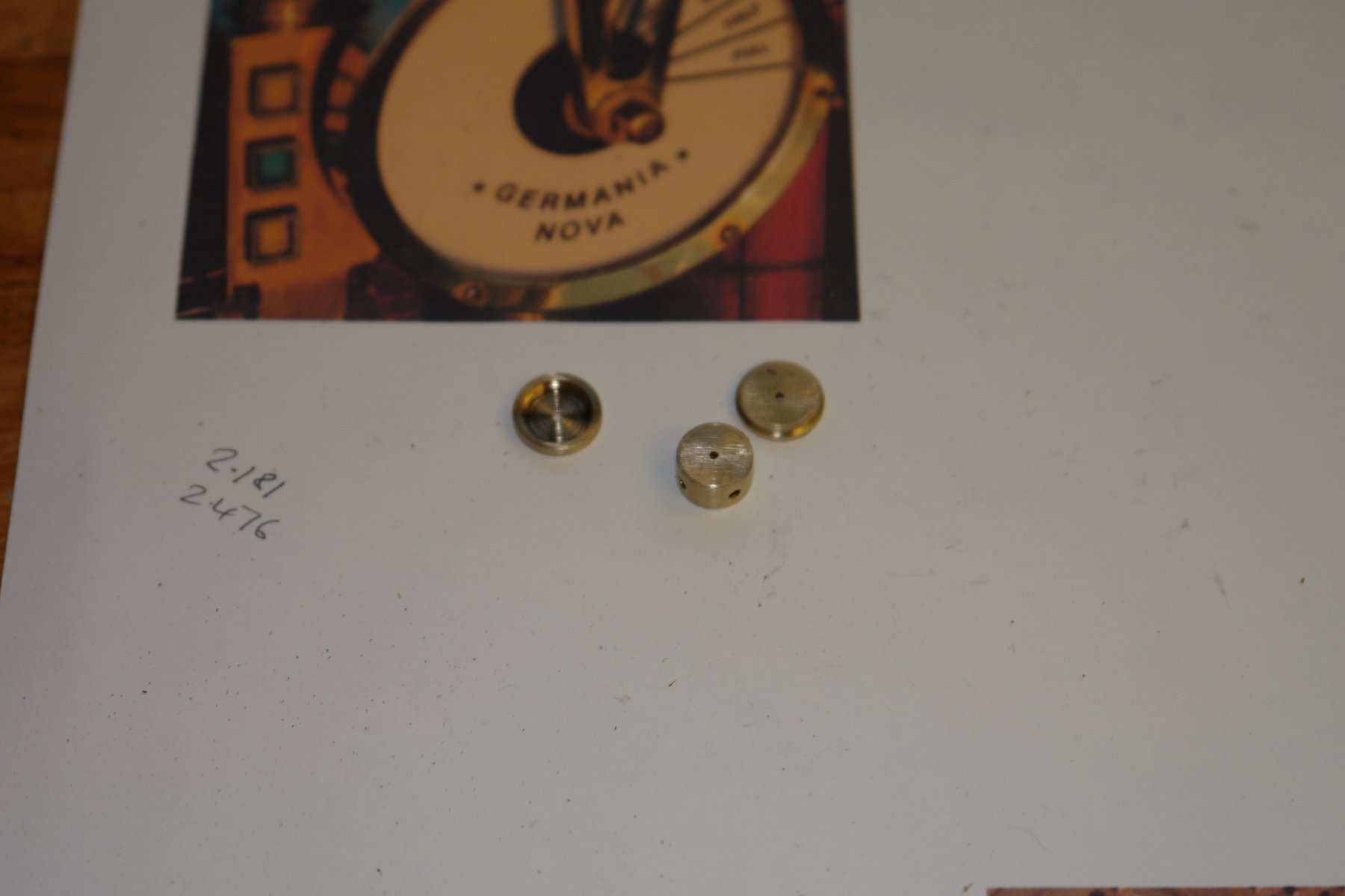
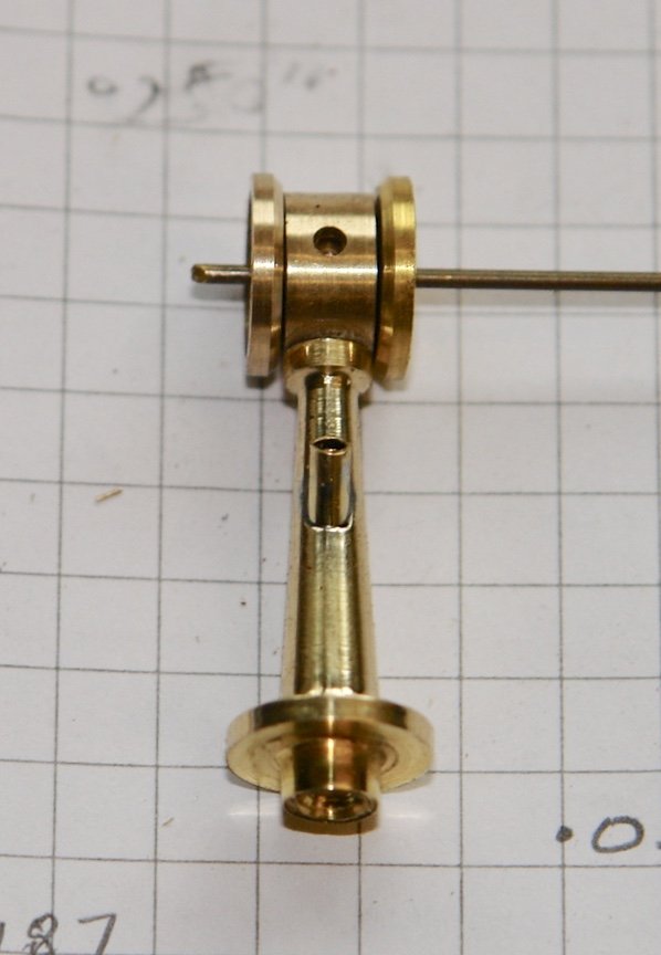
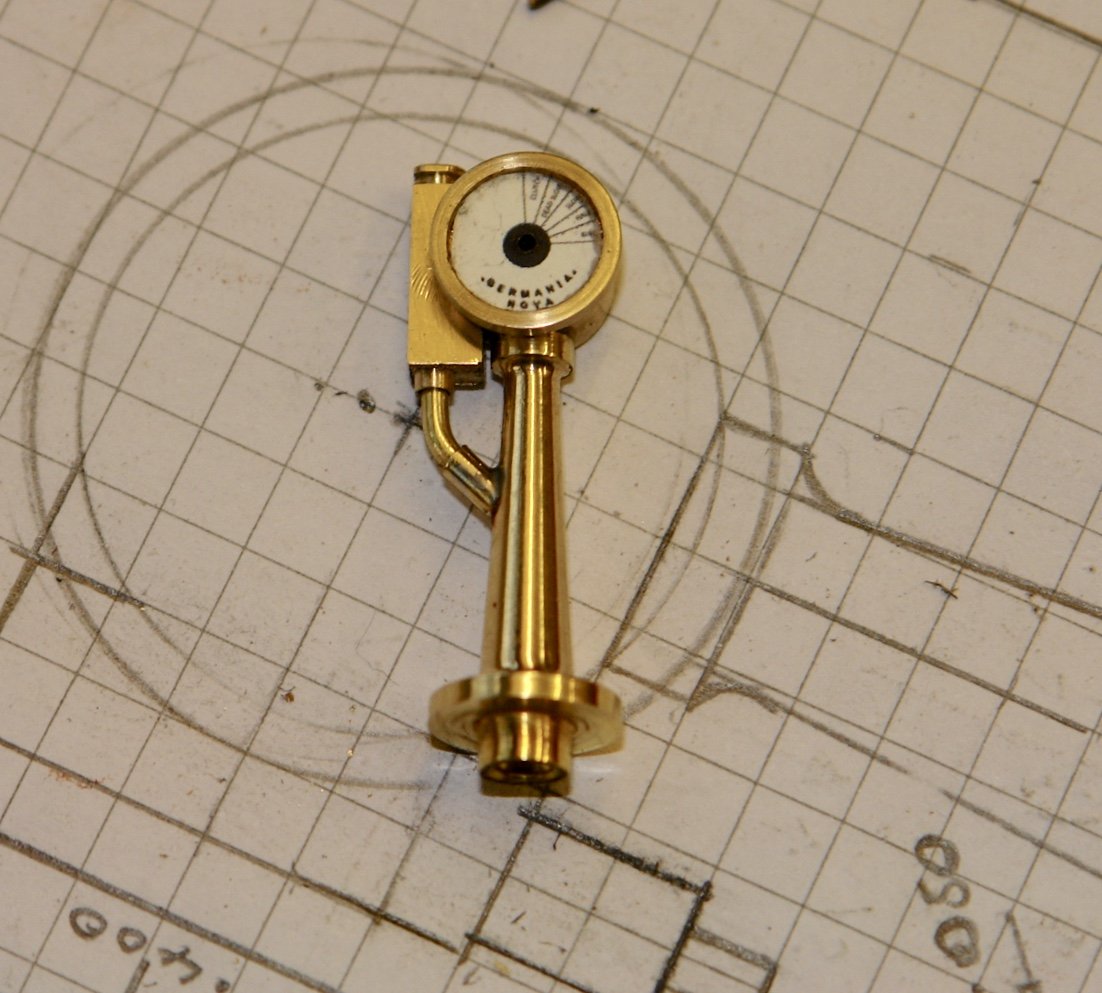
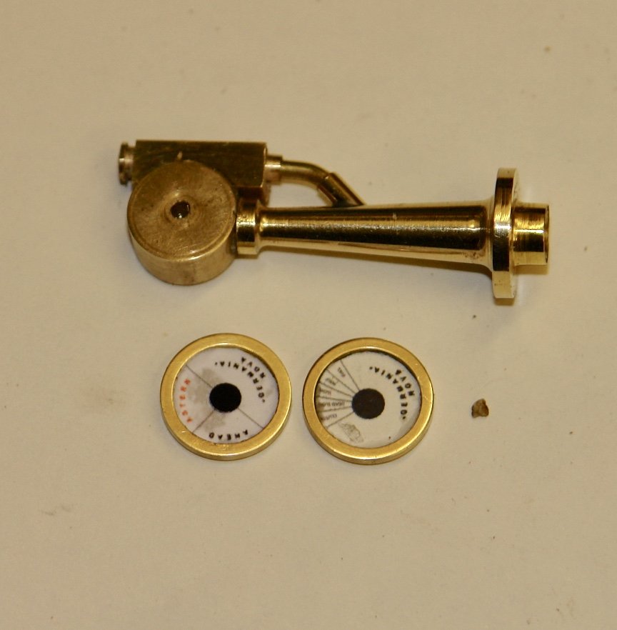
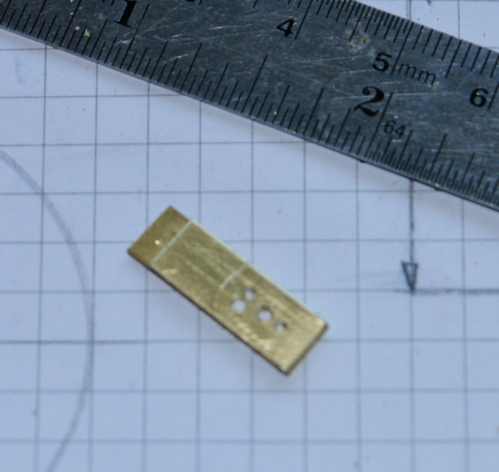
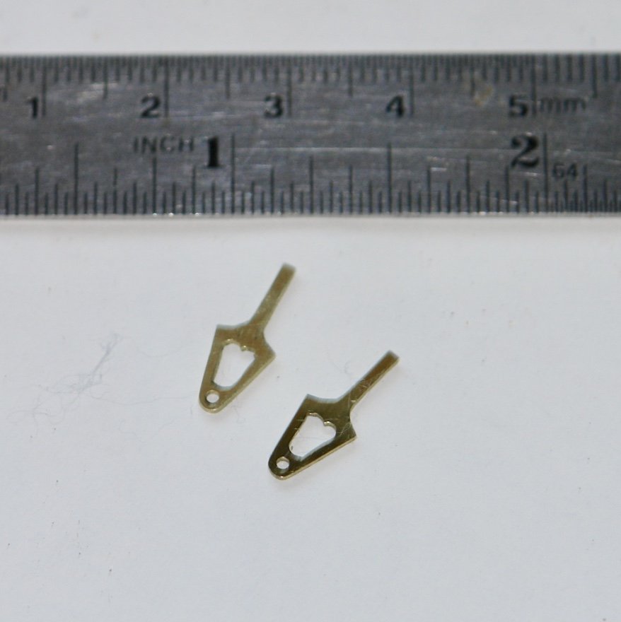
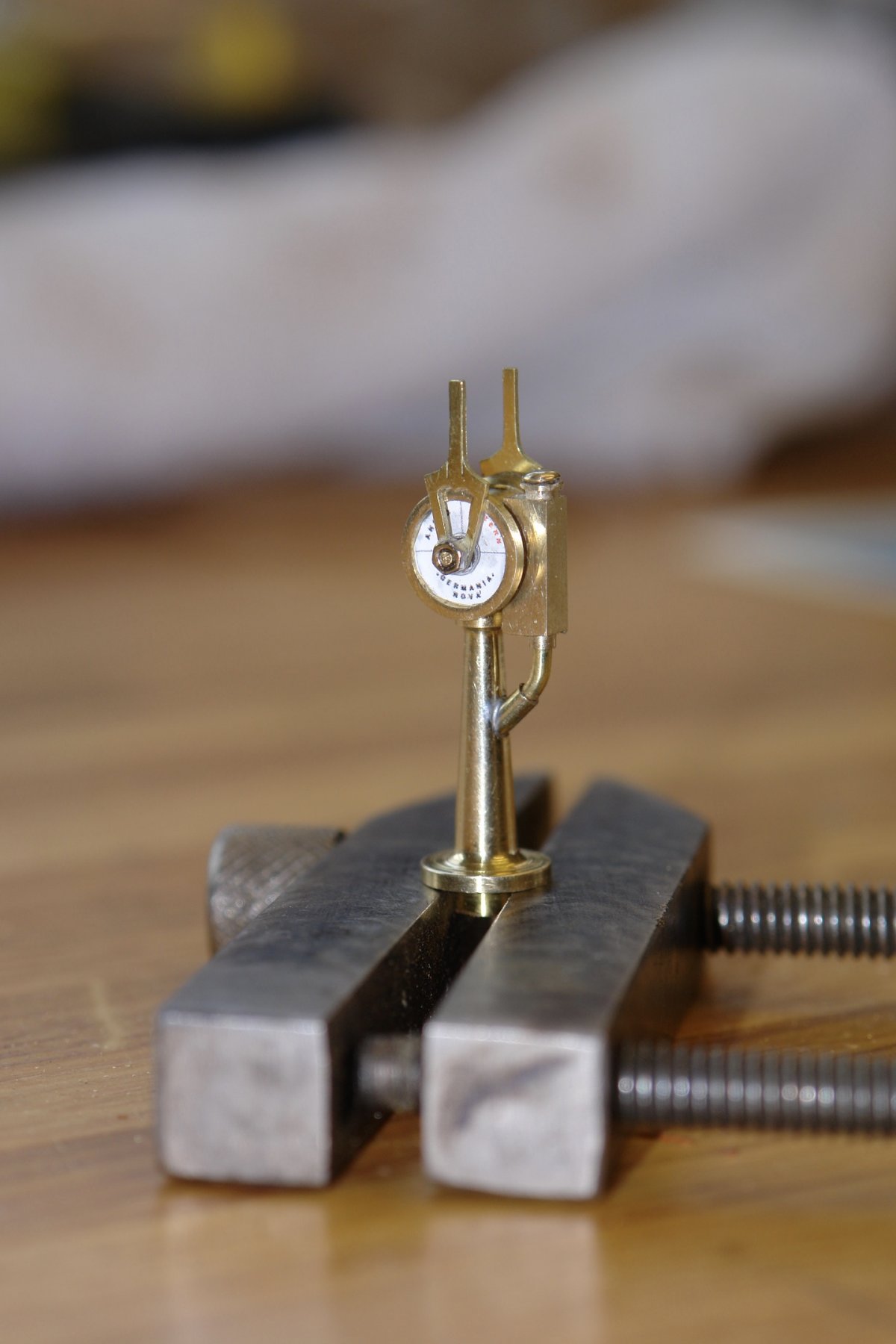
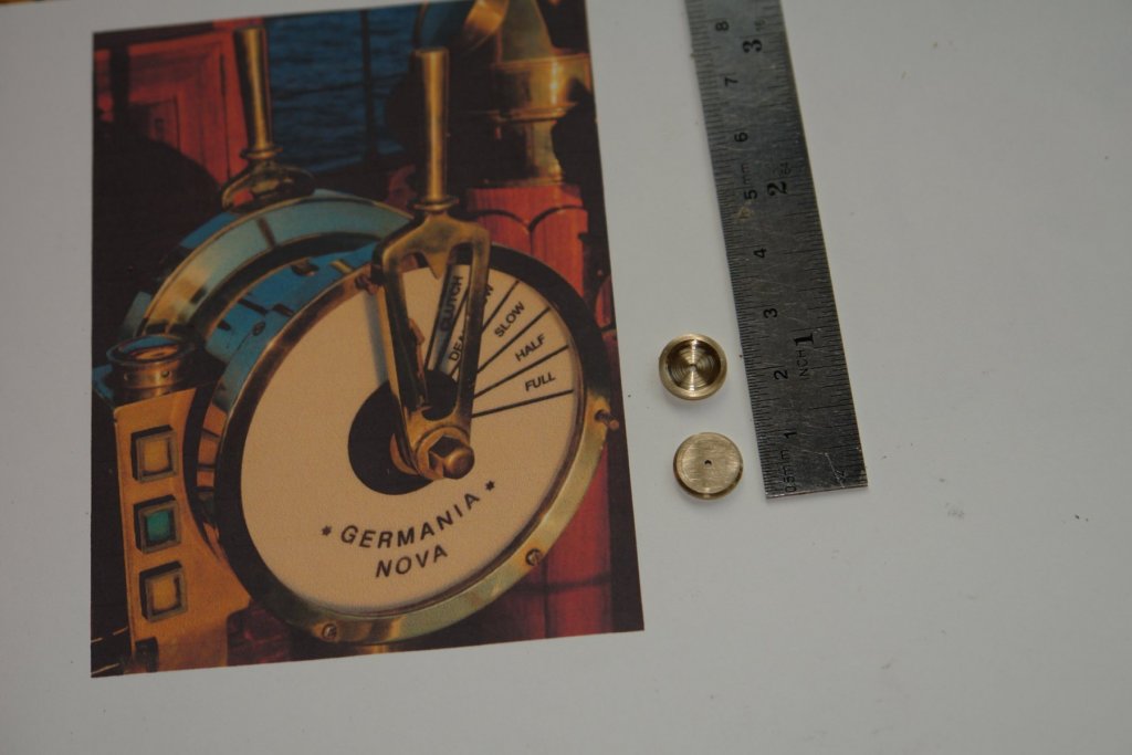
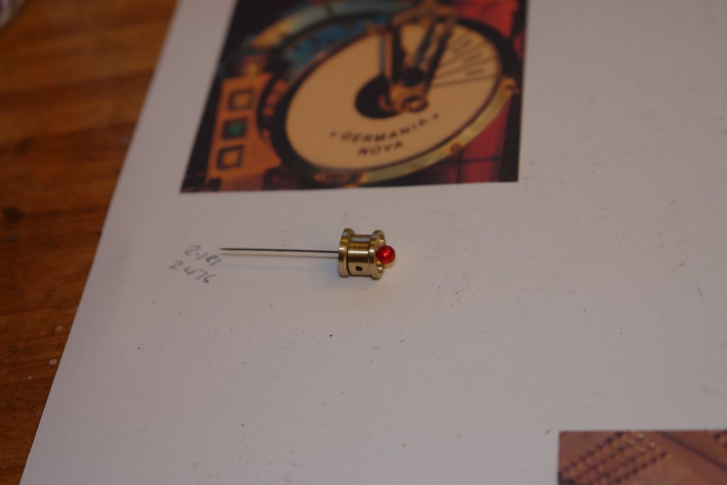
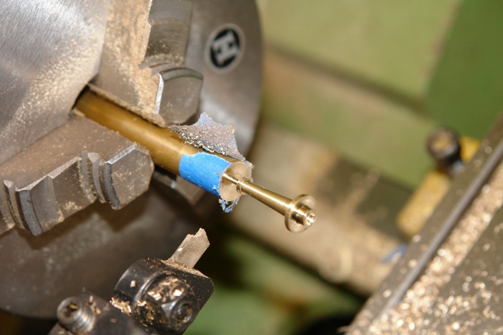
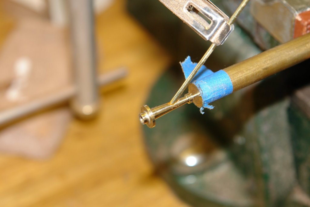
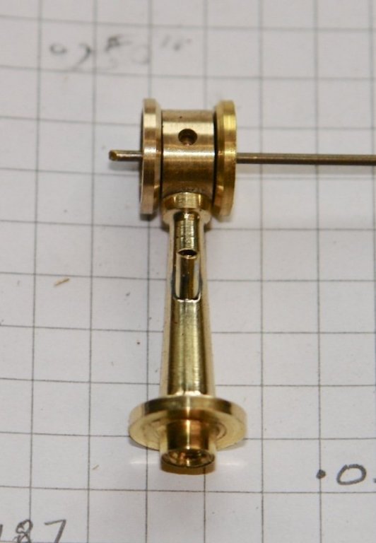
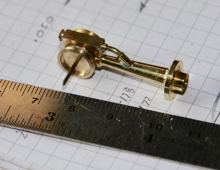
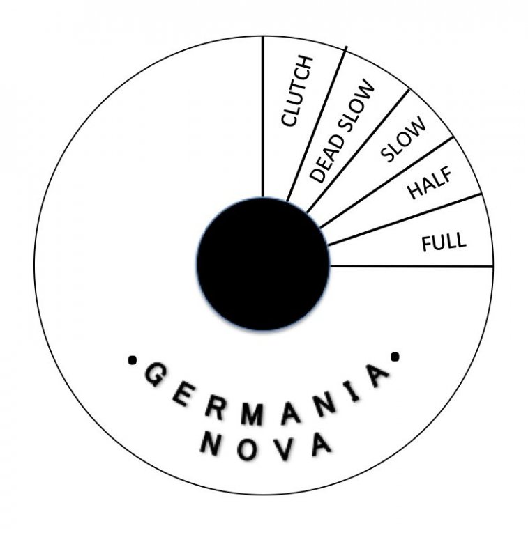
Gary, Michael, Pat - thank you for your comments - and thank you to all other visitors. I got to a point where I needed some therapy so I abandoned the planks for a couple of days (I am probably still worrying about the bulwarks). I have been thinking about the engine control column - fashioned in the style of a ships telegraph. I had plenty of reference photographs from which to draw a plan. The height to the centre line of the throttle controls is 1 inch. I made the dial in 3 pieces because It avoided having to turn the part round in the lathe to machine the reverse face. The recesses in the faces were cut with a 6mm 2 flute end mill mounted in the tailstock chuck, followed by a 8mm 4 flute end mill. The central boss had 2x .060" holes drilled at right angles to take the pedestal and to mount the control box. The 3 parts are placed on a pin to show the assembly. The pedestal was turned from 11mm rod (0.433") which was pre drilled at 45 degrees for later addition of the boss which takes the cable tube. The cable tube boss was soldered in place before being cut to length. The pedestal then went back on the lathe to be parted off. The control box was milled out of a piece of .250" diameter rod and then mounted (glued using CA). The cable duct was just a piece of bent .060 brass rod. I drew the faces for the dial in powerpoint before reducing them to 8mm diameter. I can't read the dials at this size but surprisingly they do become legible when photographed. The faces were glued in pace with CA - which soaked through. (only a problem in the photographs and cant really be seen on the original) I folded a piece of .025" thick by .250" wide brass strip to get 2 thicknesses from which to make the handles. I then drilled this to take the shaft and to form the cut out. I cut the handles out using a jewellers saw and then filed both while still joined. I then assembled the whole thing - not very much for 2 days work.


-
Carl - I made it from aluminium - I have a lathe. However Jim sells spacers through the Byrnes web site for $5. You need to tell him the size you want.
-
Kortes Impressive but I don't think my eyes are up to it. With a little modification I might be able to make it work on the lathe.