HOLIDAY DONATION DRIVE - SUPPORT MSW - DO YOUR PART TO KEEP THIS GREAT FORUM GOING! (Only 51 donations so far out of 49,000 members - C'mon guys!)
×


KeithAug
-
Posts
3,960 -
Joined
-
Last visited
Content Type
Profiles
Forums
Gallery
Events
Everything posted by KeithAug
-
 Vossiewulf - Yes it can still be bought in both old and newer versions. The whole book is a fascinating read.
 -
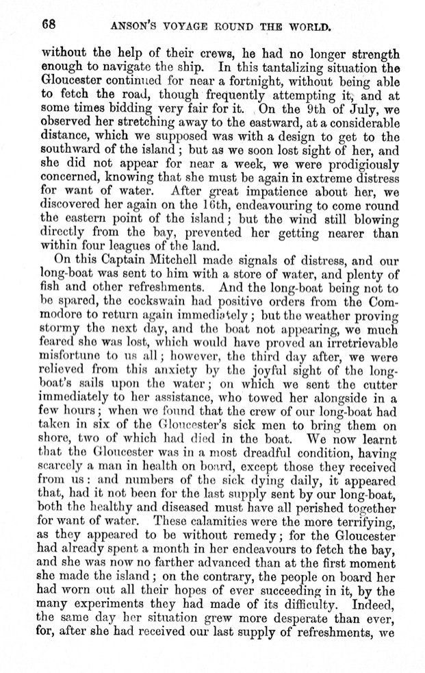
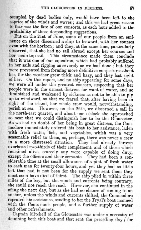
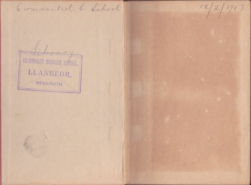
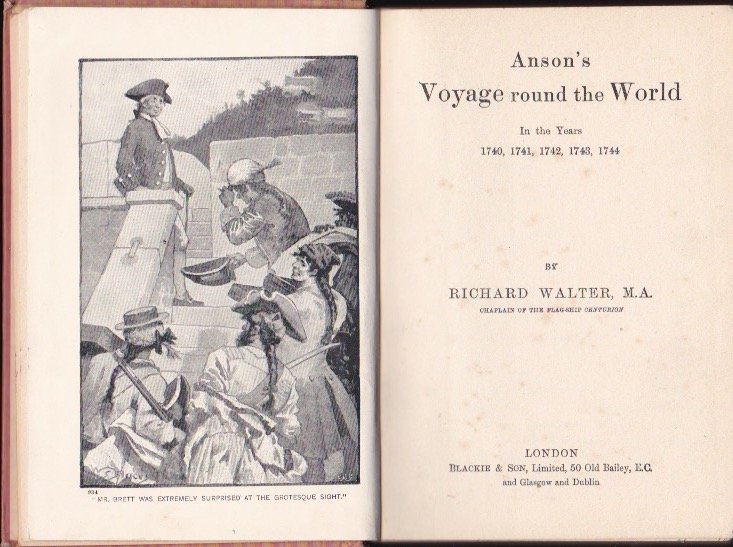
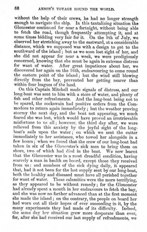
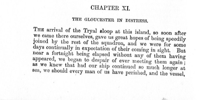
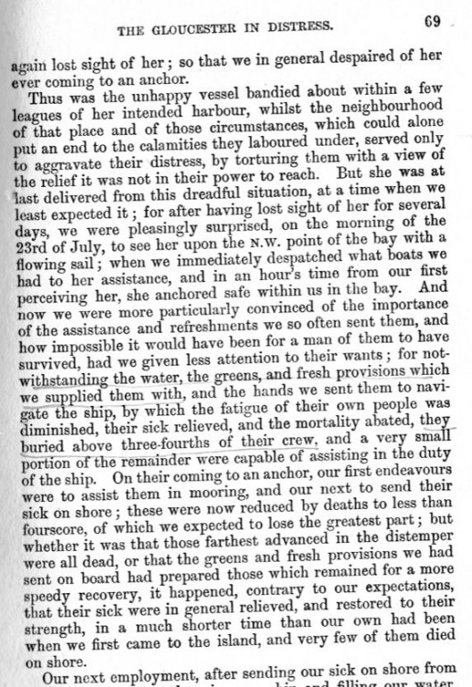
Today I have a fortunate distraction. I once owned a cherished book that over the years I read and reread on many occasions. About 15 years ago it disappeared and despite looking for it many times I never found it. I assumed that I had loaned it to someone and that it had not been returned. Today while looking for something else it turned up - hiding in plain view on the top shelf of one of our bookshelves. I was so pleased to find it that I started to read it once again. The book is old and somewhat tattered. Here it is:- It is difficult to see but it is Anson's Voyage Around the World - in the years 1740,1741,1742,1743,1744 In 2 days time the book will have its 112th birthday as attested by the script on the inside front cover:- The book is a first hand account of the voyage and purports to have been written By Richard Walter M.A. Chaplain of HMS Centurion. It is however believed that Walter was the editor and that Anson himself the writer. Within the book are many amazing accounts of the voyage but none for me is more poignant than the story of "The Gloucester in Distress" The narrative commences after the squadron had been scattered by a great storm while rounding Cape Horn. The prearranged assembly point in the event of such an event was Juan Fernandez island in the Pacific. HMS Centurion and the Tyral sloop arrived at the rendezvous in very poor shape and anchored to recover and await the remainder of the squadron. Here is the story of the Gloucesters arrival, I hope you enjoy the account:-


-
Mark - Yes - and the distance across the spars make it 30% longer. It will need quite a big display stand. John - good to hear from you again - as I get older my skill improves and my hands and eyes decline. It will be interesting to see how the balance of capability pans out.
-
Michael / Wefalck One of the benefits of creating the bulwarks as part of the hull planking is that the former for the shape of the bulwark is already created as part of the frame. Michael - your suggestion is how I did it when I built Altair and it is a good option if I can get the bulwark profile right. Wefalck - sounds interesting but I'd worry a little about differential expansion between the wood and brass over the 48" of hull length. My concern would be that the thin brass of the bulwark might ripple because of the constraint of the hull attachment and / or a crack would open up along the seam over time. However if other methods fail I may come back to it. I'm thinking of another option which is a bit unconventional and as yet I'm not too confident about it - i will worry about it a bit longer and maybe do a bit of experimenting before I decide between the 3 options.
-
Very good, I hope he gets some safety glasses as a late birthday gift?
-
Michael - probably didn't make that clear. First step will be to part off the frames at the building board level - either by laying a saw flat to the board and starting at one end progressively sawing through the frame stand offs - or alternatively plunging into the frame stand offs using the oscillating multi tool. I have already pre cut the frames at deck level - as per next photo. Once the frames are separated from the building board I will cut across the pre cut vertical slots using a small slitting saw mounted in the craft drill. I'll then cut the residual stub back level with the deck. I need to sort out a plan for planking the bulwark as it has no above deck frames to support it( just steel bracing rods). I think it will be a bit of a challenge! Wefalck, You agree with my wife. She came into the workshop with a cup of tea, took one look and made disapproving noises about eventual display options.


-
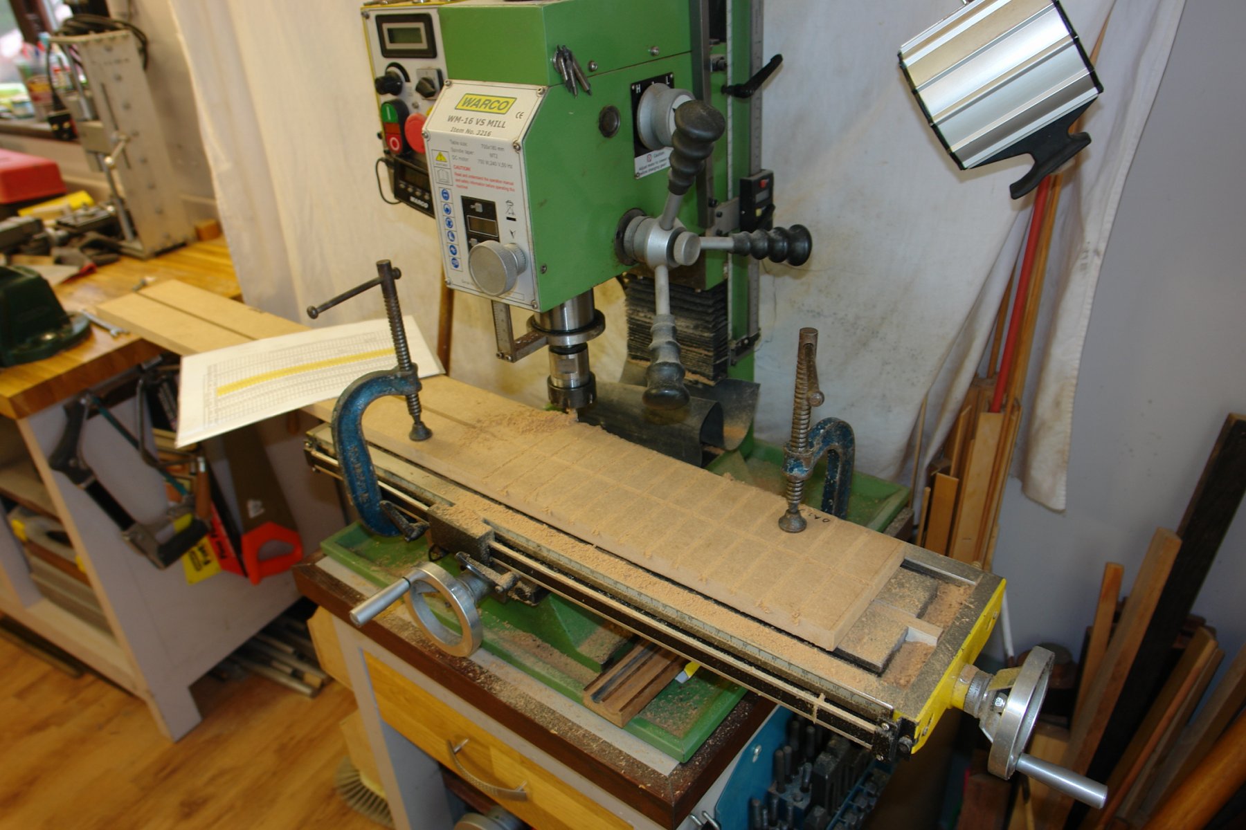
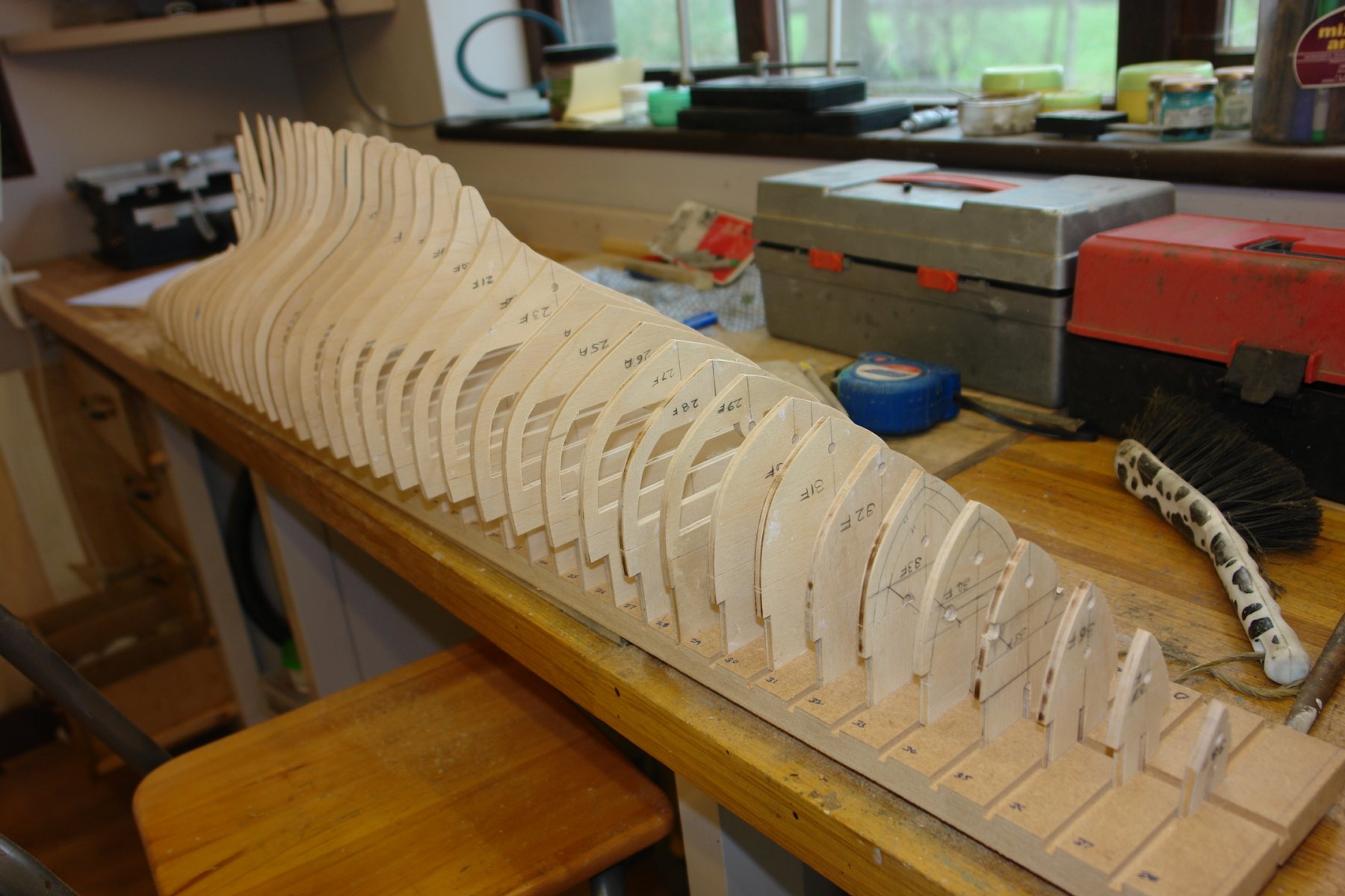
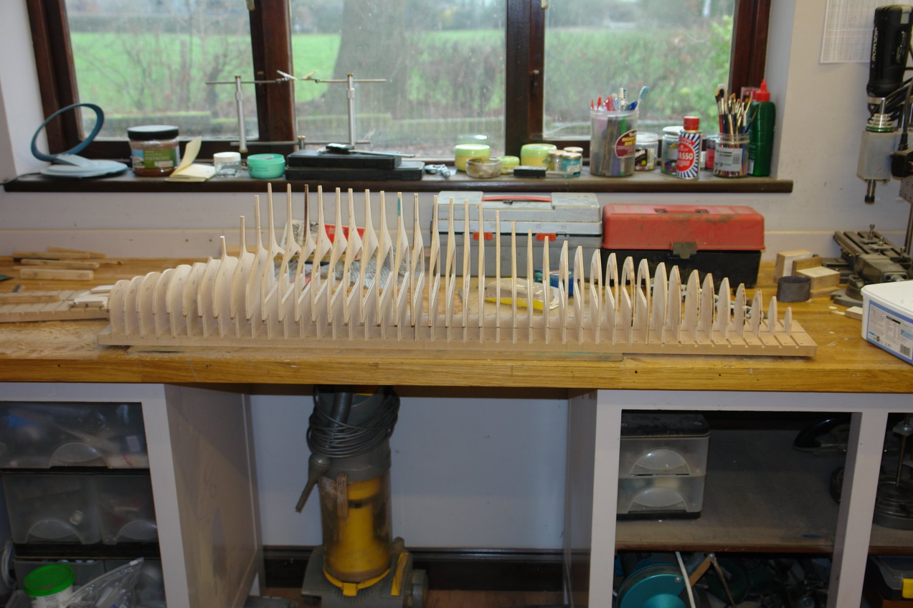
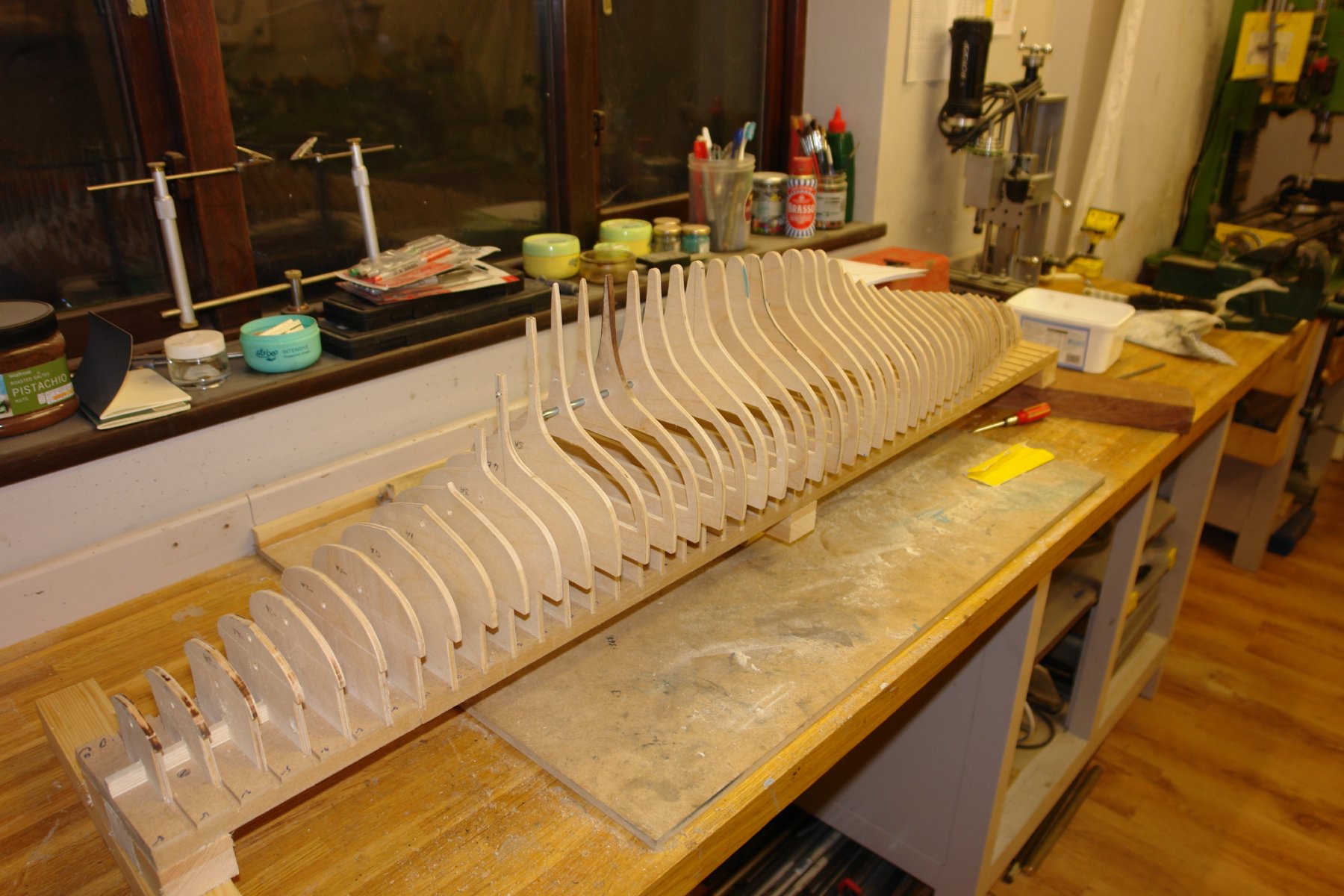
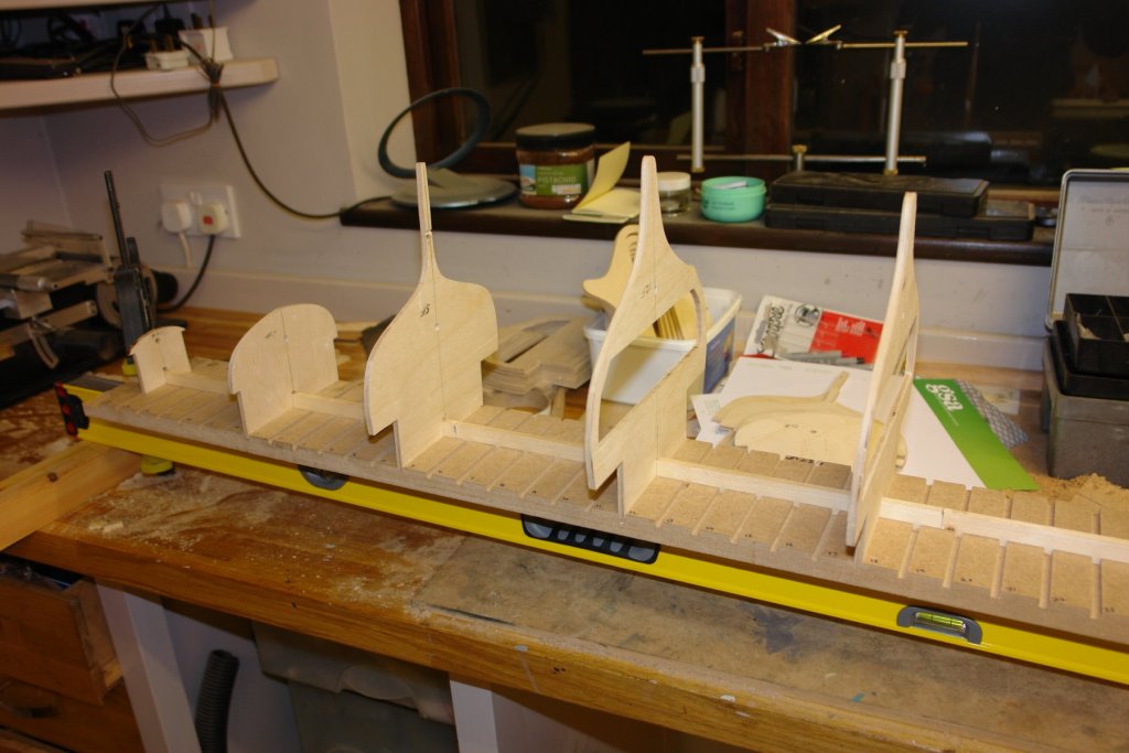
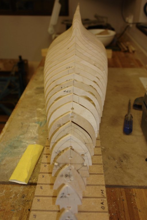
I made the building board. I purposely made it quite narrow at 5 inch to make handling during planking somewhat easier. The primary element is a 54" x 5" x 3/4" piece of MDF. Unfortunately the longest piece I had was 48" so it is actually 2 pieces. After cutting the MDF I cut a 6mm wide by 6mm deep slot down the centre on both sides using the router. I then took the MDF to the mill to cut transverse slots (5.5mm wide by 6mm deep) at the pitch of the frame spacing (as per previously posted data sheet). The mill table only has a 18" travel and so I needed to move the board progressively along it. To do this I set up location pins in the table "T" slot. These pins located in 6mm slot on the revers side of the board. The board was therefore able to move along the bed without losing its transverse location. Having slotted the board it was difficult to resist the urge place the frames in the slots ------- I failed to resist the urge. The central location up-stand wasn't in place at this stage and you can see that the frames are not well aligned. I took all the frames off and attached a very straight piece of 2" x 1.75" pine to the reverse side of the MDF to stabilise it. I then clamped the reinforced building board to a 72" spirit level to keep it straight while I glued the up-stand in place and then started to dry fit the frames again. This time the alignment was more pleasing. Tomorrow I will start gluing the frames in place and fitting the keel pieces.


-
Hmmm! very observant Michael. It spent many years holding a toilet roll in my daughters flat. It is going up in the world.
-
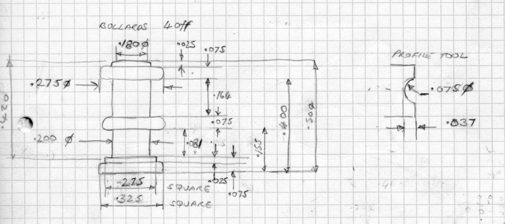
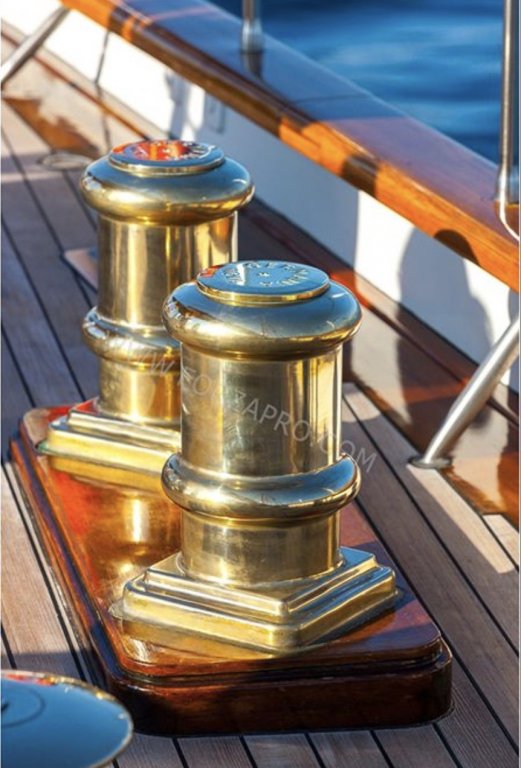
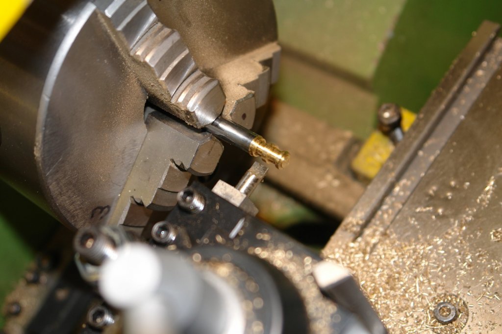
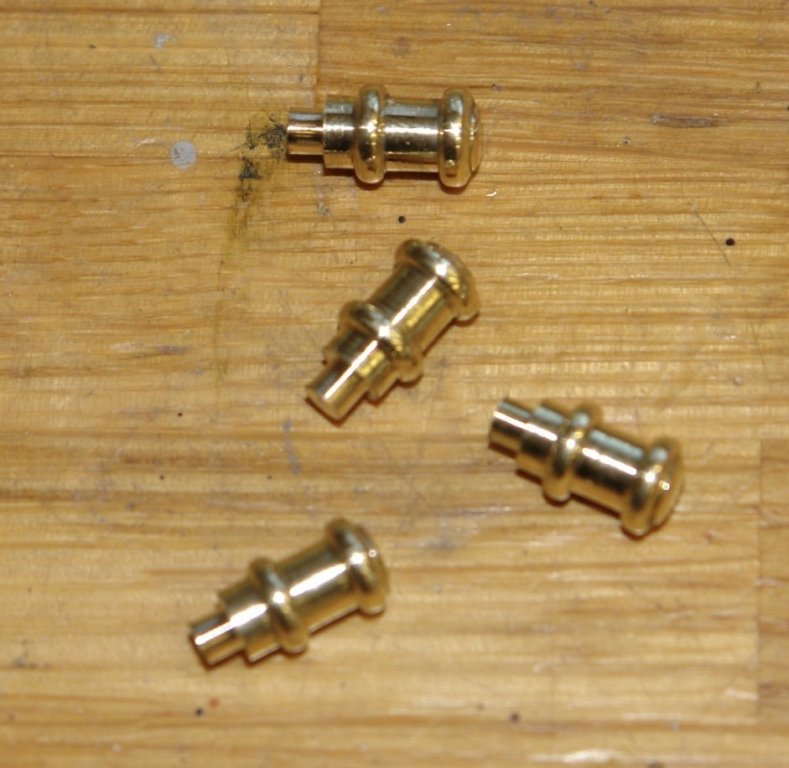
Thank you Paul - hopefully within a few days it will look much more like a hull. Another small diversion - Bollards! I didn't have a lot of time so I did a quick bit of turning. Germania has a nice pair of mooring bollards. Towards the stern - located both port and starboard. I dimensioned them up using the plank method described previously. I made myself a small profile tool to the dimensions shown in the sketch. Soon I had all 4 of the circular elements. I will make the square bases separately and solder them on.
-
Nice work Michael. May be better to fit hearing aid after playing with grandchildren. Or maybe they are beyond the noisey stage?
-
Tony, Just found your build and enjoyed your detailed descriptions. I look forward to reading more.
- 124 replies
-
- 2
-

-
- longboat
- Chaloupe Armee En Guerre
- (and 1 more)
-
Druxey. The more I practices the luckier I gets. Maybe its luck rather than organisation.
-
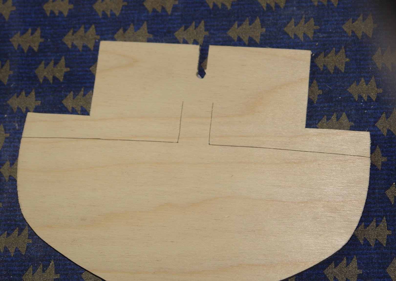
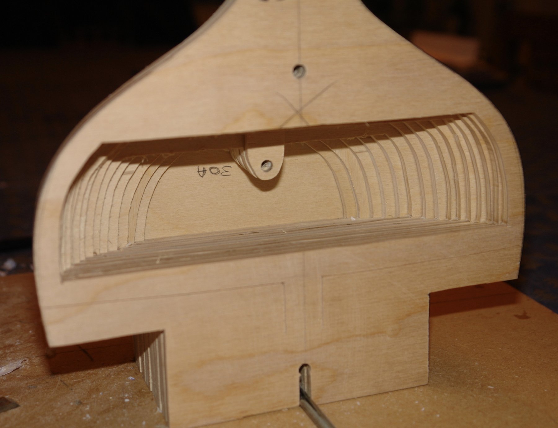
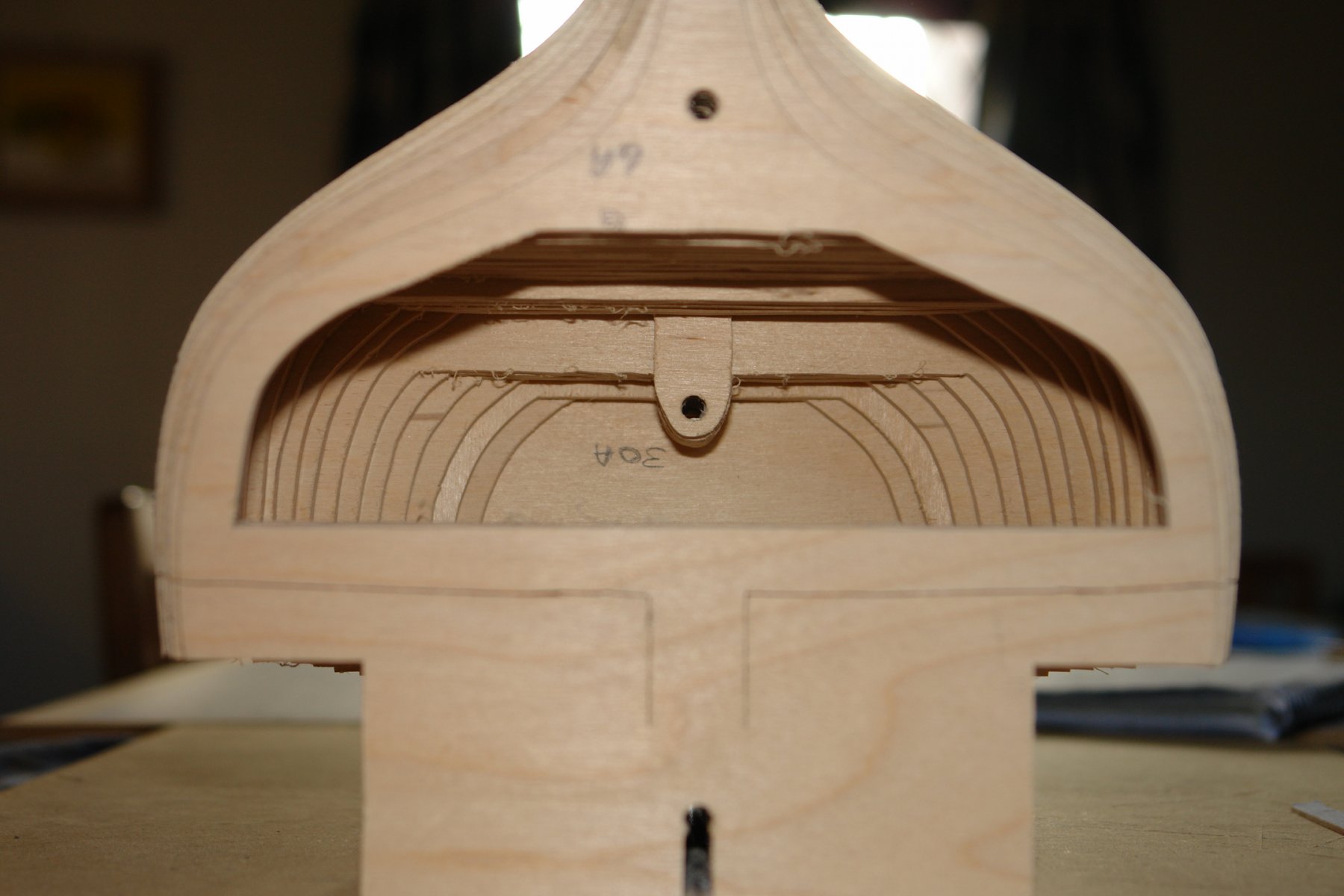
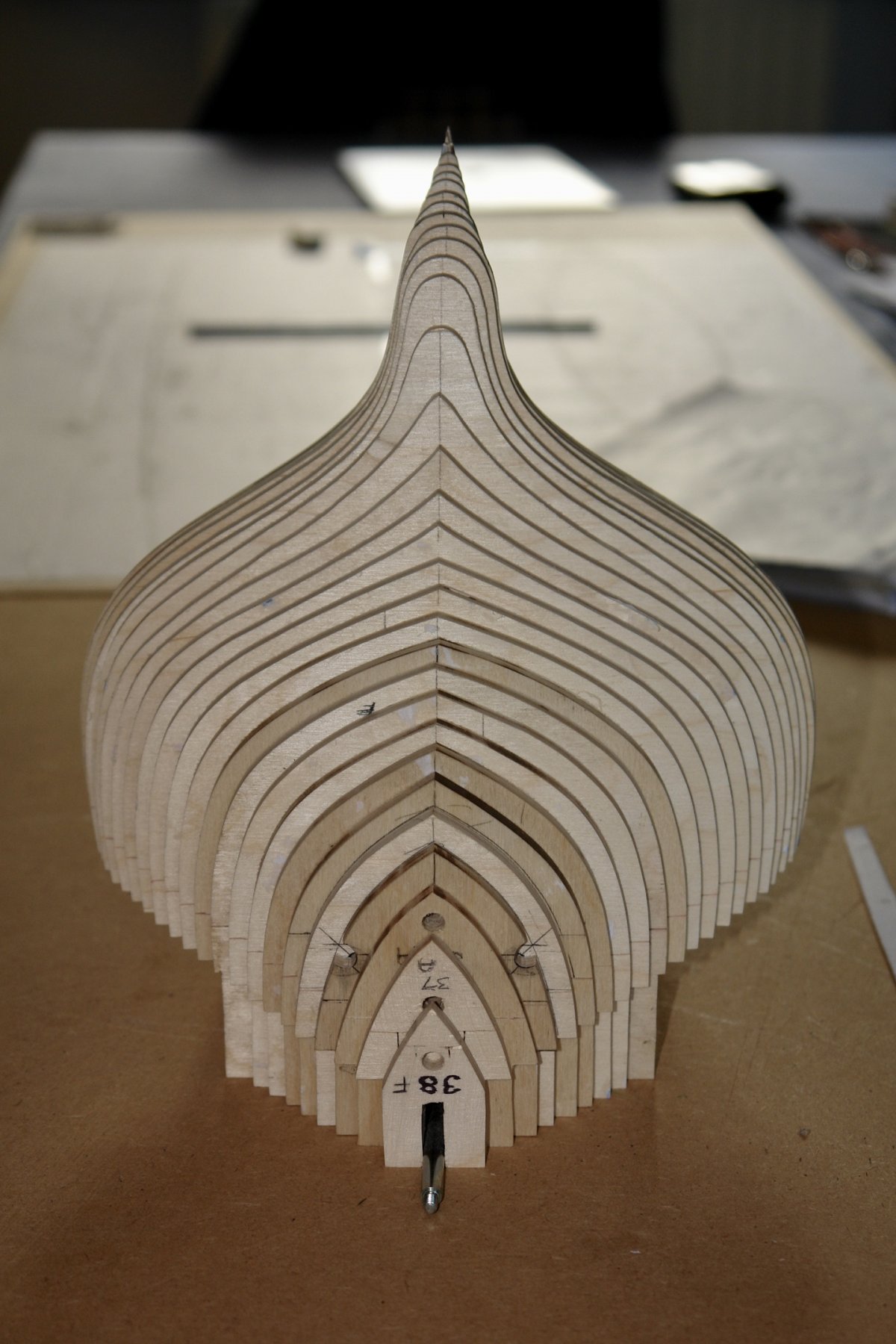
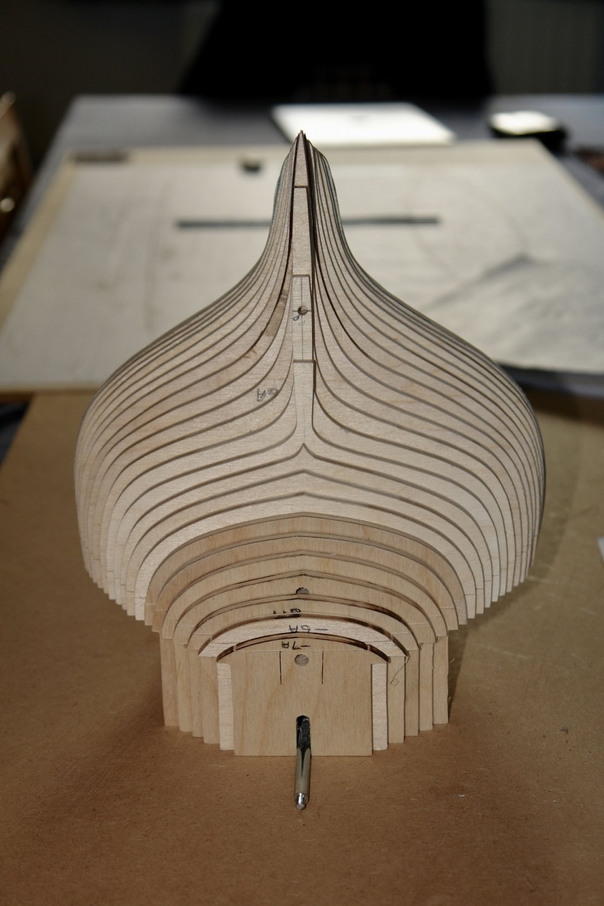
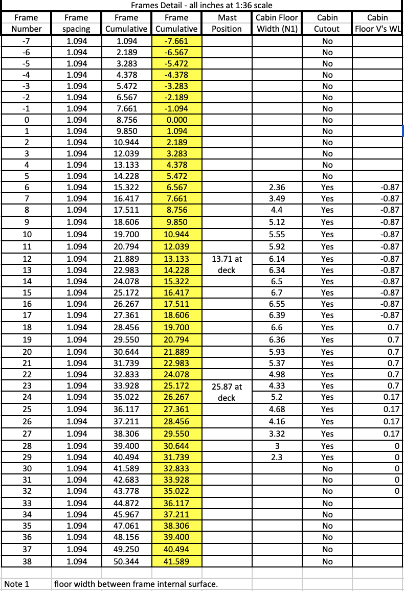
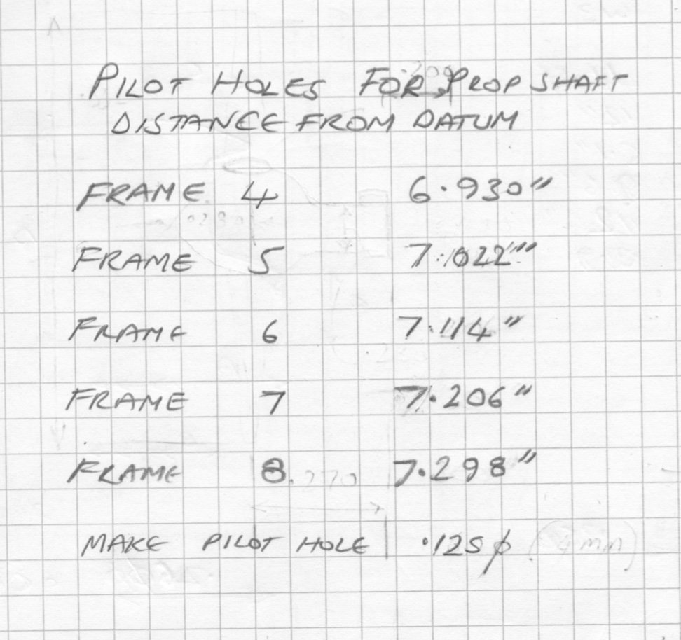
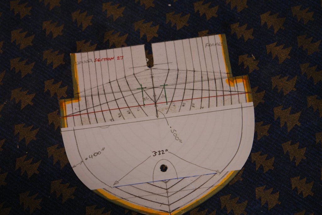
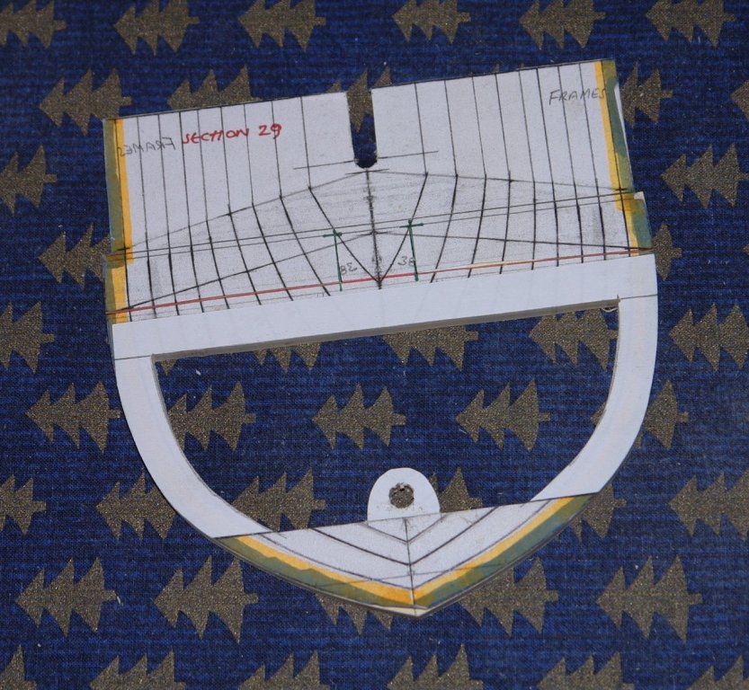
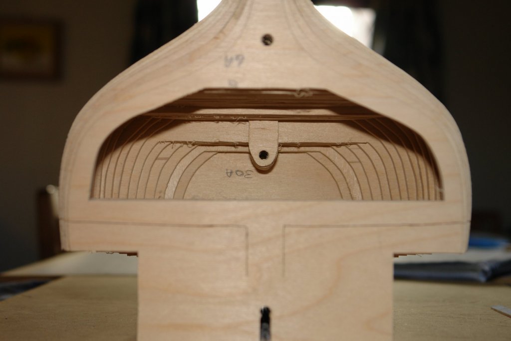
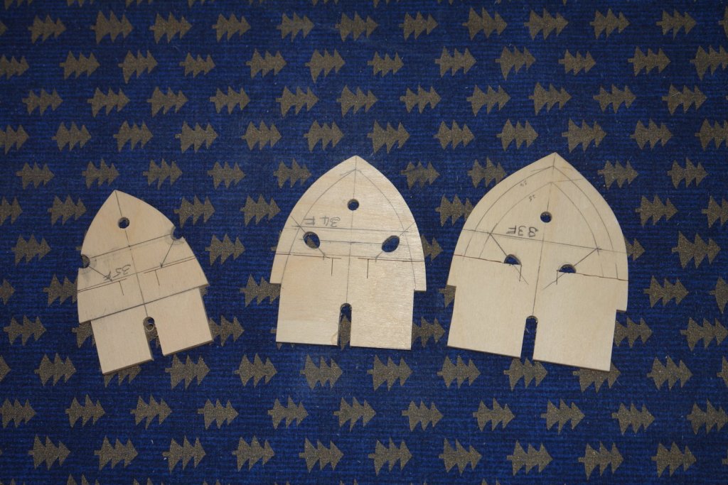
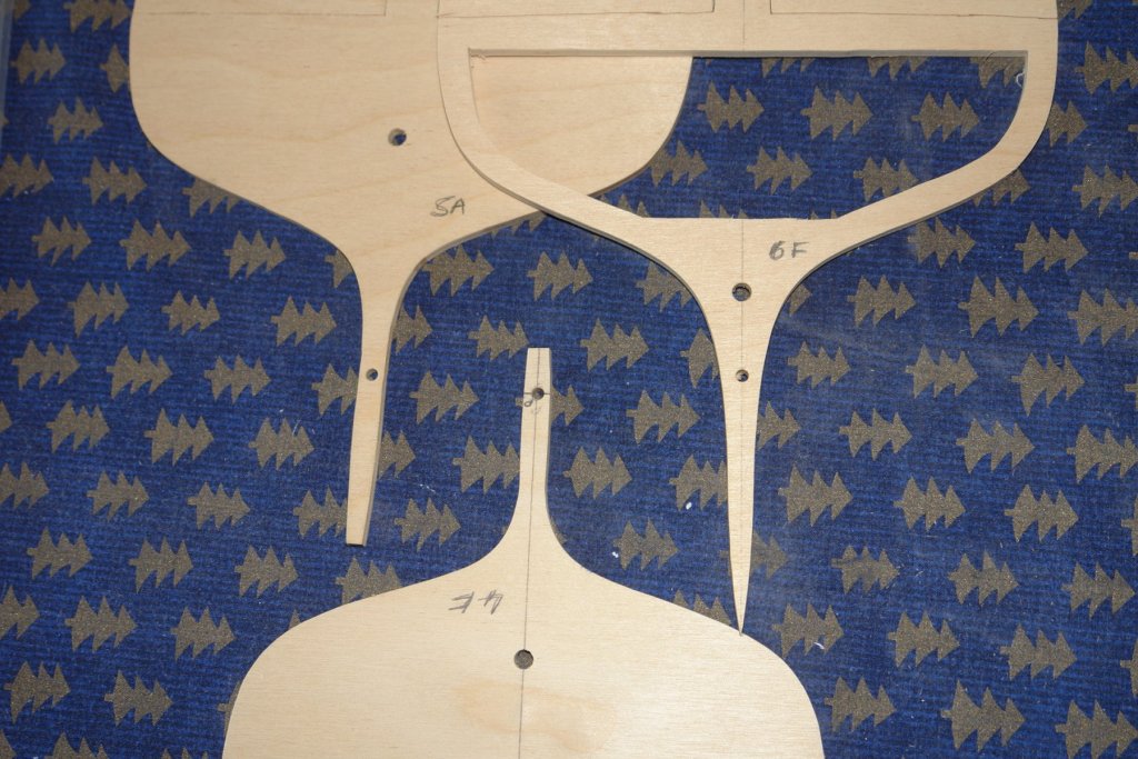
And so back to the scroll saw. I'm not planning to kit out the cabin as it wont be possible to see it. However what I do need to do is create a cabin floor so that the view through skylights and down the hatches looks realistic. While I was at it I decided to put the floors in at their correct levels. The cabin floor actually has 3 levels - stepping up progressively towards the bow. I started a data sheet because I am apt to forget critical dimensions. Soon I will be on the making the building board so I recorded the frame positions. While I was at it I also recorded:- 1 - positions of the masts. 2 - the cabin floor levels 3 - where I planned to cut out the frames for the cabin floor 4 - the width of the cabin floor at the various frames. I expect I will expand the data sheet as the build proceeds. I marked out the cabin cut outs on the relevant frames - I found that overlaying the frame lines with another piece of paper reduced the confusion and made the task of cutting the correct line somewhat easier.. I made sure that I didn't remove the frame alignment holes at this stage. Much time then passed quickly:- The cabin floor levels can be clearly seen, albeit up side down. I remember previous experiences of trying to drill and file hawsepipe holes through deck, hull and frames and thought I'd make it easier by pre-cutting oversized holes in the relevant frames (33, 34 and 35). I also took the opportunity of drilling the pilot holes for the prop shaft. These are the smaller holes in frames 4 5 and 6 below - I also predrilled frames 7 and 8. The prop shaft hole positions are as follows:- I'll make a start on the building board next.


-
Valeriy, Very Nice work. I think I would have chickened out and made them from preformed channel.
-
ancre La Salamandre by tadheus - 1:24
KeithAug replied to tadheus's topic in - Build logs for subjects built 1751 - 1800
Great work Pawel. What metal is the strap of the hinge made from? -
Wefalck I only used the hex bar for the 2 larger winches - about 25mm of it. The across flats dimension of the hex was just over what I needed (about .61" and I needed 0.54" ) while my next available round size was 3/4 inch. I had more .610" hex than .750" round in my metal store so chose to use it. John - thank you.
-
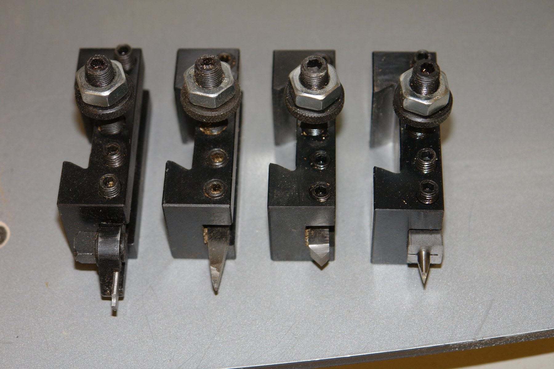
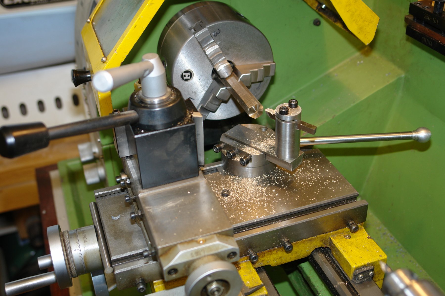
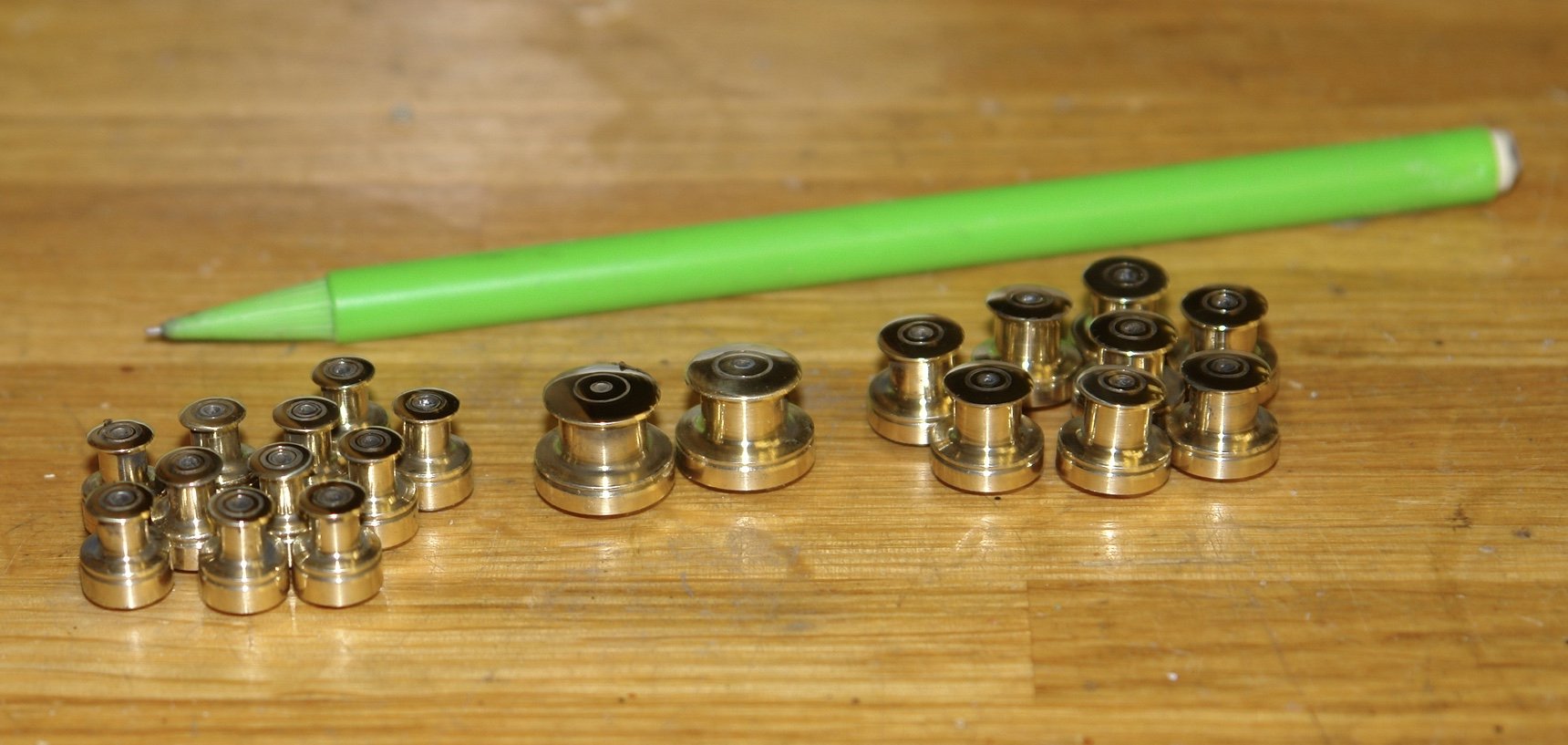
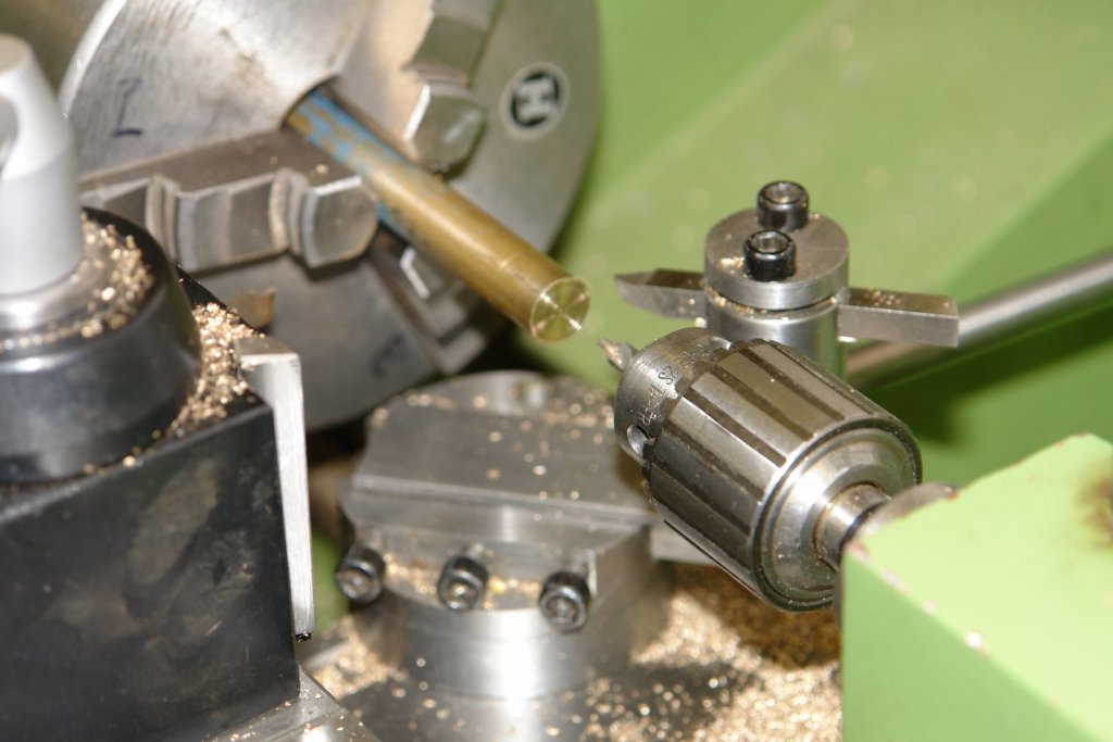
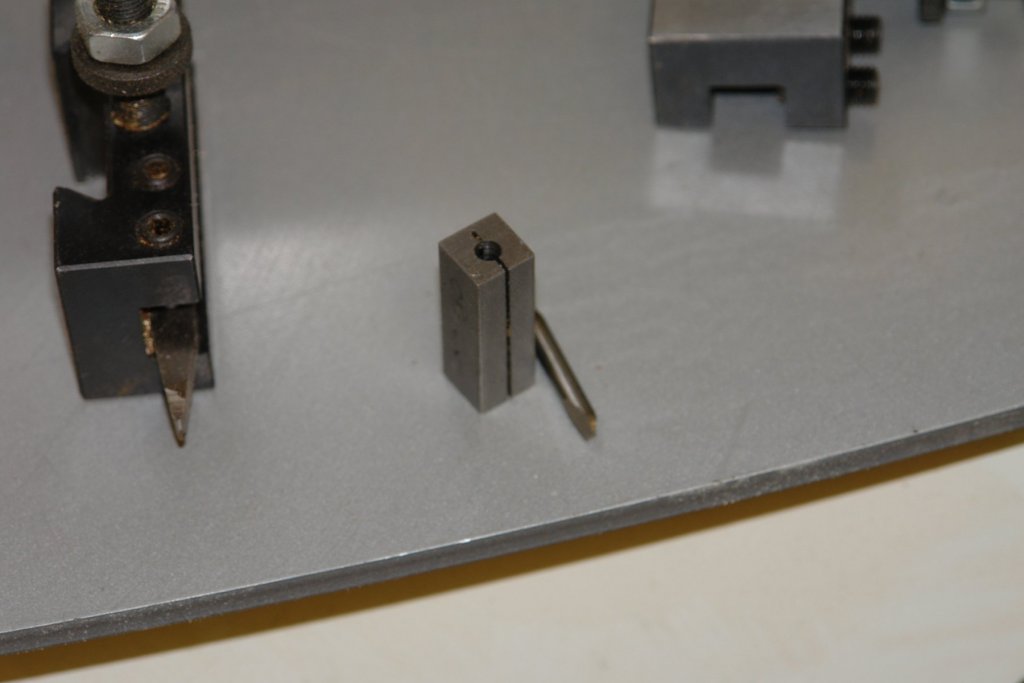
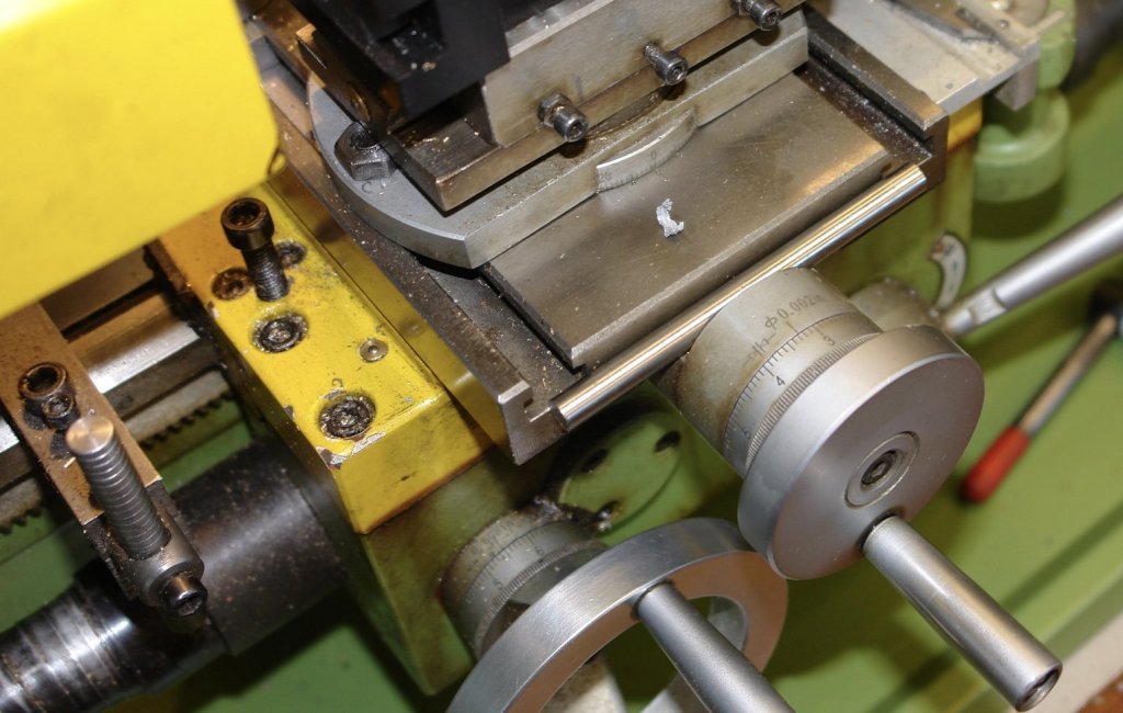
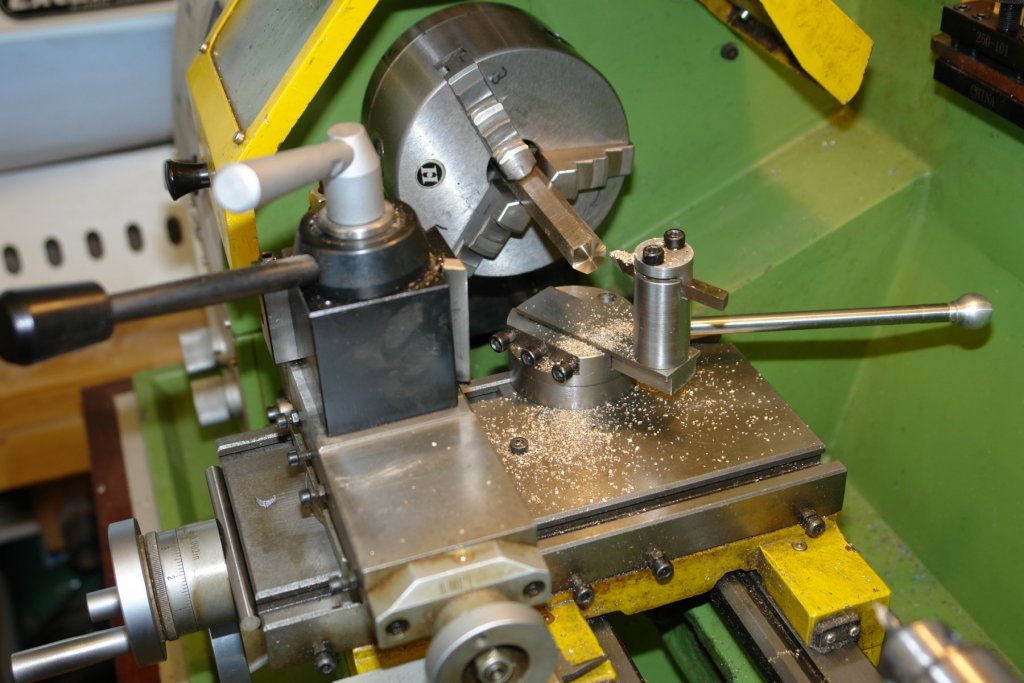
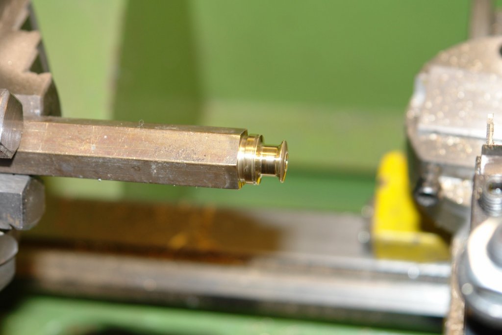
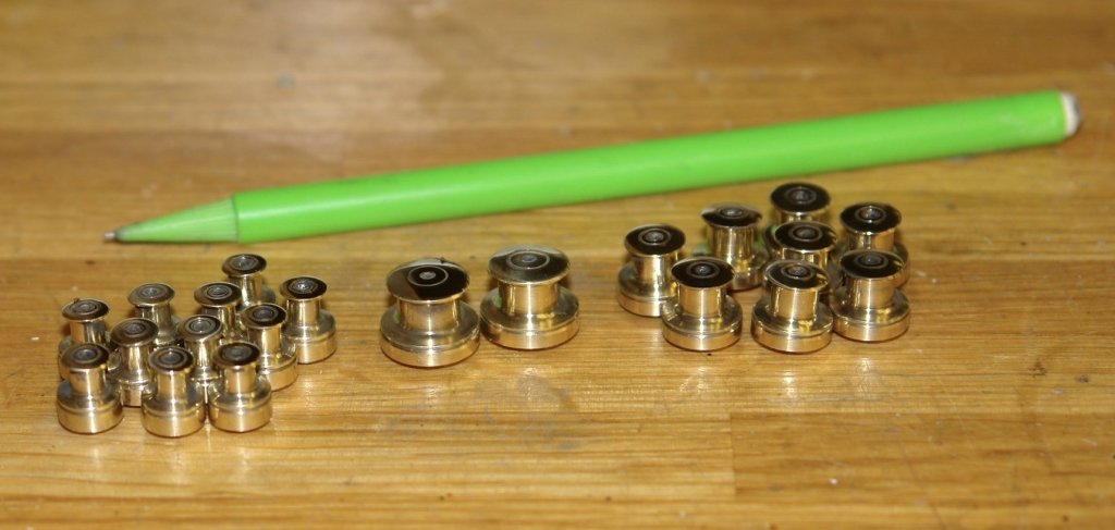
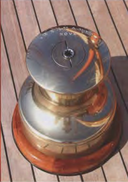
I couldn't resist the urge to make the winches. It was the first time in a long time I had had the benefit of a production run. I do like solving the problem of how to make identical components efficiently. By the time I had finished I could make a winch in under 5 minutes. I will try to explain. Because the tops of the winches are spherical I needed the ball turning tool. I didn't however want to mount and demount the tool post / ball turner for every winch. So I set the ball turner up on the rear of the cross slide while leaving the tool post in place. I also needed to maintain access to the tail stock for drilling. I set the ball turner to .800" radius and then mounted it loosely on the cross slide. It was preferable to have the ball turner set to stops so that I could always get it back to exactly the same position for each winch. The lathe bed has a standard clamp type stop (bottom left in the next photo). I don't have a cross slide stop but I do have a trick. In the previous photo you can see that the cross slide hand wheel stands proud of the boss connecting it to the slide. The horizontal bar behind the hand wheel isn't part of the lathe, it is a piece of tool steel that is restricting the outward travel of the slide, thus creating a stop. I wound the saddle and cross slide against their respective stops and then positioned the ball turner on the centre line of the chuck and clamped it down - ensuring that returning to the stops meant that the ball turner was set up perfectly for the next ball turning operation (i.e. the next winch). I mounted all 4 tools that I needed in tool holders. I needed a very fine grooving tool so I made one from a broken 1/8 inch centre drill mounted in a home made slotted clamp. Having worked out the set up the first operation was to turn the spherical end. The sphere was turned on the back side of the lathe with the lathe running in reverse (At least it was when I remembered). Because the sphere turning operation was done against stops the position of the sphere was easily repeatable for all successive winches. I then machined the first winch in the conventional manner using measurements to check the dimensions. I did however note the axial (saddle) location and transverse (cross slide location) on the lathe dials for all the finishing cuts. I then generated the subsequent winches by duplicating the recorded dial settings with no measurement involved. Needless to say that I made sure that I never reset the hand wheel scales or changed the tool post rotation at any point. I had to do the recording of dial settings 3 times for the 3 different winch sizes. I made a fortunate mistake in that, for some reason, I made 9 of the medium sized winch. The fortunate part kicked in while using the polisher buffing wheel. It ripped the winch out of my hand and the initial impact on the bench was followed by a distant ping. At this point a micro worm hole popped into existence and devoured said winch, transporting effortlessly across the vastness of spacetime and into an infinite future of possibilities. I am comforted that in one of these possibilities a sentient being (named Keith) is working on his boat and wondering where he put that winch. Suddenly it materialises in front of him and my efforts are not in vain.


-
Hi Michael How thin do you need the leather to be? My wife has some very fine (and thin) leather gloves - would gloves be a potential source?
-
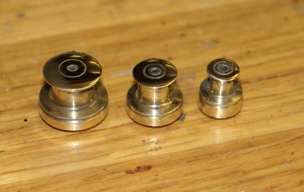
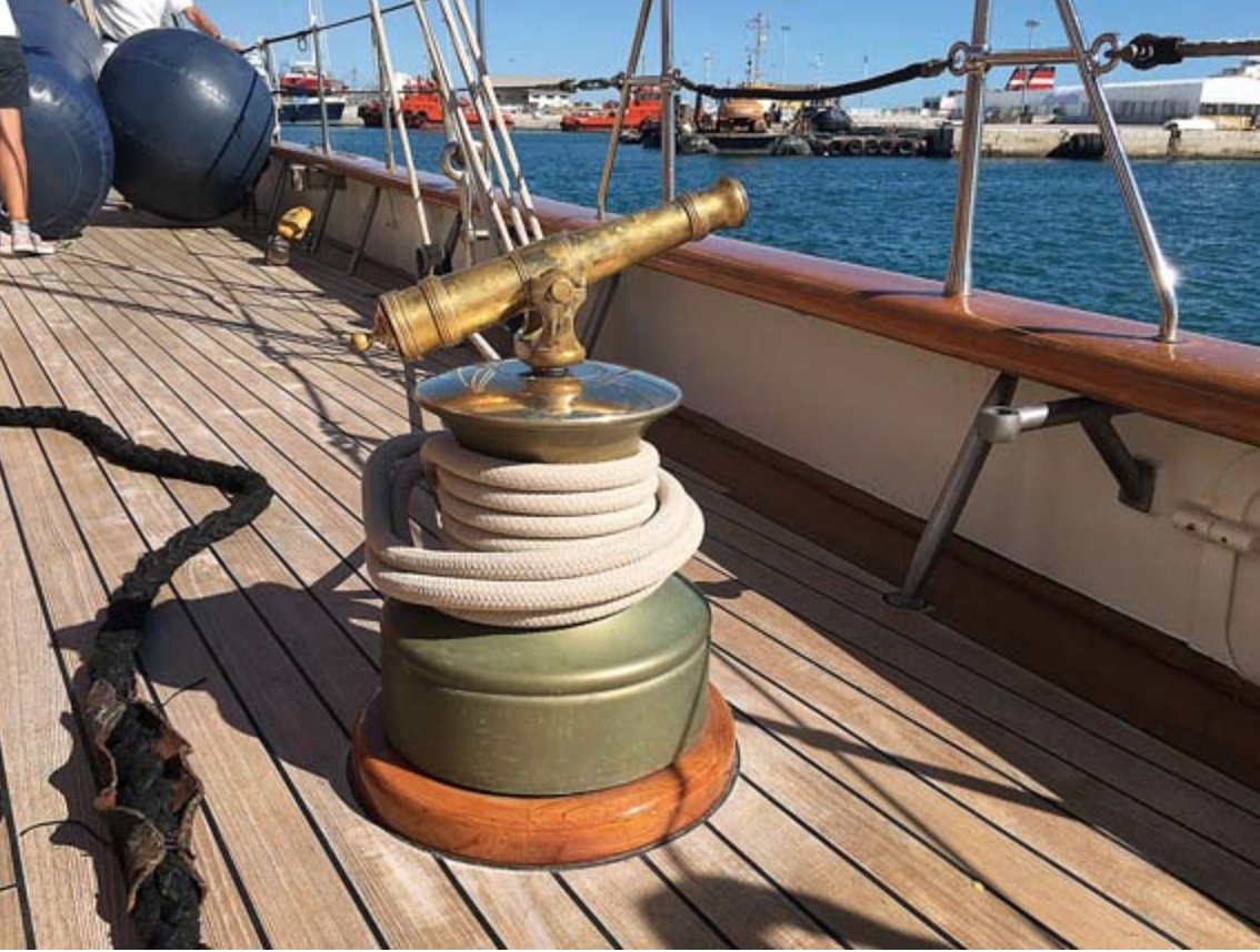
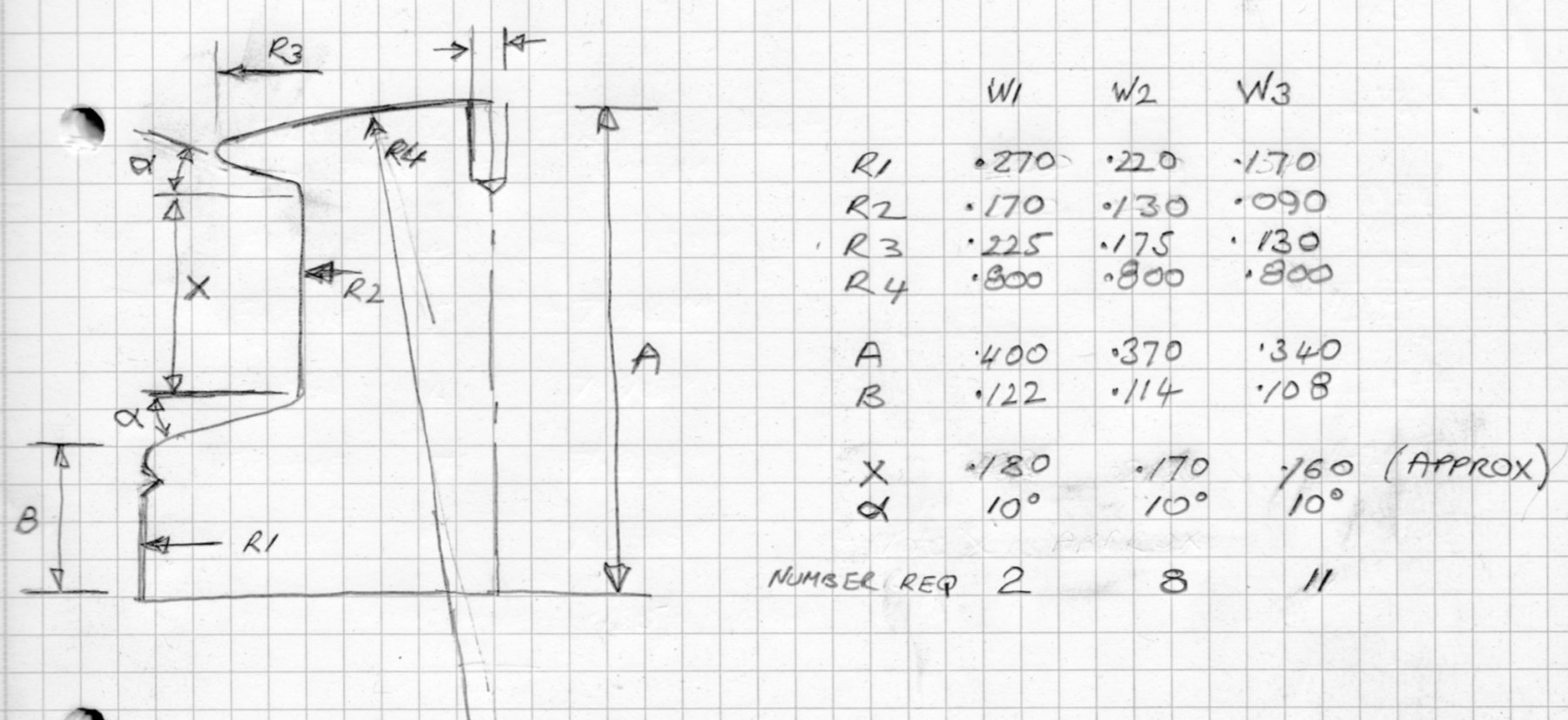
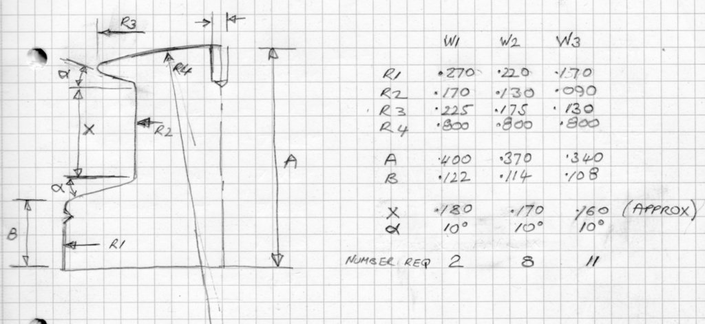
Today my resolve failed me. The workshop was cold and uninviting compared with the delights of the lounge and roaring wood burner. Will power fades with age!!!!! Anyway having made a start on sizing deck fittings I thought i could sit in my arm chair and complete sizing of the winches. Fortunately photographers and winches seem to attract one another like wasps and jam and I have many photos. I particularly like the starting gun version. Must make one like that. Germania has 3 sizes of winch. The good news is that the deck plan I have clearly identifies the positions of the different sizes - 2 large, 8 medium and 11 small - a total of 21 which seems to me to be more than ample for a craft of this size. Much measuring later and I have the size of all 3 versions. All dimensions in inches and at 1:36 scale. Tomorrow is committal day, I don't mean to an institution, although the kids might disagree. I mean committal to either Germania or Germania Nova. The winches are from Germania Nova and once I have knocked them out I don't think I will want to change track. I have cleaned off the lathe and the brass rods have been sorted. So tomorrow, bright and early, it will be time for turning. Note to self:- DON'T LIGHT THE WOOD BURNER.


-
Thomas, i visited the site but it does not carry much detail. Do there plans have a lot of detail and do they seem accurate? Thank you.
-
Wefalck, Thank you I will follow up your suggestions. In terms of which version I started off undecided. The availability of information however is swinging me to Nova. I will need to make the decision soon. Michael - thank you.
-
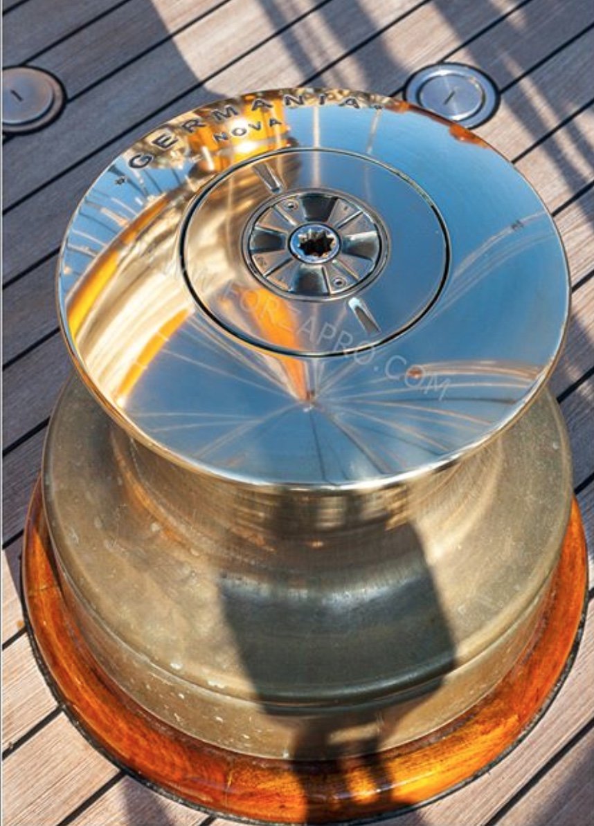
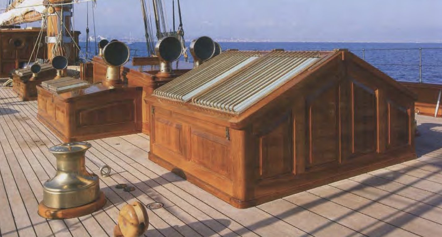
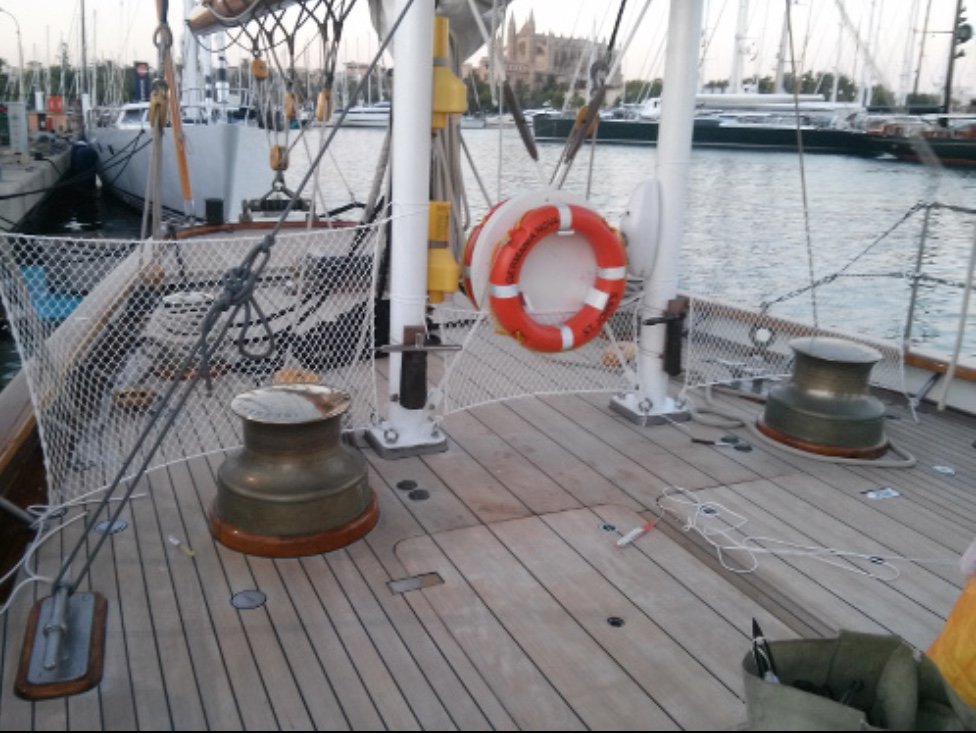
Thoughts on sizing deck features - the "PLANK" method. The deck is covered in fittings - cleats, bollards, winches etc., etc., none not which are detailed on the plans. I therefore have to develop a method of estimating their size from the many photographs I have. A feature of most of the photographs of fittings is that they usually have a section of the adjacent deck somewhere in shot and I figured that If I could size the width of the planks then I could (by comparison) size the fittings. So I used the following photograph and sized the planks as follows:- The skylight deck house, as measured on the plans is 71.6" wide. From the photograph the skylight is 9 of the wider planks wide. The wider planks are therefore 71.6/9 = 7.95" wide - call it 8". Comparing the wider and narrower planks the ratio of sizes is .320 to .840. By Calculation the narrower planks are 32/84 x 8= 3.047" - call it 3 inches. 8" and 3" seem sensible sizes for deck planks and I'm reassured that the sizing is reasonably accurate. Now to size the winch in the picture:- Its major diameter is about 4.5 narrow planks wide = 13.5" The diameter of the neck is 1/2 of the major diameter = 6.75" The diameter of the top flange is 3/4 of the major diameter = 10.125" The vertical dimensions need a bit more care in estimating as the perspective is a more significant factor. It's better to find a shot of the winch in the distance as the camera to deck angle is much reduced. Having done this the vertical dimensions can be obtained by comparison with the already sized diameters.