KeithAug
-
Posts
3,980 -
Joined
-
Last visited
Content Type
Profiles
Forums
Gallery
Events
Everything posted by KeithAug
-
 Eberhard. The prop was fitted when she was rebuilt prior to completion in 2009. I don't have any information on the original but clearly the design is not of 1901 vintage. As you say the original was probably 3 or 4 bladed.
 -
A pleasure to see your deck hatch work Mark.
-
Nice progress Raz. The steam pipes must have kept the cabin warm.
- 128 replies
-
- 3
-

-
- zulu
- sternwheeler
- (and 1 more)
-
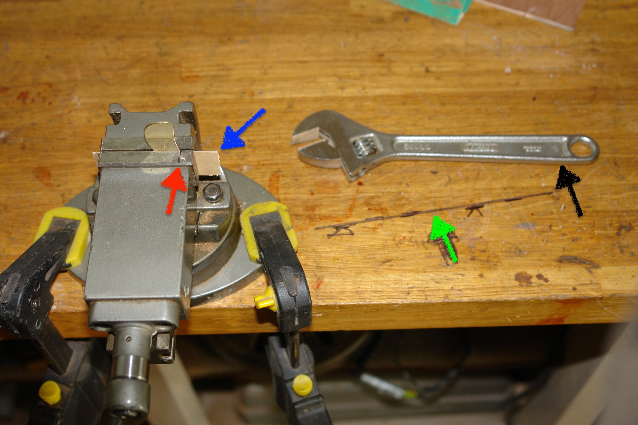
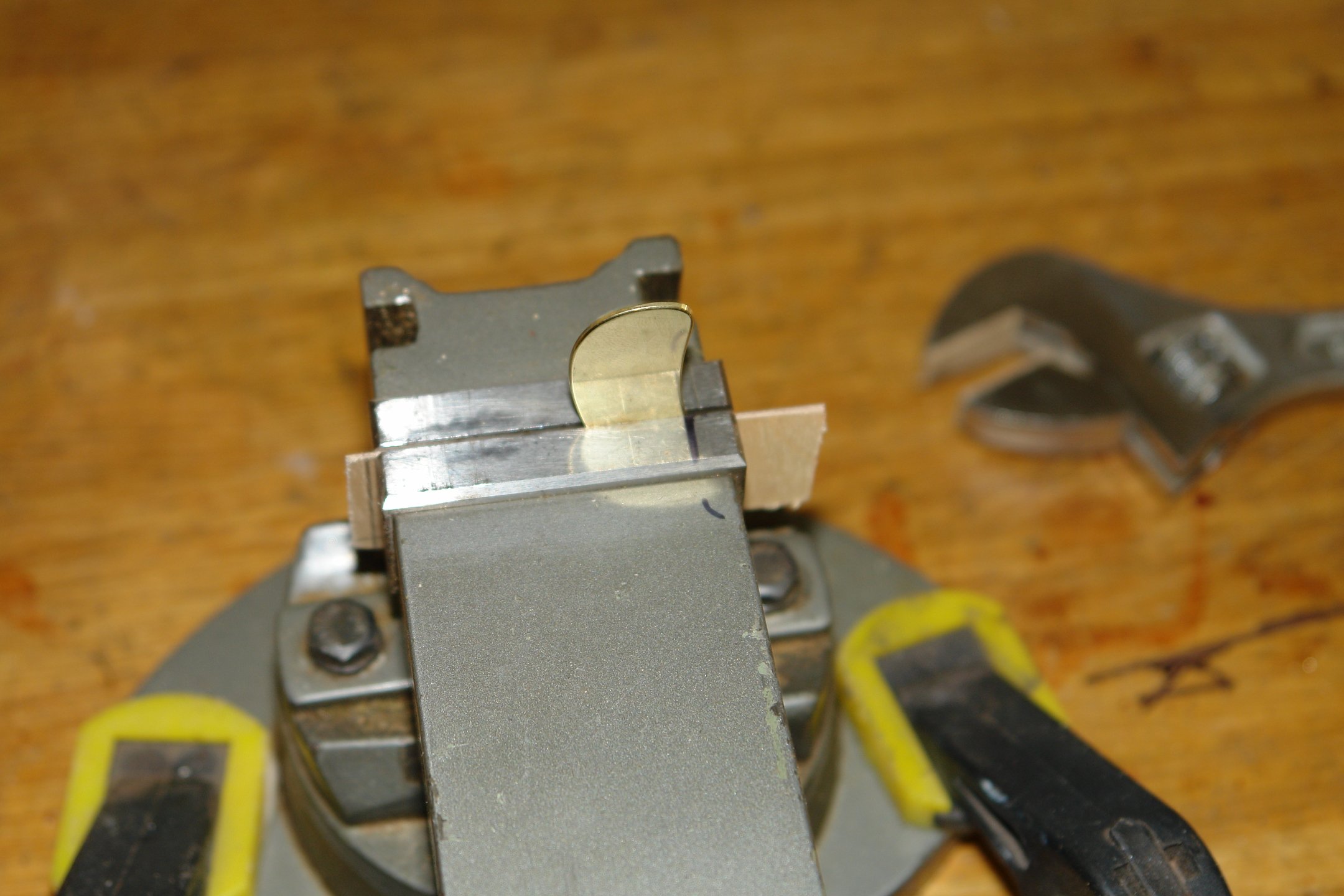
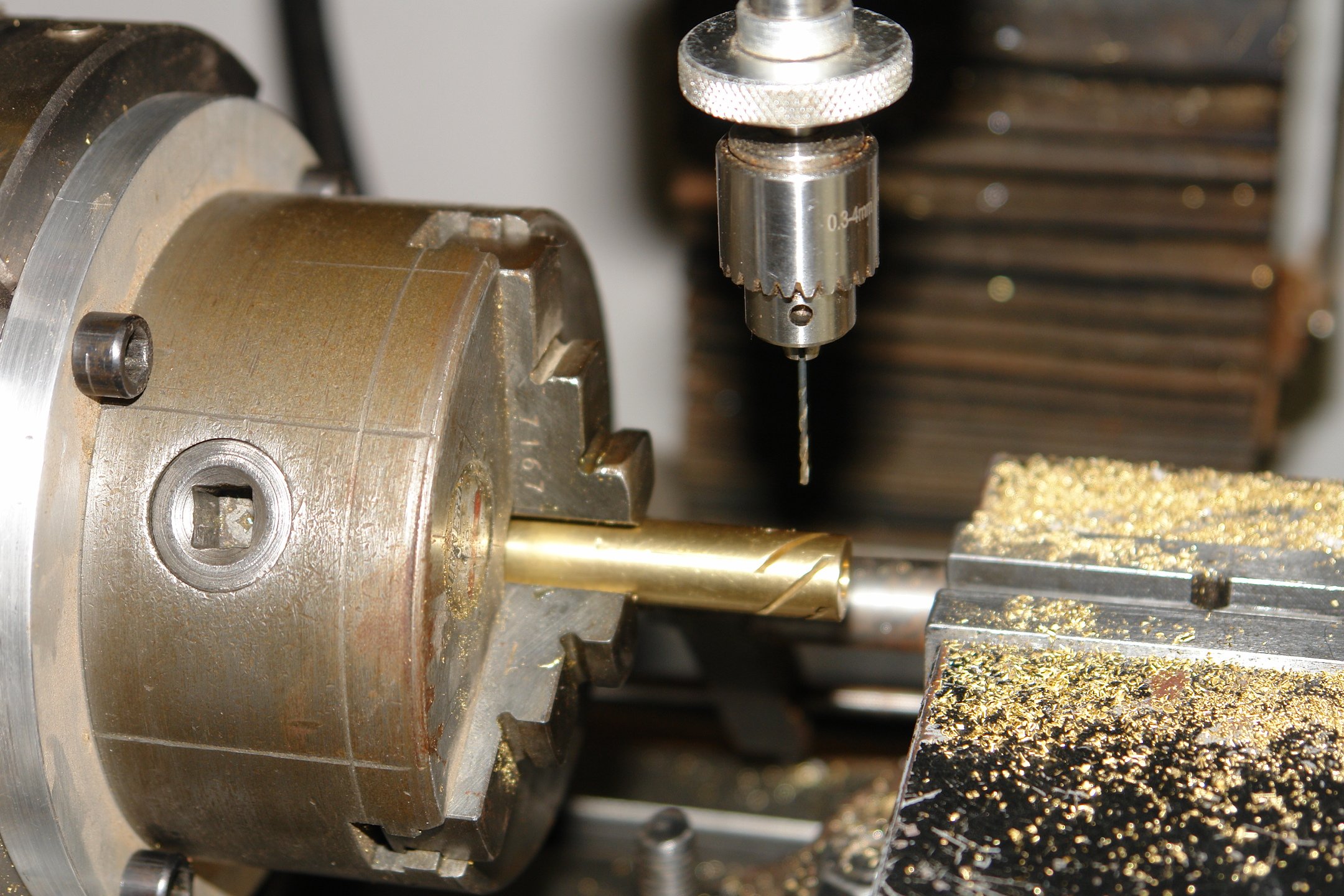
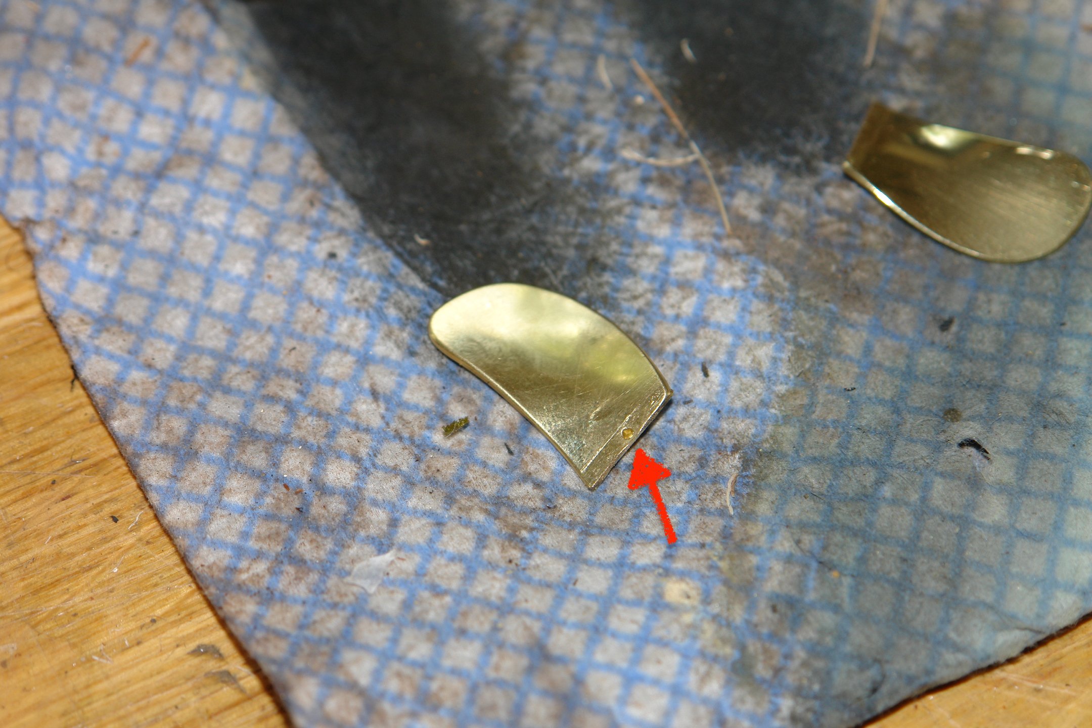
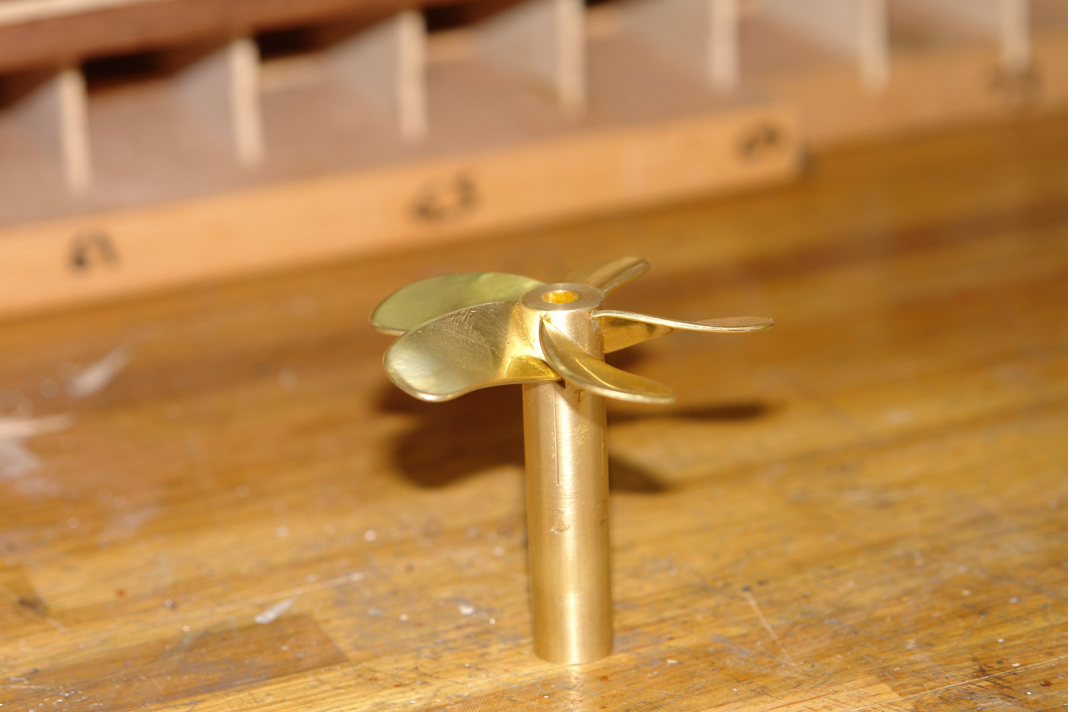
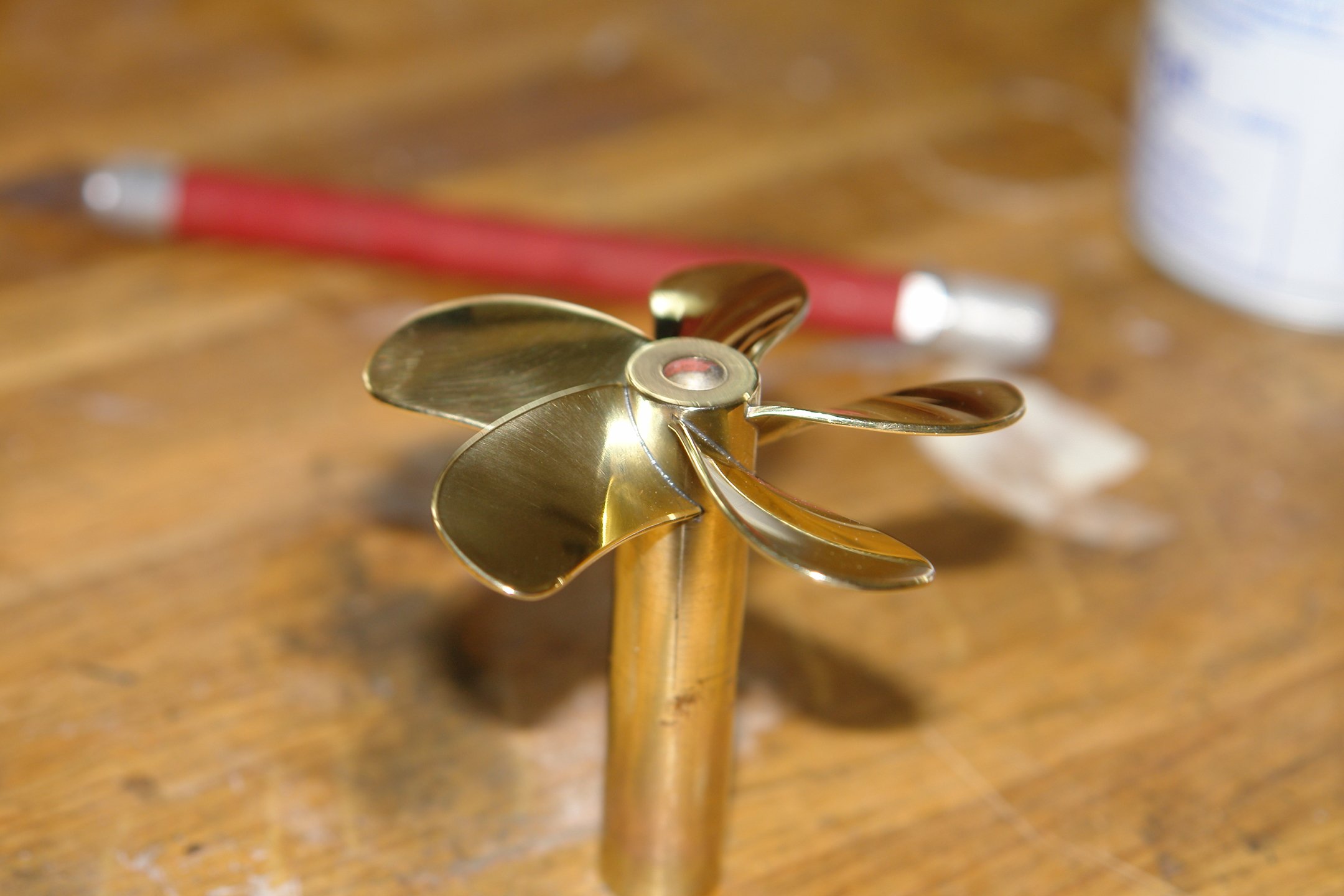
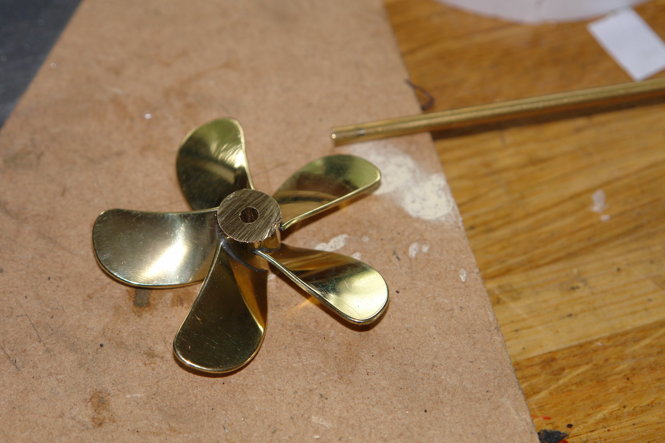
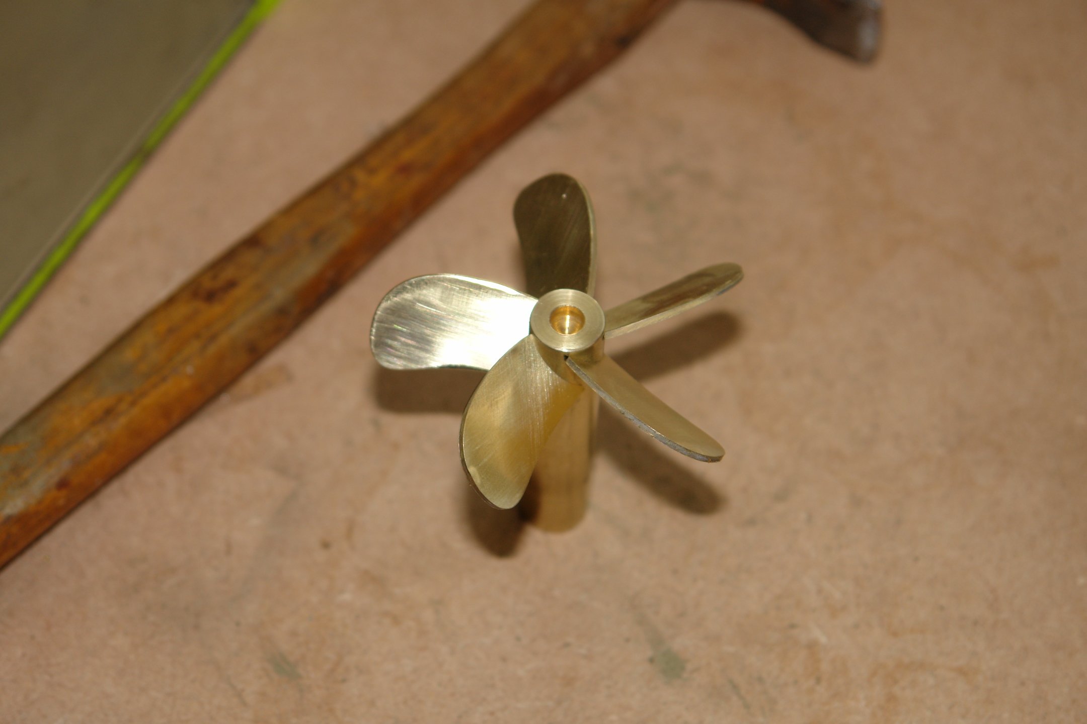
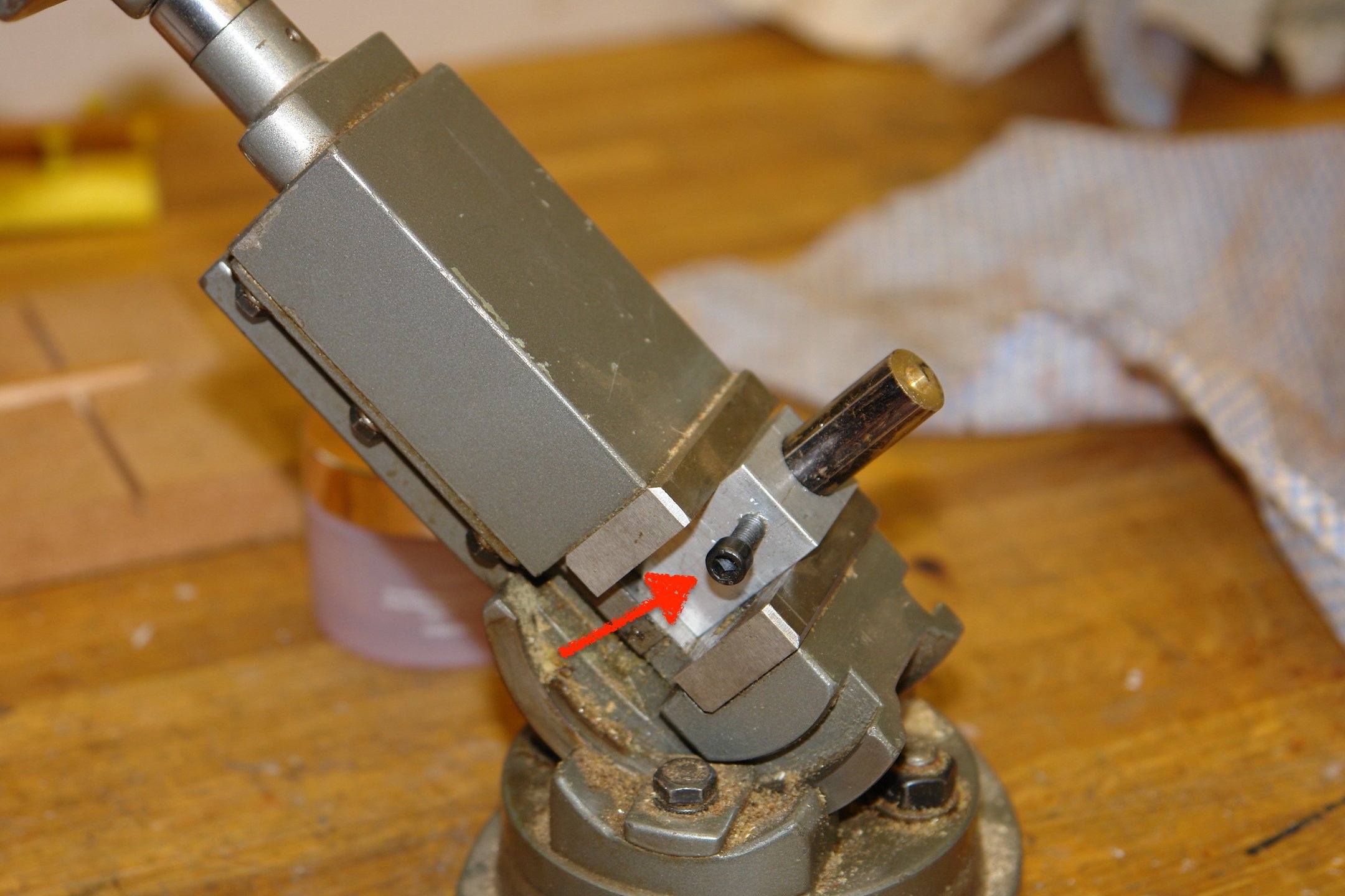
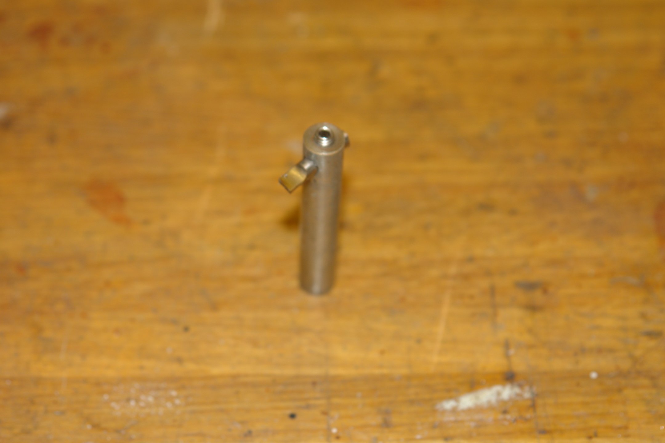
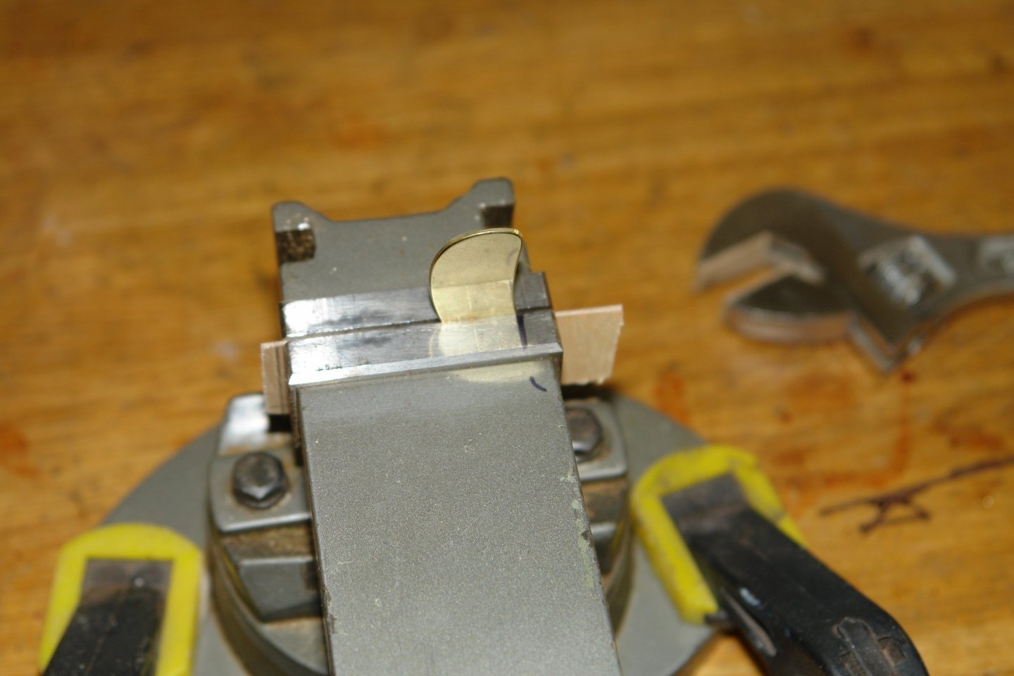
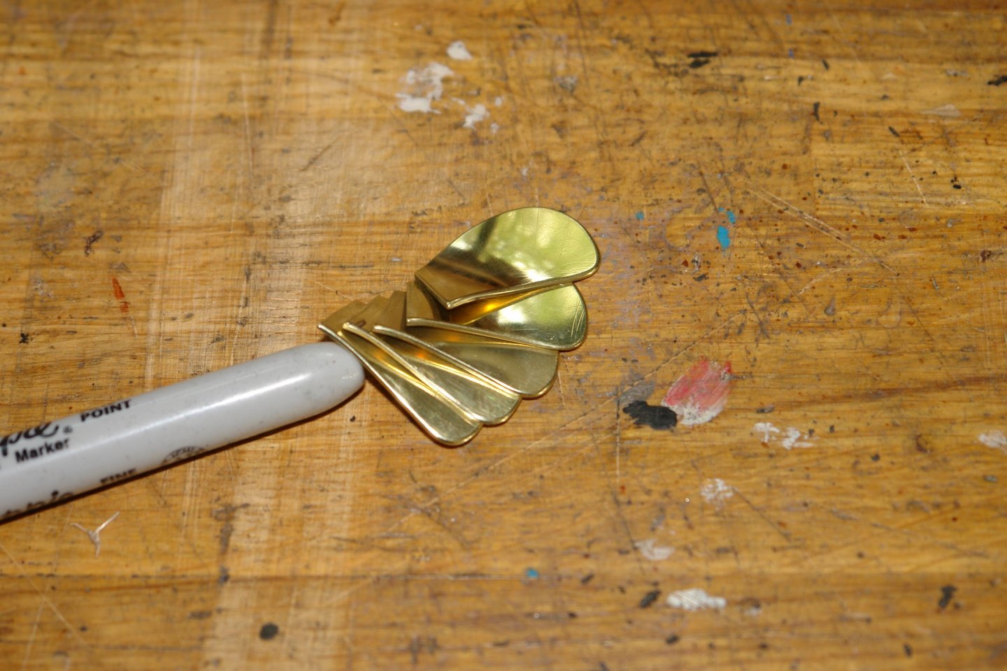
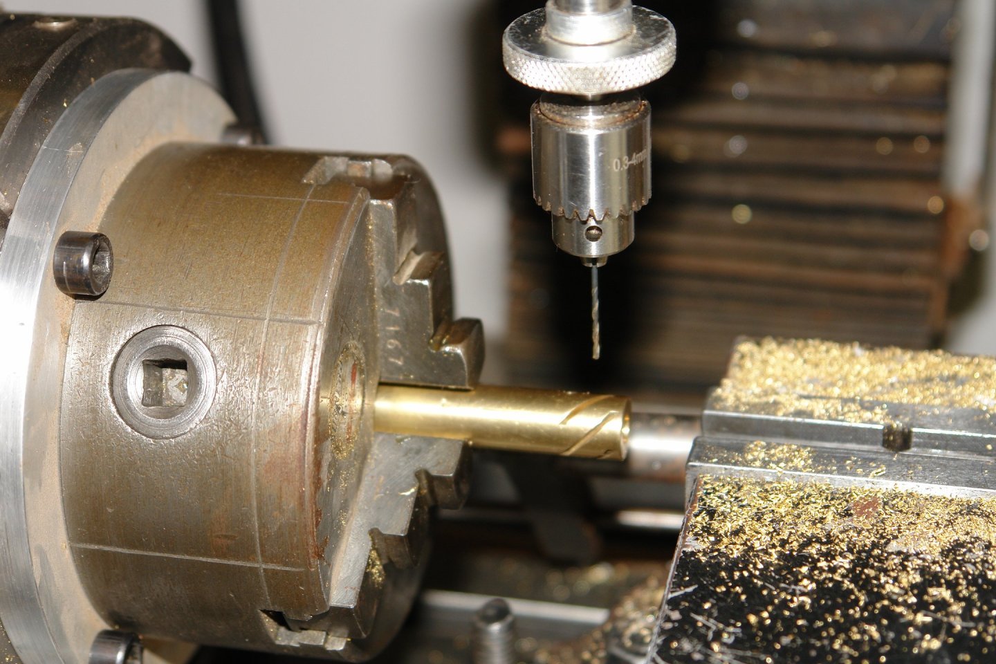
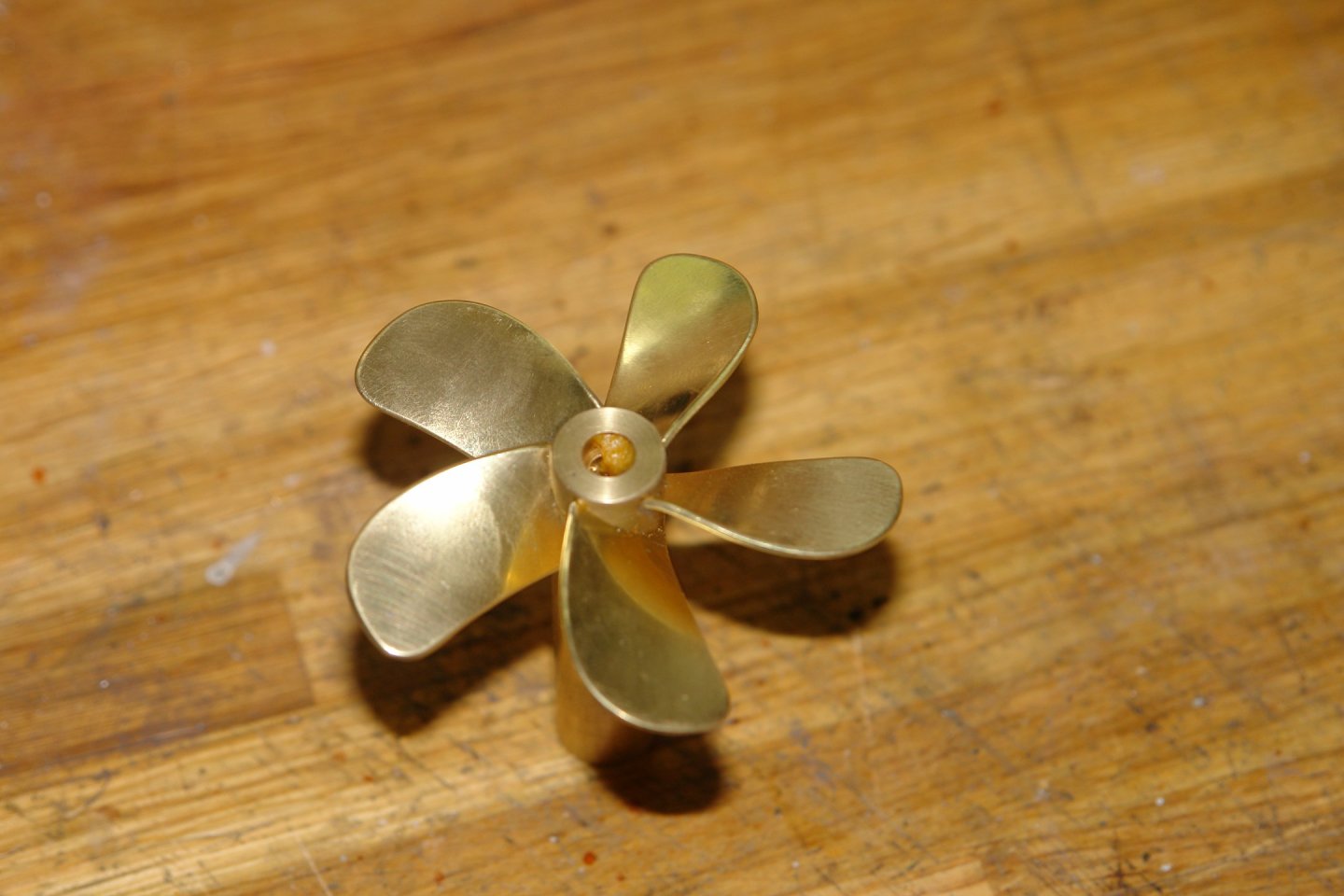
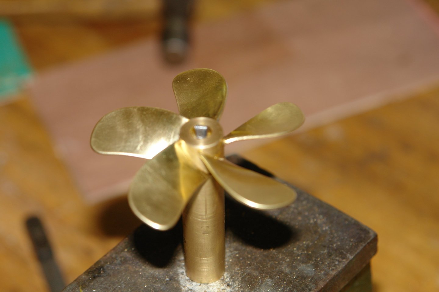
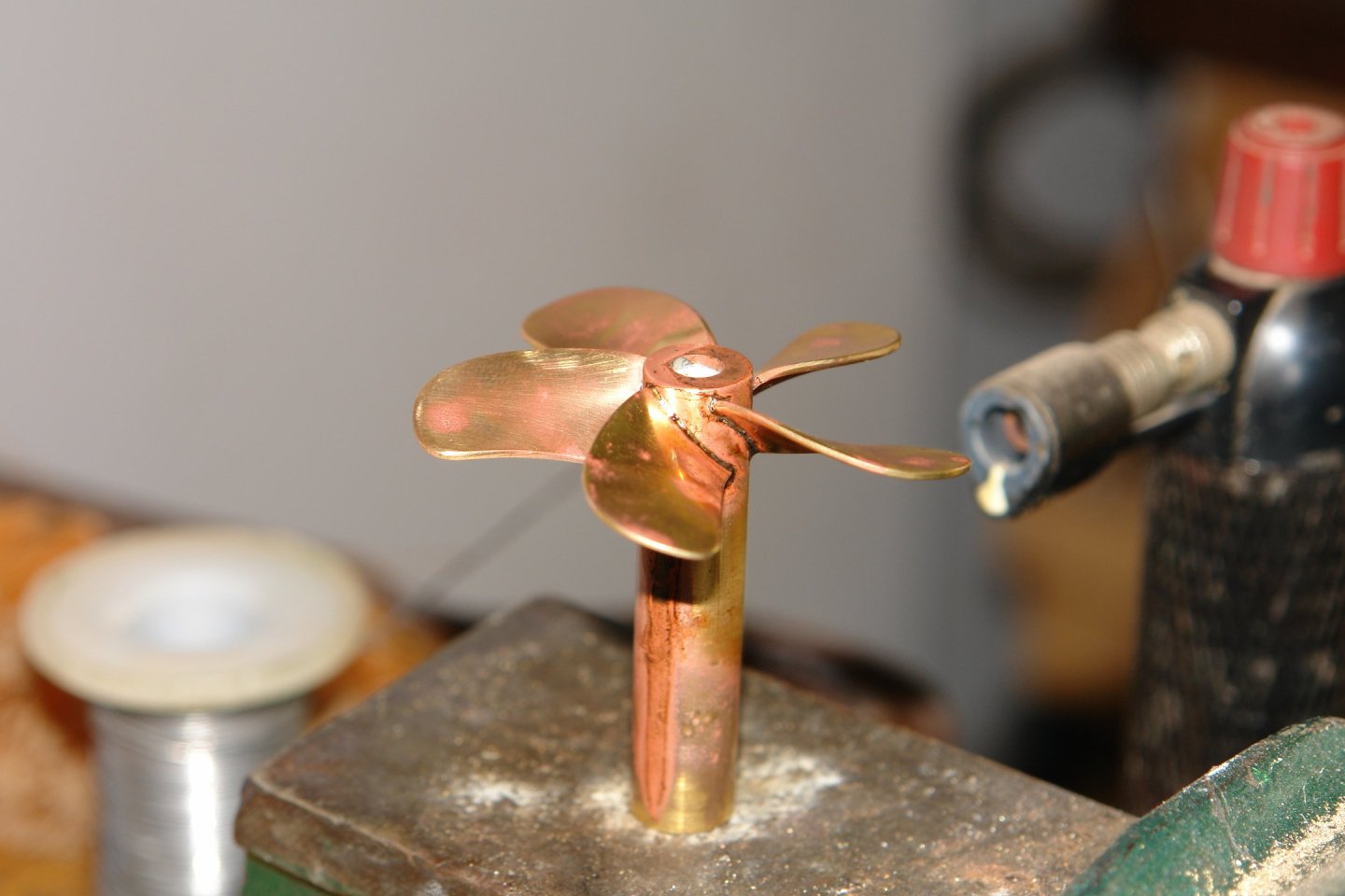
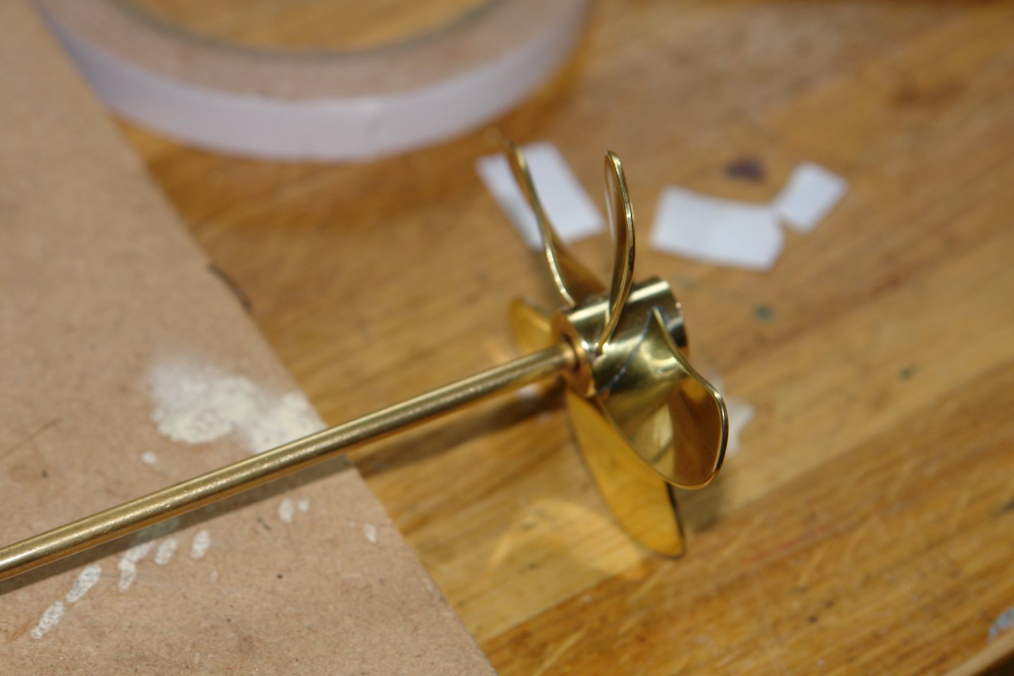
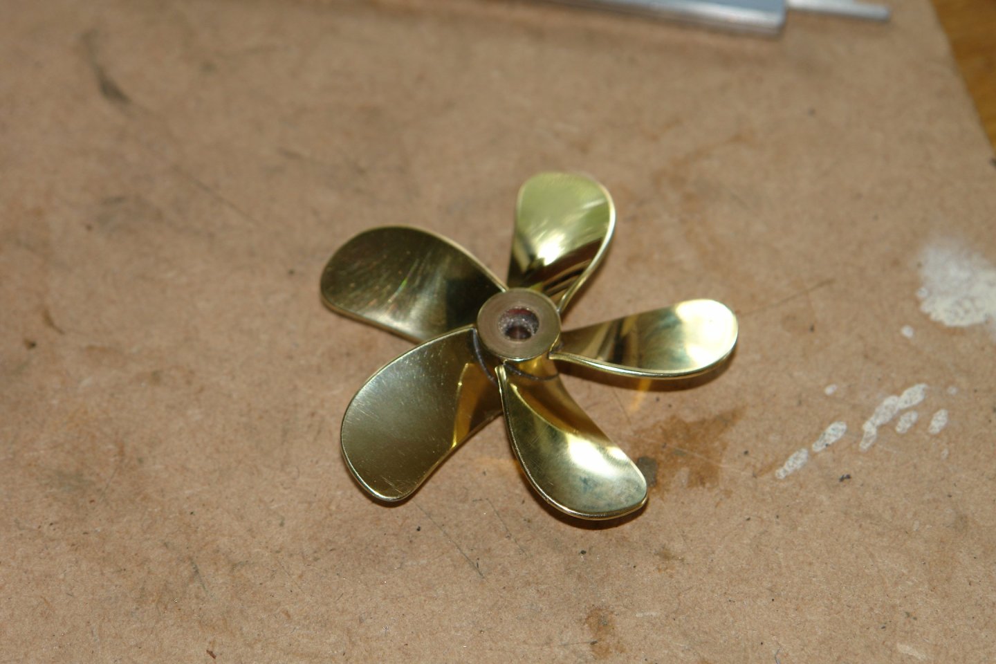
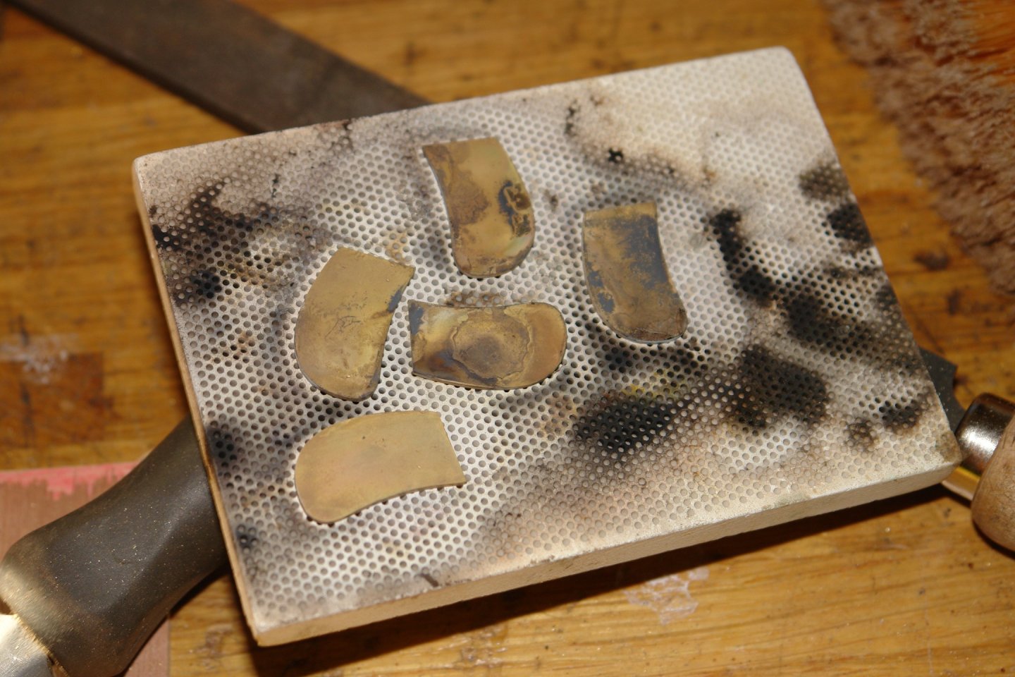
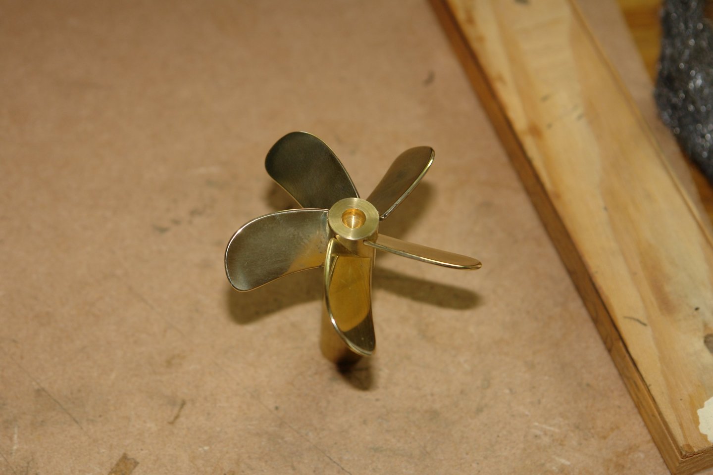
Thank you all for your prop comments but today's effort leaves me a little more satisfied with how it looks. I started this morning by designing a rather elaborate soft jaw bending tool. Ok, so not that elaborate🙂, but it did the job. the plywood soft jaws were held in place by double sided tape. My twisting jig also borrowed something from the Heath Robinson school of engineering. The vice is clamped to the workbench. The blue arrow is pointing at a plywood shim which controls how much of the blade is clamped by the vice. The red arrow is pointing at a line on the vice jaws that allows me to position each blade at the same spot in the vice. The green arrow is pointing at a line drawn on the bench. When viewed from above the edge of the wrench indicated by the black arrow aligns with the line on the bench at the completion of each blade twist. Close up:- I manually controlled the twist with the wrench at three positions - 1/4, 1/2 and 3/4 of the blade length, judging the degree of twist such that the final 3/4 position twist brought the wrench into alignment with the line on the bench. I nested the 5 blades once twisted to check they were all essentially the same. They nested well but unfortunately wouldn't stay in place for the photo opportunity. I then sorted out the hub attachment. .040" holes were drilled in hub to connect the root slots with the hub bore. The blades needed to be a good interference fit in the slots so I raised a burr at the bottom of each blade with a centre punch (red arrow). This done the blades were pressed securely into the slots. Once assembled I set about soldering the blades in place. A small piece of solder was placed inside the bore of the hub. The next photo isn't the best but I think it shows the soldering set up. With the set up complete I then heated the bore until the solder melted and ran into the blade roots. The resulting assembly was then cleaned and polished. The soldering proved to be particularly clean requiring no excess solder removal. The excess hub was then cut off with a hacksaw. A brass rod was then glued into the bore and this was used to hold the prop in the lathe for the facing off operation. I was relatively satisfied with the result.


-
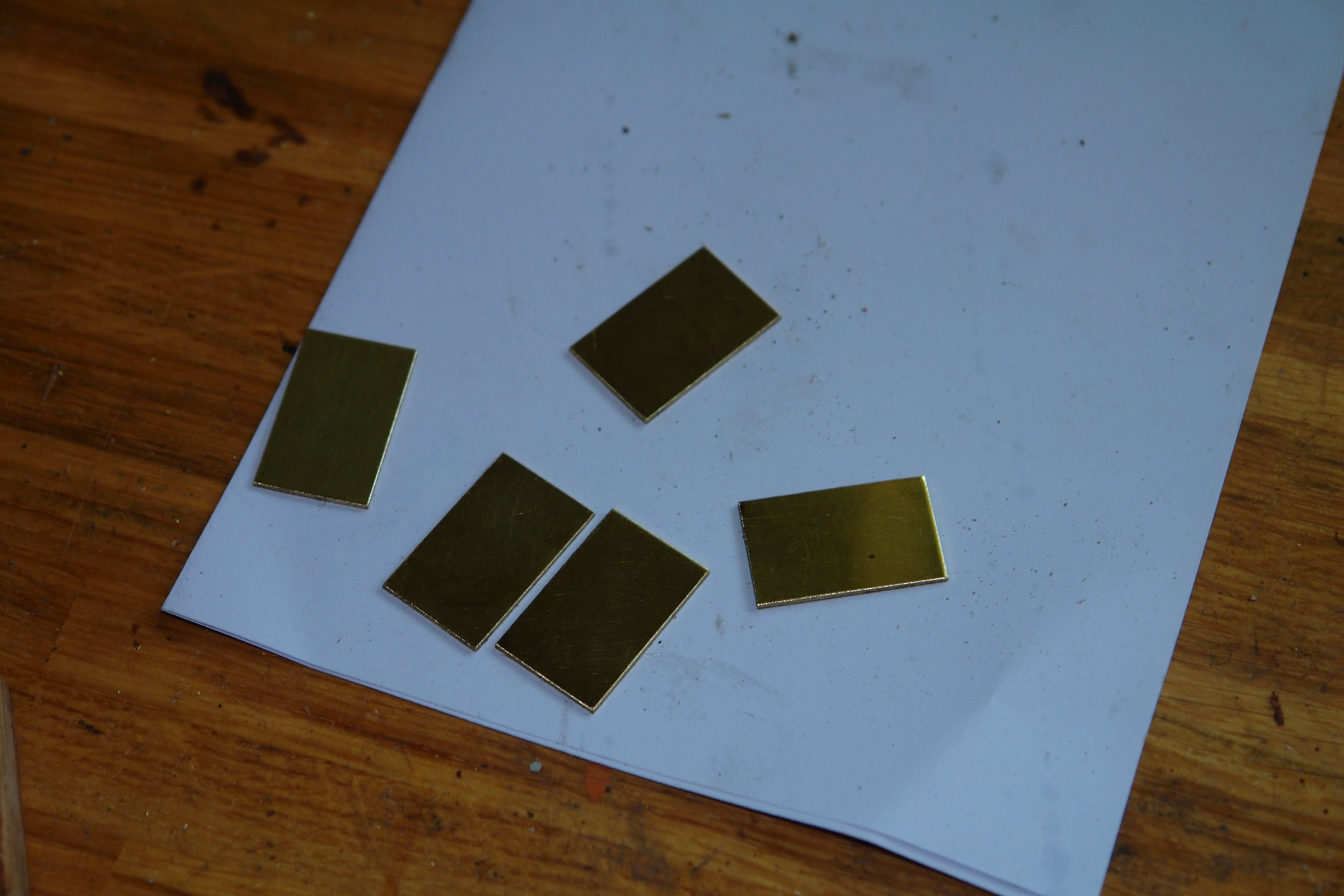
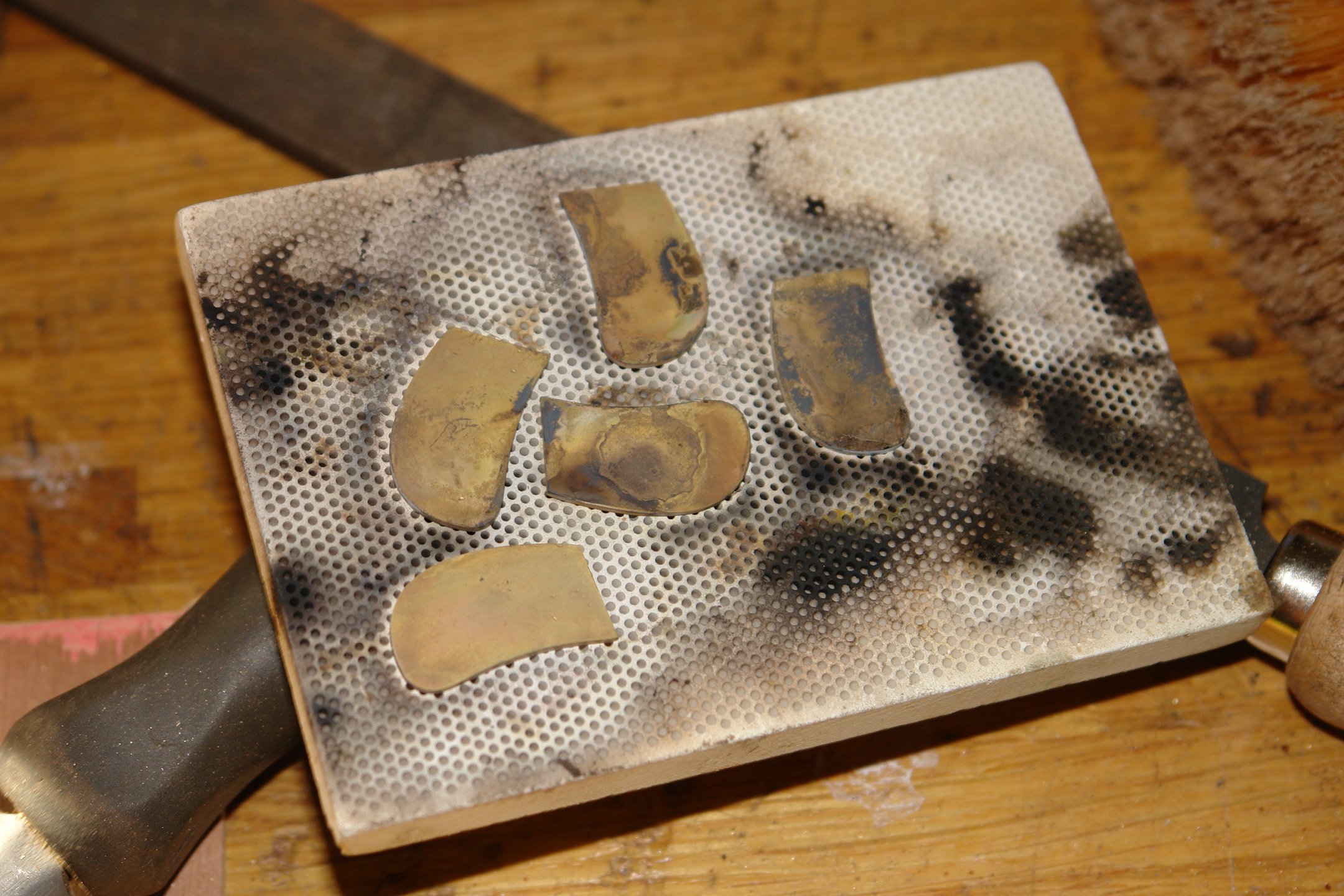
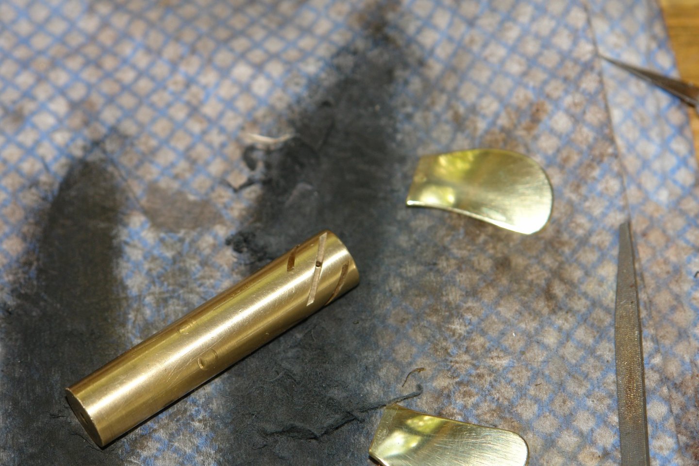
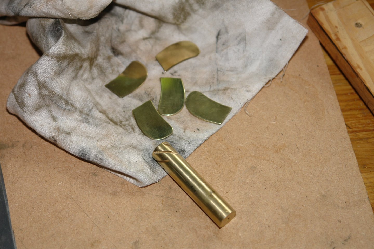
Thank you Rick, Mark, John and Richard. The last week flashed by but by the weekend we were back home and the workshop was reopened. The target is to get the prop finished this week before a week of river boating on the Thames (booze cruise). The progress update thus far:- You will recall that I was considering making the blades with location lugs. However having cut the hub slots I decided that the hub would provide adequate location without the lugs. 5 blade blanks were cut from .045" thick brass sheet. The blades .005" too thick so the thickness will be reduced to form a tight fit in the slots. The 5 blades were held together with double sided tape for the edge shaping operation. The shaping was done by a combination of milling and filing. I don't think that profiling the blade will add much to the looks of the finished prop so I am making a version without profiling. If I am unhappy with the result I will revert to profiling. The blades do need to be annealed to ease the twisting operation. The blades were heated to cherry before bing allowed to cool naturally. I did a bit of rough clean up before checking the fit in the hub slots. Without the twist the prop looks pretty poor. A bit of further polishing eased the fit and improved the blades visually. The blades were then disassembled and now await twisting. I have worked out a plan for doing the twisting and will have a go tomorrow.


-
Yep, disdain for authority kicks in early these day Andy. Thank you Keith. All his family agree with you.
-
By popular request here is an update. The good ship Ben was launched one year ago on the 1st September. His fitting out phase is proceeding to plan and he is due to transition to sea trials once his sea legs have stabilised. His armament has been somewhat delayed but we hope the Ben will be getting his teeth in the next couple of weeks. The hull is still a little porous but the caulk wadding is effective at preventing imminent disaster. By en large the Ben is a very happy little ship.

-
I find a laser level works quite well for that.
-
It's quite a complicated thing isn't it. I assume it had many uses including powering the forward derricks as well as anchors?
-
When my Byrnes saw failed I was able to make it run by manually rotating the blade. Once started it ran quite normally even with a dud capacitor.
-
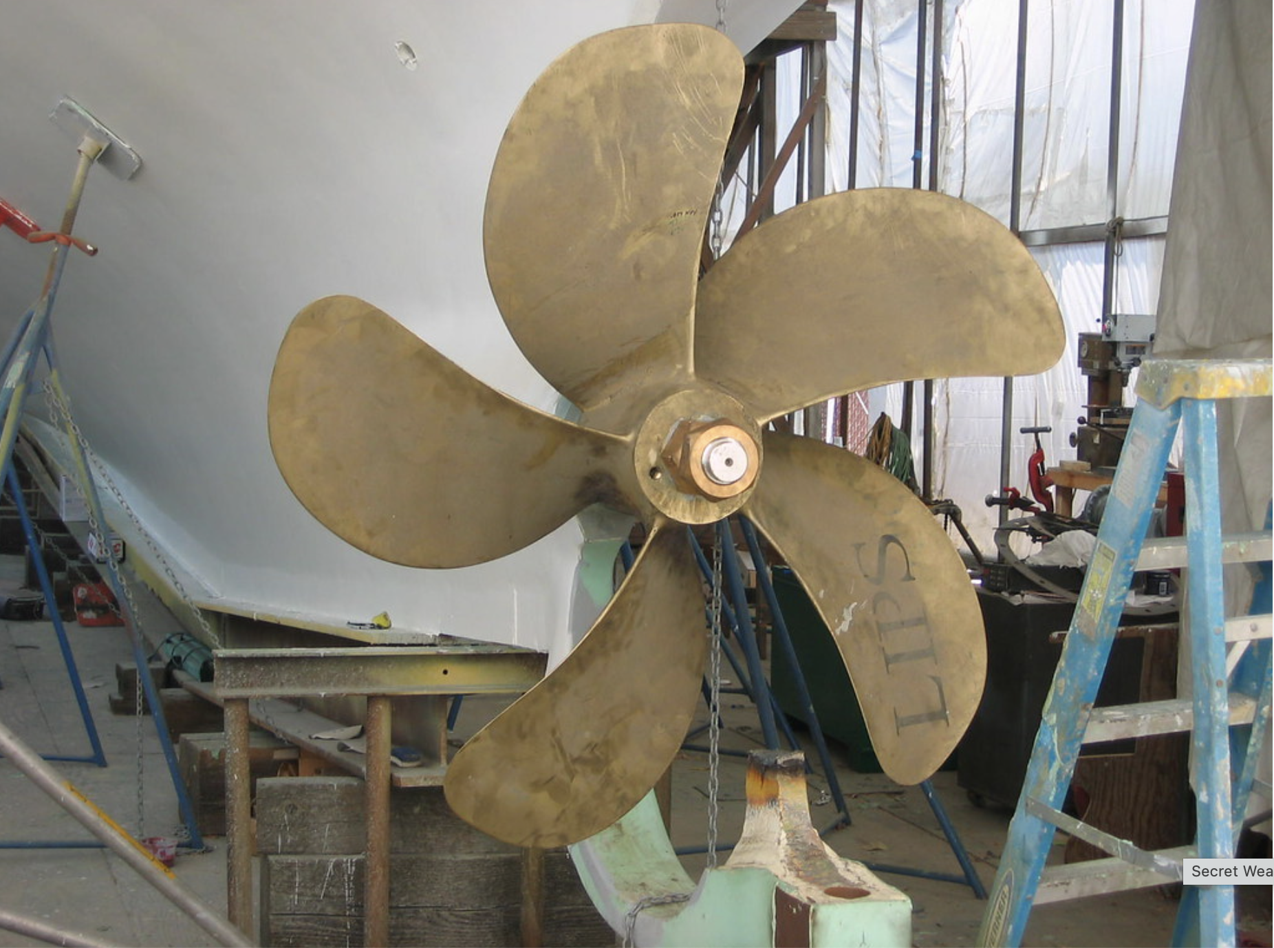
` Eberhard - correct I didn't have one. However I would probably have still gone for the single point tool. I find It hard to get slitting saws to run truly flat and they seem to inevitably produce a slot that is slightly wider at the mouth than at the throat. I find I don't have the same problem with single point tools. Thank you Andy - It is already in the fridge. Thanks Phil. Yes that is a nice traditional propellor - probably very similar to the one originally fitted to Cangarda. The current Cangarda prop is a much more modern shape and probably a little more efficient. I don't think I need to worry too much about the bade profile as it won't affect the look very much and I don't have to worry about efficiency on a static model. Gary, my sailing experience is that a flailing sheet always finds something to lasso, rip off and dump in the sea, irrespective of the shape.🙂 Druxey - thank you. Grandpa (and Grandma) is the other half of the grand parenting team. We were allocated Grandi and Nani by the granddaughter and it stuck. I think she thinks we are less serious. 😬 Keith - will do.
-
Oh good - no need to discover more surperaltive piping words. that's a heck of a lot of fairleads.
-
Thank you Keith, I’ll pass on your good wishes on Sunday and maybe even post his birthday photo.
-
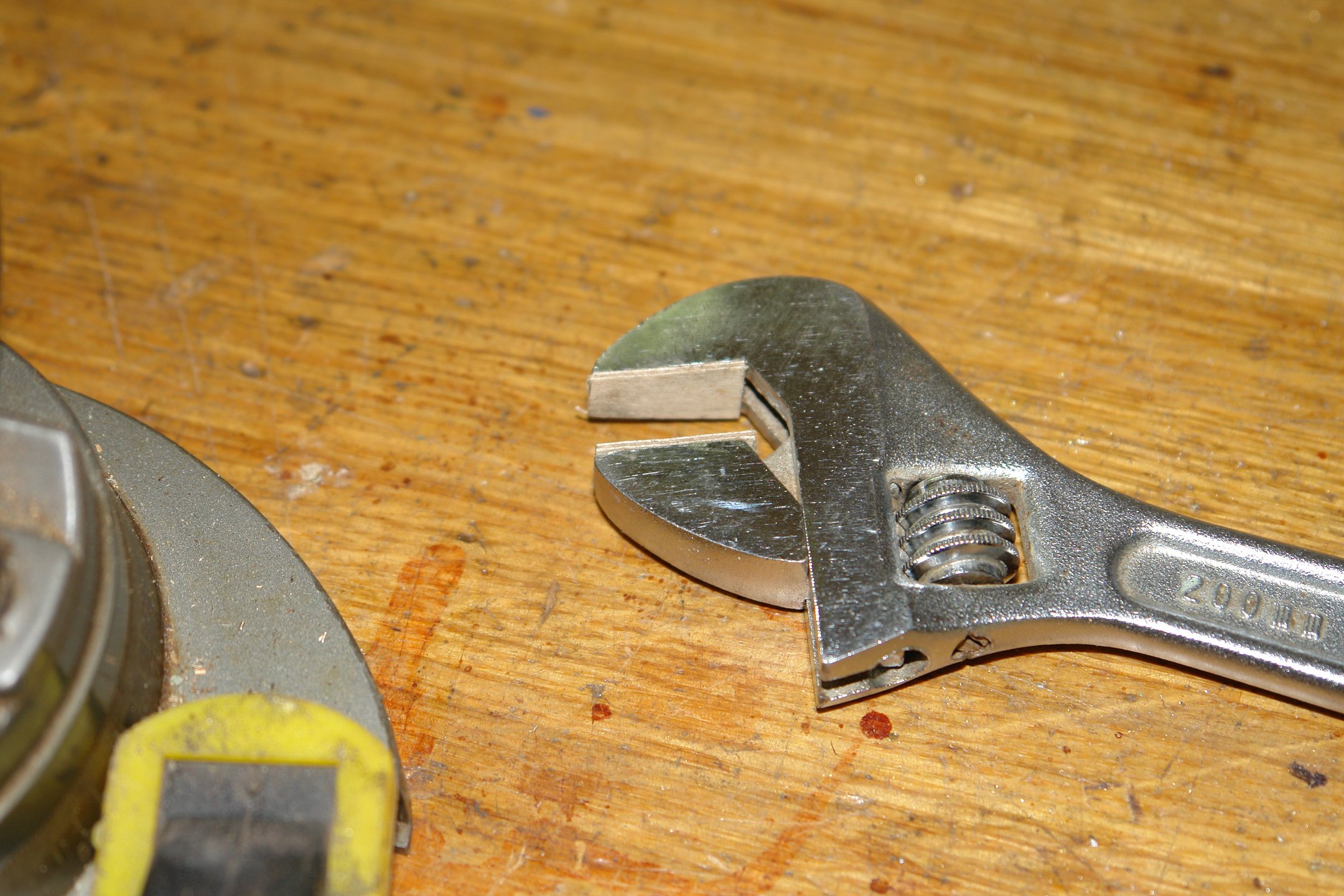
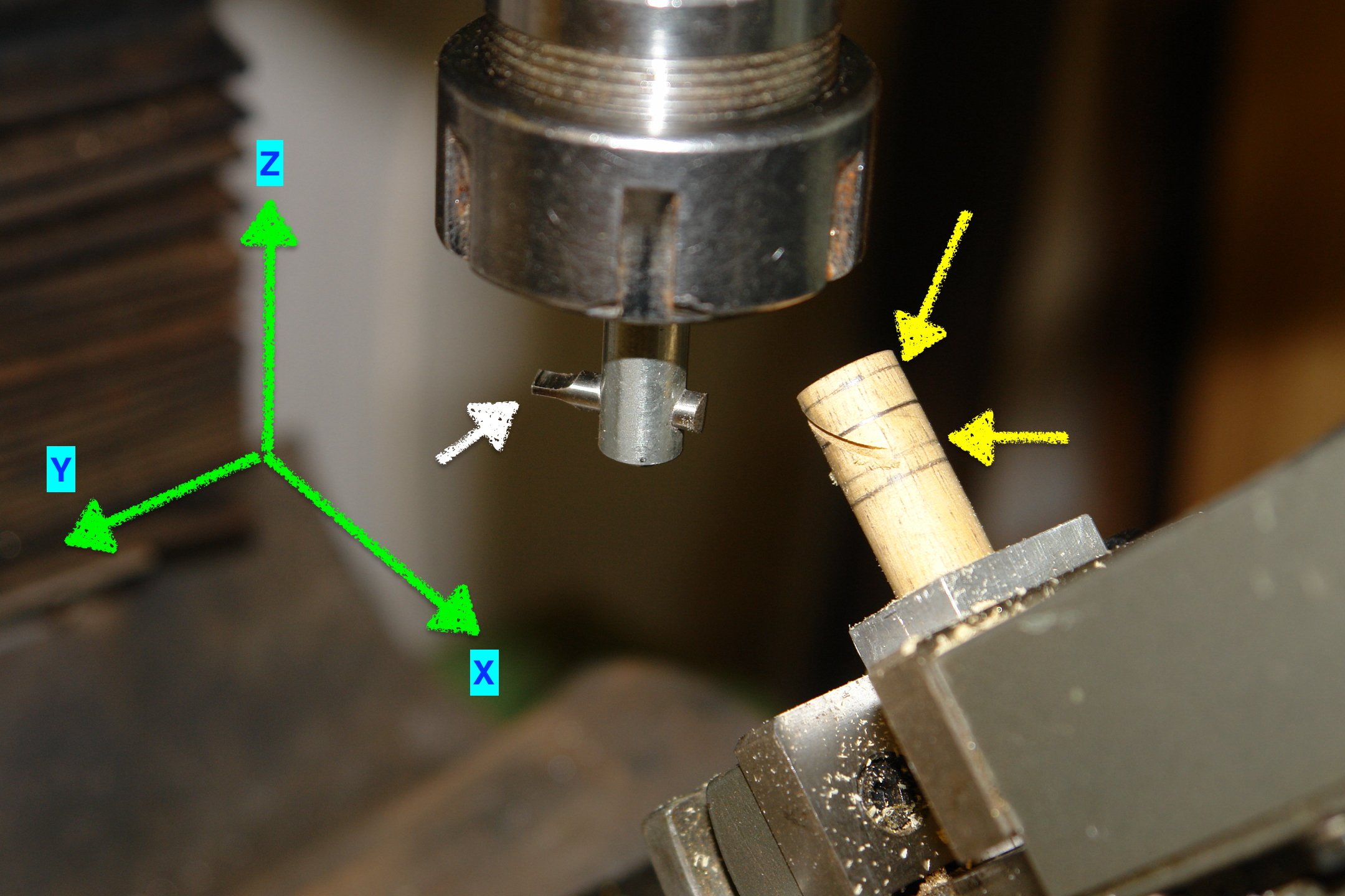
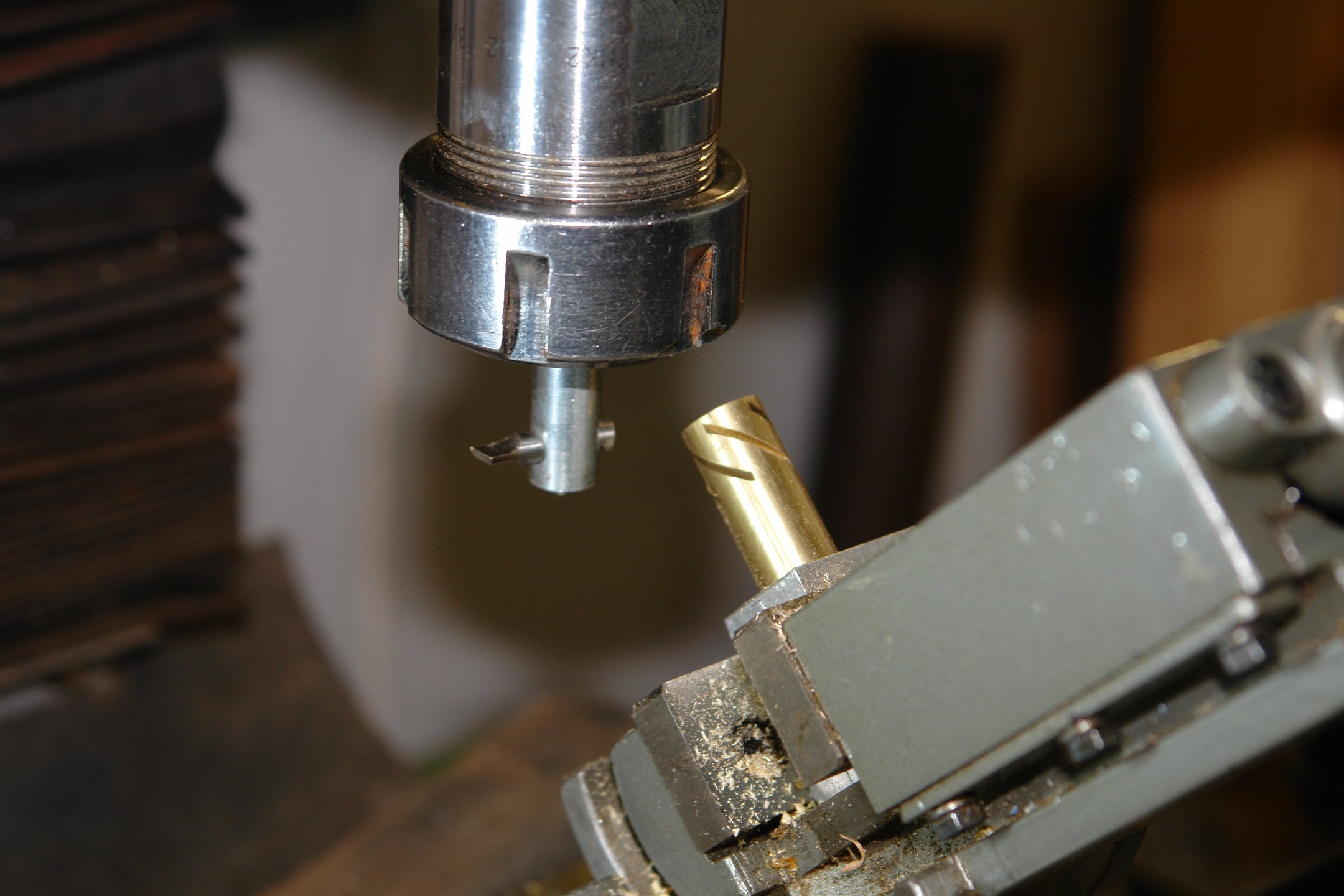
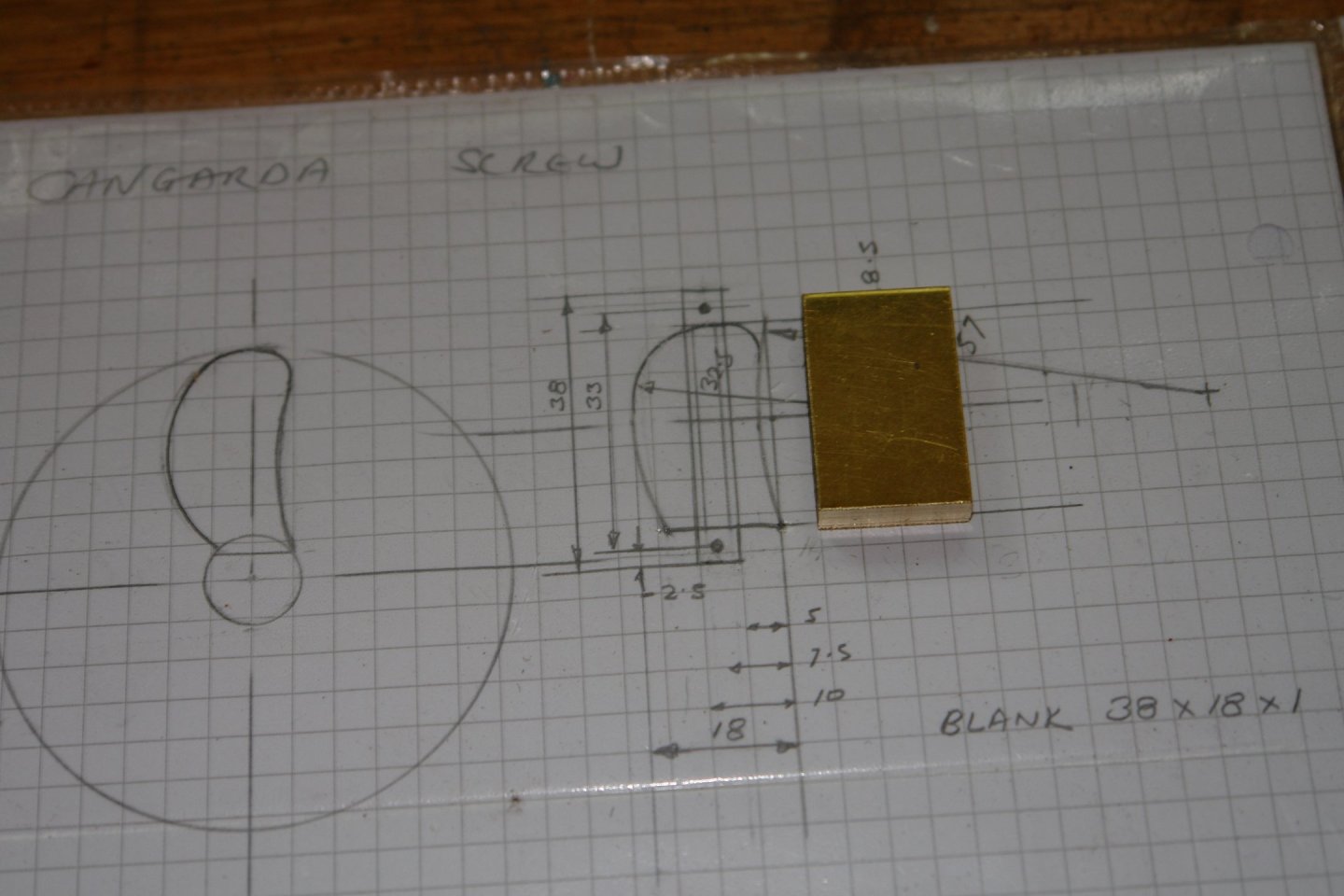
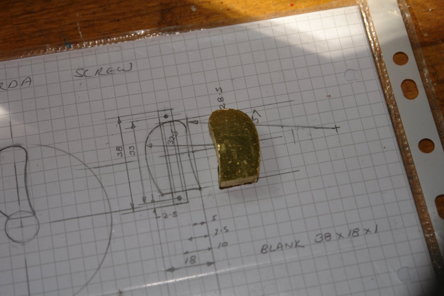
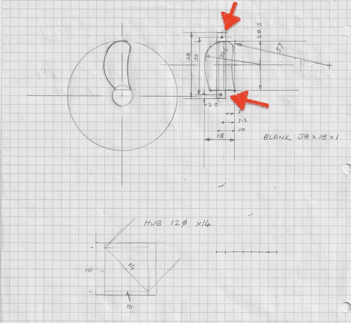
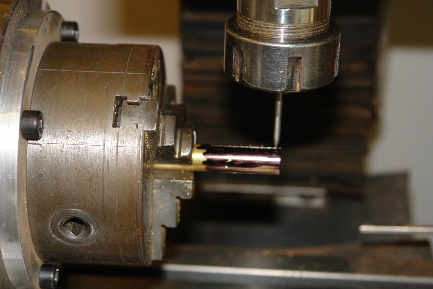
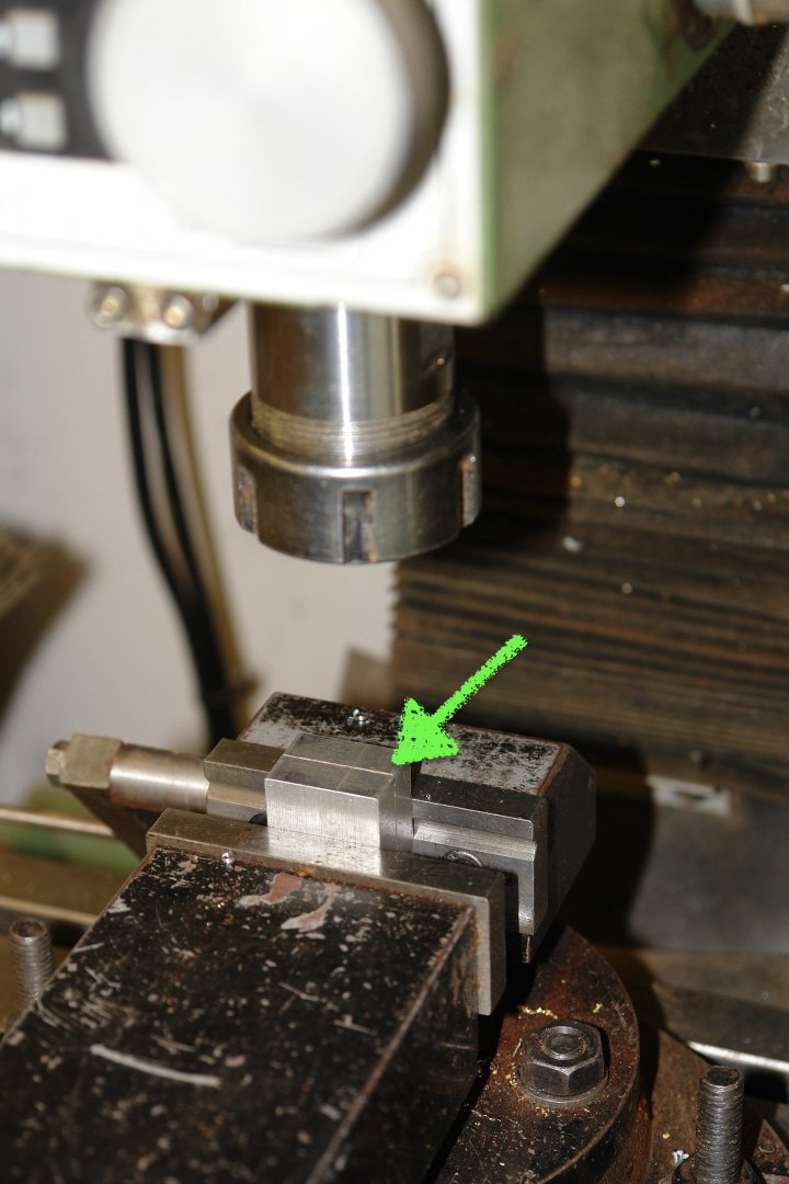
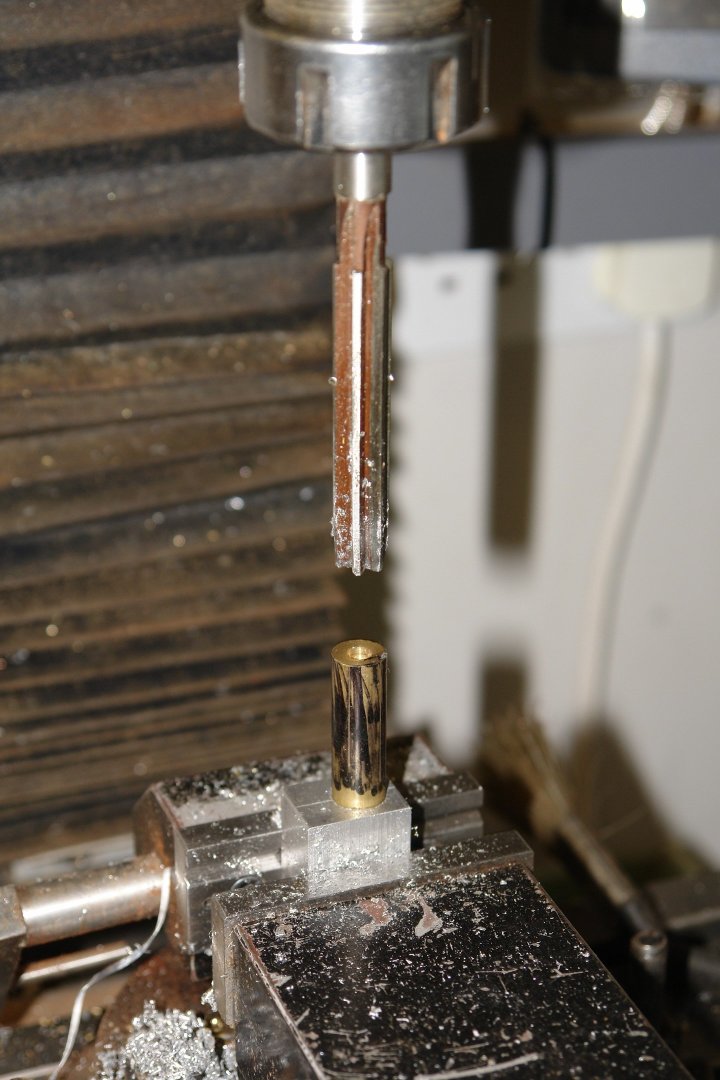
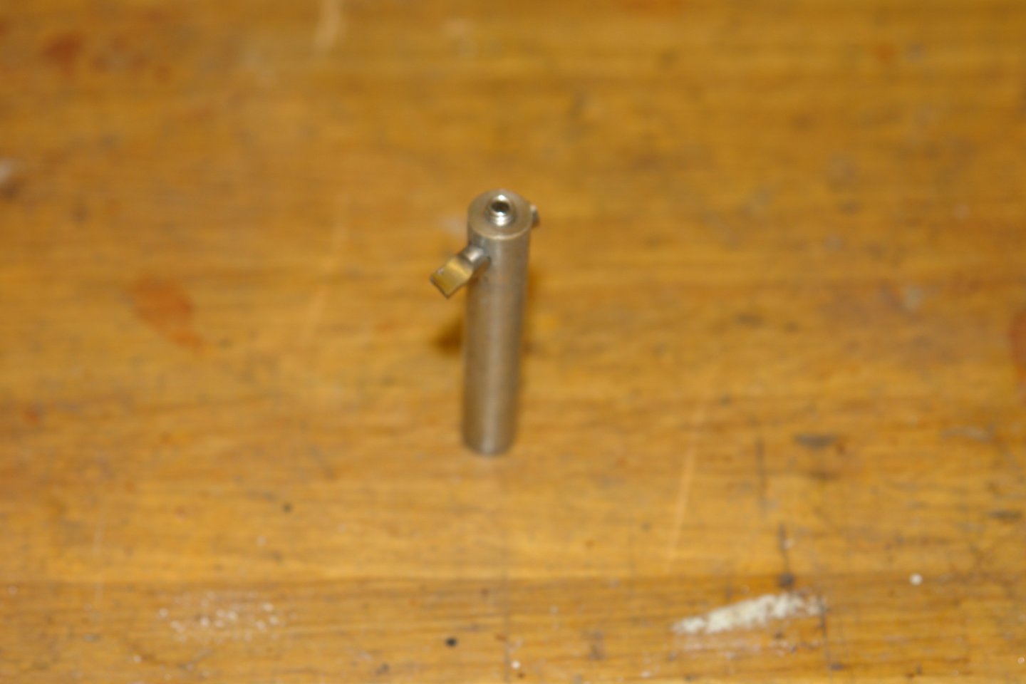
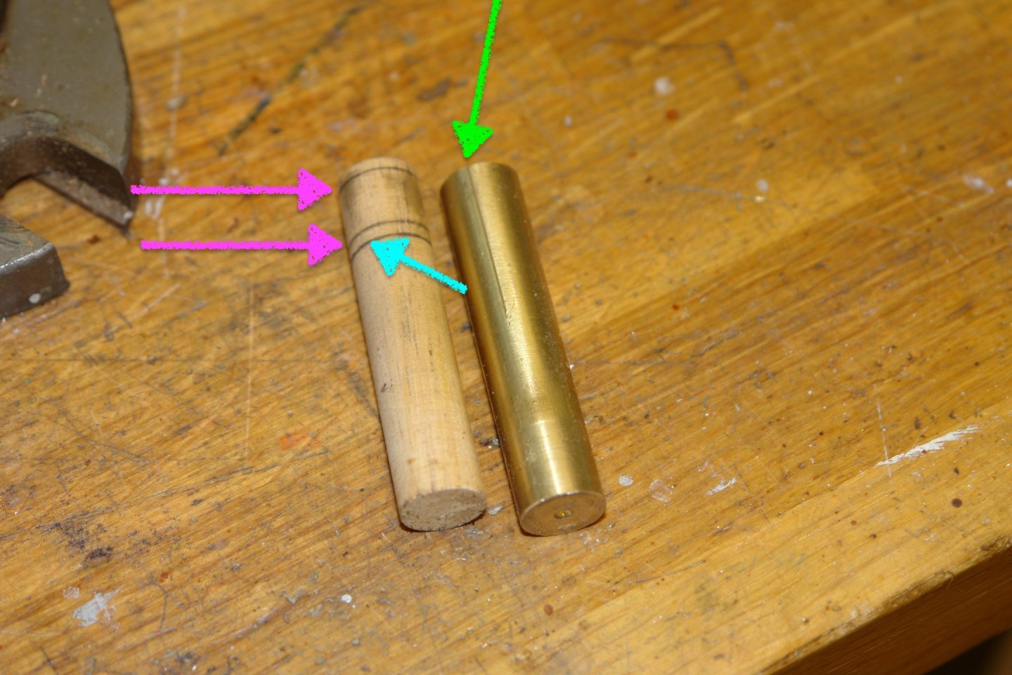
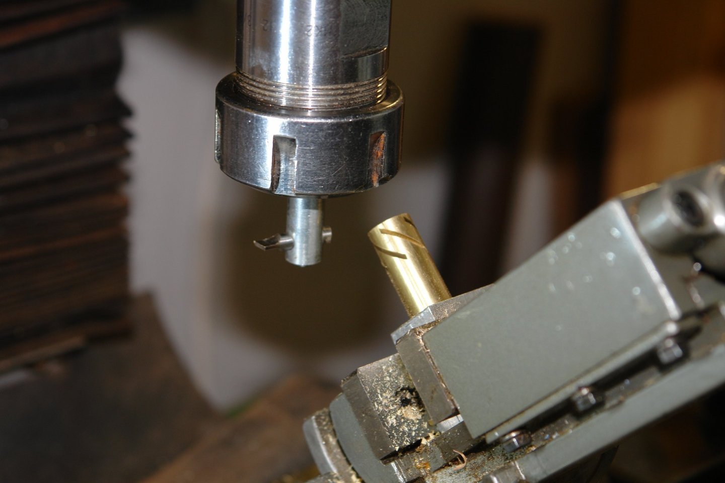
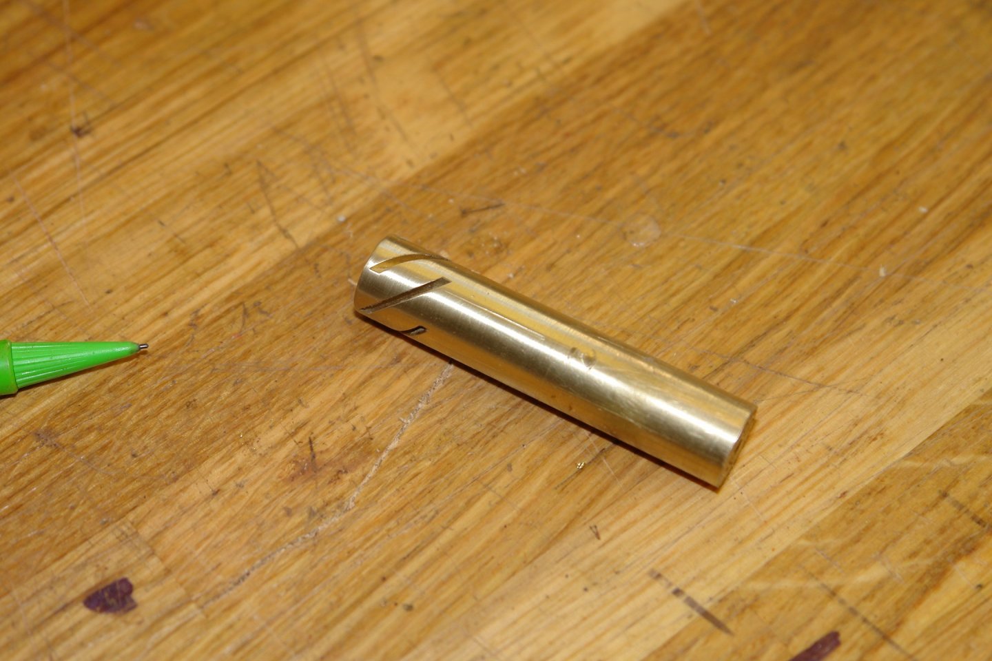
I have started work on the prop and rather than wait until it is finished I thought I would post a step by step description of the work. I won't be working on it daily due to family commitments (grandsons 1st and granddaughters 5th birthday coming up). It seems unbelievable that Ben first appeared on page 4 of this log almost exactly a year ago. Anyway moving on here is the start. You will probably recall the sketch from the last post. I estimated the shape of the blade from the best available photo. The blade is wider than appears in this stern view and as such I had to further estimate its width and shape. The image with the two red arrows above is the best I could come up with for the blade shape. The red arrows are pointing at sacrificial tabs that I thought I might need for location during the fabrication process. At present I think I may be able to get away without these. We shall see. The first part of my fabrication plan is to part machine the brass hub. The hub will be .472" (12mm) diameter by .551"(14mm) long. The blade angle at the hub is 45 deg and of course the blade angular spacing is 72 deg (5 blades). I want to machine the hub to accept the blades and this involves cutting 5 slots at the 45 degree angle. After some head scratching this is how the slots were cut. Step 1 was to mount the correct diameter of brass bar horizontally in a rotary table centred below the spindle of the mill. A scriber was then mounted in the mill chuck and this was used in conjunction with the rotary table to scribe 5 axial lines along the exposed end of the bar. Step 2 then involved making a location feature for the subsequent machining operation. I cut and squared up a 1" x 1" by 3/4" piece of aluminium bar. This was set up with the narrow edge centred below the mill and a line was scribed on the bar (green arrow below). Step 3 was then to bore a .437" hole .375" from one end. In step 4 the location feature was reamed out to .472" to take the round brass bar stock. The scribed reference lines on the bar stock and on the location feature allow me to accurately index the hub round to the desired 5 positions. Step 5 was to drill and tap the location feature to take a clamping bolt (red arrow in next photo). This done the location feature was mounted in a tilting vice set at 45 deg. Step 6 was to create a tool to cut the slots. I had decided on a slot width of .040" and I ground a single point milling tool and machined a tool holder to facilitate the cutting of this width. Step 7 - Because I didn't want to practice setting up the slot cutting on the brass bar I then machined up a wooden dowel to the exact same dimensions of the brass bar. On to the wooden bar I marked 3 lines. The blue line is .551" from the end and represents the length of the finished hub. The two pink lines are .080" from the finished hub ends respectively and these indicate the start and end positions for the 45 deg angled slots. The green line is pointing at one of the 5 scribed reference lines on the brass bar. Step 8 - The tilting vice was bolted to the milling table and the Z axis was adjusted until the single point cutting tool (white arrow below) was centred between the two lines indicated by the yellow arrows. With this done the Y axis was adjusted until the slot length touched both the yellow arrows lines at the extremity of the cut. These adjustments being done while testing the results on the wooden dowel while cutting using only the X axis traverse. Once I was satisfied with the results the Z and Y axis was locked. Step 9 was then a simple case of mounting the brass rod and traversing the x axis to cut the slot before indexing round by 72 deg and then traversing the x axis to cut the next slot etc, etc, etc. The slot cutting took about 5 minutes. The rest of the procedure took the best part of half a day. I should have explained earlier the the protrusion of the bar was always the same because it was bearing on the bed of the vice during each cut. More to come.


-
I look forward to it Andy. The revelation that is - not your appointment with the padded cell - although to be fair this might also be quite informative for some of us. As a child I shared your Spitfire dilemma which was why I always favoured the Fairey Swordfish. Your great work on the framing continues to impress.
- 174 replies
-
- 4
-
-
- Vigilance
- Sailing Trawler
- (and 1 more)
-
Seconded. That would be very useful information.
-
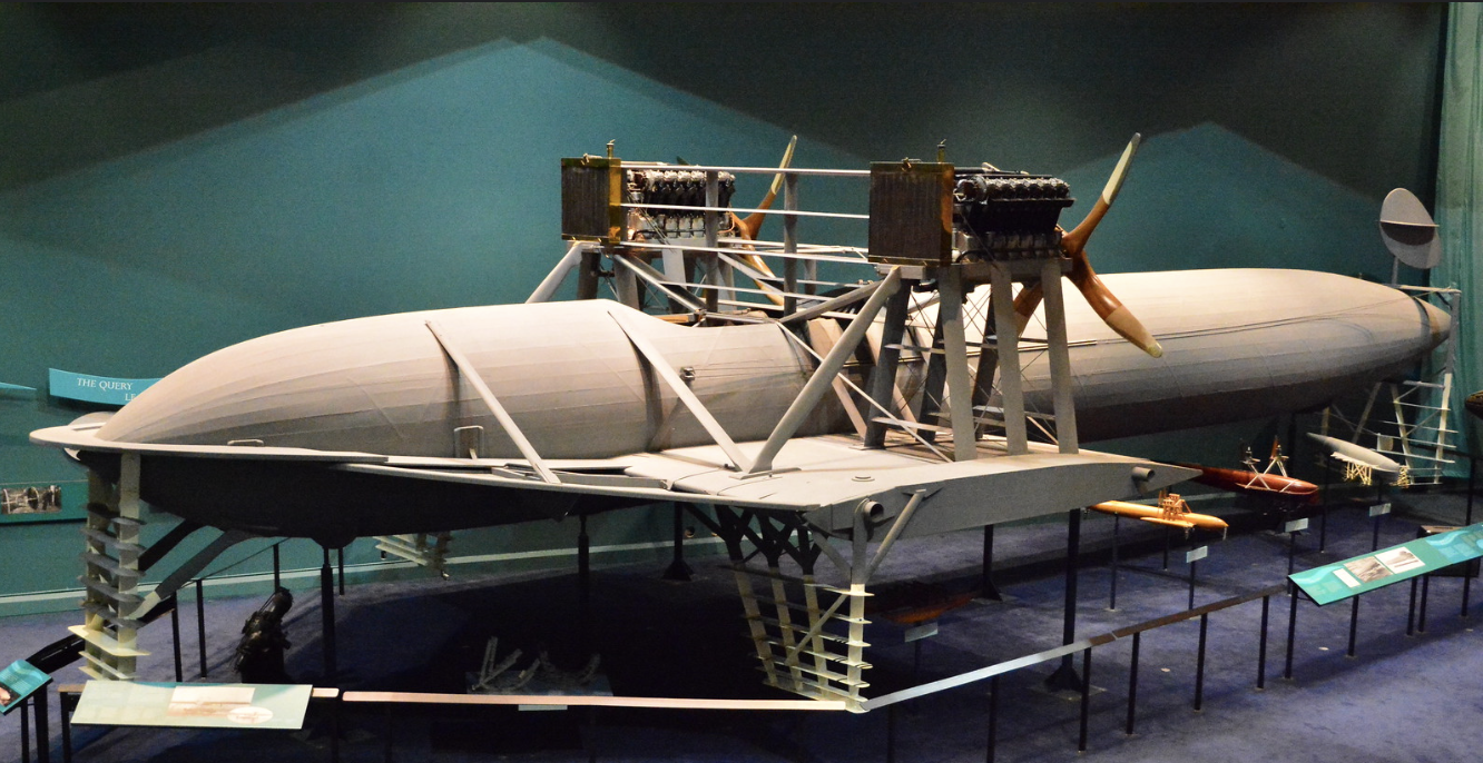
All looking very good Greg. I remember some years ago viewing an early hydrofoil developed by Alexander Graham Bell in Baddeck Nova Scotia. Its wasn't quite as elegant as your replica but would make an interesting model. I particularly liked the Venetian Blinds foils.
- 288 replies
-
- 8
-
-
- Santos Dumont No. 18
- hydroplane
- (and 1 more)
-
Keith - A good looking fully rigged raft. A new category of MSW vessel.
-
Roel / Keith - thank you both for your insights and support. Thanks to everyone for the likes.