KeithAug
-
Posts
3,980 -
Joined
-
Last visited
Content Type
Profiles
Forums
Gallery
Events
Everything posted by KeithAug
-
 Rick - thank you for the extra photos. I have a magnificent selection due to your efforts so the new owners restriction won't matter a lot. I think he / she will find that the horse has bolted if they ever find this build log!😀
 -
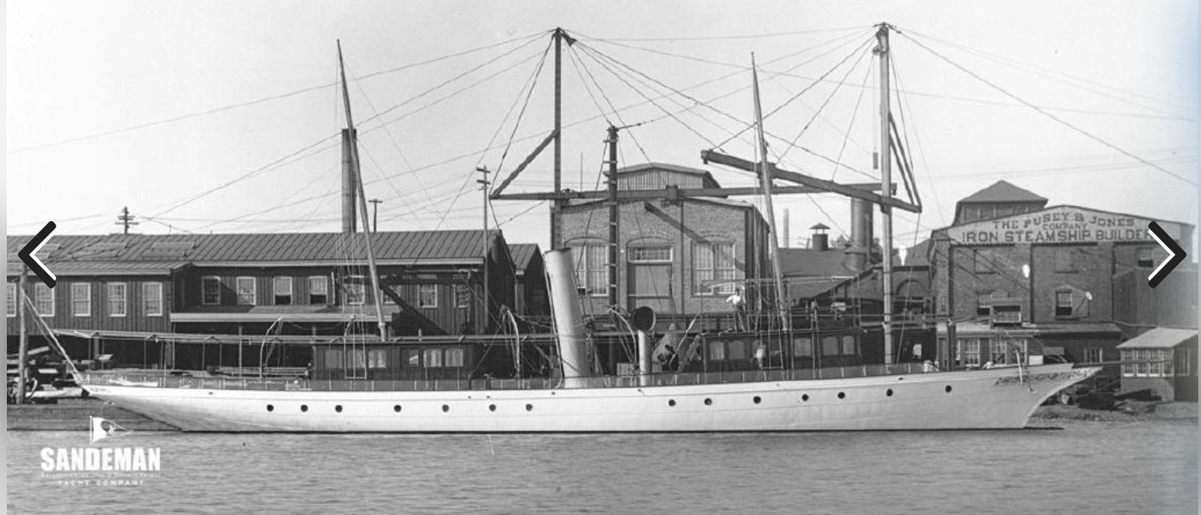
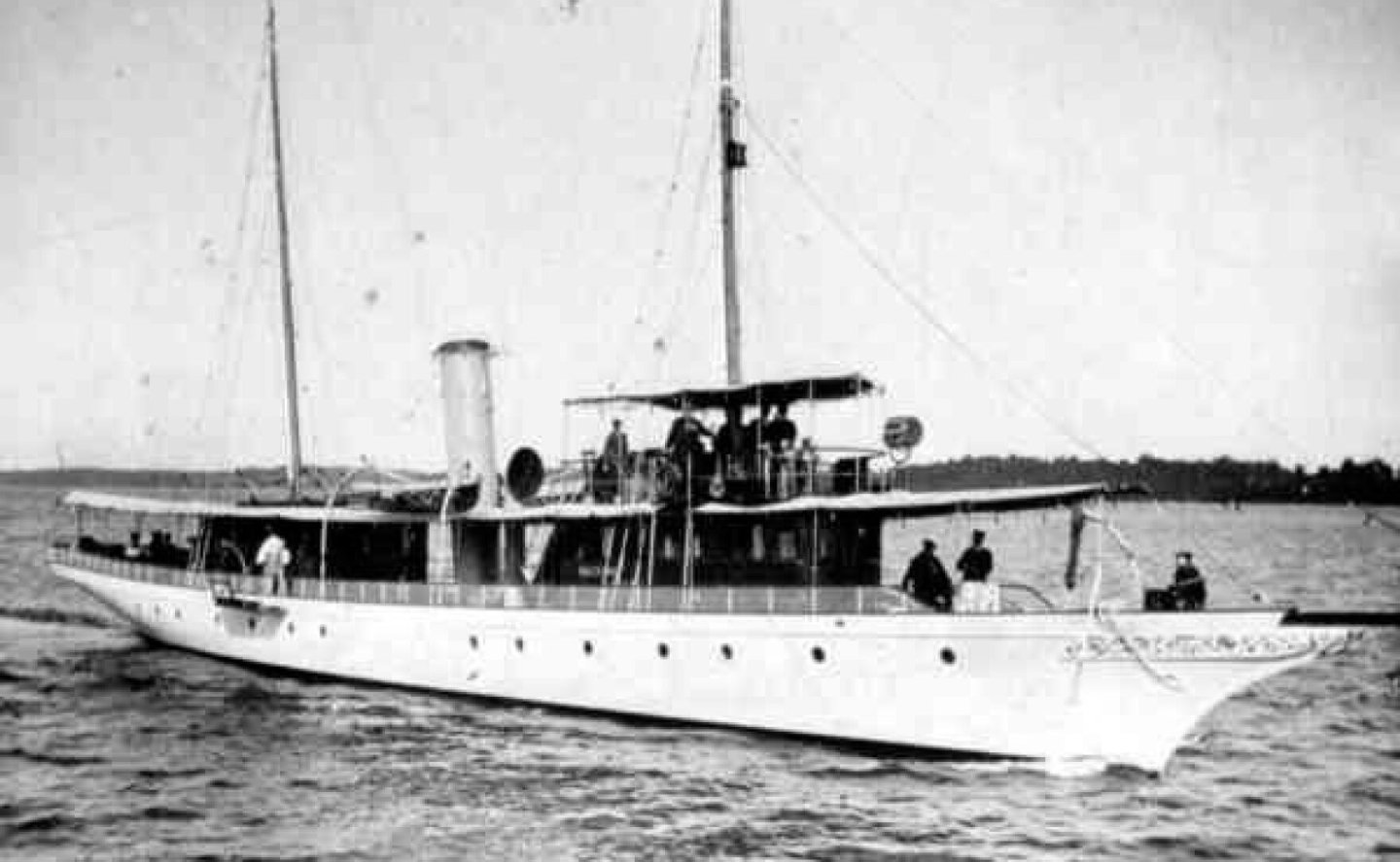
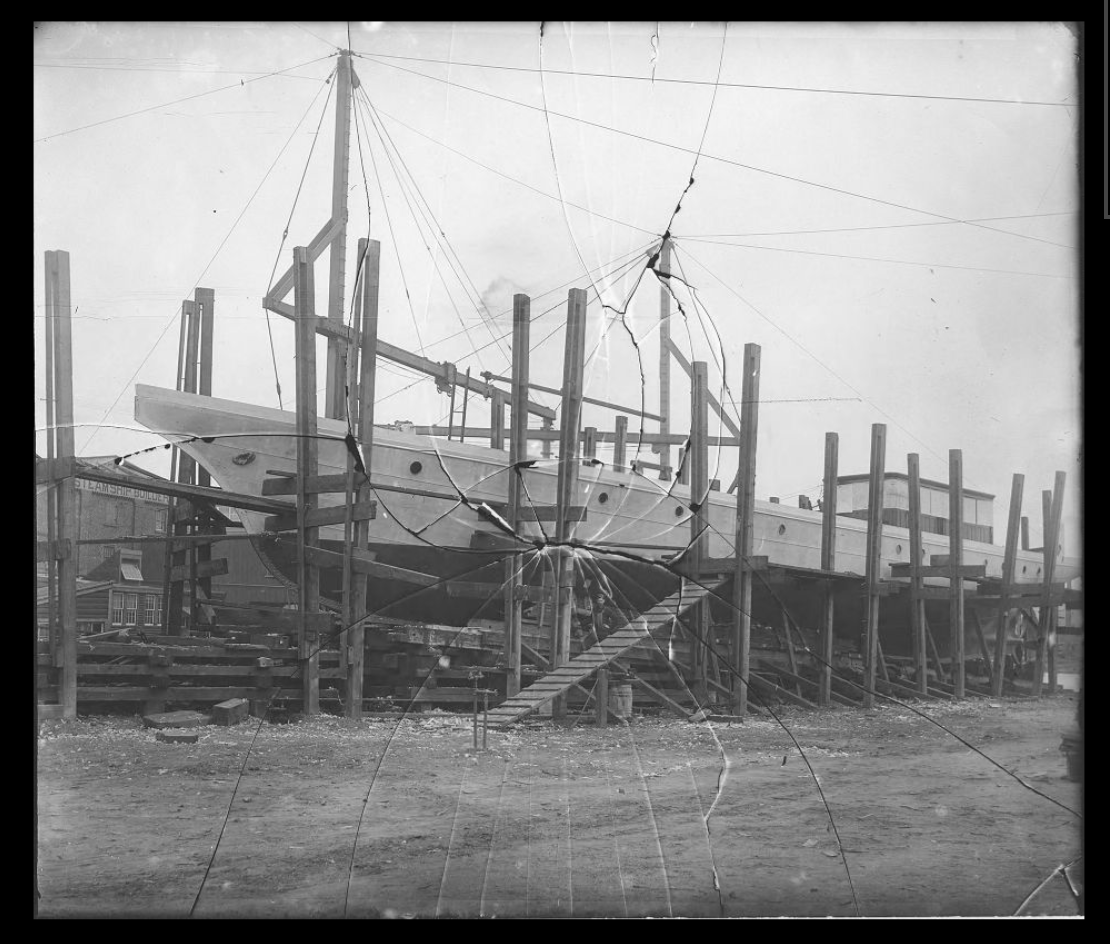
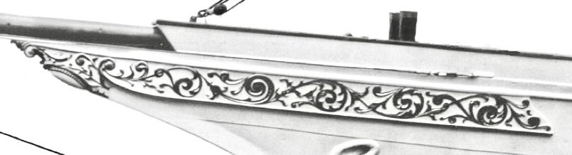
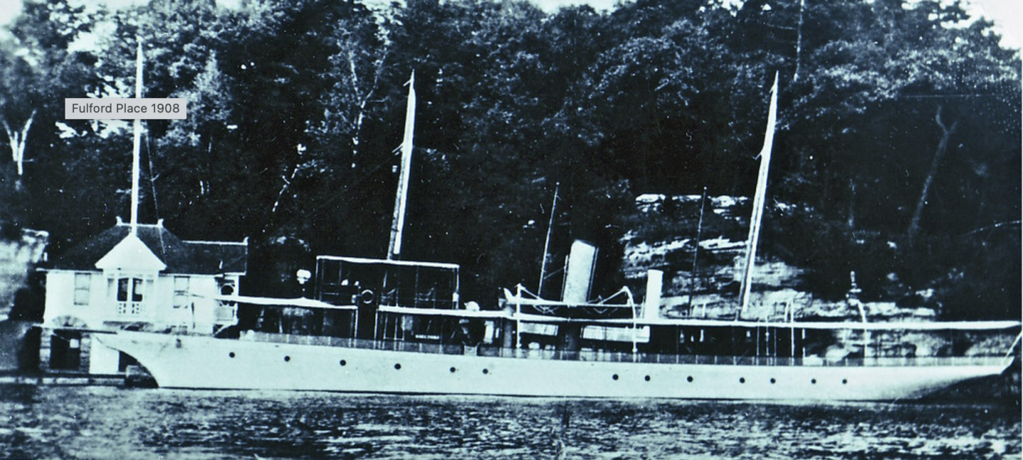
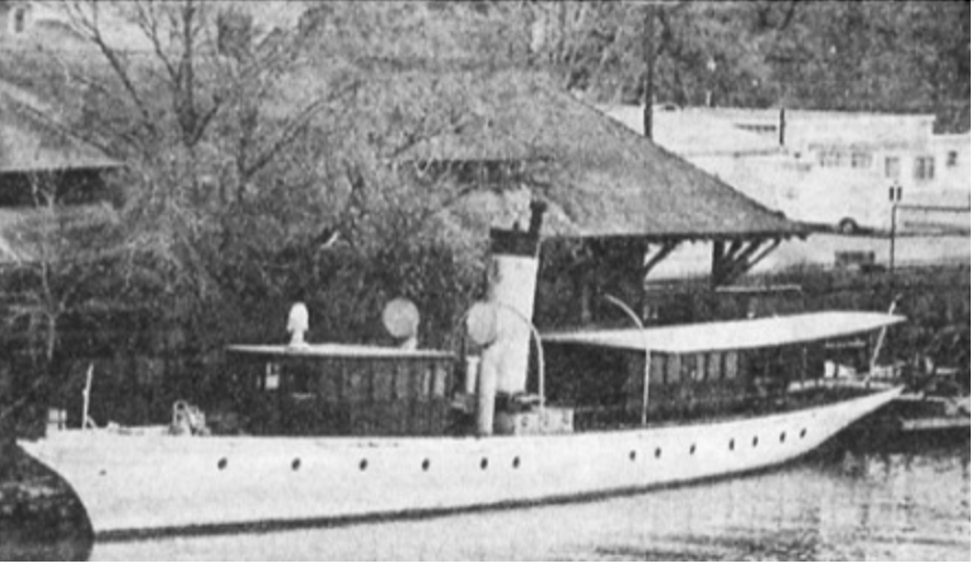
Richard - I thought you might be referring to the original, unfortunately I have found very few photos of the original. Here is all of them. None contain any useful detail on the vents.

-
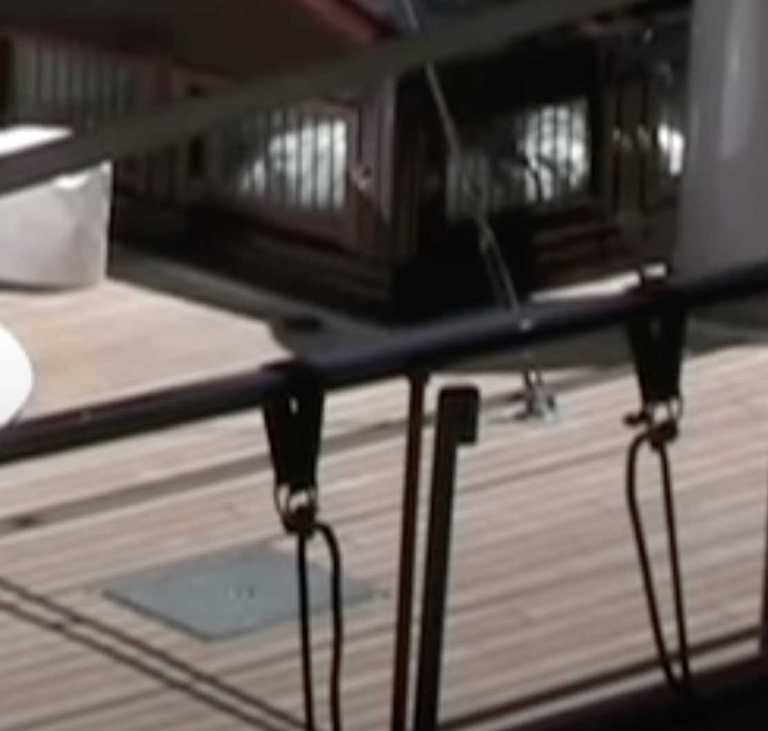
Keith, Andy, Richard. She was built with them. Here is a screenshot from a video dated 2010, only a matter of moths after launch. Keith - I quite like the awning framework. I think its going to look real nice in polished brass.
-
I guess you are correct Richard, however I can think of a number of simpler / more elegant / more aesthetic ways of achieving the same objective.
-
As a measure I like feet. I have two of them.
-
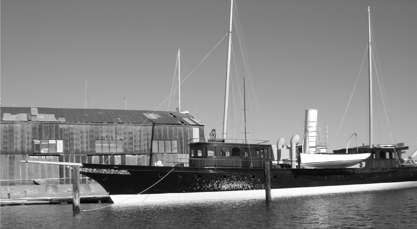
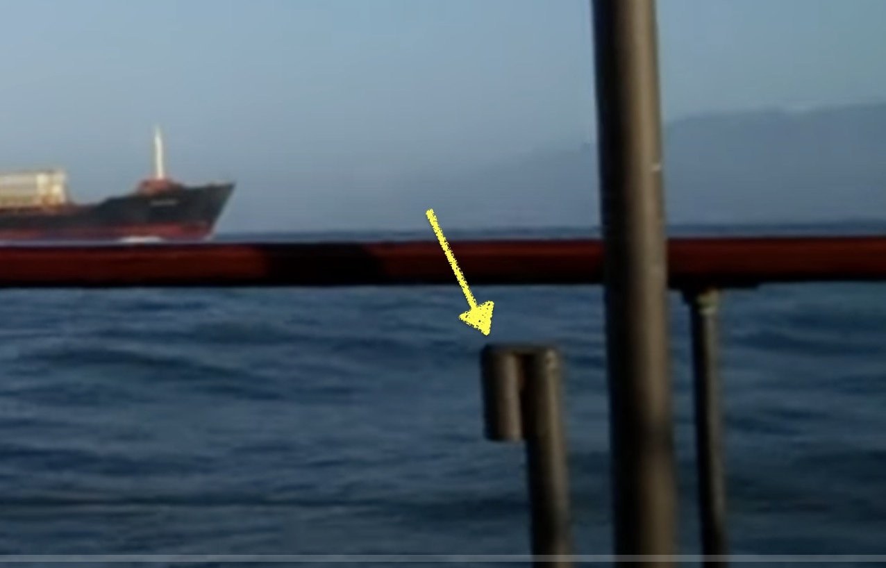
I had wondered about that John but in the final photo the 2 tubes don’t seem to be connected across to form an inverted “u”.
-
Yes very tricky Andy. I think I would have been tempted to start with a piece of dowel and then bore it out to form a pipe. Then cut the pipe into strips before shaping / reassembling the strips to give the desired shape. However your effort looks pretty good to me.
- 174 replies
-
- 1
-

-
- Vigilance
- Sailing Trawler
- (and 1 more)
-
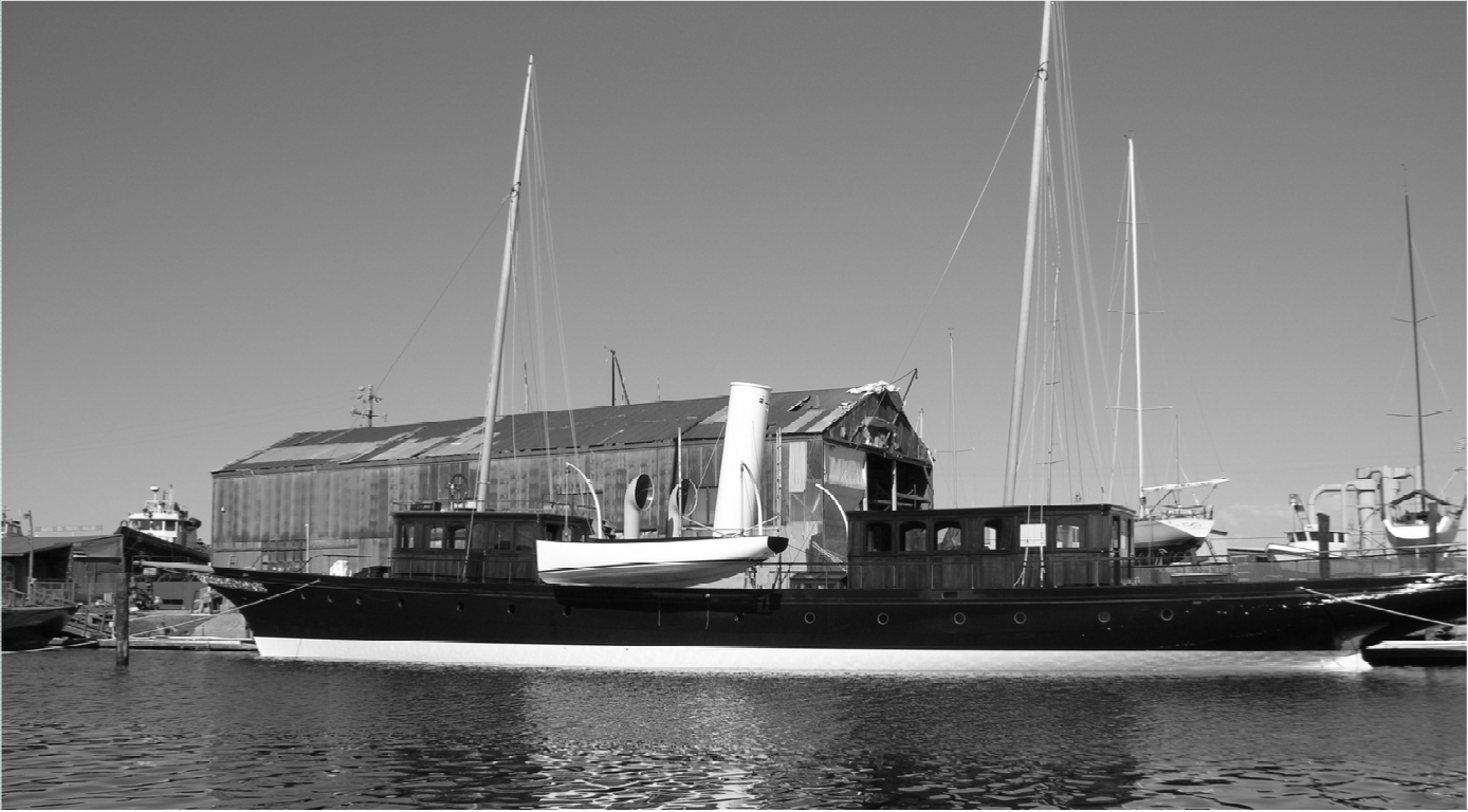
These things appear at multiple positions on the deck. In the last photo it looks like two pipes with a flat plate cap????????
-
I replace the capacitor recently - The original lasted about 8 years. I bought this on eBay and it worked fine. The simple test for a capacitor fault is to switch the motor on and kick the blade over manually (not with fingers). If it's the capacitor that is dud this should cause the motor to run. The function of the capacitor is to facilitate starting.
-
Brian - I thought this was a really interesting tool. In no way a replacement for a good miniature table saw but quite a useful device nevertheless.
-
Cap San Diego by mikegr - 1/160
KeithAug replied to mikegr's topic in - Build logs for subjects built 1901 - Present Day
Looking very smart. Welcome back. -
Rick, that is marvellous. For some reason I hadn't thought that it would be possible to get details of the masts. Information on the masts and rigging is a big black hole in my knowledge and based upon the photos I should be able to do a much better job on both masts. Many thanks. Thank you Richard.
-
I see the bow is “working out” quite nicely. Always good to find a use for a bit of weight lifting ironmongery.
-
Beautifully done Gary.👏
-
What about poundals and slugs, in the past measurement units had character, not like this modern SI unit stuff!
-
Keith - you need to consult a critic who is more like the right scale. Does Ole Bob have a view?
-
Ras - I always think that I should build the same boat twice to correct all the mistakes in the first one. I never do of course.
- 128 replies
-
- 4
-
-
- zulu
- sternwheeler
- (and 1 more)
-
All very confusing. It was much better when everything was measured in chains and furlongs.
-
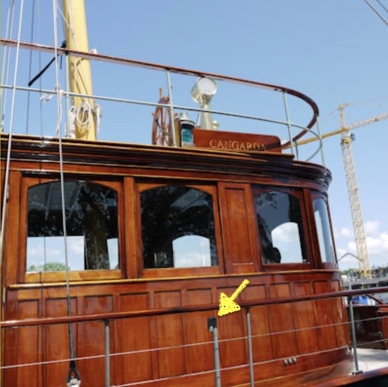
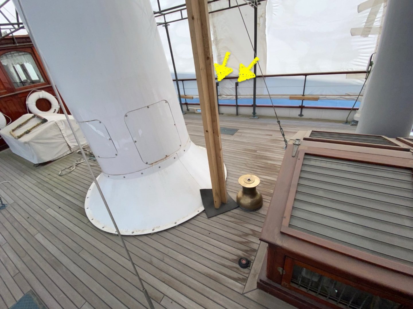
I'm not that clever Andy. So am I John. It tends to develop further each day on my dog walk. Thank you Rick. It is inevitable that I find the very bit of info I need the day after Cangarda departs. The only areas where I am a bit short of info is around the bowsprit - the various deck fittings and the protrusion through the bulwark. I think these were fairly inaccessible when you were aboard due to the covers being on. Also do you know if the roofs of the deckhouses are really white or is this just a protective covering? The details of the awning supports are very useful thank you.
-
Ras - It is funny what I miss in passing. I have only just realised Zulu has two paddle wheels. Are they on a common shaft or can they rotate independently?
- 128 replies
-
- 2
-
-
- zulu
- sternwheeler
- (and 1 more)
-
Love the dockyard crane Keith, what an amazing contraption.
-
Babies need lots of sleep Brian.🙂
-
Very crisp work Richard - the plan looks a little daunting.
-
I have a cunning plan.🙂 Thank you Rick, Pat, Steve, Keith and Tom. Also thanks to everyone for the likes and visits and advice. Tom, I have used it before - it is also a mini pillar drill. Made from a broken camera tripod.