Cathead
-
Posts
3,353 -
Joined
-
Last visited
Content Type
Profiles
Forums
Gallery
Events
Everything posted by Cathead
-
 Ian, great story, that's exactly why I'm taking this modular approach. I don't want to "ruin" this room and I don't want to have to throw everything out one day. This way a variety of outcomes are possible, from some or all of the scenes ending up in various local historical museums (of which we have several along this corridor), to possibly finding a new home with someone else. And if it does have to go to the landfill, it'll be a lot easier than ripping stuff off the walls and dismantling a messy web of permanent benchwork.
- 131 replies
-
- 10
-

-
And here I thought the drop saw was a mythical shop tool used by the legendary drop bear...
-
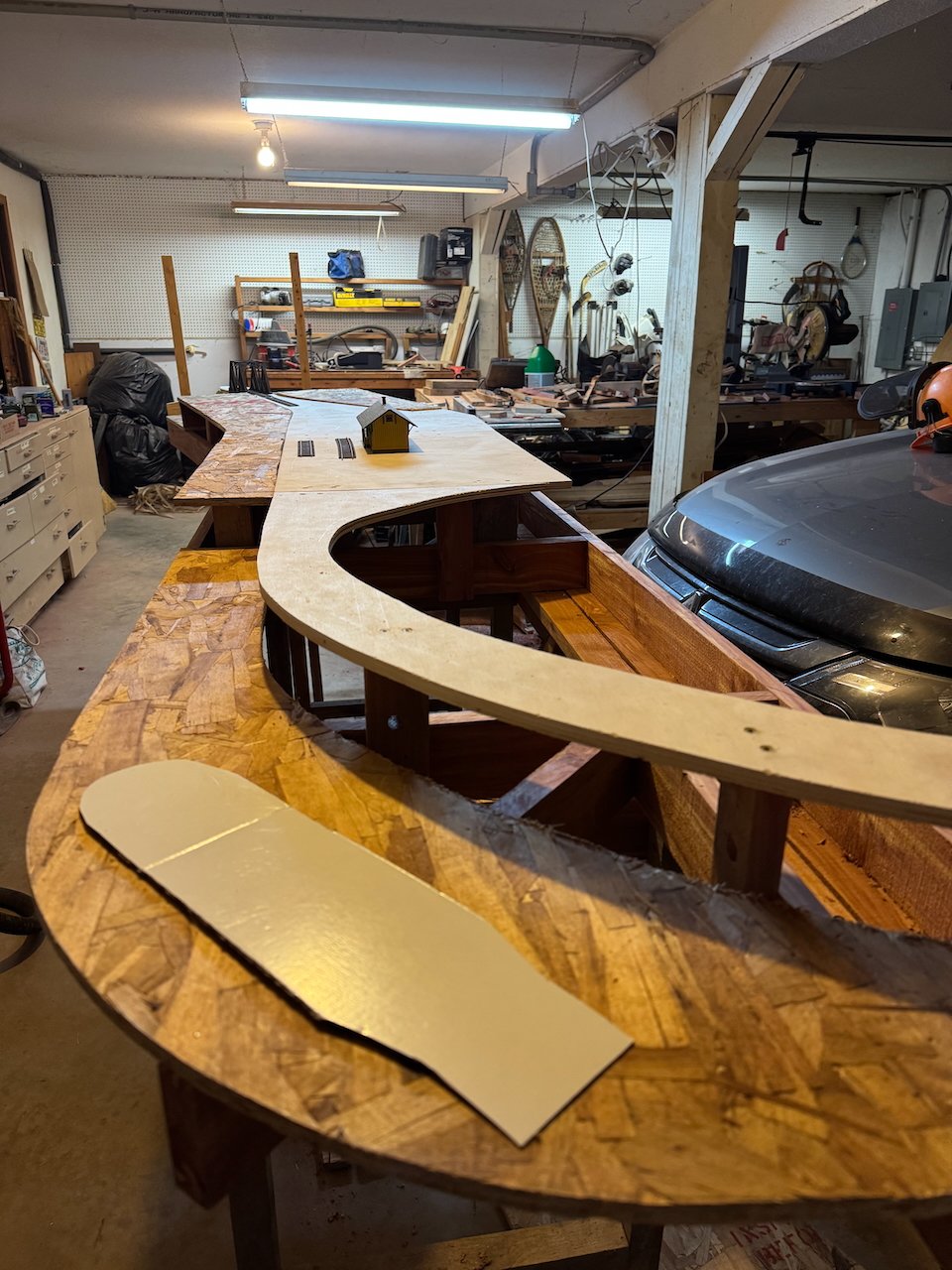
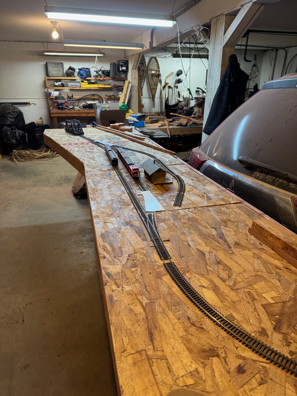
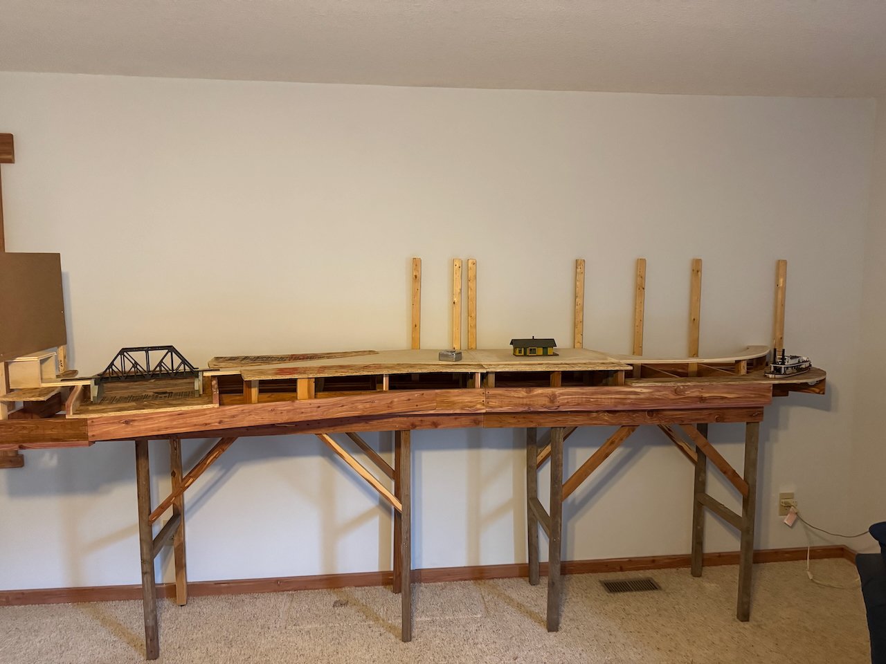
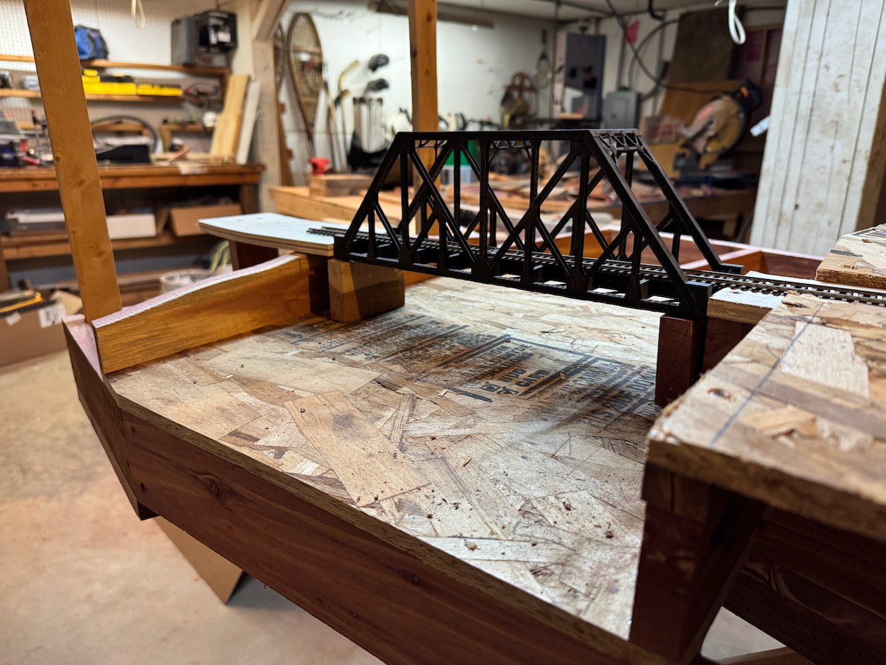
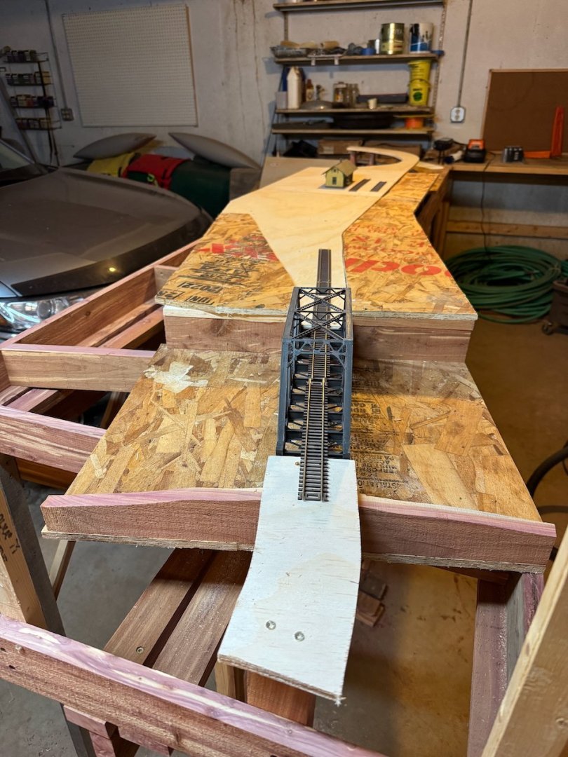
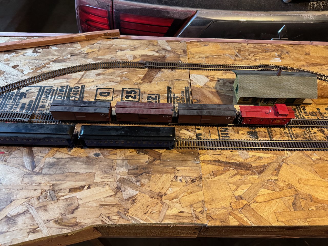
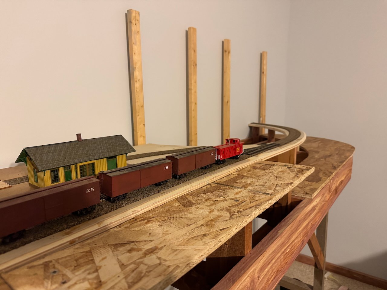
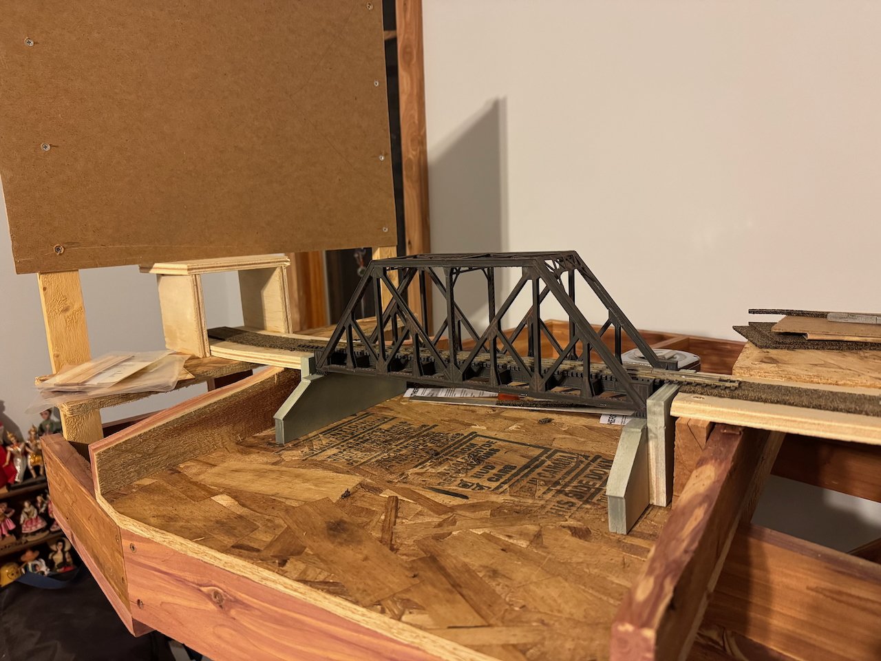
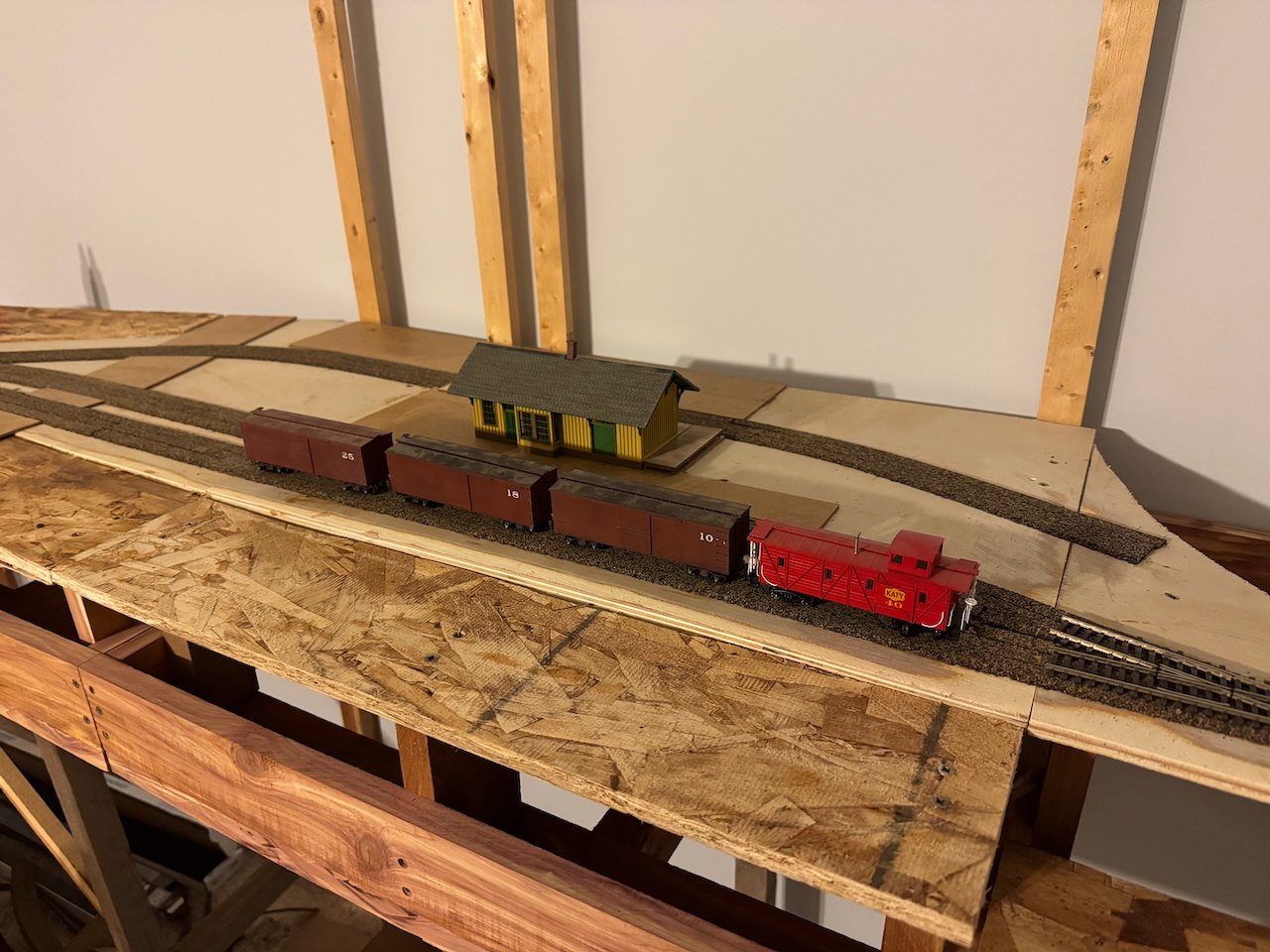
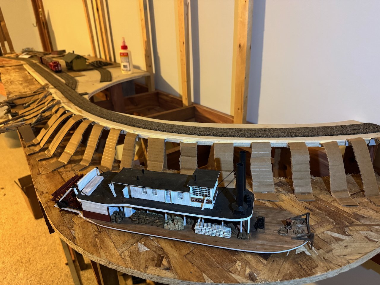
OK, let's try to catch up on the other work that's been done so far. I started trying to write up some deeper background about layout design, development, historical/geographic settings, etc. and it just got away from me, so for now we're going to focus on the more mundane physical details. The Rocheport scene is built on two modules, each 5.5' long for a total length of 11'. The depth of scene (to the backdrop) is about 2' on both, though the left-hand one curves outward to accommodate a possible future curve back around the other way, and also to add more scenic interest. One rule of thumb in model railroad planning is not to lay everything too straight; subtle changes in direction add visual interest. Here's an early view of the benchwork showing how each module is its own unit, set on top of separate support structures. They're bolted together in the middle and I can take either one off its supports independently if I want to work on it in a different setting or at a different angle (such as tilted onto its side for track wiring beneath the surface or taken outside for messy painting). If you're wondering about the wood color, most of it is Eastern Red Cedar that I cut and milled on my rural Missouri homestead farm. That'll be a theme in this project, using as much local/natural material as I can, especially for scenery. The backdrop supports are cheap pine 1x3s that I had sitting around from a long-ago project; I'm using them to use them up because they're perfect for this. The darker wood like the legs is also cedar, just older and weathered; those are reused pieces from an old chicken coop I built years ago and no longer need. The benchwork is solid framed boxes, with the actual surface being plywood supported on risers. This allows for two things: (1) scenery below track level like rivers and (2) easier access for wiring later. Here are a couple early views of transferring my computer-drawn track plan onto cheap plywood sheets (which I reused from a shipping crate rather than buying new). The joint between the two modules is just to the left of the depot. As the photos suggest, I did 95% of the woodworking down in my garage woodshop (and some outdoors when winter weather allowed). This is one of many benefits of the modular system; I can build these where all my tools are and then transport them upstairs to a more finished room, rather than turning a finished room into a construction zone for months. Once I had the exact track routes laid out, I made patterns and cut new pieces from high-end plywood to support the actual trackbed and core town areas. This ensures that the important surfaces are smooth and flat, but saves money from making everything out of good plywood. The cheap plywood remains as the base for things like rivers and other scenic areas that don't need to be perfect. Below are a few more views showing how these surfaces interact and how the risers aid in setting up scenery. Another reason to do it this way is that I can alter the level of the crappy plywood to create subtle changes in land surface even for areas I want mostly flat. If you look closely at the preceding and following photos you'll see that the crappy plywood doesn't quite line up with the flat high-end roadbed. There's a long, subtle climb in the surrounding "land" surface from below track level at the right end (near the depot) to above track level at the left end (near the bridge). This fits the actual landscape through Rocheport, where the track is a bit elevated over the surrounding floodplain at the town's east end, but goes through a shallow (but noticeable) cut as it approaches the bridge/tunnel combination at the west end. The "level" point where they're both even falls where a road crosses all the tracks, just visible at the left-hand side of one of the photos. These kind of details help keep a model railroad from looking like it's laid on a plywood tabletop. Even the flattest of landscapes, like the river floodplain this setting is, have local variations. The last photo also shows my scratchbuilt bridge abutments (good plywood airbrushed and weathered) and initial framing for the tunnel. The scene is set up so the tunnel provides a natural transition through the backdrop. Lots of railroads don't have tunnels so conveniently placed, but this one does! This has gotten long so I'll stop there. In a future post I'll show how I started developing the more complex landscape surfaces such as the riverbanks and the hills/bluffs rising above the tracks. Thanks for your patience as I catch up to real-time on this!


- 131 replies
-
- 18
-
-

-
You sound like certain members of my family if you replace "boiler deck" with "floor"... Everything looks great!
- 732 replies
-
- 6
-

-
-
- Lula
- sternwheeler
- (and 1 more)
-
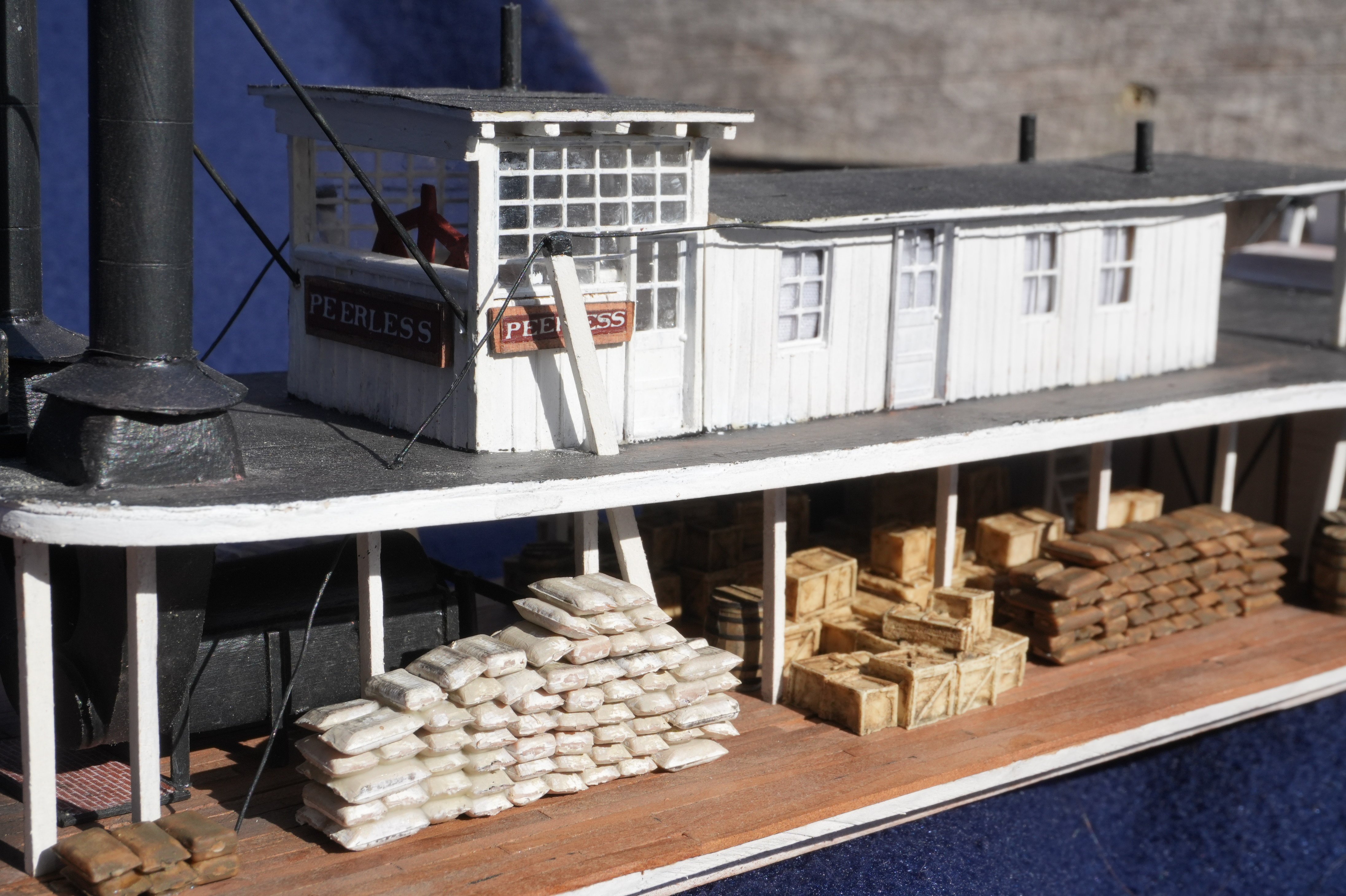
Might as well call it the boiler deck, following standard practice for steamboats, despite the nonsensicalness of calling the deck above the boiler, the boiler deck. Not sure if that nomenclature carried over into pseudo-marine harbor vessels like you're modeling here, but since your prototype is a riverboat, you can justify it. Otherwise looks great to me!
- 732 replies
-
- 8
-

-
-
- Lula
- sternwheeler
- (and 1 more)
-
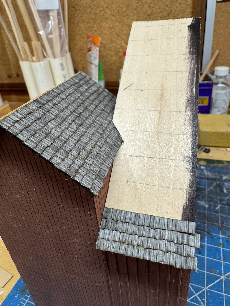
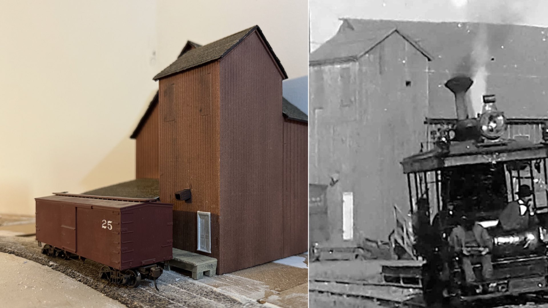
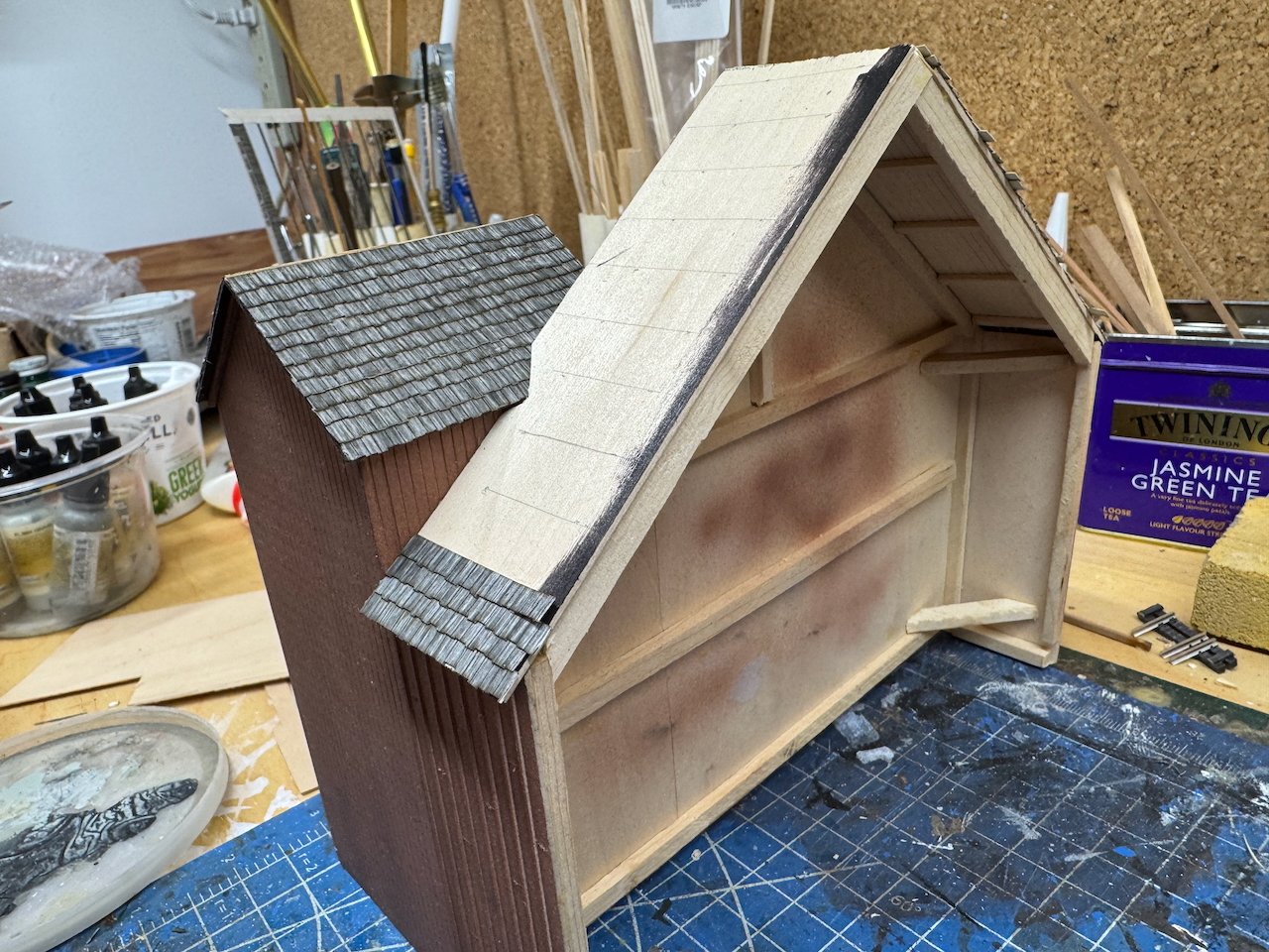
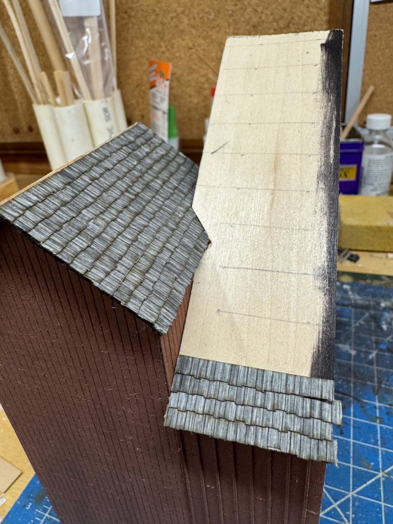
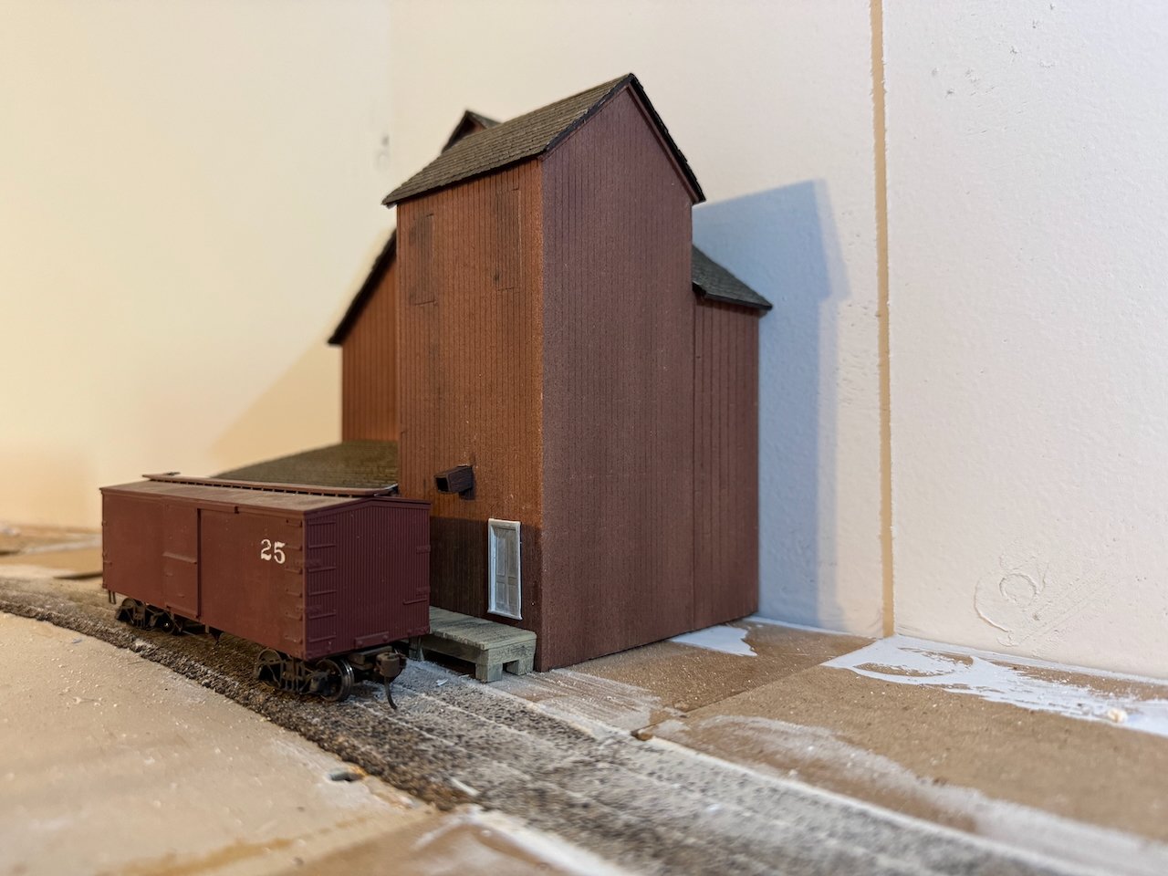
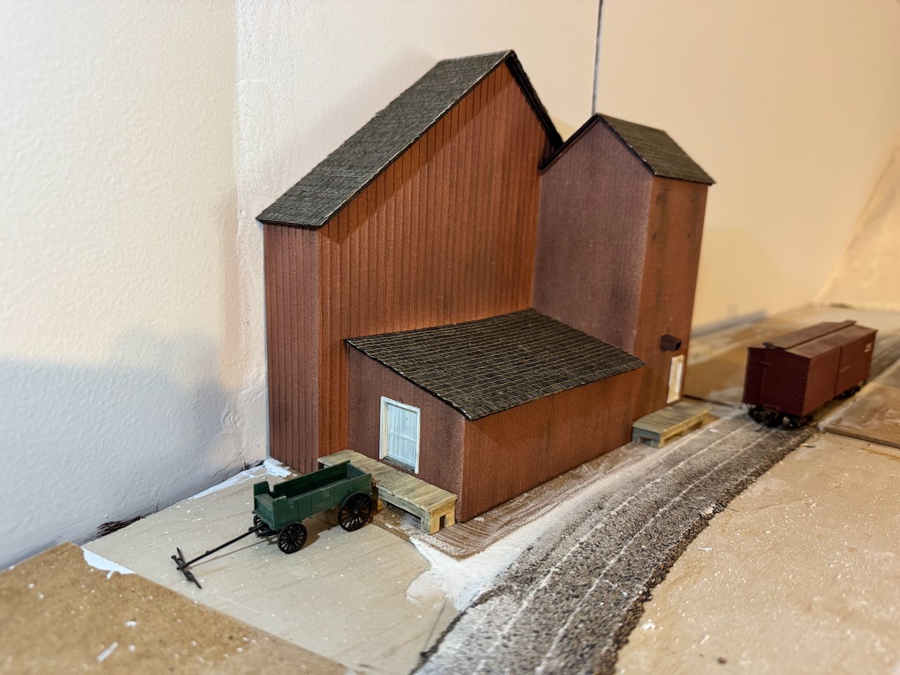
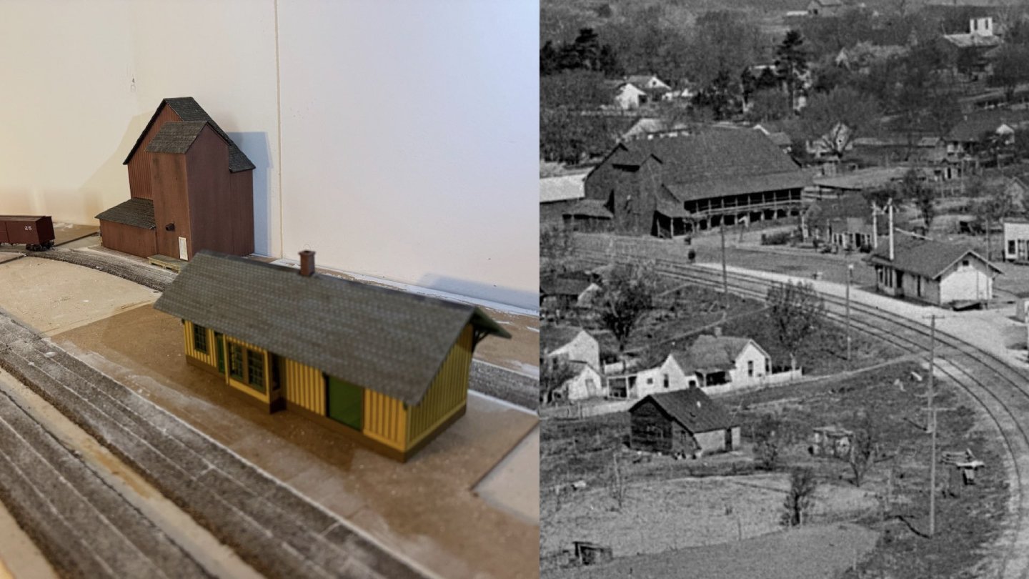
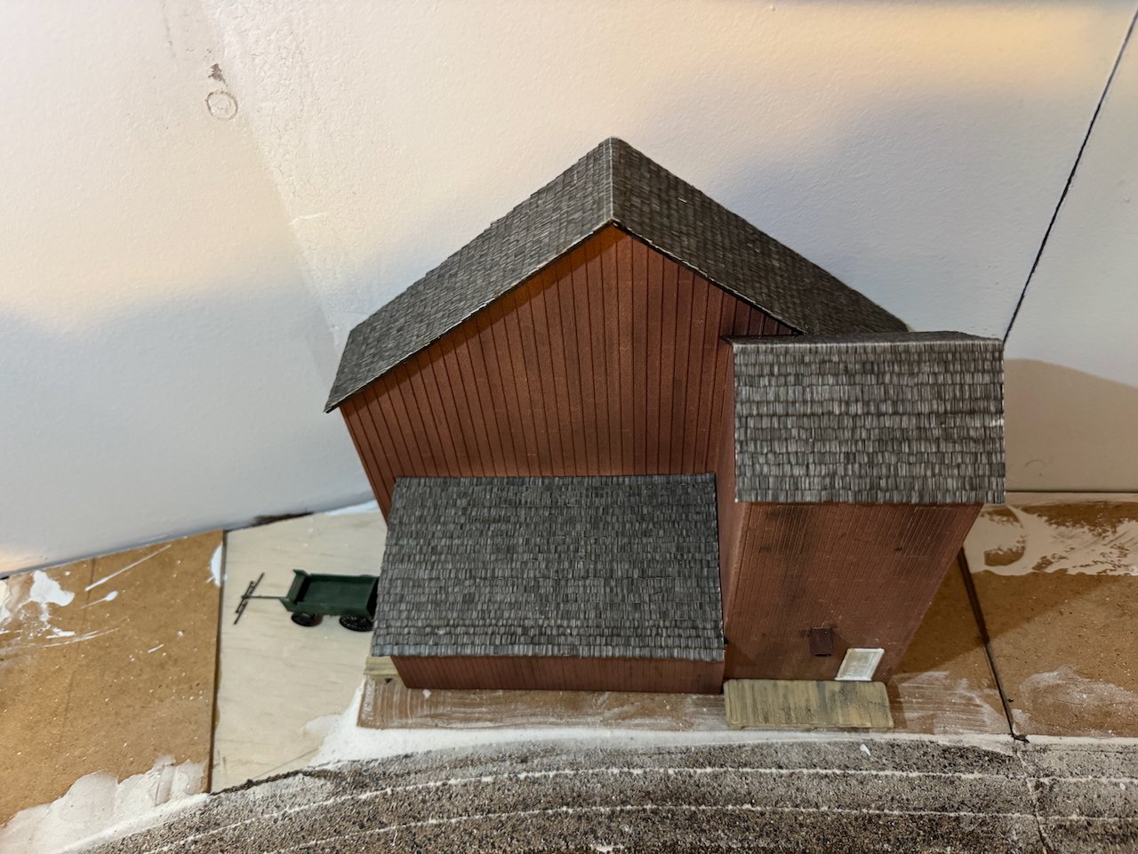
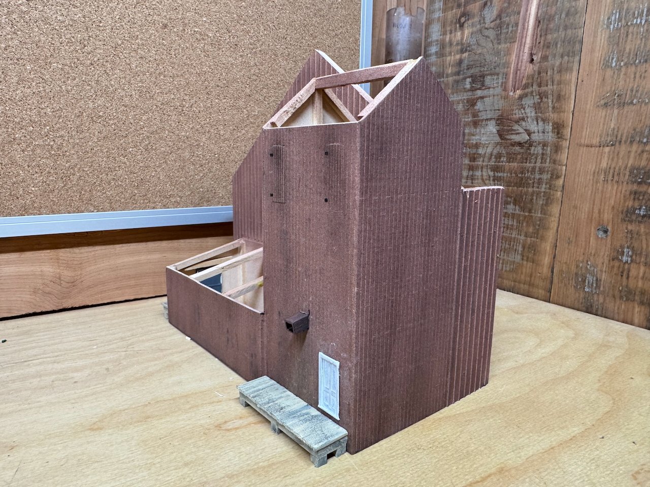
I love the idea of having a few cats scattered around, I'll definitely follow up on that long-term! Thanks! I'm excited to blend it into the scene with proper scenery. I finished the roofing today. Here are a couple more in-progress shots of the hay barn roof, showing the complicated angle where it meets the elevator roof, and a peek at the interior bracing. And here are some shots of the finished building in place against the backdrop: And a couple paired photos with the originals: I'll do a little more weathering and add a few more details. I also need to build the ramp up to the hay barn, or as much of it shows in front of the backdrop. But the main structure is done and I think I'll switch gears to something else for a bit. For a change of pace, I'll start catching you all up on the scenery work that's been done so far, and maybe delve into some of the background planning. Thanks for reading!

- 131 replies
-
- 16
-
-
-
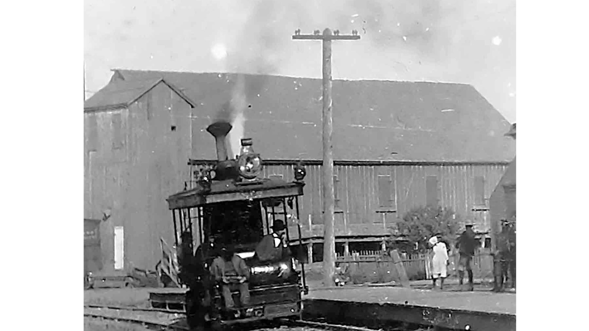
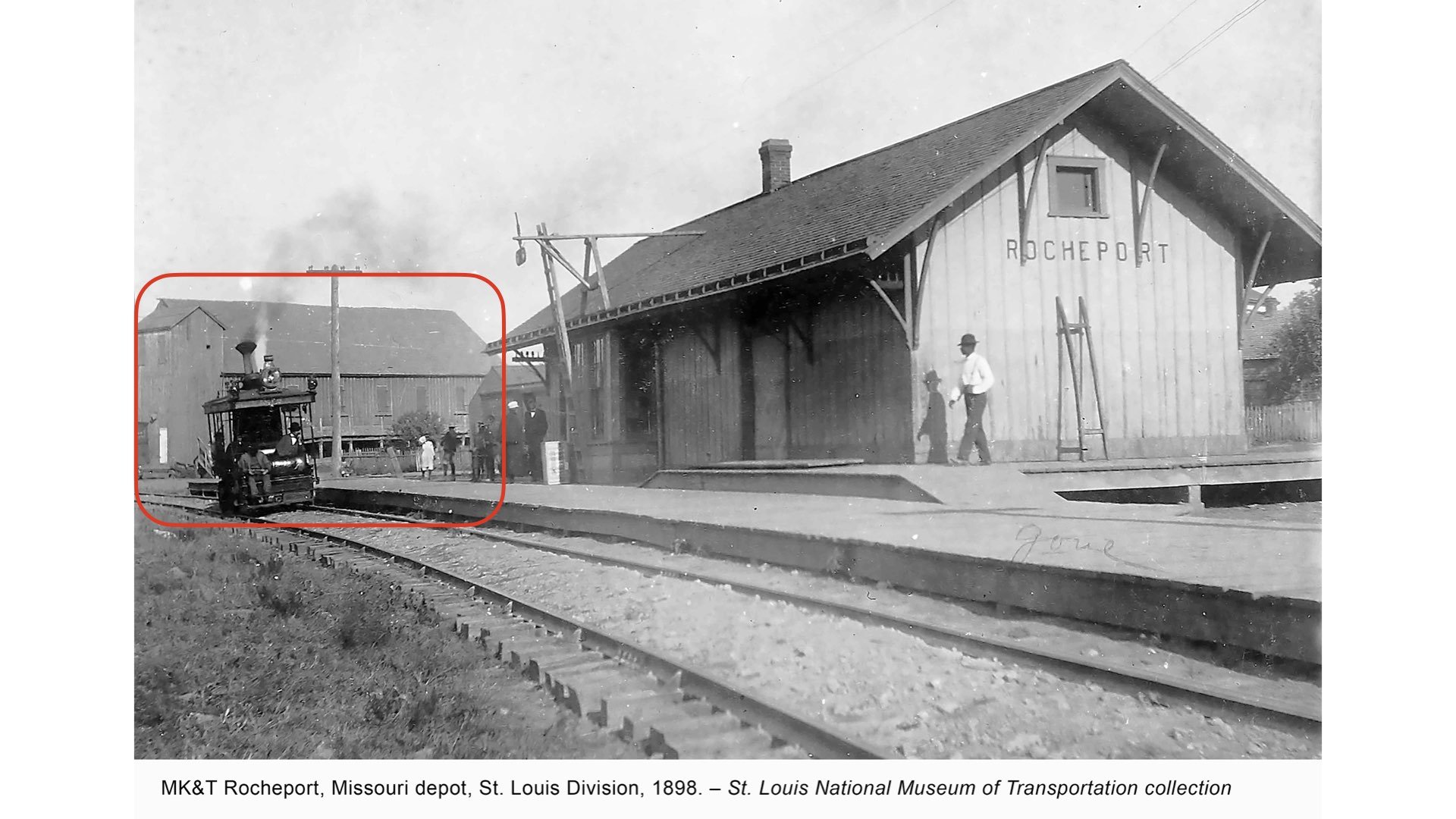
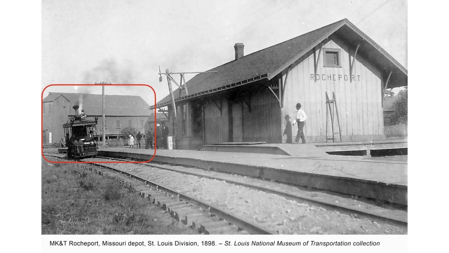
That's actually a track inspection car. It's quite significant since the Katy sent this out on a tour of this part of the system in 1898, including a photographer, who took photos of railroad infrastructure at many stops. Those photos are a core resource for me because they're almost exactly at the time period I'm modeling and cover a lot of obscure places that otherwise weren't photographed (or preserved). I don't have any plans to build one...it's too obscure and any time spent on it would take away from other progress on the broader project. Maybe in ten years or something, but not any time soon. It is cute, though!
-
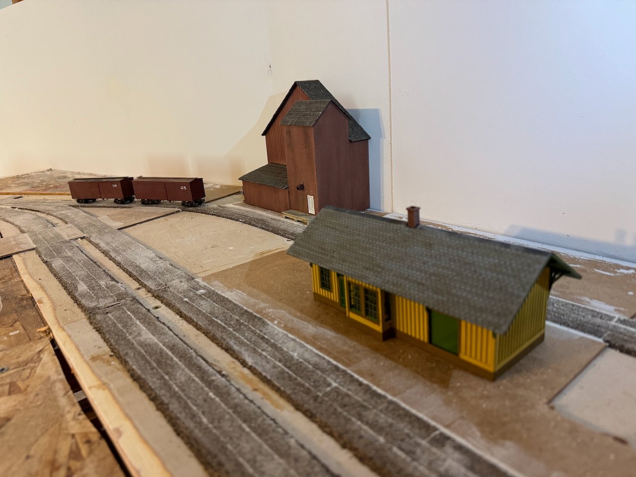
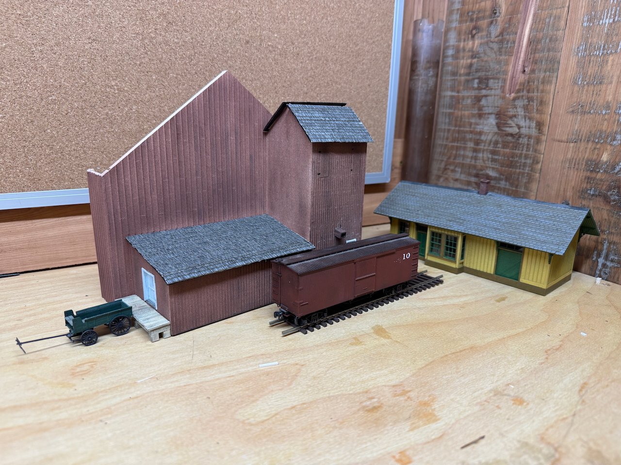
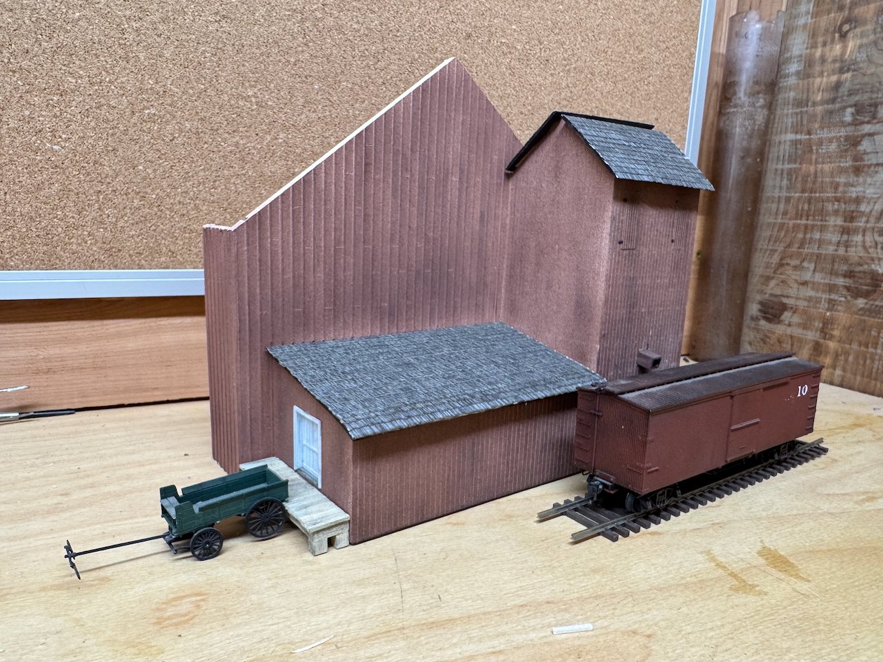
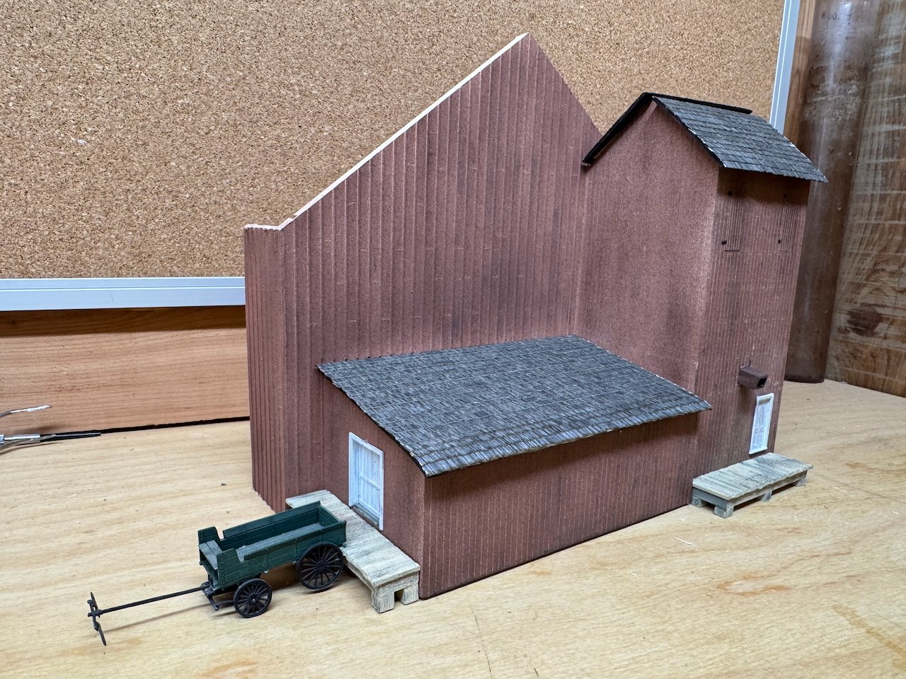
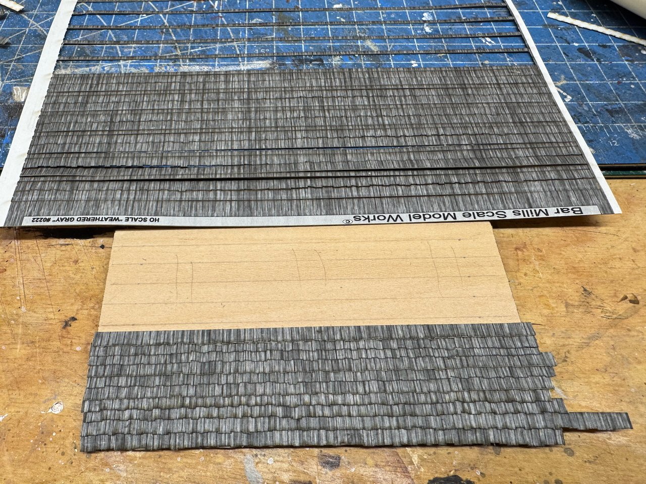
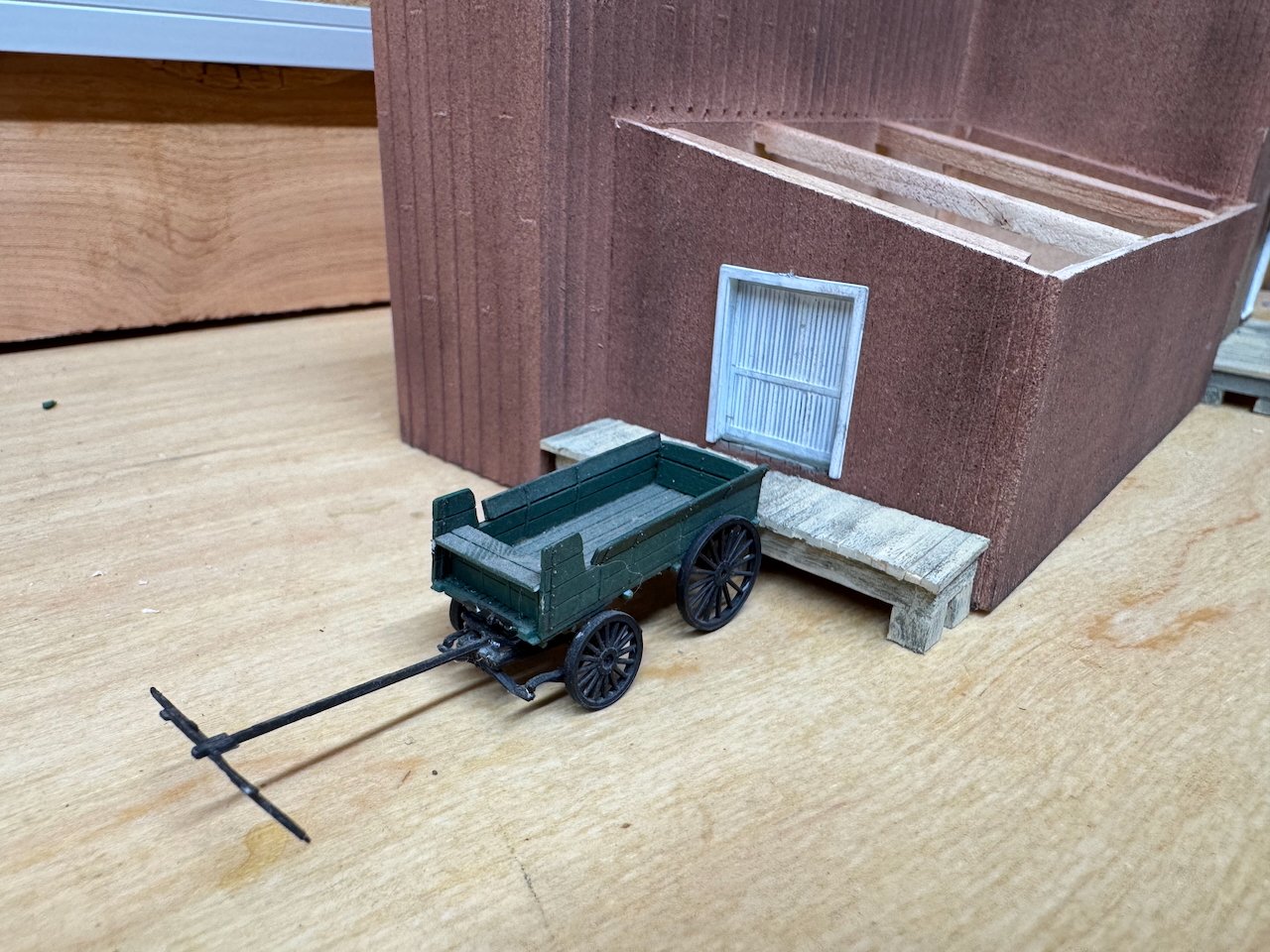
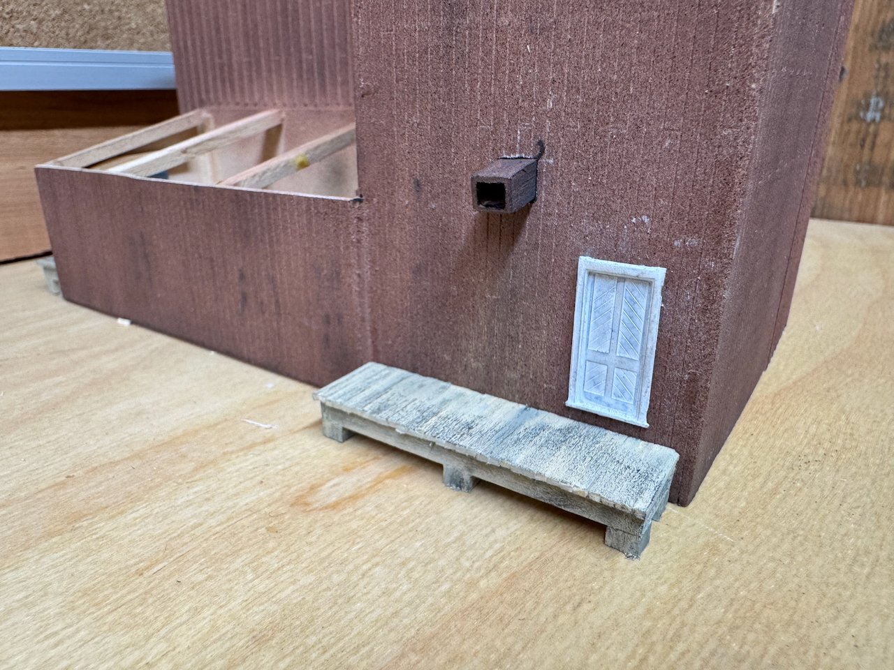
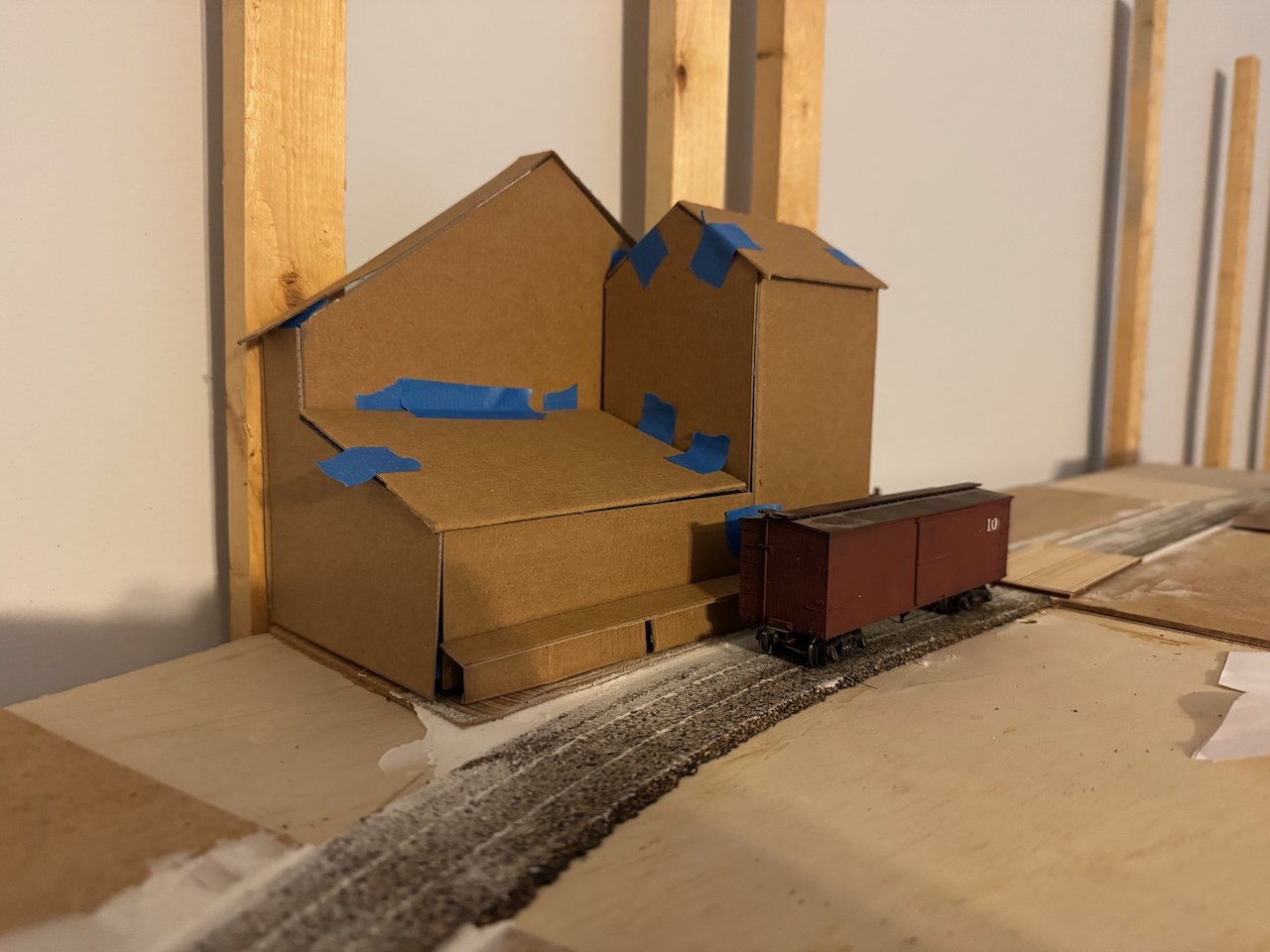
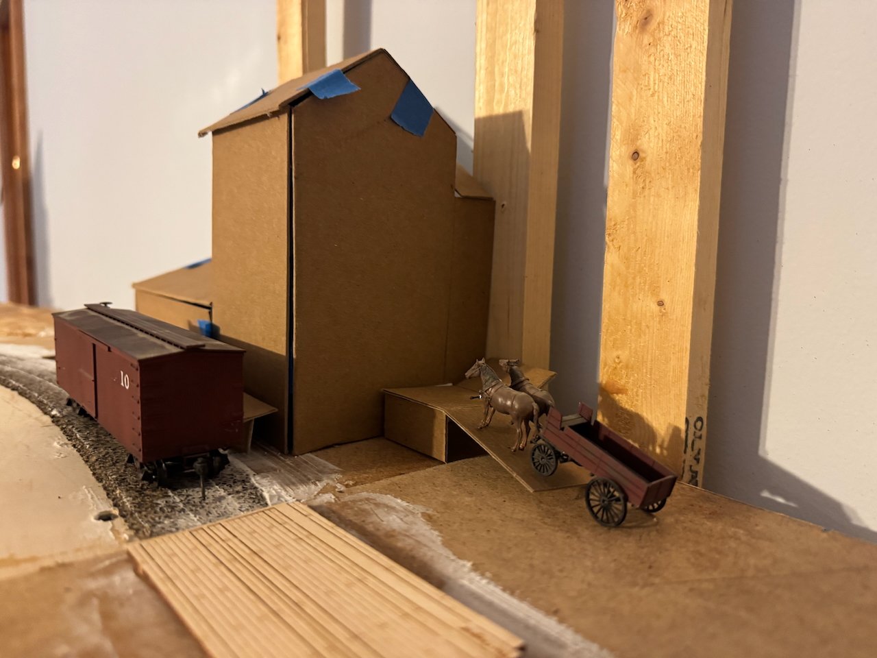
OK, enough talk, how about some more model progress! I've been putting a fair amount of time into hidden work, adding braces and stiffeners and the like to keep the whole thing nice and rigid once the paint starts spraying. By today I finally reached a point where I was comfortable firing up the airbrush, so all of the sudden it looks a lot better! I applied a thin coat of primer, then several coats of a dull red, then a light overspray of dark grey. I followed that up with some light pastel weathering. You'll notice the two loading docks. The one on the elevator's front (south side) is visible in the photos, but nothing shows the other (west) side, so I just decided there would be a loading door and dock there for visual interest. Maybe this is where farmers unload their sacked grain now. It could also be a supply/store shed. The loading docks are built from scratch, including hand-laying the individual planks. I don't mind using scribed siding for building walls but I think platforms look better when hand-laying lets things be a little more uneven. These were brush-painted with washes of various colors to create an effect of raw but weathered wood. And here are two more closeups, including a wagon for scale and setting: You can also see the grain loading chute in its withdrawn position (it would be extended for loading boxcars). Here's the original photo for reference: Next I started on the roofs. I'd already been working on these, making flat sheets with bracing underneath to keep them flat. Now I started adding laser-cut shingle strips from Bar Mills. I apply these with a thin brush of wood glue to ensure they stick. One strip at a time, with a hockey game in the background to cut the monotony: And here's how the roof parts completed so far look. These are just set loosely on the model, not attached, so they don't sit perfectly in place yet: And here it is with a boxcar in place for context: And here with the previously built depot in the background, just for a fuller sense of the consistent style of coloration and weathering I'm going for: I have to say I'm pretty pleased with how this is coming together. It doesn't look too old for a structure that can only be 5-10 years old at most, but weathered enough to not look toy-like. Nice visual interest in the lines and coloration. Fits well with the depot. But enough of my opinions, what are your thoughts? There's still time to make changes or improvements. The loading docks and doors aren't glue on yet, and neither are the roof pieces. Thanks for following along and for all your feedback, ideas, and speculation that make this a richer project!

- 131 replies
-
- 17
-
-
-
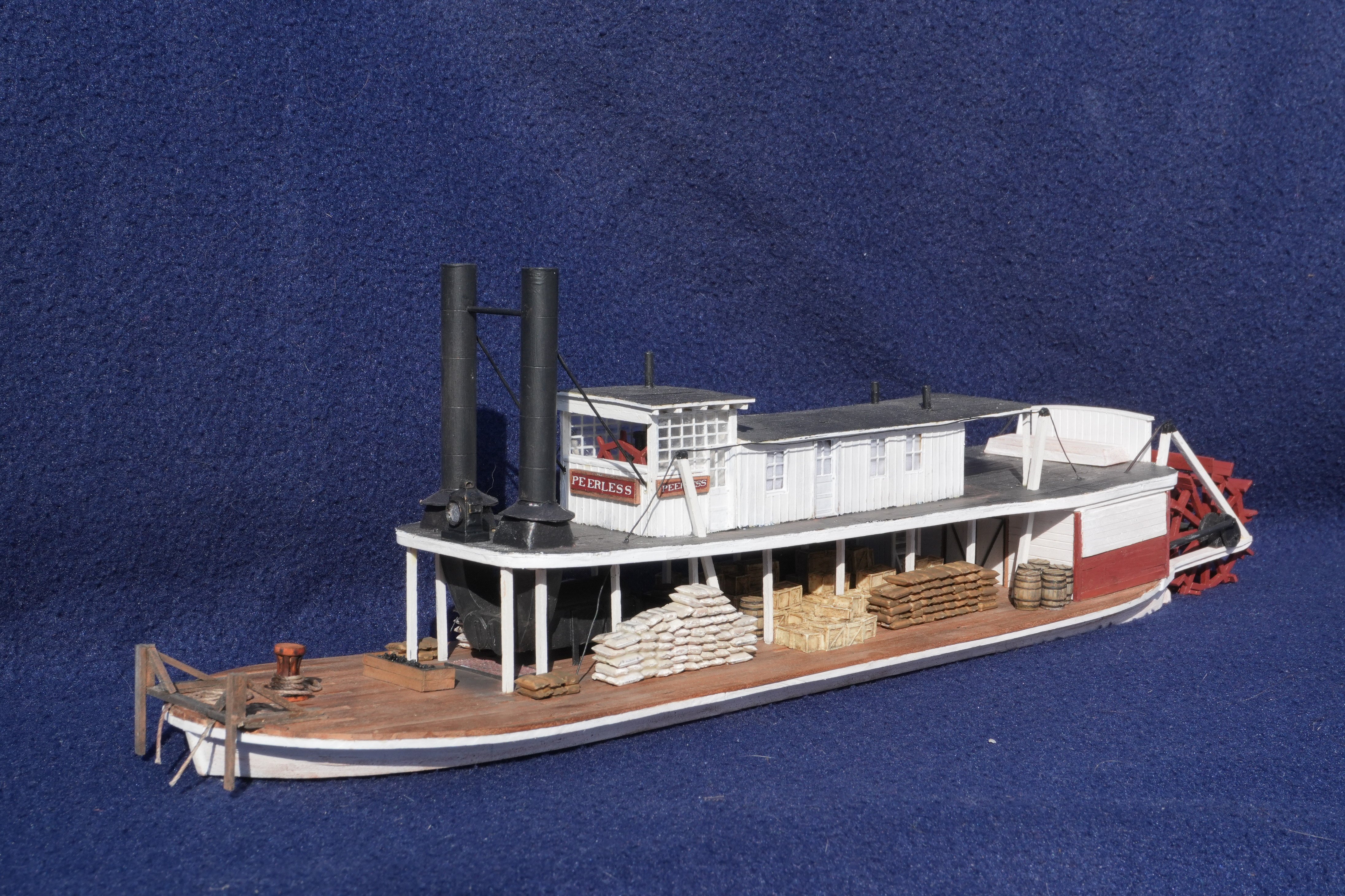
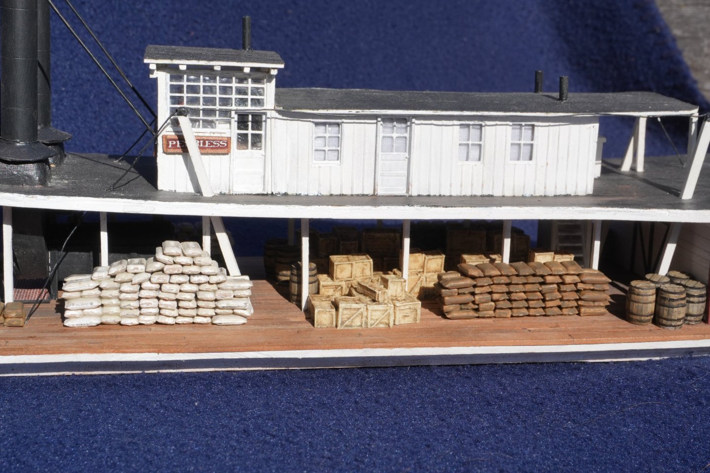
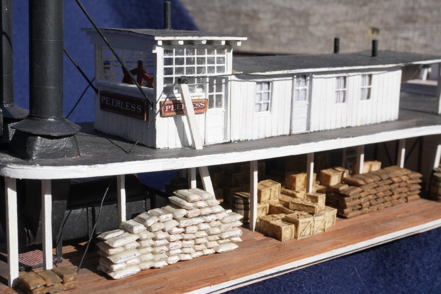
I had NO idea this mini-project would spark such interest in the esoterica of grain elevators! And it's sparked me to read up more on the subject than I ever thought I would for what's nominally a minor background structure in a much larger project. But this also shows why people get drawn into model railroading; it encompasses such a wide area of intellectual interest that there's something for almost anyone. Yep, that's the Katy Trail all right. Glad to bring back memories! Yep, we hardy pioneer stock have frontier innovations like basements and spare bedrooms! Wait until I share the full track plan, this is about 20% of it. I would guess steam. We had steam-powered mills and other industries by the mid-1800s, so it's easy to imagine even a small-town elevator in 1900 having a simple power plant running a coal-fired boiler or some such. The interesting thing is I don't see direct evidence of it in the photos I have, but it must be there somewhere. Maybe hidden behind the hay barn? (more on that in a minute) My initial impression was that grain was still handled and delivered locally in bulk, but I can't prove it. Obviously grain could be shipped in sacks, as seen in the photos of Peerless loaded down with grain sacks, but it wasn't done this way on railroads in 1900. So I can't say whether the steamboat-borne grain was sacked and farm and brought to the vessel, or brought to a central receiving point and sacked there before being loaded on the vessel. So the same would apply to this elevator; maybe local farms were sacking grain for local transport and the sacks were just getting emptied into a chute at the base of the elevator. Most resources I can find online "start" well after this era, with more modern technology, and I'm having difficulty finding details for earlier periods. As for the ramp, it's possible, but a close look at its geometry suggests that it doesn't reach the full second level until well behind the elevator (look closely at the image without a ramp roof), so it'd be an awkward delivery point to shuttle the grain (sacked or otherwise) from there back to the elevator. And why would they bother, when ground-level (or below) delivery was ubiquitous in most elevators? This leads to a broader point. My impression is that the elevator was built first, then the hay barn tacked on shortly thereafter. My main argument for this is how the two parts of the structure have very different siding; they LOOK like two different buildings, rather than one unified structure. The elevator has very smooth siding, like plain boards, while the hay barn has what looks like a coarser board-and-batten pattern. That's certainly what I did on the model, to recreate the effect of the two looking different. But I can't prove their relationship. The relevance here is that if the elevator was built first, it may have had to rejigger its receiving area (which would likely be on the back side of the structure based on normal American practice), where the hay barn ended up. But no inspection of either photos has turned up anything I can clearly identify as the steam plant (e.g. a smokestack) or a clear delivery point for wagons. Basically all this is a shrug, as interesting as it is, because I can recreate the physical appearance of the trackside part of the building pretty accurately based on the two photos, and the rest is fun esoterica but doesn't affect the actual model. What matters most is that it looks right in the background and acts as a place for local freights to spot boxcar traffic.
- 131 replies
-
- 11
-
-
EG, that makes a ton of sense and also explains the paired doors and their location on that wall. Awesome! I'm still not sure where the wagon unloading would have taken place, as the ramp up to the hay barn seems to block the right wall of the elevator, the big shed blocks the left wall (as viewed from the tracks), and the hay barn blocks the rear.
-
You could always choose to add and rig the Bounty Launch's sail yourself, thus putting a toe into the scratchbuilding waters. It certainly had one!
-
Lynn, was that quote you provided generated by the Google AI? It seems a little off to me. Grain isn't loaded into elevators through doors at the top of the headhouse. It's input into the elevator structure at or near ground level and then hoisted up by machinery in the head house, where it's then distributed by gravity into various storage compartments. The quote given sounds like a classic AI hallucination to me, misunderstanding what it's "reading". In other words, there's no way those doors on this elevator were how the grain got into the elevator: there's no mechanism by which the grain would be raised up outside the structure, then poured through those doors into the structure. Instead, there would have been a loading point somewhere where farmers dumped their grain into a chute/hopper that then used internal elevator mechanisms to hoist the grain up to the top of the tower (using machinery in the headhouse), then the grain would have been directed into one or more vertical bins inside the structure, and from there it would have been gravity-fed into boxcars using the little spout you can see on the side of the buildings. I'm definitely not sure where the farmers' loading point was on this structure, given the photographic evidence, but I'm not too worried about it as I'm following what I can see pretty closely and the most important detail is how the grain gets into the boxcars (and that's clear).
- 131 replies
-
- 10
-
-
Ken, I did think about that. But I feel like normally those sorts of access doors are on the other wall, where the roof peaks. I've seen those in many historic mill structures, for example, and they're always as high up as they can be, probably so they can use the central roof beam for strength. Barns are the same way; you always see the extended hay loft access on the high side. Whereas this structure has those doors on the low wall below the eaves of the roof, not on the high side. So I dunno. But there isn't one on that other side, so maybe you're right?
-
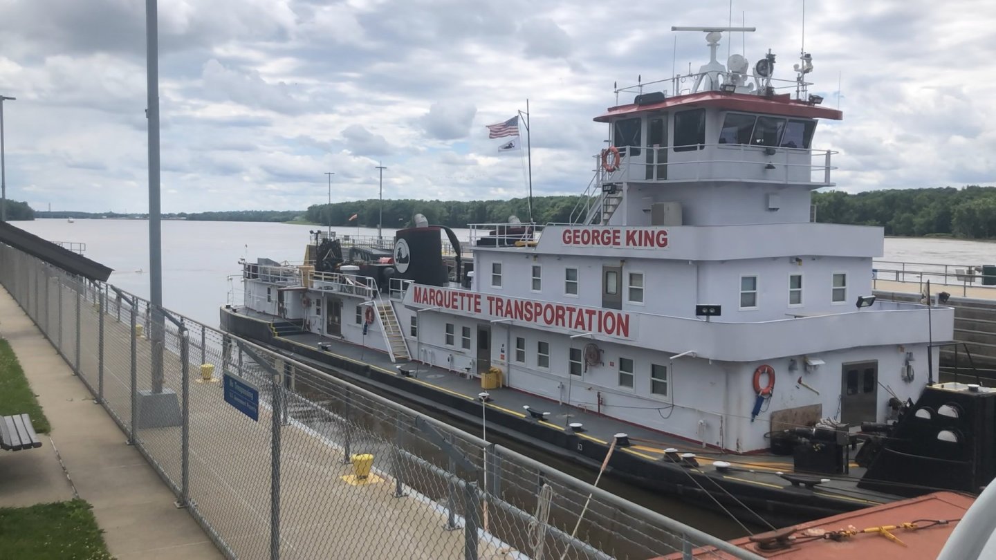
How exciting! All this progress looks great. To Eberhard's question, here's an image I took along the upper Mississippi last year, showing a similar towboat using single lines to multiple bollards to hold a tow fast.
-
I could easily advise both ways. My first few nautical models are pretty cringey to me now, but they all represented progress on a path. As great a resource as MSW is, it also sets one up to make constant comparisons with the "best" one sees here, and to judge one's own work accordingly. On the other hand, there's no shame in recognizing that one wants to do better and maybe a different path would achieve that. I've built that longboat and agree that it's surprisingly tricky in places, though again as long as your personal standards are properly calibrated it'll be a good learning experience. Another option would be something in a larger scale so you get practice in some of the basic skills without the tinyness. For example, I got a lot out of building the Model Shipways Bounty Launch. There's really no wrong choice here as long as you're comfortable with it!
-
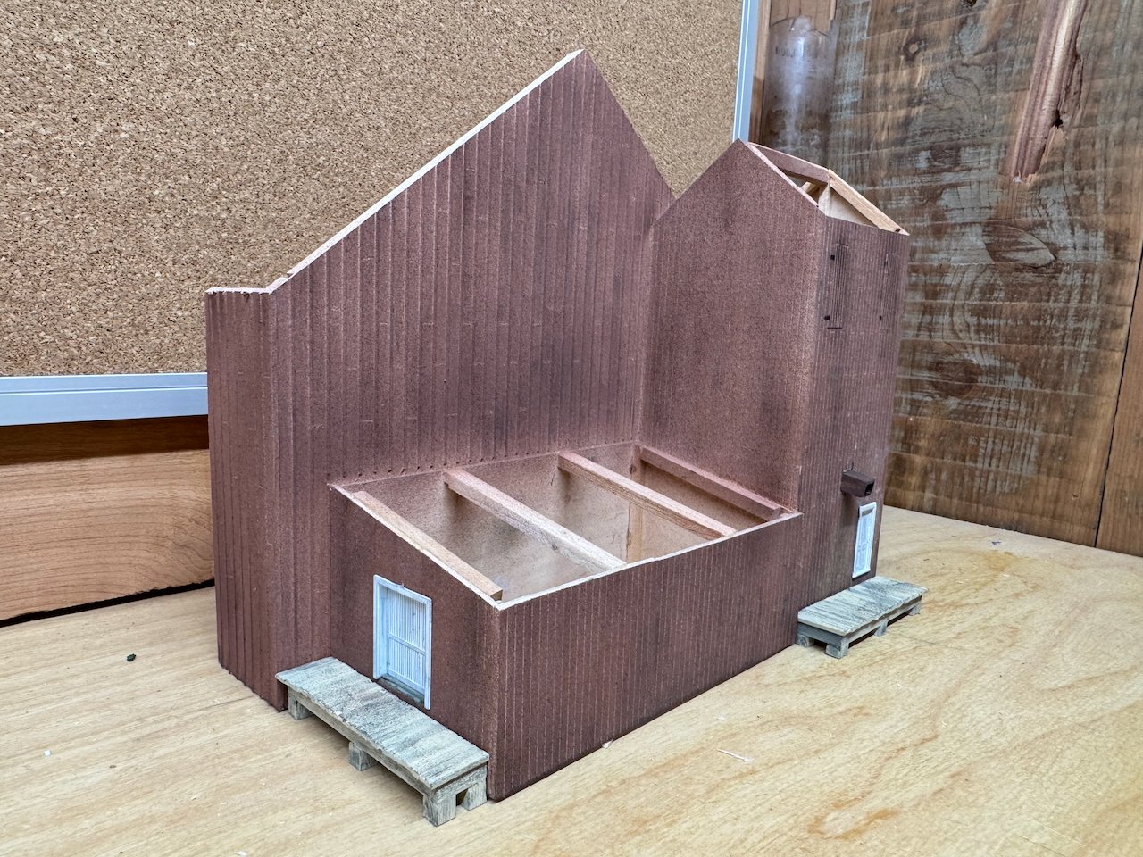
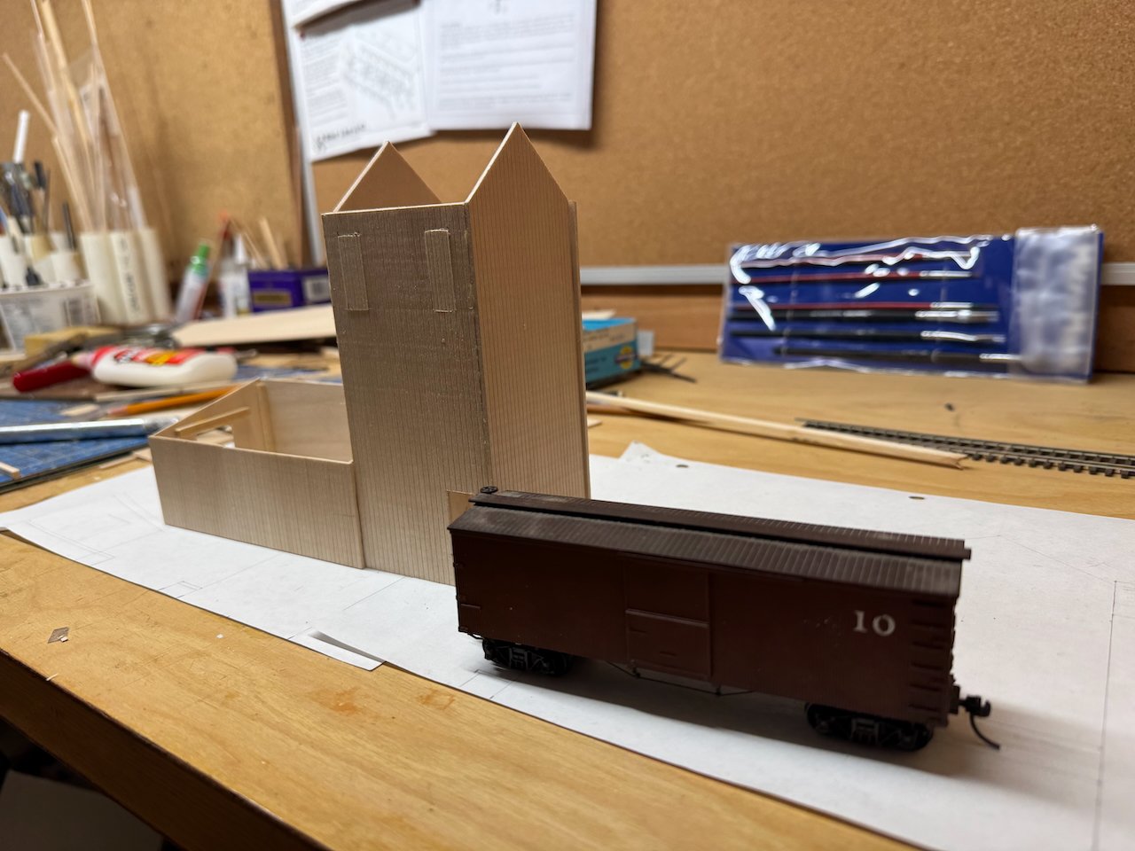
More progress on the elevator hay barn, which is now a unified structure: I scored a pattern of plank ends into the elevator's siding; the goal is for them to show up faintly after painting, just enough to suggest this wasn't built with 50' planks. In writing this I realized I need to do this on the hay barn's front wall, too. This doesn't look all that different from the last photo, but there's a lot of work you can't see, like internal bracing (especially within the elevator), and getting all the constituent parts lined up into a nice whole. Next will be attaching about 1" of depth to the hay barn and setting up whatever roof framing I want. At that point it's ready for airbrushing, followed by roofing. If you're wondering, this structure would have been fairly new in 1900, so the goal is for it to look well-kept with just enough weathering to not look toylike. Somewhat different from the usual rough neglect we modelers often like our working models to have. So no missing planks or shingles, no peeling paint, no repair patches, etc. By the way, that brief preceding conversation about what the upper doors are for...that's exactly why I decided to go ahead with a build log. There's just such a richer experience to building models when you can benefit from others' insights and questions. That exchange didn't even change the model, but it makes the model richer to understand more about the prototype. Thank you!
- 131 replies
-
- 19
-
-
There's only really three geometries to attach a barge to a power source: front, rear, or side. Towing behind the power source didn't develop because early vessels were sternwheelers, so the wheel gets in the way. Even when propellors came along, same problem: tying up a load at the stern messes with the propulsion and rudders. Whereas towing on any kind of line gives you almost no control on a winding river. Side can work, but you need a wide channel for that, and at the scale of most North American loads, you wouldn't be able to do more than a few barges. Plus it puts a lot of shear stress on however you attach the load to the side of the vessel. Front gives you all the room in the world, keeps the load away from the propulsion and rudders, gives you a lot more control, lets the force be a direct push into the load, and lets the pilot watch the load. How many people pull a shopping cart instead of pushing it? The fascinating difference I've seen between North American and European riverboats is that North America seemed to develop separate vessels for power and load (think towboat with barges) whereas so many European riverboats are combined, like small freighters. No idea why that difference developed. Eberhard?
- 732 replies
-
- 5
-
-
-
- Lula
- sternwheeler
- (and 1 more)
-
Keith, that all looks so good! I have one question: in my eye, the angle of the stairs looks a little shallow (close to 45º). So many shipboard stairs are quite a bit steeper, to save space, and my eye says that those on the original Lula are also steeper (more like 60º or more). Also, at the current angle, they look like they'd need some vertical bracing halfway along because there'd be some bounce or sag in that long horizontal run. To my eye, on-board stairs like these should straddle the line between ladders and "normal" household stairs. So I'm curious about the thought process here. And since you said they're not attached yet, it's a good time to ask!
- 732 replies
-
- 7
-
-
-
- Lula
- sternwheeler
- (and 1 more)
-
Paul, that occurred to me after seeing Keith's photo, and my first thought was why doors and not just large windows? But then it occurred to me that doors are easier to open when needed and seal when not, without the added expense and fuss of glass if the light isn't needed. I still remember my high school physics teacher showing us how to make a cannon out of nothing but a cardboard tube, sifted flour, and a match. Good stuff. So I bet you're right.
- 131 replies
-
- 10
-
-
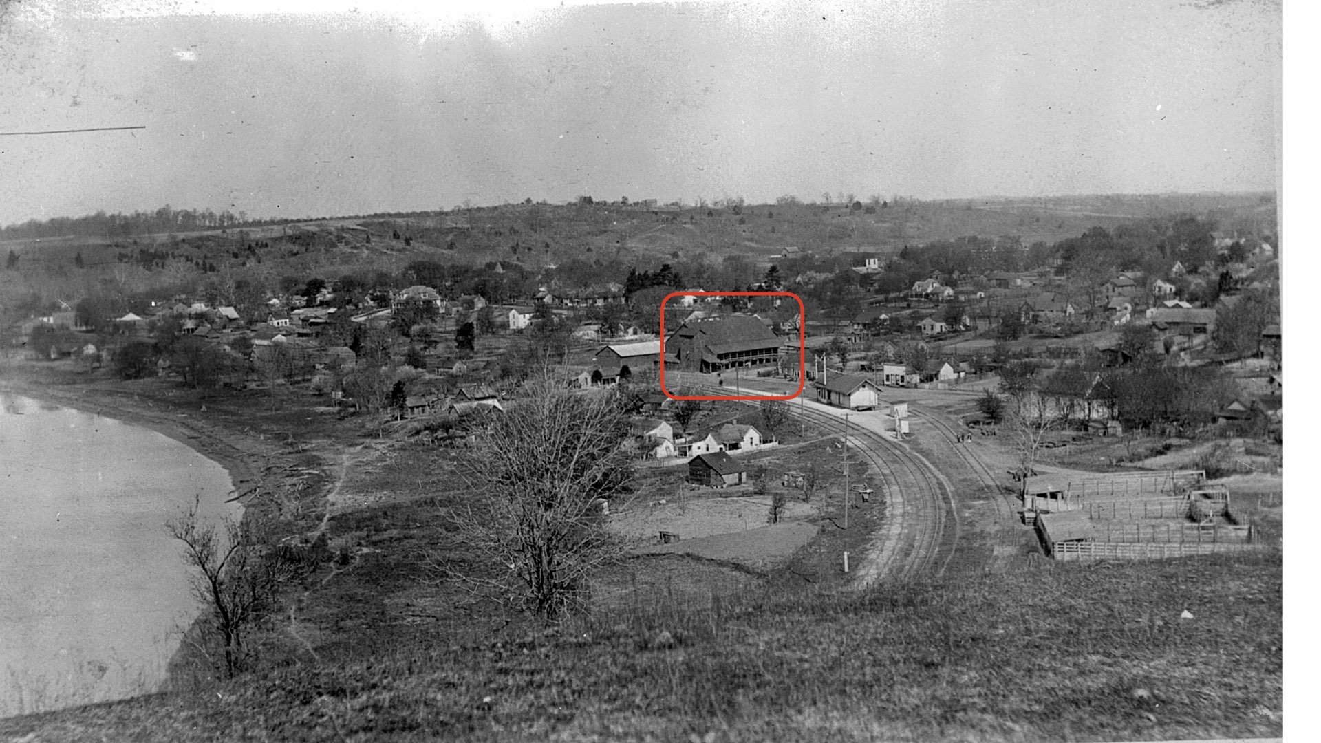
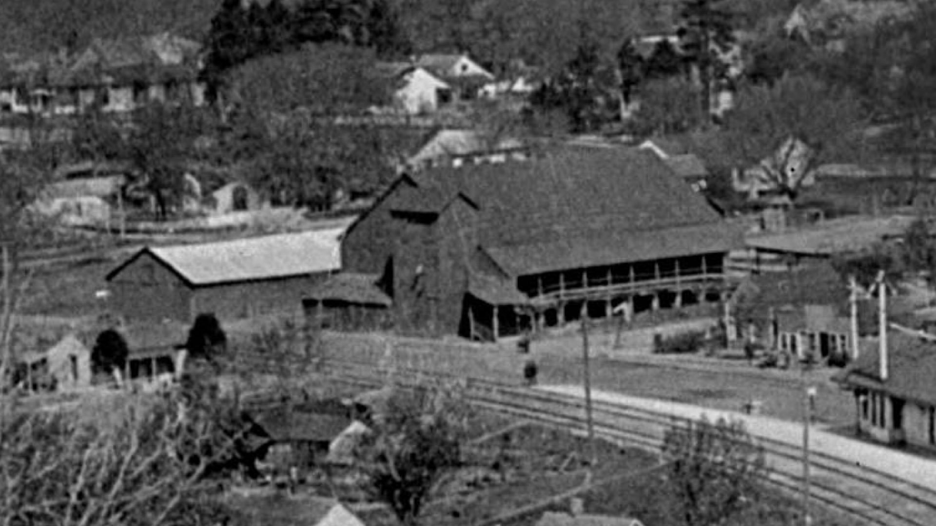
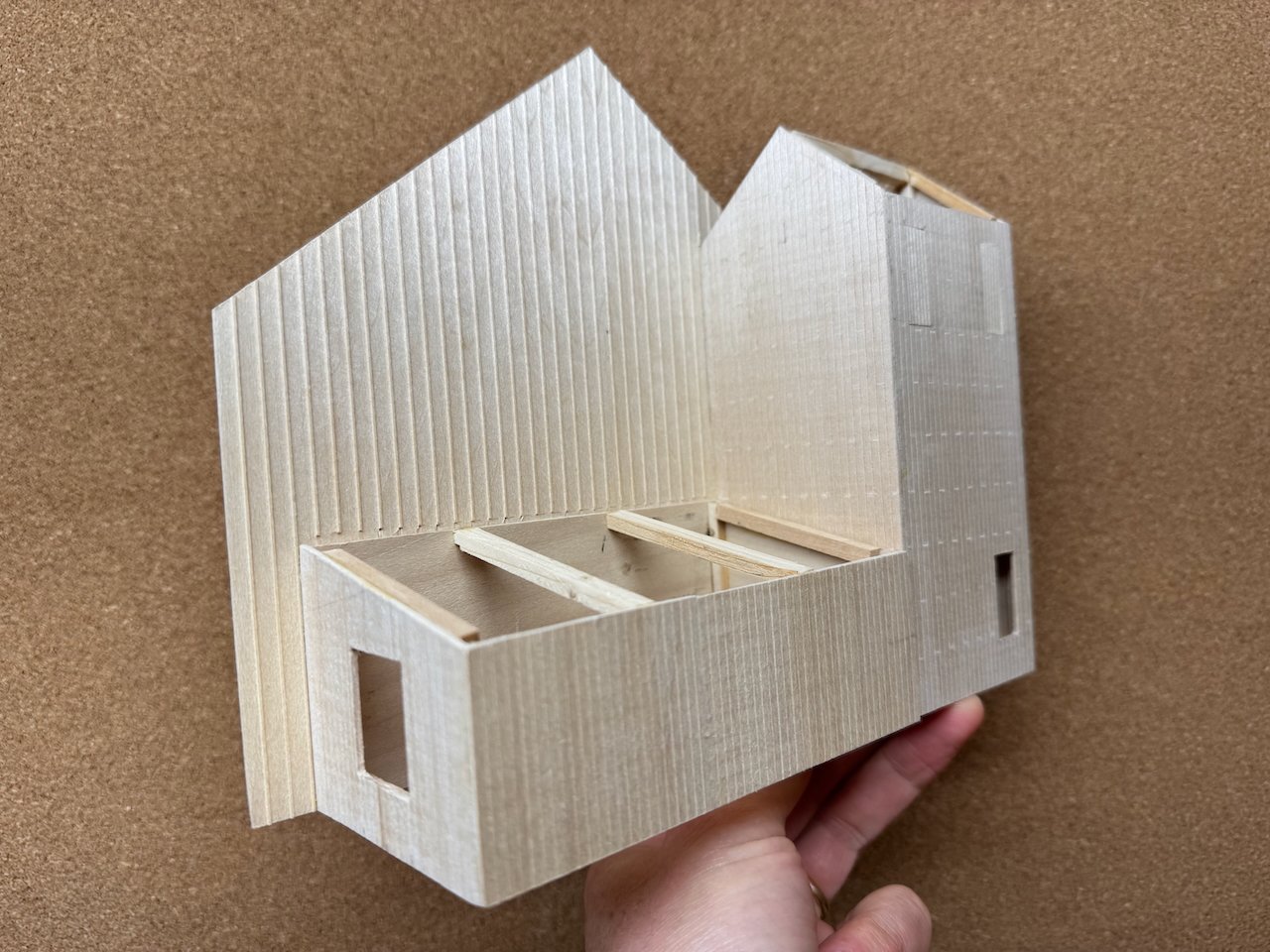
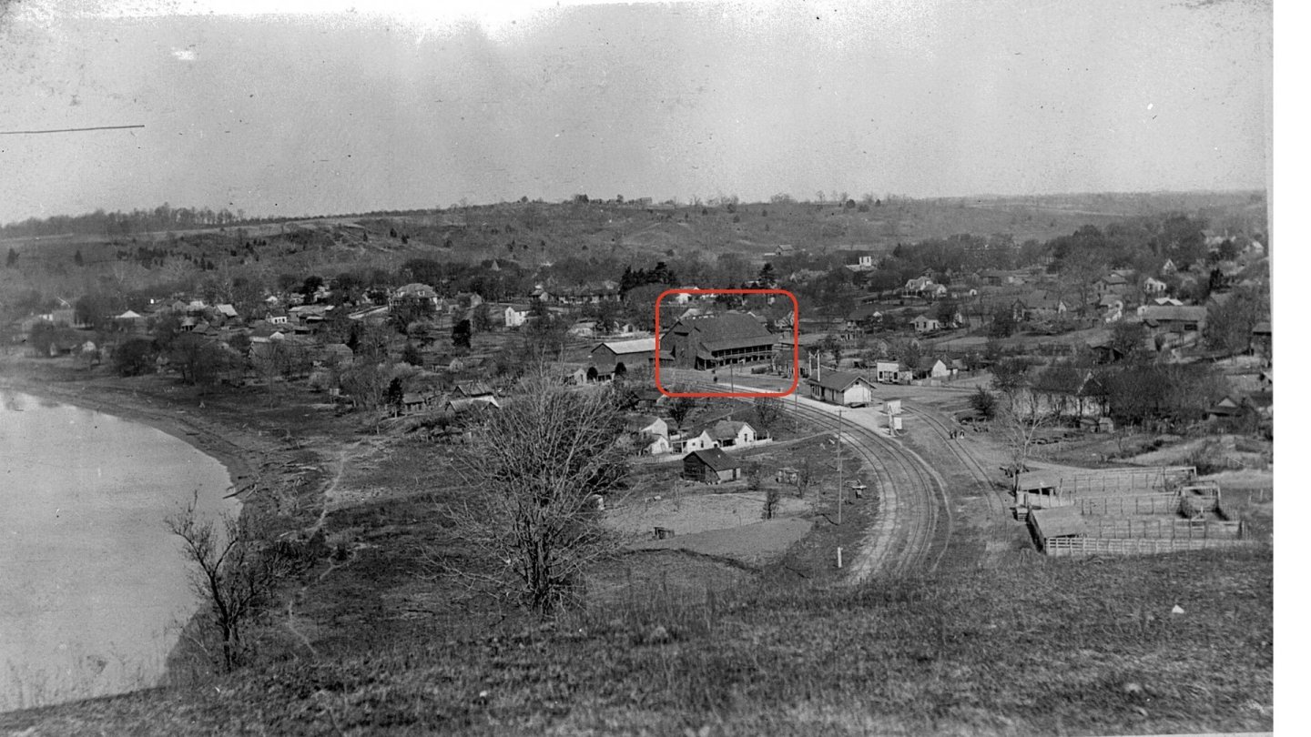
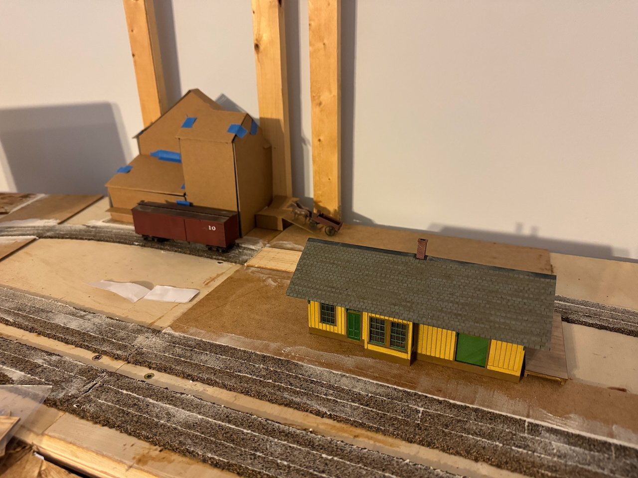
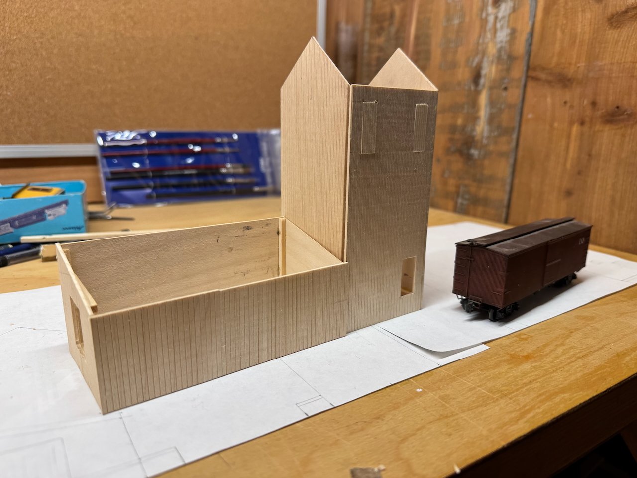
There's so many different paths I could take in starting to catch you all up on the context for this project that it's a bit overwhelming. Do I focus on the model-railroad-oriented process of track planning, how we design the track layout to allow realistic operations? Do I focus on more historical details of the railroad in general and Rocheport in particular? Do I focus on building the benchwork and early scenery forms? All of that takes time to write up, and you all are here for the modeling, so let's start with a simpler narrative, the current building I'm working on. This is a really interesting-looking structure seen behind the depot in only two photographs that I've found, shown below with zoomed-on crops. The front part of this building is clearly an early grain elevator, with a loading spout set to extend down to the door of a boxcar on that spur. This is the era when grain was shipped in boxcars with planks nailed over their open doors. But what's going on with that huge building attached behind the elevator, with its massive interior, and even weirder, a wide ramp leading up to a second-story "porch"? In the first photo (1898), the ramp and porch are uncovered, while by the second photo, I think in the 19-teens, there's a roof over that whole thing. I finally got the answer from a very helpful contact at the Katy Railroad Historical Society. While the front part is indeed a grain elevator, the back part is a massive hay barn. The Katy did a serious business in shipping Texas cattle north, and built a series of huge barns to store the hay needed to feed these cattle on their journey to processors in Kansas City, St. Louis, and Chicago. So that's a hay barn, and the ramp allows loaded hay wagons to drive up to the second floor and deliver hay into the barn, probably through the doors you see in the first (uncovered photos). Very cool! You'll see Rocheport's small stock yard in the lower right of the wider-view photo, just down the street from the hay barn. This also shows the local economic impact a railroad could have; even a small town like Rocheport would benefit from this major source of local farm revenue coming from the railroad. I wish I had room to model this building in its entirety, but then the scene would extend way too far back. As it is, I can only fit a narrow part against the backdrop. So I did some estimated measurements, using the usefully placed boxcar in one photo for scale, and came up with a representative design that fit my space. I then built a cardstock mockup to see how it looked visually behind the depot (that project is a different topic). This told me that my original elevator tower looked a little too squat, so I redrew my plans to make it a bit narrower and slightly taller. I also removed the loading dock I'd somewhat speculatively placed there, as I don't like the look and it doesn't fit the curve of the siding. Once I'd redrawn my plans, I started building. This is really straightforward after years of complicated shipbuilding curves; lots of nice straight walls and square corners. I'm using pre-scribed siding and styrene castings for doors. Here are two quick photos of the progress so far. That's all I've got for now. I'll keep following up as I work on this. One fun question is what those two doors way up on the elevator's face are for? They're clearly visible in the photo, so I included them, but danged if I can figure them out.

- 131 replies
-
- 20
-
-
I mentioned "Katy" as the railroad's nickname but didn't give the backstory. The official story is that the company's stock symbol was KT and that's where the nickname came from, but I personally think it also just developed organically because it's so obvious.
-
Keith, I'll give a lot more details of the full layout plan in a future post, but the Rocheport section measures about 2'x11'.
-
I'm briefly hijacking your log to announce that you're getting your wish. I posted the first wordy intro to that project in the non-ship section of MSW this morning.
-
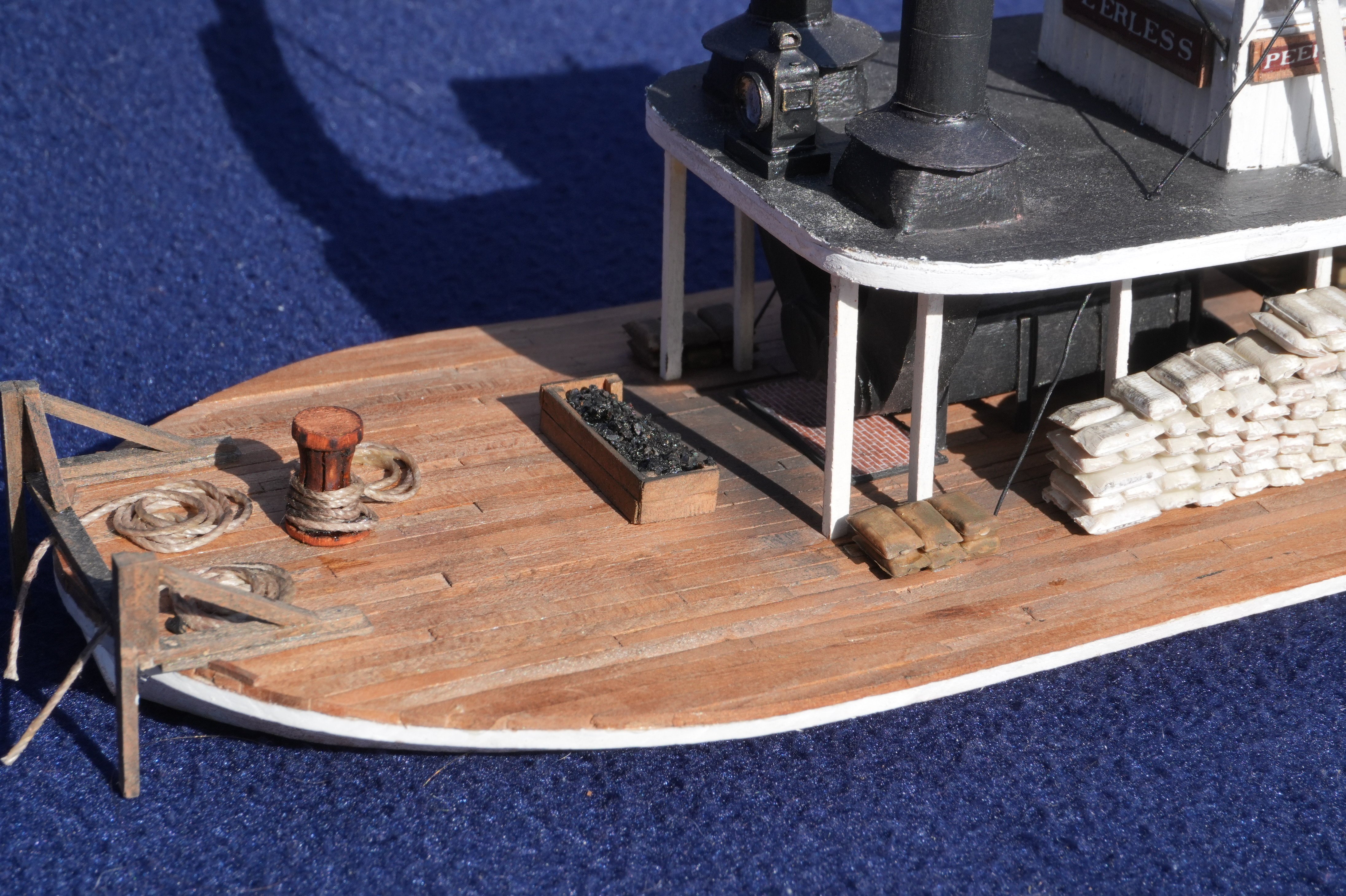
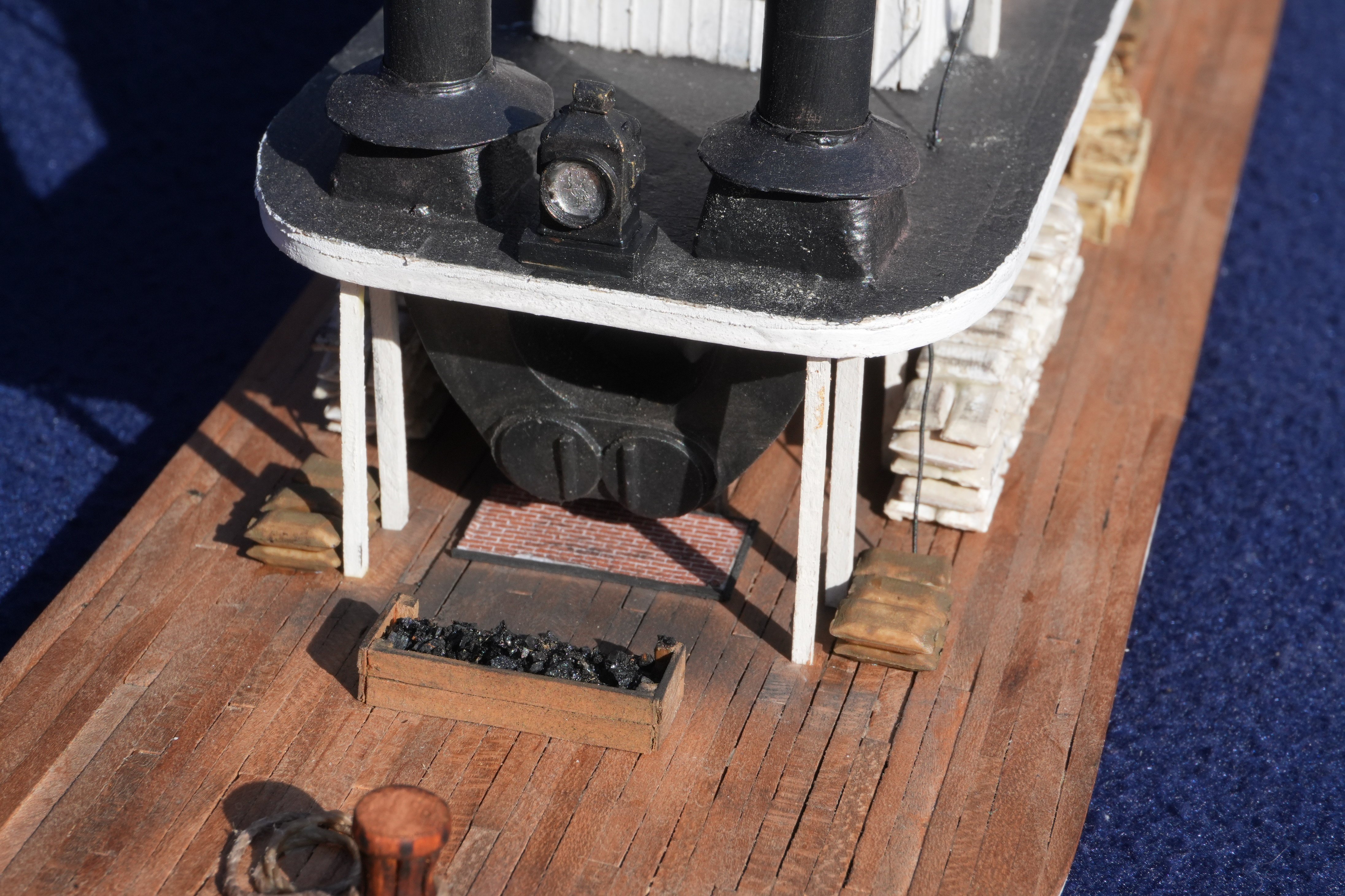
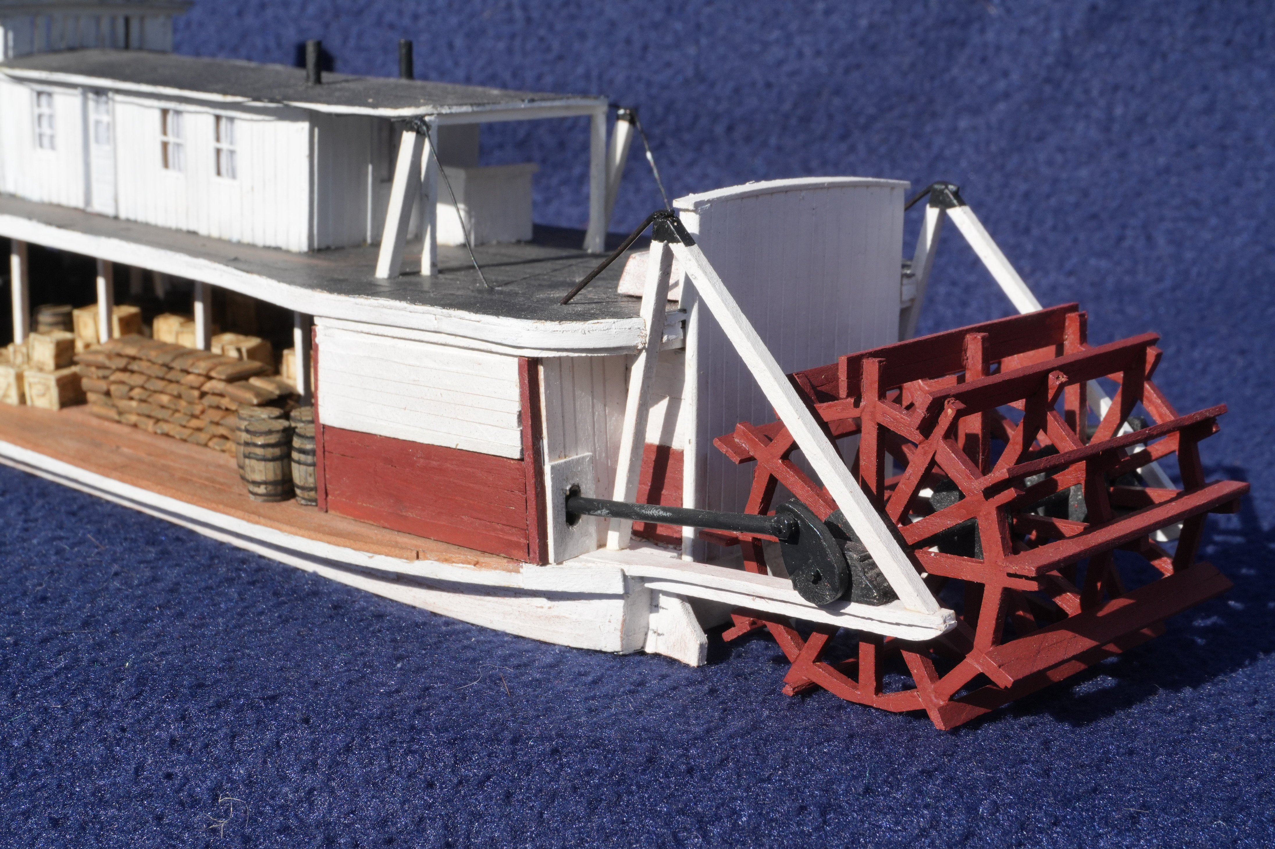
I have two fun updates to this log! One is to share some nice photos Mrs. Cathead took of the finished model, since I never really shared a full photo shoot of this build. The other is to announce that I've started a build log in the non-ships section of MSW for the model railroad project that will be Peerless' future home. This will be a major project for me over the next few years, so if you're interested in how it develops, come check it out. It'll feature my typical mix of sharing lots of local history and geography that influence the modeling work. Here's a teaser:


- 392 replies
-
- 17
-