Cathead
-
Posts
3,558 -
Joined
-
Last visited
Content Type
Profiles
Forums
Gallery
Events
Everything posted by Cathead
-
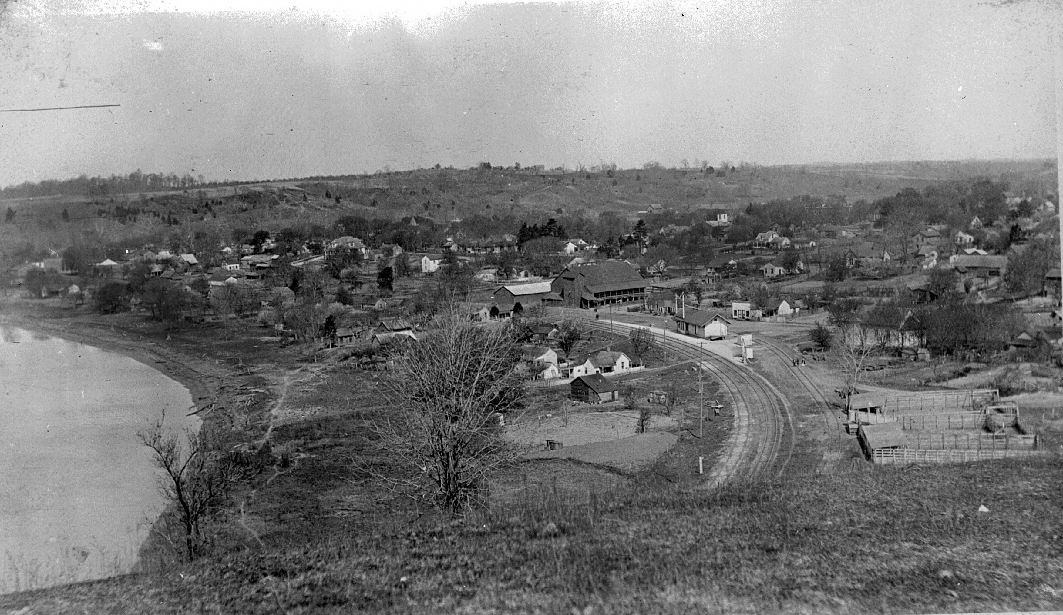
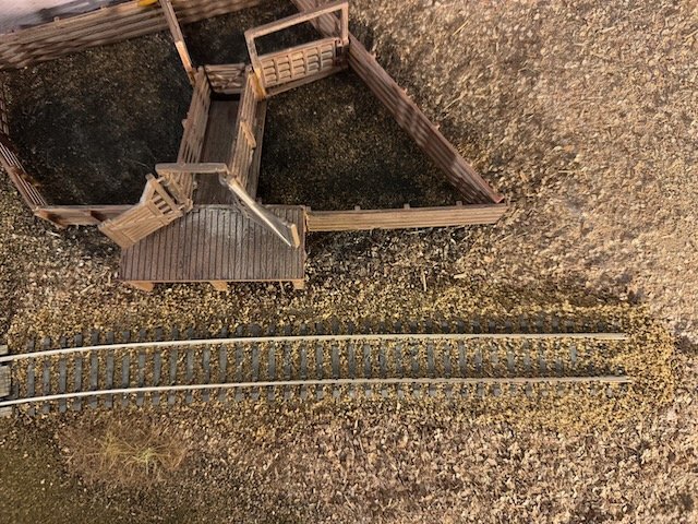
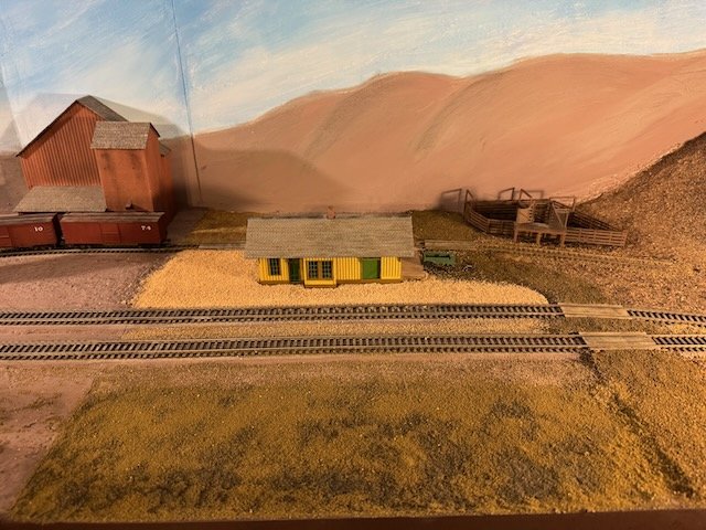
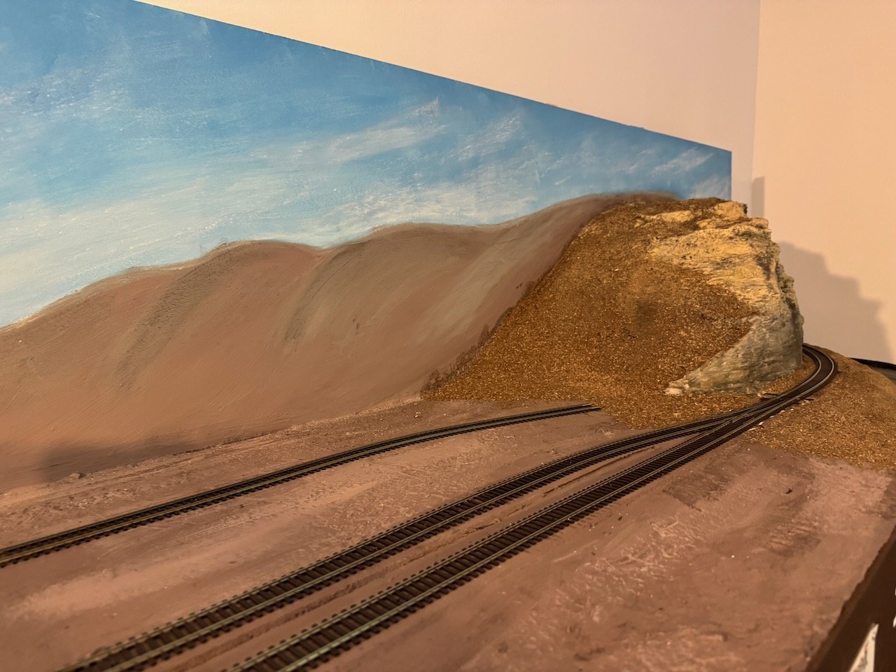
 Apologies for ghosting this log. Summer has continued to push us hard, with relatively little persona time. I do have two updates to write up, the shorter of which I'll do here, the longer of which I'll need more time for. I've moved forward with a bit more scenery work, mostly laying down base layers in the eastern part of town. Here's the current status: This is trying to replicate the pattern clearly seen in historic photos, of the depot area having a much lighter layer of ground cover (some form of sand/gravel) than the rest of the area. The foreground area will become a rough farm field; much of the area south of the tracks was functionally in the river's floodplain and had small farm plots on it. You can also see that I've filled in the road east of the depot and added a rough version of the stock pens along the spur behind the depot. Here's a photo of this area in the early 1900s. A couple closeups: here are some of the grade crossings, laser-cut wood castings that I weathered. And here's the stockyard part of the spur. Both the road and the spur's ballast are finished with sand from my local stream, sifted to a grain size I want. The stockyard is a cheap plastic modular kit; down the road I'll want to rebuild this from scratch using wood, but I had this sitting around, and adapted it to fill the space for now. At some point I'll use an airbrush to do some weathering on it. This all continues to look like Montana until I get more vegetation on it, but that's down the road yet. But at least I'm slowly moving forward with filling in the blank surfaces with something at least resembling scenery. Thanks for sticking with me on this! Look for a longer post at some point on my first test runs of an operating scheme for this town.
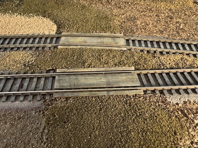

- 307 replies
-
- 15
-

-
Yes, nicely done. The slight angle there adds a lot of distinctive visual interest and you captured it well.
-
I should have added that the hogging problem was exacerbated by most riverboat hulls being built quite lightly, very different from your typical maritime wooden hull. A classic ocean-going hull was built super-strong, of heavy oak with very dense framing and lots of cross-bracing. These hulls were essentially rigid and didn't need additional trussing beyond the hull itself. But that's because they were deep-water vessels. Classic North American riverboats operated on shallow rivers and in an economic context that required them to be cheaply built, including that fact that their service lives were far shorter than that of a typical maritime vessel. So their framing was much farther apart and built of smaller timbers, their hull sheathing was light and thin, and they couldn't afford much cross-bracing without making the draft too deep. Plus, their hulls had to be flexible because they were highly prone to hitting bottom, where a rigid hull would break. So all of this meant the hulls were lightweight and needed the extra trussing of hog chain systems to keep them in line. Keith's vessel is operating on a reservoir but clearly derives its lines and design from classic North American riverboat design, with a shallow blocky hull made of wood that would require trussing to remain stable.
- 457 replies
-
- 7
-
-

-
- sternwheeler
- Hard Coal Navy
- (and 1 more)
-
Yes, in square(ish) hulled riverboats, hogging is defined by the bow and stern sagging relative to the center. That's why it became called hogging, because it resembled the arched back of a hog in an era when everyone knew what a hog looked like. It's less an issue of hull shape than of uneven loading on the hull. This was accentuated in traditional sternwheelers by having the heavy wheel hanging off the far end of the stern while the boilers and engines were up near the forward end. So these vessels needed a robust set of hog chains (actually iron rods despite the name) running longitudinally. In sidewheelers it became especially necessary to use transverse hog chains because the heavy sidewheels hanging off the side would otherwise crack the hull down the middle. Hog chains were an absolutely necessary and extremely distinctive feature of standard North American riverboats until steel hulls came along. In a perfectly rectangular and evenly loaded barge, you wouldn't need hog chains, but weight wasn't distributed evenly in powered riverboats. Early railroad cars had the opposite situation, supported at the ends (by the trucks) and peak loading in the center. But the engineering solution was pretty much the same, because either way trusses help distribute loading across a span. Keith's vessel is smaller than traditional riverboats, and also has a lighter wheel given newer metal technology, while the machinery is more amidships than on a "typical" vessel, but presumably the principle remains. Any wooden hull is subject to hogging and the weight distribution on his vessel is still uneven. And I agree that his photo shows a basic version of a longitudinal hog chain.
- 457 replies
-
- 7
-
-
-
- sternwheeler
- Hard Coal Navy
- (and 1 more)
-
The city is interested in keeping the Arabia museum, just not at the current site. Also, next time you plan a trip to KC, let me know, because I can think of a ton of interesting things in the city and area for people to do! But all this would take over CaptainMac's thread too much so I'm not going to dive into it. And yes, their other vessel is a much earlier one (think 1830s) and would be amazing, but they need space first.
-
Nice collection of books! If you're considering a trip to see the Arabia, don't wait too long, as its future is uncertain at the moment. The museum's lease in Kansas City runs out sometime next year and it's unclear what will happen next. The city seems to want that space for other uses (it's honestly not the best long-term use of that particular real estate), the museum wants a larger space so they can pursue another excavation, and several other cities have expressed interest. But it's all very much up in the air, at least in terms of what's been said publicly. It seems likely the museum will move, whether to a different location in KC or to an other setting, and that means a significant period where its collections won't be visitable. Given your interests and collection, another book you'd very much enjoy is an old Time Life book called The Rivermen, all about the history of the Missouri River. It's a classy volume in the tradition of how such books used to be made before the internet dumbed everything down, and I bet you can find a copy online or even through interlibrary loan.
-
What a great set of news and photos to catch up on a Friday evening!
- 457 replies
-
- 4
-
-
-
- sternwheeler
- Hard Coal Navy
- (and 1 more)
-
You forgot the third, a certain degree of certifiable insanity. If I tried this all I'd end up with was a bunch of pennies with stuff glued to them such that they wouldn't even go through a bank's counting machine!
- 457 replies
-
- 6
-

-
- sternwheeler
- Hard Coal Navy
- (and 1 more)
-
Turn "Live" Off on an iPhone Camera
Cathead replied to palmerit's topic in Photographing your work. How to do this.
If you're exporting photos directly from the phone, it's easy to turn the live status on/off within the Photos app. There's a menu on the upper left of any live photo that lets you flip between live/loop/bounce/off, etc. Then it will export as a jpeg rather than video. It can be done within the computer version of the Photos app, too, but it's more complicated; you have to hit Edit (like you're going to crop or color balance it) and there's a menu in there to change the live photo setting. Once you set it to off, it exports like a normal photo. Neither of these deals with the problem that you can't choose which frame of the video to export. Ironically, since in actual videos you can. The real answer is to just pay attention and turn the live feature off when taking model photos, just like you would adjust any other setting (like flash on/off). Personally I can't understand why people leave the live photo feature on all the time. It takes up a huge amount of space storing all your photos as short video clips. I turn it on for very specific needs when having motion actually helps enhance the effect (like a waterfall). But to each their own.- 1 reply
-
- 4
-
-
Thanks for sharing this sad news with us. My condolences to all who knew him. I concur with Kurt, please post any updates about installation at the museum for those of us in the region who might be able to come.
-
I partly have to decide sooner, since once I've placed trees in front of the backdrop I'm not easily going to be able to remove them again or get behind them to redo the backdrop. I agree, but I also relish the challenge and the distinctive look! Your photos look awesome. Yes, this is the general plan in most places. The most exposed seam will be where roads go directly into the backdrop and I have yet to decide if I'm going to try and have them blend into the distance or just go blank. The problem with a town scene in which most of the town is just behind the backdrop is that it feels all or nothing; if I paint on a receding road, there needs to be receding buildings, too, and I'm not sure I'm up for getting that right. Something that looks wrong is often worse than something just not being present, since the eye and mind will fill in missing detail but will notice wrong-looking detail. That's what I did...the bare bluffs receding on both the left and right sides use the same paint/pastel mix as the foreground plaster rocks. I'm pretty happy with how those transitions turned out; at the very least I don't think I can improve it. Another challenge in such backdrops is that viewers see them from so many different angles that there's no one "right" perspective. Viewed from one angle, a receding bluff line or creek can look great, and viewed from another angle, can be at an awkward angle. Very different from a true "flat" painting in which the perspective more or less stays the same no matter how it's viewed. For better and worse, I've mostly tried to orient the perspective from a trackside view, such that certain things look a bit "off" when viewed from a normal standing angle.
-
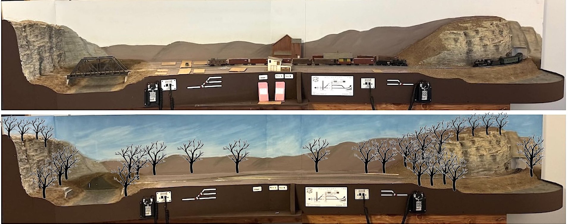
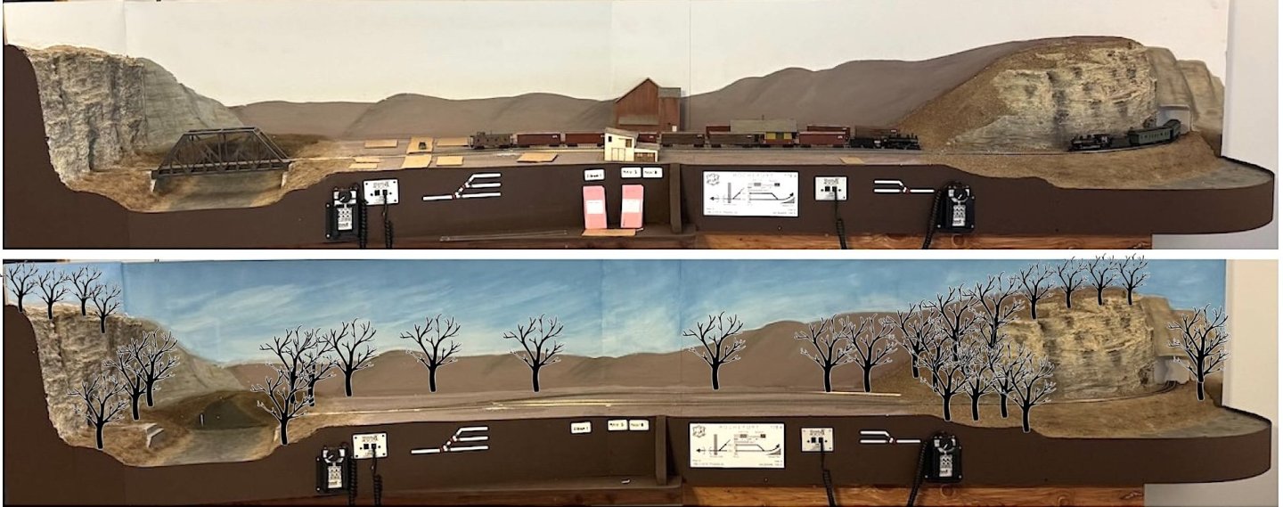
After posting that, I decided to do a little visual demonstration. It's easy to focus on the backdrop when it's the dominant thing you see without the foreground details in place. So I went back to the comparison photos I posted earlier, and added some basic tree silhouettes to give a better sense of how trees will break up the horizon and focus attention on the foreground. This is roughly the plan for major tree location: And this doesn't include the added effect of buildings, which granted will be no more than 1-2 stories except for the elevator, but will still further focus attention forward. What this suggests to me is that I shouldn't worry about most of the background and horizon, but that I might want to carefully draw in some suggestions of trees along the top of the left-hand bluff line receding away above Moniteau Creek, as there the foreground trees vanish abruptly once the bluff reaches the backdrop. Same for the bluffs on the far right. But that's (a) a much more narrow and doable space and (b) will only be needed in a handful of other places elsewhere on future backdrops. Thoughts?
-
Great question. I don't plan on sponge painting as that's usually best for simulating foliage, which wouldn't fit for this late fall leaf-off setting. I'm still trying to decide whether I want to try drawing on a blend of bare trees or just leaving it as a hazy background. The challenge I see is that adding that level of detail would be all or nothing; if I can't get it the way I like, I'm going to have to repaint the entire thing because I can't just blend it back in the way I can with the current hills. And perspective/distance would be hard; the details of the trees would have to change from foreground to background or it'd look ridiculous since the way I have the hills painted represents quite a bit of depth (from right behind the foreground to miles away). In other words, if the backdrop were "flat" and just needed to represent a line of trees right behind the foreground scene, it'd be easier to add more details. But I'm not sure if I can get the perspective right with slowly blending fainter and fainter tree details as the perspective retreats back. You could argue that sponging would work for giving the faraway hills some texture, but I'm not sure how to blend that into more detailed trees in the near-ground. Partly just my artistic limitations since I have no real painting experience. And this is also why I'm not sure it's worth trying to super-detail the backdrop. It stands out right now, but once the town buildings are filled in, and there's even a handful of bare trees breaking up and obscuring the horizon, I'm not sure the extra detail would really stand out enough to justify the work. I'm less worried about making any still photography look photo-realistic and more about creating a setting that feels real and immersive when you're operating trains in front of it. The other consideration is that the current scene isn't meant to stand alone, but to be part of a larger layout eventually. So whatever design/color/detail style I define for this scene, I'm going to want to extend reasonably consistently to all the other scenes. IF I take this project to its full extent, I'll need at least another 50' of backdrop in addition to the current 11'. So do I want to be drawing/painting on complex tree details for another 50+ feet down the road so all the scenes feel consistent? In other words, whatever I do here defines the "style guide" for the rest of the potential layout, which creates different considerations than if this was just a stand-alone diorama. All of which is why I'm leaning toward leaving well enough alone, but have not actually decided. It's possible I could paint a small test-case panel off-layout reasonably close to the current backdrop style and see if I can create a more detailed style that's effective and efficient. Oh man, what did I just talk myself into when I just spent this whole post talking myself out of doing more work!
-
Always good to see a build log come back to life!
-
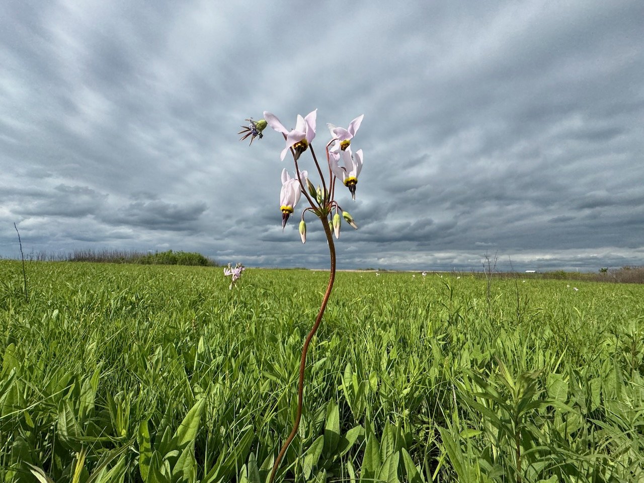
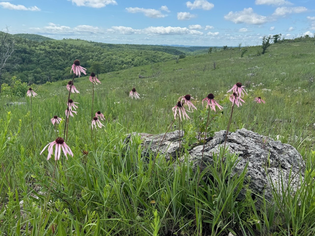
Thanks for all the feedback and advice! To be clear, I am familiar with the basics of photography and Mrs Cathead is a moderately skilled SLR operator. I just tend to use my iPhone on a day to day basis because frankly, it matches the SLR about 70% of the time and I personally don't enjoy using "real" cameras. I'm actually pretty good about adjusting phone settings to get good results when I want to (I do a lot of nature and landscape photography for both work and pleasure), and I tend to have a good eye for composition. I just don't always fuss with it when I'm doing basic model photography. Maybe (probably?) I should, but I don't. And for what it's worth, the nearest camera store is over 100 miles away! Here's a couple examples of phone photos I'm happy with. First one from a central Missouri prairie, second from a south Missouri glade. Neither has been altered in any way. I'll hopefully have another update this weekend.
-
LOL, you guys are way ahead of me. I'm just using an iPhone.
-
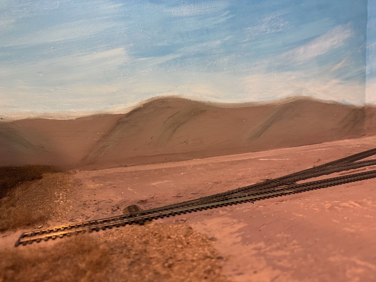
Yeah, I think it's the photo color balance. Here are a few closeup shots just to show what this looks like, partly since the camera "lies" from distance. These all have an odd, Mars-like red tint that demonstrates color balance oddities. These also show that, like many things in modeling, a sufficiently close look can ruin the illusion (the clouds look more like paint here) but I'm still pleased with the result. I also went through and touched up both the clouds, and the horizon interface with the hills, using pastels to soften some areas and blend sharp boundaries. I don't think you can tell the difference in the photo below but it looks better to me in person. I brightened this photo; the version below looks a little closer to the in-person view, and also closer to what it might look like when I get the overhead lighting installed. Thanks, Keith! And to all of you for the likes, comments, and interest.

.jpeg.7d464e4407dc6f4b2f1f88eec9d1b7b9.jpeg)
- 307 replies
-
- 11
-
-
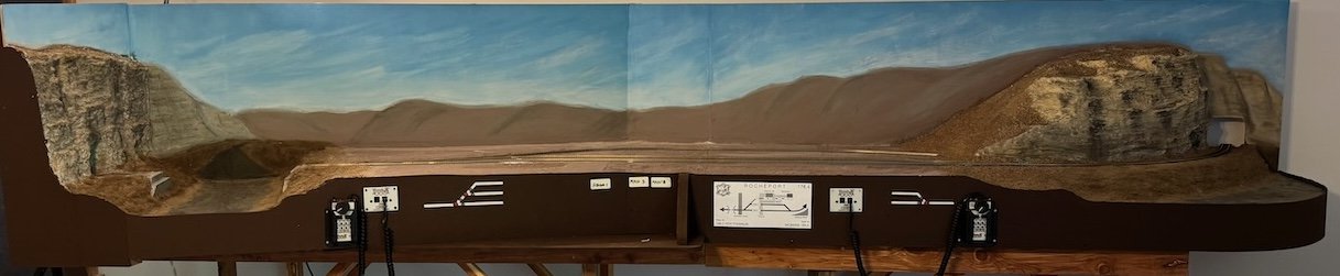
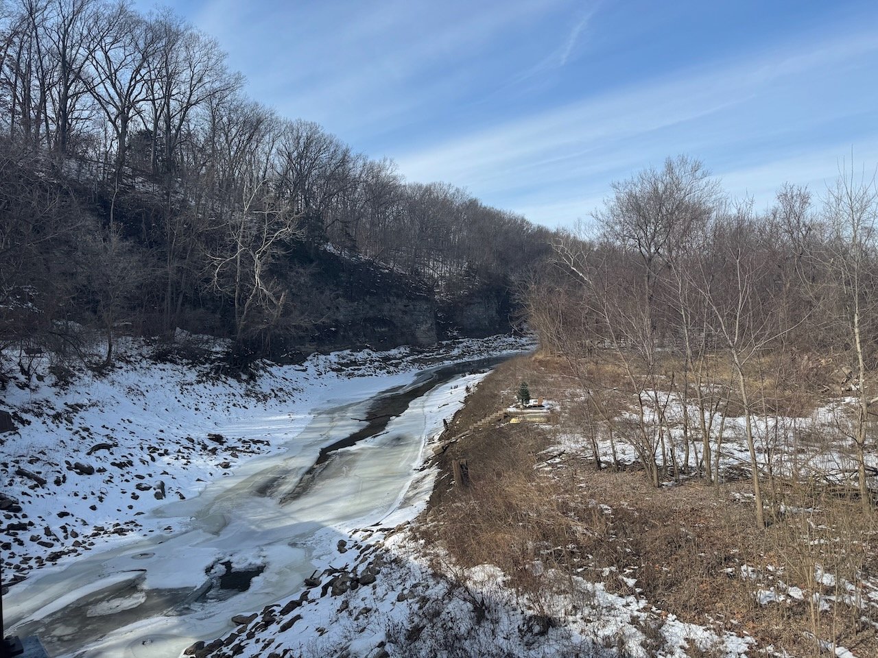
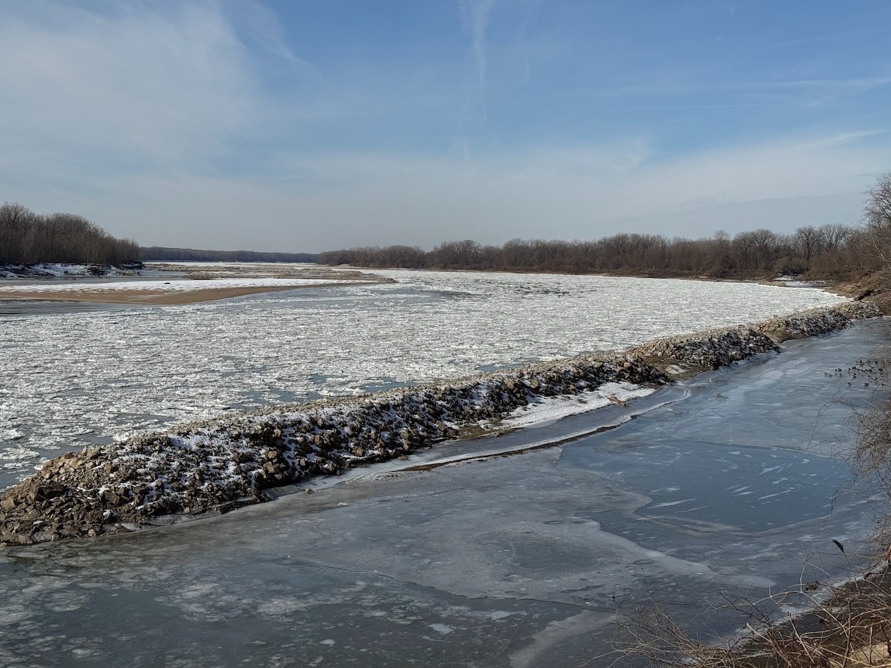
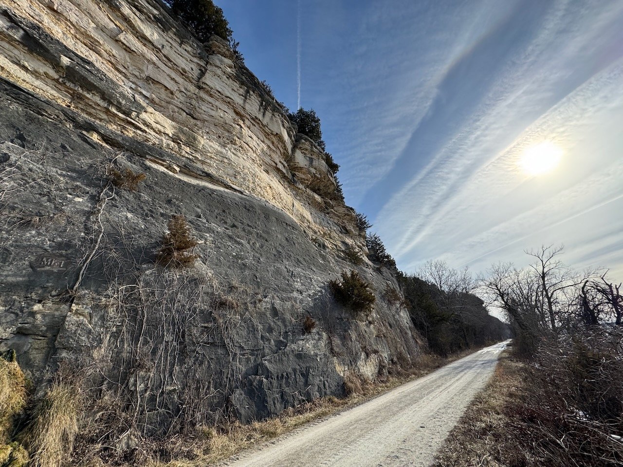
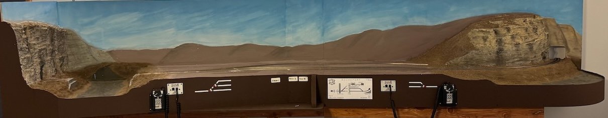
Here's a quick update on an upgrade. I finally made time to properly finish the backdrop. Although I did kind of like the bland threatening overcast look of the base sky color, I had planned on a different look. Some of my favorite Missouri winter days are those with clear skies but a haze of high clouds portending a change in the weather, like these reference photos from the Rocheport area in January: And here's a before-and-after pair going from the background to the finished sky: Thoughts? I'm trying to decide (a) how well it matches the reference photos and (b) whether I do in fact like a more overcast, threatening look. You'll note that I was historically accurate and did not attempt to recreate contrails... EDIT: Just realized I didn't describe HOW I did this. It's a technique pretty common for model railroaders; for example searching YouTube for something like "paint model railroad backdrop" will get lots of results. Basically I laid down a fresh roller layer of blue paint, then started brushing white in from the bottom, blending the wet paint upward to go from hazy near the horizon to brighter blue higher up. Then I started using brush strokes to develop the elongated hazy cirrus-like clouds, going back over everything with the roller now and then to blend things in. I actually ended up nearly done and then started over, because my first version was too blue and not hazy/cloudy enough. I also made things hard for myself by being over-perfectionist and trying to keep touching things up as the paint got too dry, which makes blending harder. One other thing I did that you shouldn't do, is paint the foreground hills before the background sky. It's a pain to try and blend sky into pre-existing hills; much easier to start from the back and work forward. But that's not what I did and it just made the job a bit harder. You can't see it from the distance of these photos, but I need to go back through and use pastels to blend in the horizon/hill interface a bit. No excuse; I just got ahead of myself in being excited about scenery and didn't take the time to do the sky first. Oh well. I think it came out pretty well.
.jpeg.bed2a9378df2699d53e4db071c867e16.jpeg)
- 307 replies
-
- 14
-
-

-
I mean, I'm regularly floored by your work, so I might as well floor along!
- 457 replies
-
- 8
-
-
-
- sternwheeler
- Hard Coal Navy
- (and 1 more)
-
Great start, sorry I missed this when you launched. As one of the resident steamboat aficionados here (see my signature links), you've made a great choice of kit and subject and I'm super excited to see how you progress. If it's of interesting, @kurtvd19 has a really great set of extra instructions and context that can help you get even more out of this model. Hopefully mentioning him here will summon him to make contact with you. Welcome to MSW!
-
For what it's worth, if my memory and understanding are correct, there were hand pumps on even larger riverboats like Arabia for just this sort of scenario (priming boilers when the steam was down). Granted, that was in the mid-1800s, so by your era any sensible crew may have told the idea of a hand pump to take a long walk off a short barge and installed a gas pump like you're suggesting.
- 457 replies
-
- 4
-
-
-
- sternwheeler
- Hard Coal Navy
- (and 1 more)
-
I started hearing the theme from Jaws as soon as I saw that. Very cool idea to add that. To be honest, I thought it was a loudspeaker when I saw it and wondered why you had a tornado siren on there. It's nicely done, it's just a lot bigger than the one in the original photo. So I'd agree with you on redoing that one. Everything else looks great!
- 457 replies
-
- 6
-
-
-
- sternwheeler
- Hard Coal Navy
- (and 1 more)
-
Man, if you don't like that effect and think you can do even better, I'll just leave my jaw on the floor until you try again. It'll save a new bruise.
-
Well sure, you'd think so, but the reason I got involved in this particular theme was that one of the earlier kit images you showed had what sure looked like the wrong Cyrillic letter, or at the very least a really poor rendition of one, so I was just celebrating that the part you showed this time was right.