Cathead
-
Posts
3,532 -
Joined
-
Last visited
Content Type
Profiles
Forums
Gallery
Events
Everything posted by Cathead
-
 Keith, those little details look great. So glad you've found the groove again. I know how it feels to try and get one's head back in a project.
- 732 replies
-
- 4
-

-

-
- Lula
- sternwheeler
- (and 1 more)
-
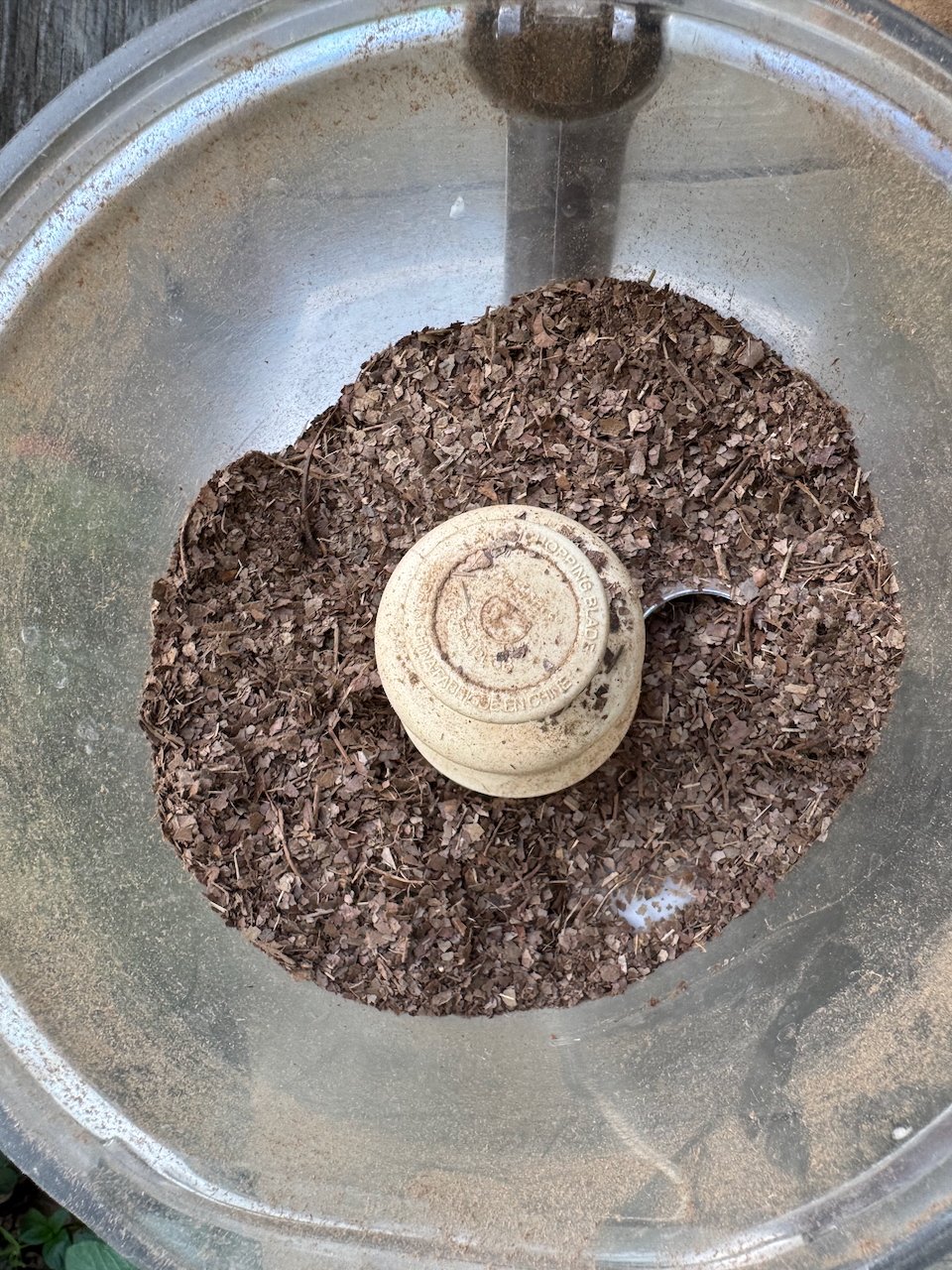
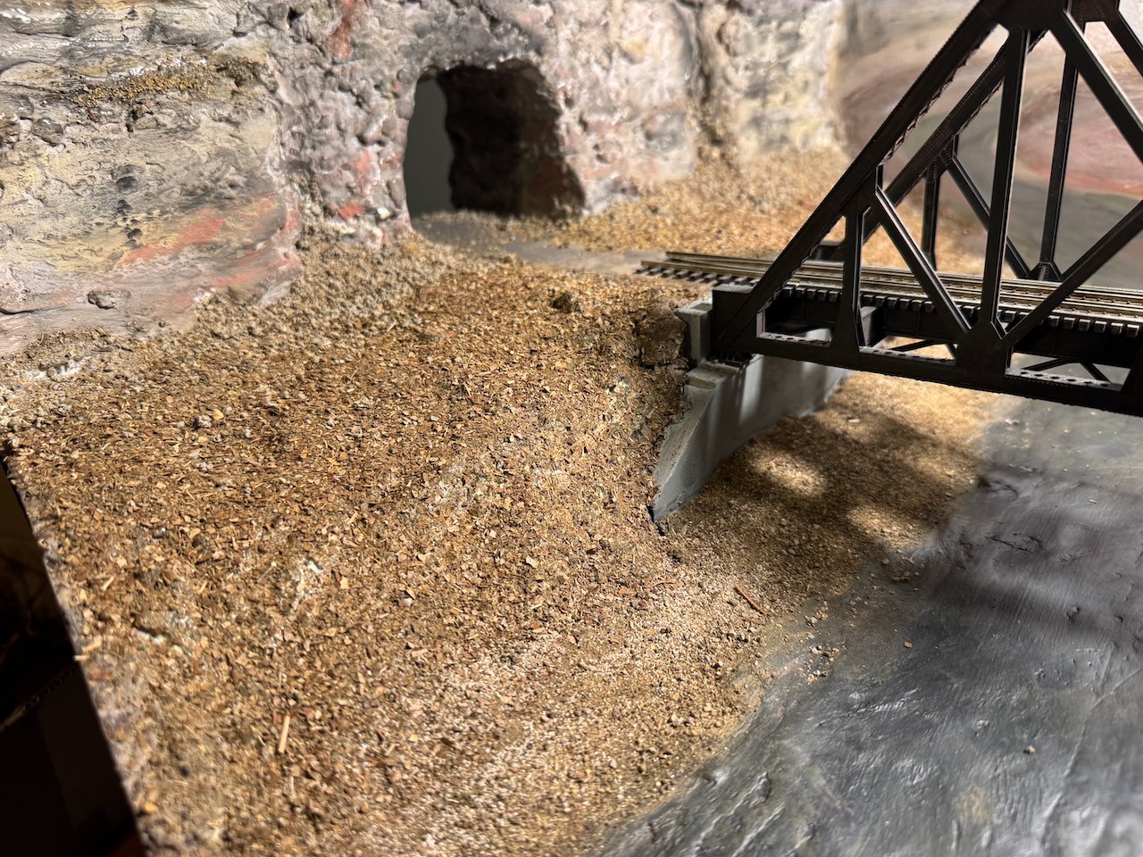
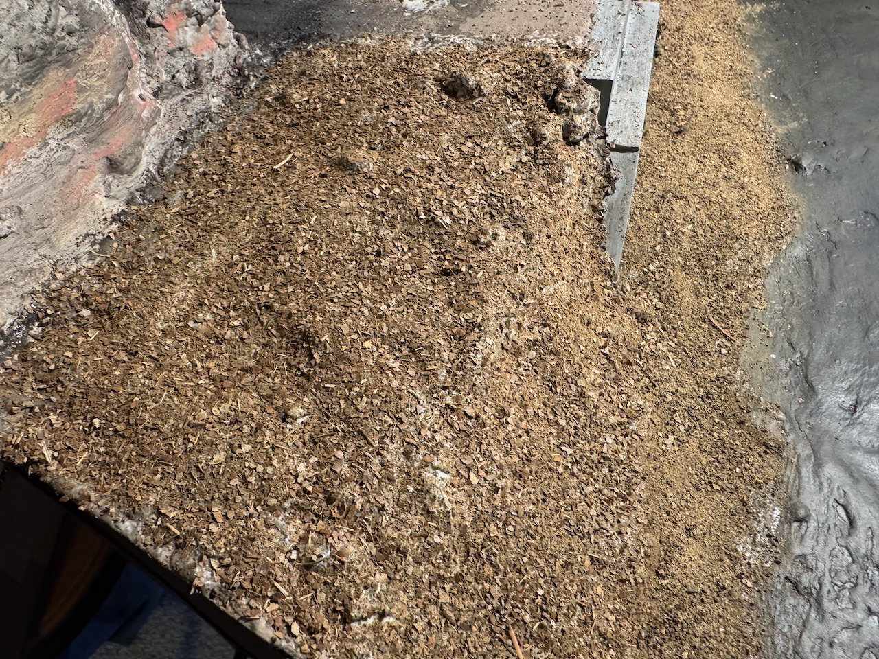
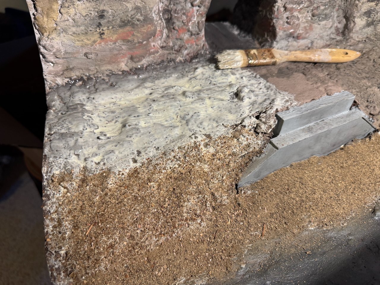
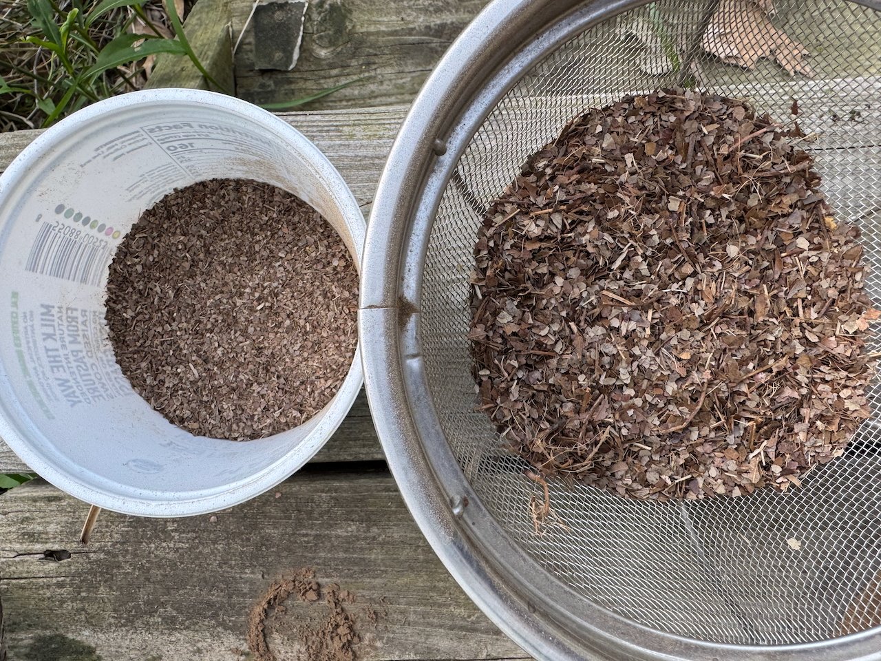
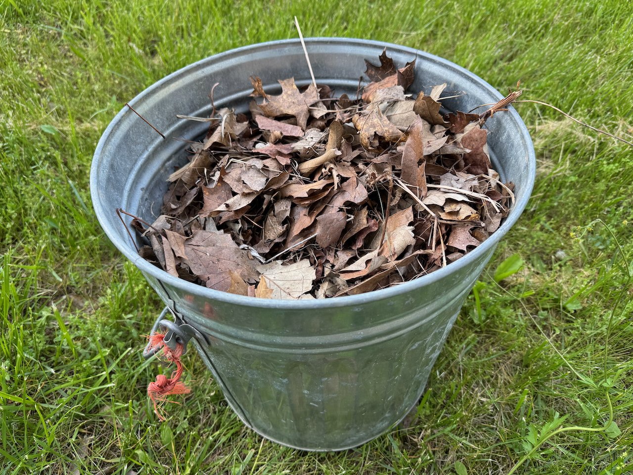
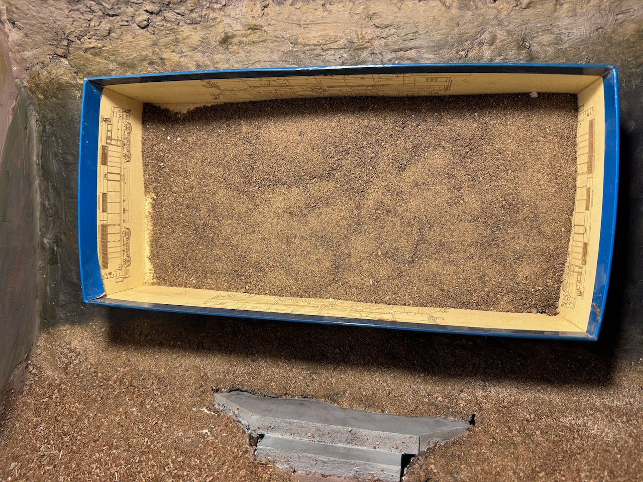
Got a little more scenery work done this weekend. It was time to start adding texture to the riverbanks and ground surface, so everything doesn't look like smooth plaster. As I've said before, one of the reasons I'm setting this project in late fall / early winter is that it lets me produce a lot of scenery material from natural sources rather than buying lots of plastic/fake stuff. It's hard to maintain a natural green color, especially one that looks real, but natural brown tones are a lot easier to come by. I started with a bin of dried leaves I'd set aside, running these through an old blender in batches to pulverize them. Some bits never shred all the way, so I used a sieve to select for the smaller sizes. In my head, I call this blend "fish food" because it looks an awful lot like the flakes used to feed aquarium fish. Similarly, I collected a batch of fine sand from the creek on my property, which has the same geologic setting as the headwaters of the creek depicted here. A similar sifting process gave me a blend of scale "gravel". In both cases, using natural materials gives a spectrum of subtle natural color variations that I find a lot more visually complex and realistic than purchased scenic materials with a limited range of tones. To apply this on the landscape, I brushed full-strength glue over the painted plaster, then sifted/sprinkled material onto it. I ran a band of nearly pure "gravel" along the creek, then slowly reduced its quantity as I worked up the bank, increasing the proportion of leafy material. By the upper floodplain surface, it's almost all leaf material. To my eye, this gives a really natural looking transition out of the creek and up into an area that will have a lot more trees and vegetation. All of this material is coarser than true scale, but I find that it helps the eye "see" the right texture. In my opinion, true scale material would be so fine it would "look" too smooth. A strong modeling belief I hold is that it's just as important that a scene "look" or "feel" right than that it "be" right. And to my eye, this creates a feel that the eye connects to real landscape textures even if it's technically out of scale. The random chaos of the particle shapes, in both the leaves and the sifted sand, also helps create a more natural-looking texture than purchased material that tends to be more uniform. At least that's my opinion. And philosphically, I just love that these scenic textures are all-natural and sourced from a landscape near the actual real-life scene. Here are a couple broader shots showing the finished effect on this bank. I also added some coarser rock material along the base of the bluff to blend the transition from vertical to horizontal, and to produce the effect of fallen rocks that's very much there in real life. I'm finding that the finished textures looks different in these photos than it does in person, though, and my phone isn't handling the depth of scene here well. But that gives the idea. I haven't run this by my in-house landscape expert, though, so we'll see what she thinks. It can be adjusted if needs be. Once we're happy with it, I can start working on trees and other vegetation that will further tie the scene together. Thanks so much for following, liking, commenting, and being a part of this slow-moving project!

- 264 replies
-
- 14
-
-

-
I would have written much the same as Glen had he not beaten me to it. It's startling how good a completed model looks when presented as a whole, regardless of whatever smaller issues exist.
-
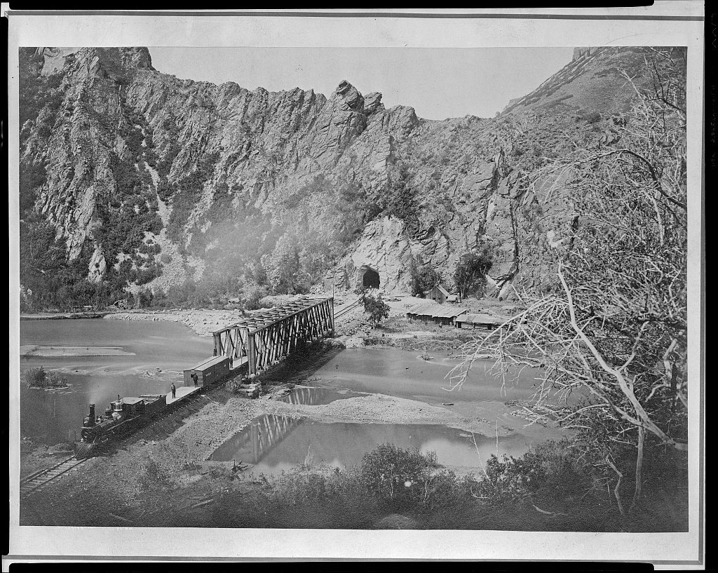
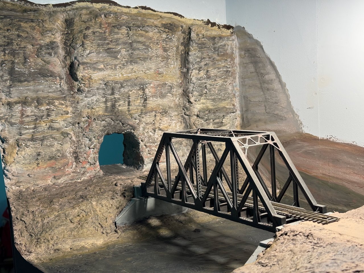
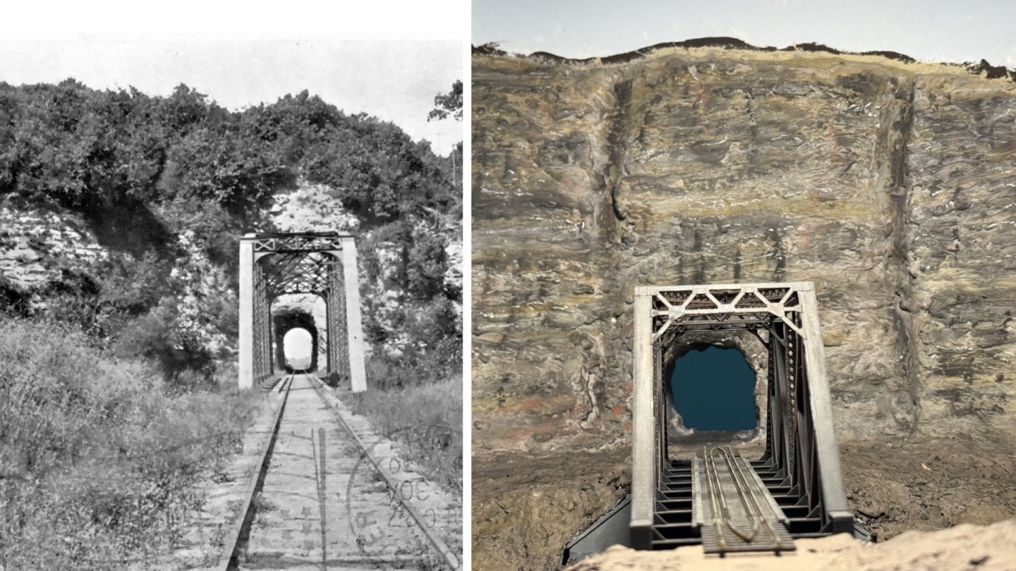
Thanks, Gary! The current appearance of this scene, and particularly this angle, has been nagging at me, reminding of some famous railroad scene or photograph. I finally figured out what it was: this view of Weber Canyon on the original Union Pacific transcontinental route (photo from Library of Congress). Sheer rock wall, truss bridge over river, leading directly into tunnel. The similarity will start to fade once my scene starts taking on more vegetation, but the comparison amused me.
-
I'm not an engine room expert but your explanations seem solid. You're giving @FriedClams a run for his money in terms of precise, gorgeous, detailed workboat builds.
-
No worries, I appreciate you taking the time to think about the project and make suggestions!
-
Oh, no, rocks are regularly dropping off that face and the other bluff lines along the route. I've got photos of dinner-plate-sized rocks that spalled off and got caught in the vines that often lace these bluffs, and end up dangling in midair like cargo in a ship's loading net. There's regularly little piles of debris at the base of the bluffs, and I've moved debris off the trail more than once at the tunnel mouth. It's mostly very small pieces, but it's definitely an actively weathering surface. I can only assume the railroad regularly checked the portal area for debris on the tracks, since they never stabilized it further. To give a quick written recap of the geology at the portal, most of the bluff line there is Mississippian limestone laced with chert beds. But paleo-karst is quite common in these rocks; there are many places where old caves developed in the bedrock and then either collapsed and filled in with Pennsylvanian sands. All along this route you can find unusual protruding outcrops of hard sandstone that are essentially filled-sink structures, more erosion-resistant than the surrounding limestone, so remaining behind as filled molds when the limestone dissolves. As it turns out, this portal is drilled right into one of those collapse structures; 10 m to either side and it's solid limestone, but right where they put the bore, it's a complex massive breccia of chert and other rock fragments that collapsed into the paleokarst. This extends well into the tunnel, pretty much as far as to the point where they started the brick/stone lining out to the western end. Like the other filled-sink structures, it seems to be relatively solid and well-cemented, and most of the debris I see coming down off the bluff is from the limestone spalling off higher up, not actually chunks from the breccia. This observation fits the fact that the railroad never bothered to line this part of the tunnel, so seems to have realized that the filled-sink breccia is in fact quite stable, despite looking like it shouldn't be.
-
I would agree, except that the tunnel isn't a dead-end, but will continue through to a new module. See track plan in post #61 and look at the right side of the area labeled Rocheport (viewing angle is from the top down). The other portal will be on the next module in that direction. What's beautiful here is that this tunnel changes partway through; it's bare rock on this (east) side but lined with brick and stone on the other (west) side. So when I build the next module, I'll build that half of the tunnel as brick and stone, then when they butt together the joint will naturally look right because there really is a transition in the middle of the tunnel. See the video part 2 linked above to really appreciate this. Here's a sneak preview of the western portal: Good questions! There is no faulting, though there are a handful of major vertical joints, which are already simulated. The ones on the model are a little more uniform top-to-bottom than the real ones, but I think they're close enough. Smaller "structures" you may be seeing are probably fracture planes where rock is locally spalling off the bluff face. I may experiment with using a dark pencil to draw in a few other fractures, but overall there isn't much in the way of vertical structural features crossing bedding planes. I don't intend to use any fixative on these surfaces, as they won't be touched or handled. I apply most of my pastels with fingers and find that skin oil does a remarkable job of binding pastels to most surfaces. I've never used fixatives even on my ship models; I'd only do so for things like actual railroad cars that will be routinely handled.
-
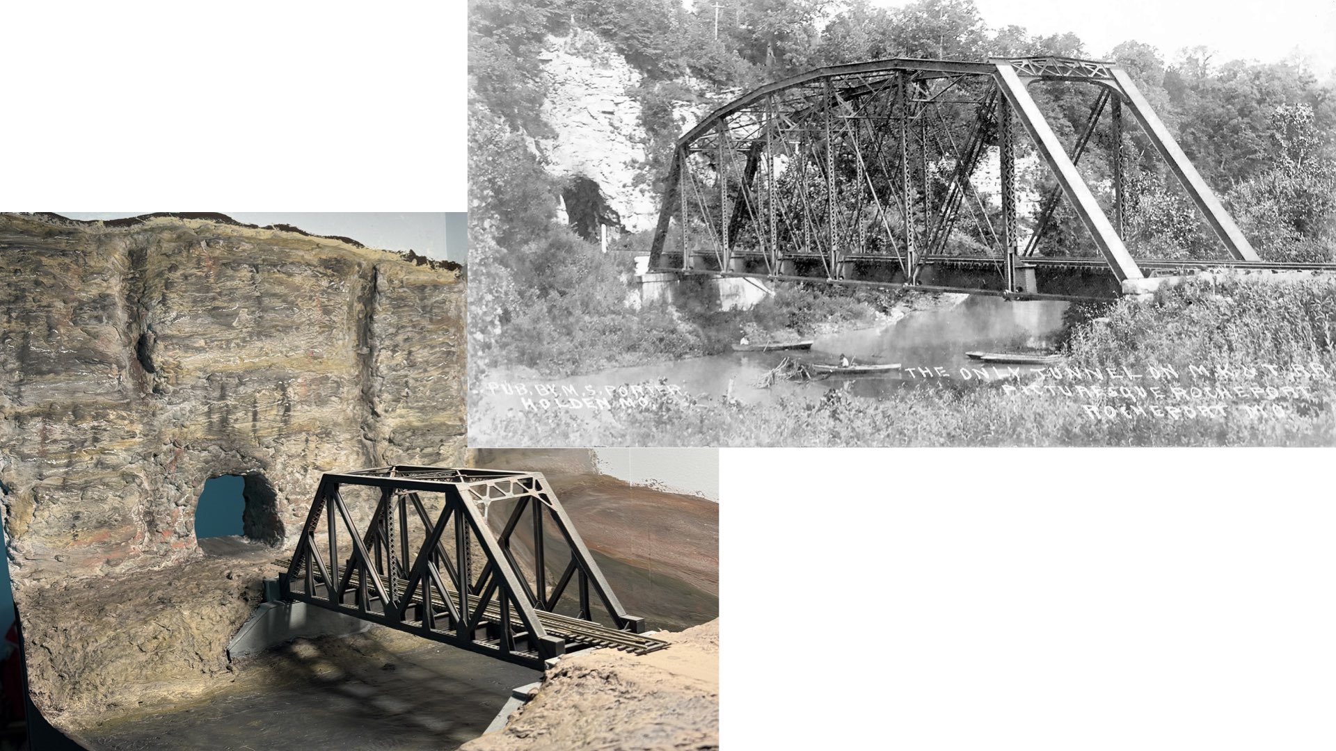
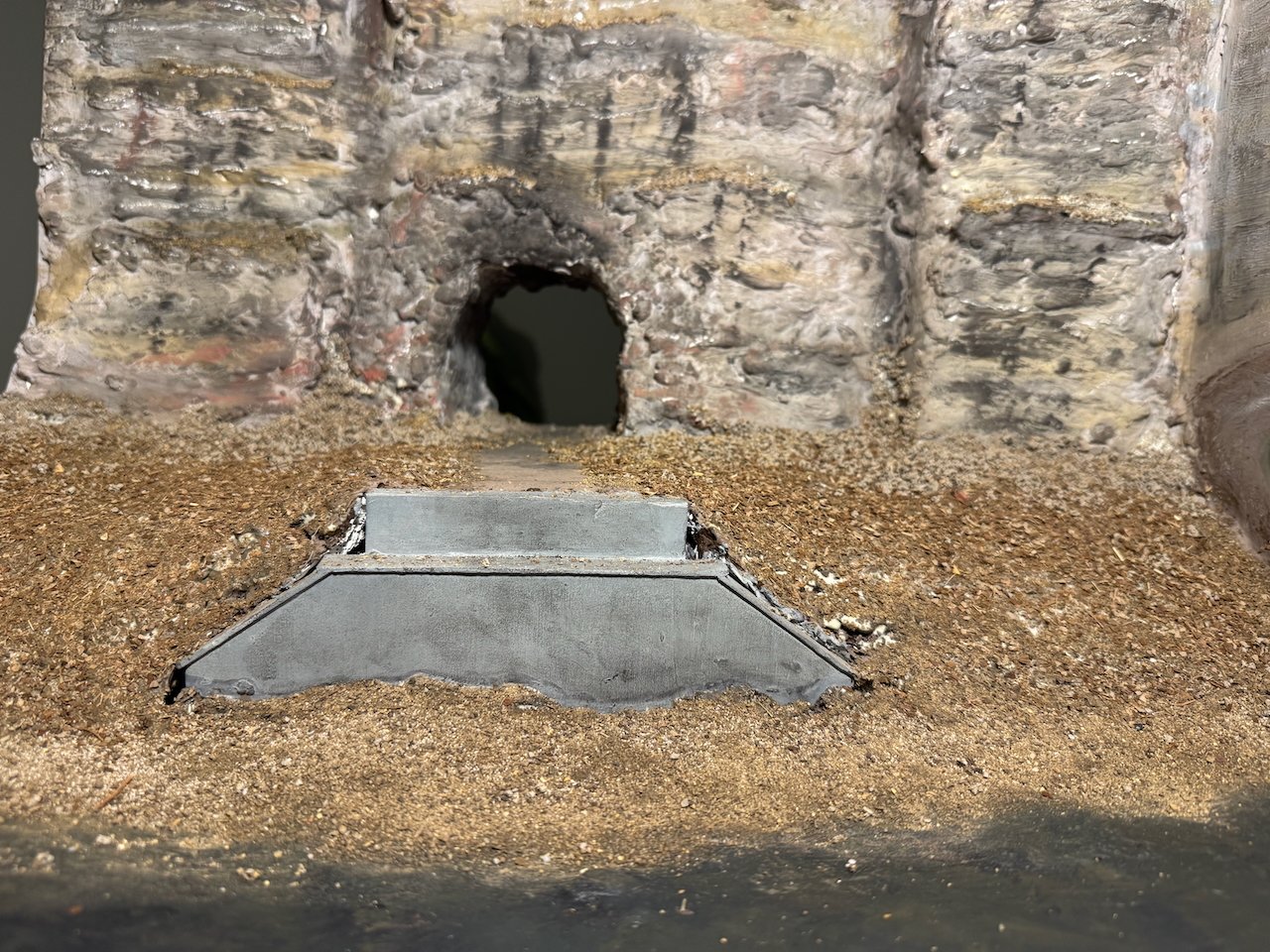
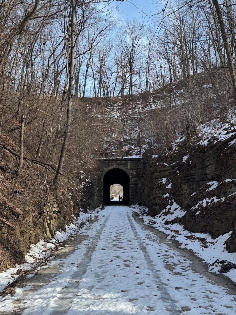
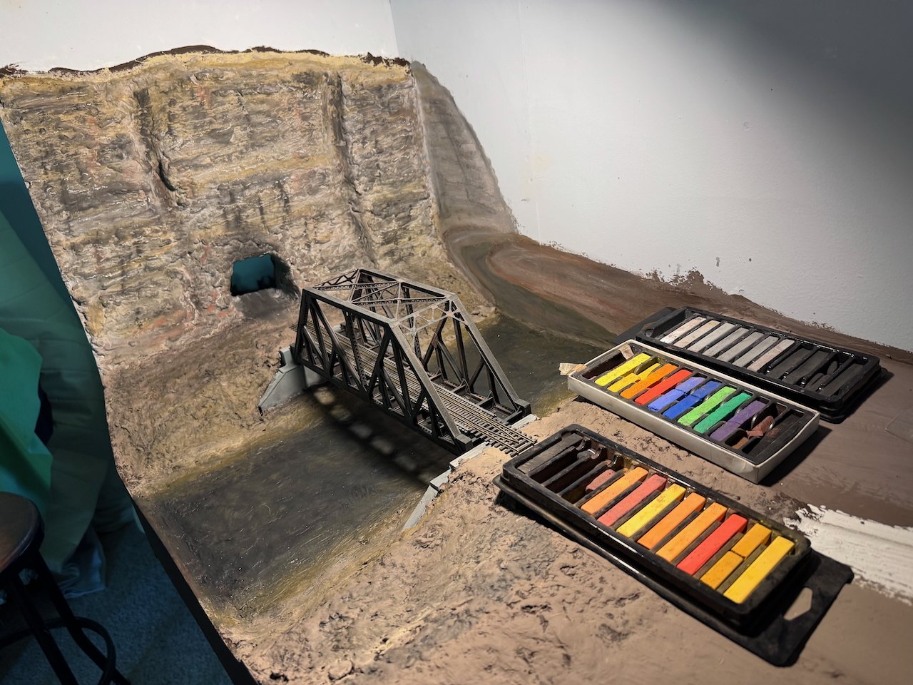
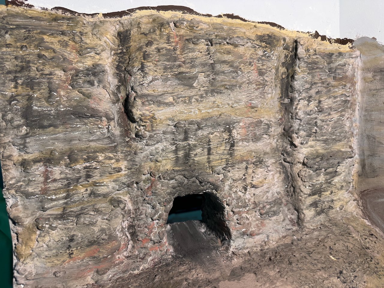
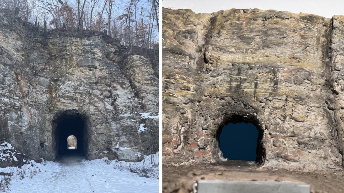
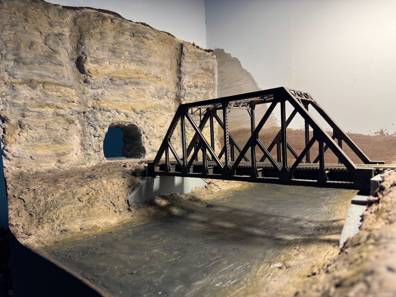
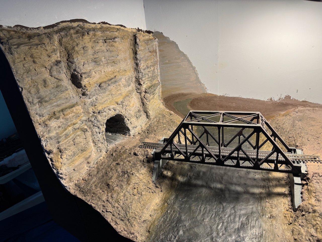
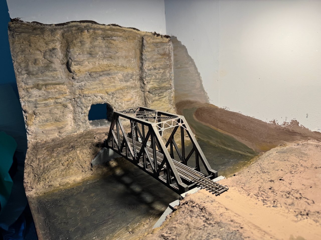
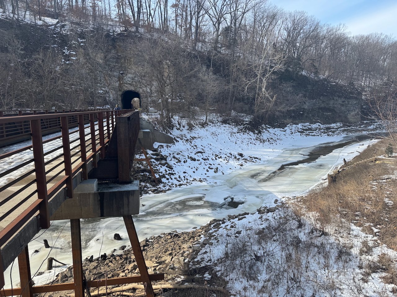
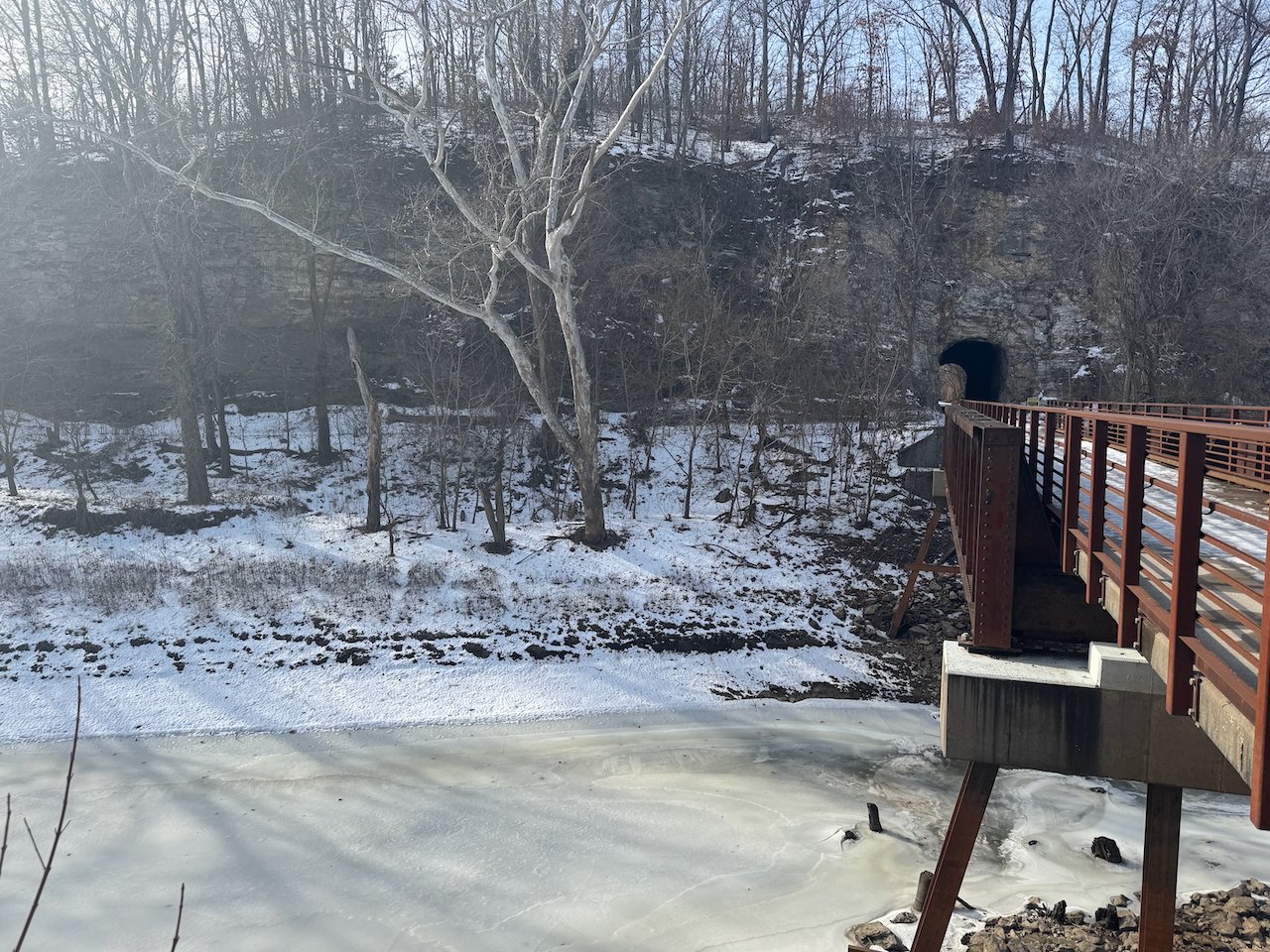
I spent some time this morning adding color & texture to the rocks using artist's pastels. I use these all the time for weathering models, and they're really effective at finishing scenic settings as well. They don't drip, and can be rubbed in with fingers or brushes (old toothbrushes work really well). Their powdered texture adds a "softness" to rock faces that paints don't, which helps them feel more realistic. I also touched up the backdrop with these, which again softens the painted took and allows more subtle textures than paints do. Here's a broad view: Here's a closeup of the rock face. The pastels let me add mineral staining as well as streaks of white that simulate the various layers of white-grey chert laced within the limestone beds. I also added smoke stains above the tunnel. And for further comparison, I made these three sets of photos with similar perspectives. First, modern portal and model equivalent. This shows one thing I didn't get right; it's becoming clear to me that my tunnel shape is a little too squat; it should be taller for its width. Can't change it now and it'll still clear trains fine. Second, historic photo directly down the tracks and model equivalent: Third, historic photo from side and model equivalent. I've mentioned this before, but I know the bridge doesn't quite match. For now I'm using a simple kit; someday I'd be happy to build a closer-matching bridge from scratch but it's not my priority. I think I'm happy with the coloration, so the next step is to move on to things like adding ground-surface texture, water, and eventually trees (so it stops looking like Wyoming). Thanks for following along!

- 264 replies
-
- 16
-
-
-
Made some progress on base-layer scenery painting this week, taking a few minutes over multiple nights to slowly build up layers of color. Right now, without any vegetation, it looks like somewhere in Utah or Wyoming. But that'll change. I also took a first stab at some basic backdrop painting, just trying to add a hint of hills/river extending into the background. This isn't meant to be photo-realistic, just enough to let the eye realize that it's not all backdrop sky back there. Also, the creek has been painted but I haven't added the model "water" yet, so it's just a dry surface. There will be multiple layers of "water" resin added, building up a sense of depth and a smooth surface. I also plan to tint the "water" some, as the real creek here tends to be pretty muddy, and this also helps fade the water into the painted "depth". Most of the ground surface will be covered in various scenic materials to add texture, so the painting there doesn't need to stand on its own, but just provide an underlying foundation. I'm not done with either the backdrop or the main bluff. Final touches on the bluff will include some more dark washes to bring out texture and cracks, and some vertical washes to simulate mineral streaking. The backdrop needs more texture, and the outer edges will be sharped up once I paint the sky (which I haven't done yet at all; that's just white primer). But I thought I'd share progress and get feedback. You can at least get a sense of where I'm going with this. Oh, and here are a few more winter context shots. I'm going for late fall, so no snow or ice, but otherwise the color palette is similar.
- 264 replies
-
- 16
-
-
-
This request is as good a time as any to point out that, in fact, I have already "nerded out" on this subject, as I have not one but two videos about the geography and geology of the Rocheport tunnel on the YouTube channel that my wife and I run, covering the geology, ecology, and history of the Ozark region. Part I sets the broader context and Part II deals with the tunnel itself, including the unusual geology of the eastern portal (what I'm currently modeling in this scene). Part 1: Part II: Enjoy!
-
Steam Dredge by Crow River Products in 1:48 scale
Cathead replied to Keith Black's topic in Plastic model kits
That manufacturer looks really cool...lots of neat engines and other mechanical/industrial stuff if you dig around in their catalog. Thanks for bringing it to our attention! -
That's some gorgeous detail!
-
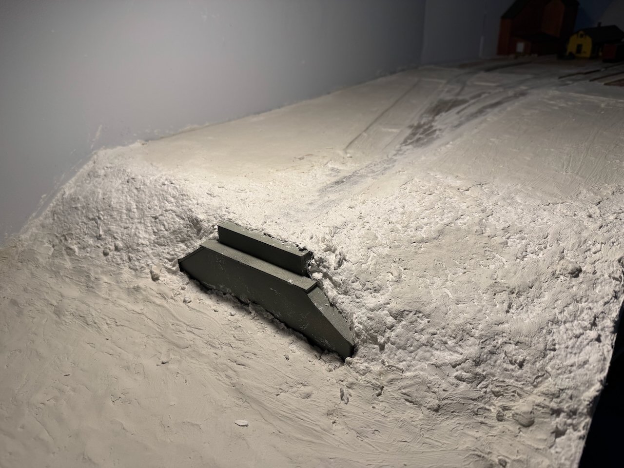
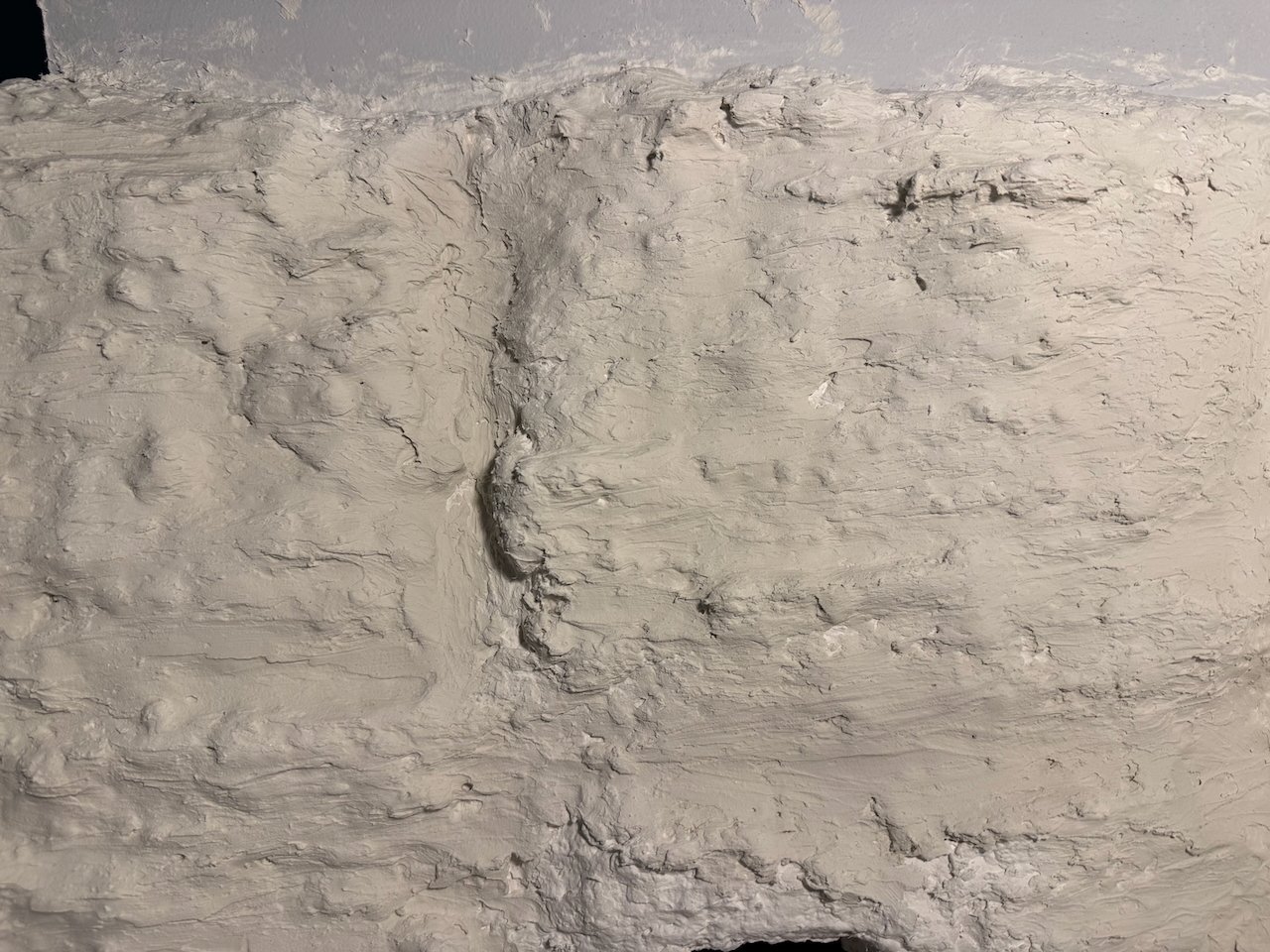
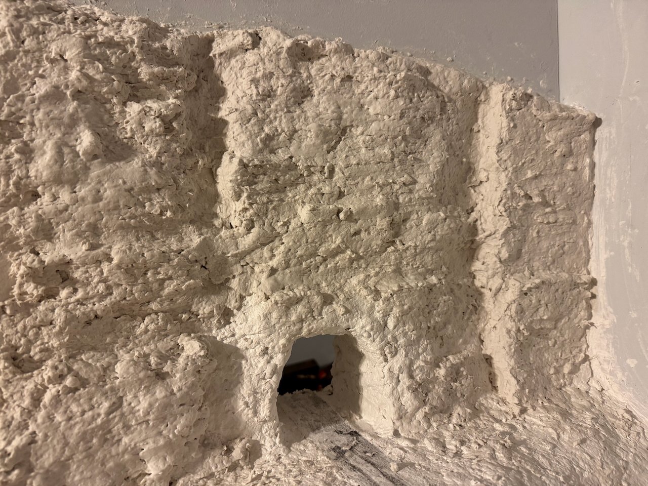
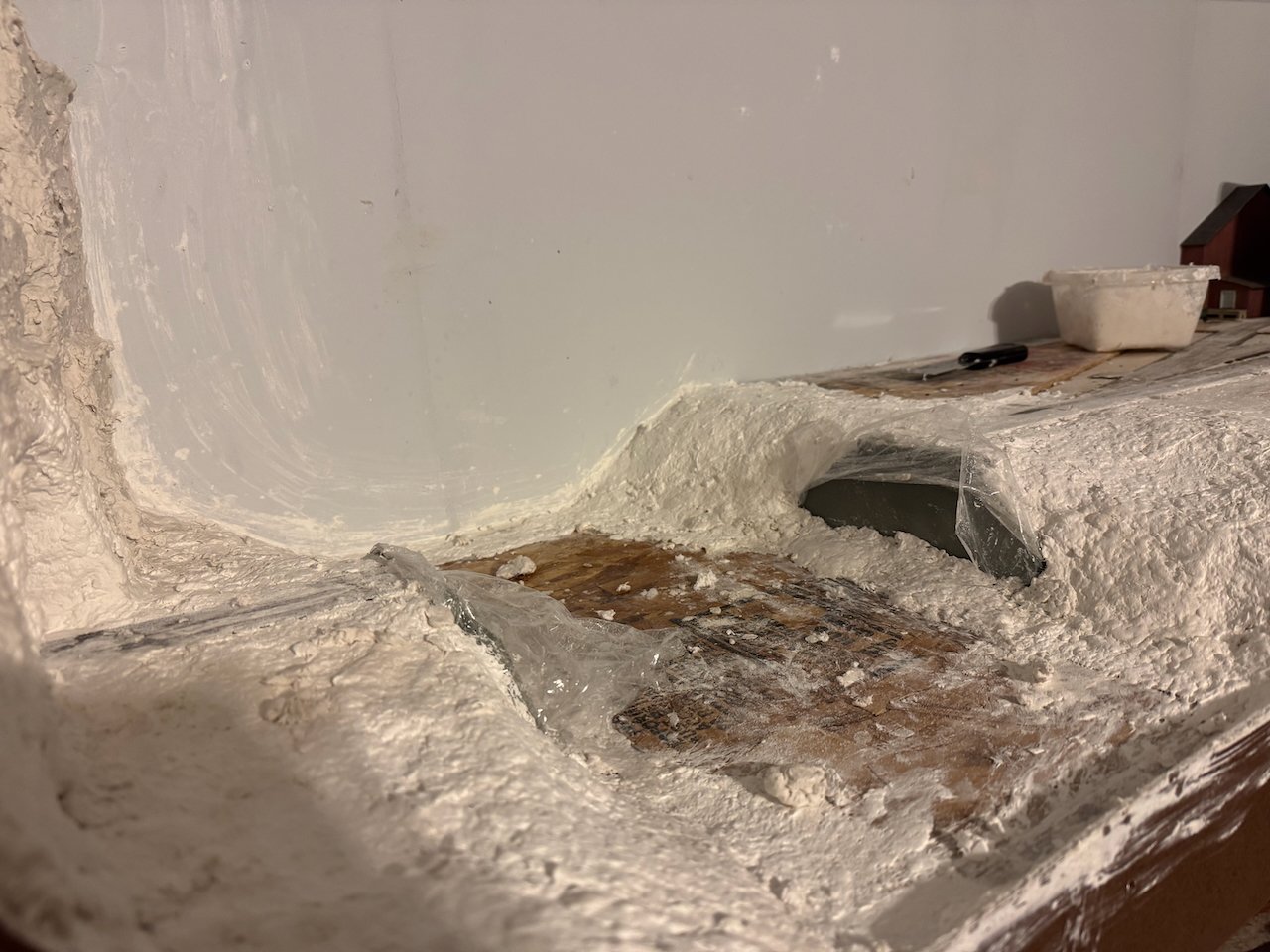
Found a bit more time this weekend for another round of scenery work. This time I used a patching plaster from the hardware store to spread a thin coating over the rock work, using my fingers and other tools to make a finer bedding-plane texture than the coarse plaster allowed. This smoothed out the surface a bit and gave it a more complex texture that I like, though I'm not sure it comes through well in the photo. It's meant to capture the finely bedded, pitted surface of this limestone. Once I start adding color I think this will really come alive. I also filled in the creek bed and some of the flatter area to the right. Once these areas are fully dry I'm going to go over them with a fine sanding block. Anything that isn't rock bluff will be covered by various scenic materials anyway. And here's one more view of this scene. Really looking forward to getting some color on this whiteout!
- 264 replies
-
- 13
-
-
That's lovely.
-
One thing I've learned over time is that small mistakes on models like this tend to be overwhelmed by the greater majesty of the complex finished product. This model certainly qualifies; it's gorgeous to look upon and any oddities you know about can be conversation pieces with knowledgeable visitors.
-
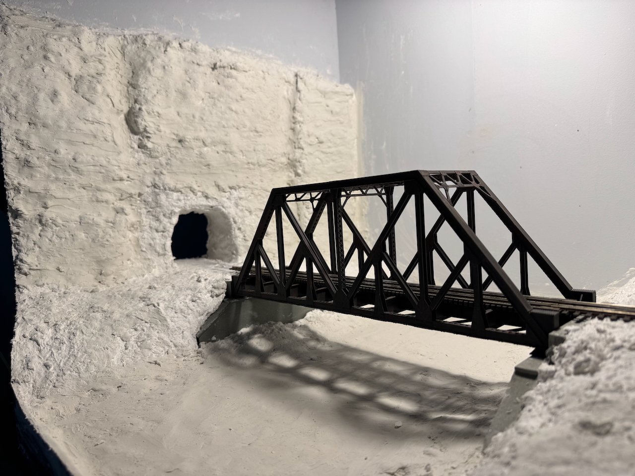
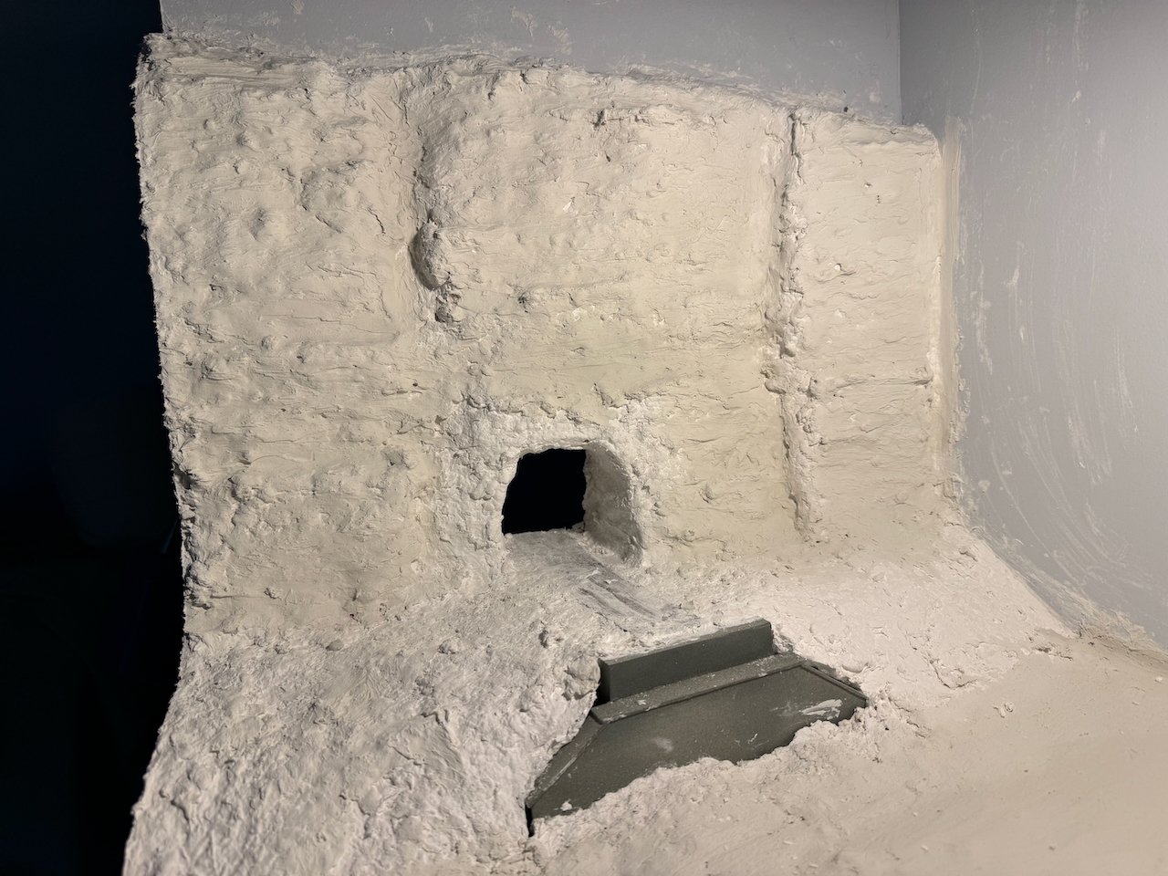
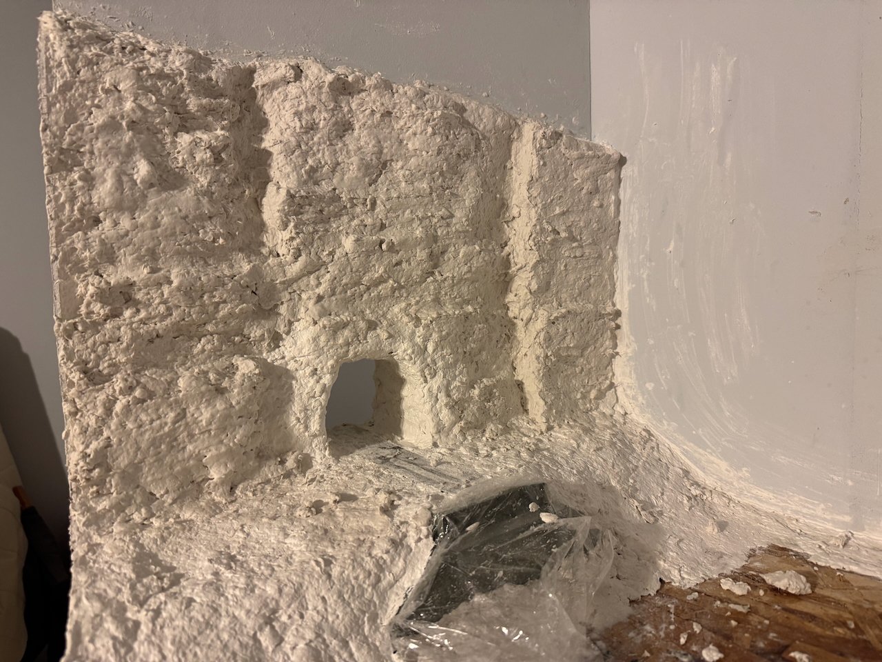
I managed to steal an evening and do a little scenery work. This is a first round of plaster on the bluff face hosting the Rocheport tunnel along Moniteau Creek. Here I'm trying to get the basic shape of the bluff in place with some underlying geologic structure, such as the roughly horizontal bedding, various vertical joints breaking up the rock face, and the more chaotic rock texture right around the portal (both because of blasting and because the nature of the limestone changes there for technical reasons I'll maybe nerd out about at some point). And the real thing: Also made progress on the creek's banks: Next step is to finish sealing in the creek bed and do some touch-up and additional detailing on the bluff face. When I'm comfortable with its texture I'll start first coats of paint. But this at least shows you I haven't completely stalled!
.jpeg.bf358e0b1f2013822bc916f7dd7bfc17.jpeg)
- 264 replies
-
- 13
-
-
Phrasing, my friend, phrasing...Don't type stuff like that where Maggie can hear.
- 732 replies
-
- 4
-

-
- Lula
- sternwheeler
- (and 1 more)
-
OK, now, here I'm going to up and say that you're flat-out wrong. That's a delightfully quirky little vessel, all the more so because she's truly quirky in that she's unique. Rather than just replicating another vessel's quirks, you made her your own. Cambridge English Dictionary: "Quirky: unusual in an attractive and interesting way". That's the very definition of your Lula. In all your prep work for the upcoming surgery, how long have you budgeted for training your sister to finish detailing and weathering for you? Not to mention keeping up with MSW on your behalf. Priorities are priorities, you know. I keep expecting to see a strand of spaghetti running between them...
- 732 replies
-
- 4
-
-
-
-
- Lula
- sternwheeler
- (and 1 more)
-
I love that you're doubling down on the #616 joke I started. Boat looks great.
- 56 replies
-
- 3
-
-
-
- Lindberg
- sternwheeler
- (and 1 more)
-
Keith, thanks for the update. I know it can be hard to share stuff like that and it's thoughtful of you to worry about US! Certainly the "it's your model" rule applies and no comments were intended as criticism, just ongoing discussion of the modeling process. It is and will be a fantastic model! I know it'll be extra hard on you trying to prepare for Maggie's welfare while you're under the knife, so hang in there. We're all pulling for you.
- 732 replies
-
- 6
-
-
-
- Lula
- sternwheeler
- (and 1 more)
-
Very nice job upgrading ol' #616. I love this kind of modeling!
- 56 replies
-
- 3
-
-
-
- Lindberg
- sternwheeler
- (and 1 more)
-
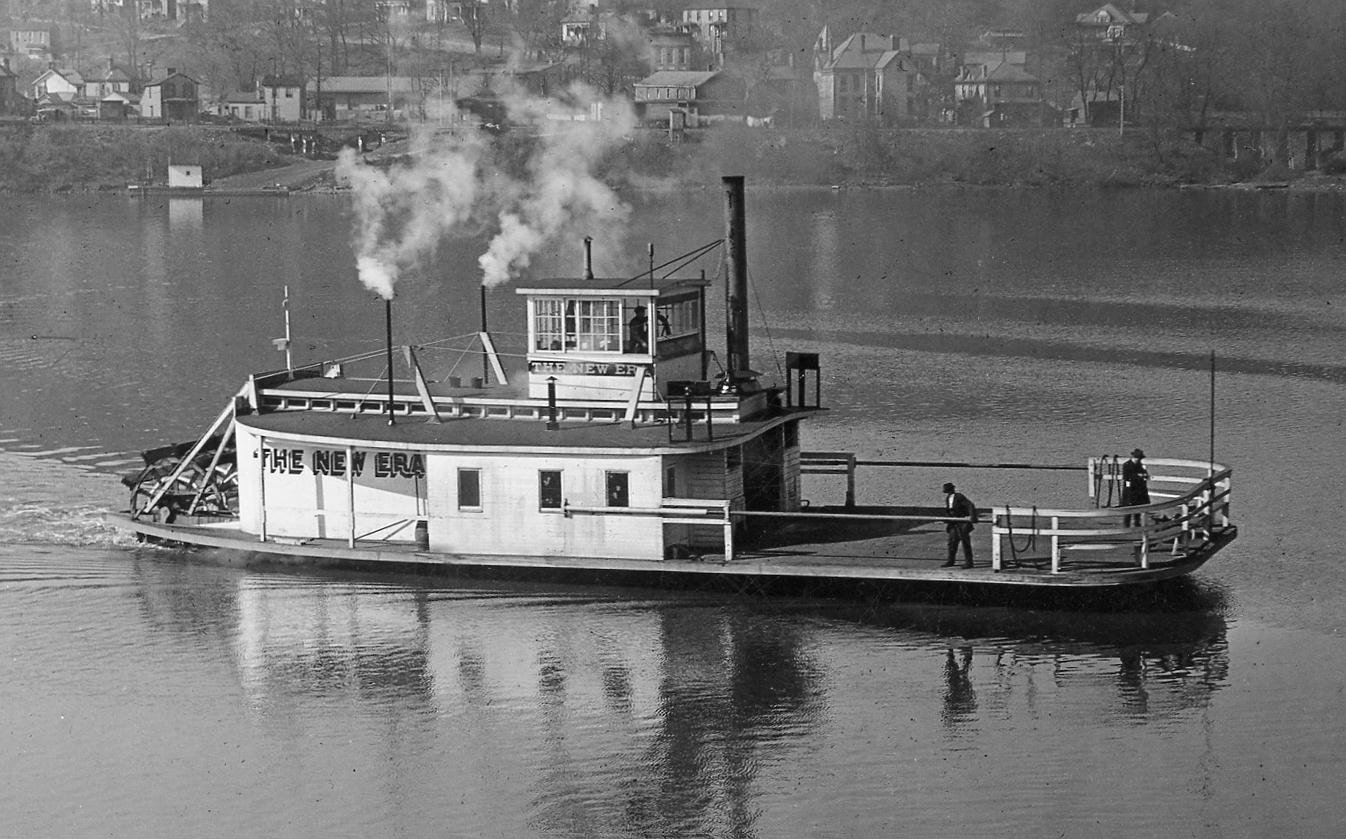
Keith, I have a question: do you have a photo of Lula from the front? The only one I can recall is the one from the starboard rear quarter, but you of course have far greater knowledge of the resources you're working from. The reason I ask, is that I'm interested in the idea that Lula had separate windows (whether three or four) on the forward wall of the pilothouse. Typical riverboat practice (which I'll openly acknowledge does not preclude any other practice) was to leave the forward "window" as either a full open area or with a bare minimum of visual interference (for example, no posts between windows). For obvious reasons of visibility. To my eye, when I look at your rear-quarter image, looking through the side windows, it kind of looks to me like Lula has the standard wide-open forward pilothouse. Like these examples on two other river ferries: So I'm just curious about your approach here, with the open acknowledgement that I may well be wrong in Lula's case because you know her far better than I do. Regardless, it's really fun to see her superstructure move toward its final shape!

- 732 replies
-
- 7
-
-
-
- Lula
- sternwheeler
- (and 1 more)
-
Hopefully in a few years you can!
-
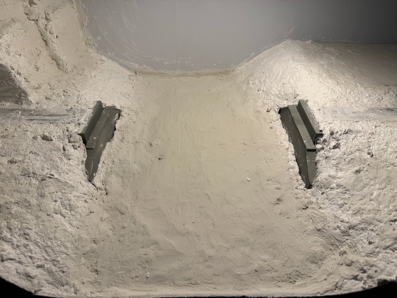
Paul, great question. This layout will run up to three passenger trains and four freights each way during a single "day" operating session. If the staging was fully automated I'd need 14 separate staging tracks and at least that many locomotives, an expensive proposition in both space and purchases. Instead, this is designed as a "fiddle" yard, meaning that one operator is tasked with actively remaking trains by hand as they depart and arrive. This lets me reuse fewer locomotives and cars far more efficiently and creates an interesting job. So that duckunder is how the staging operator (essentially a dispatcher) accesses that area. It's hidden behind the backdrop and big enough to allow a standard desk chair. The out of sight setting helps create the illusion of distance, that trains are entering the main layout from locations far away. This lets me get away with five staging tracks instead of fourteen, which would be impossible in the space I have.
- 264 replies
-
- 10
-