amateur
-
Posts
3,533 -
Joined
-
Last visited
Content Type
Profiles
Forums
Gallery
Events
Everything posted by amateur
-
What type of CA do you use? I only know the thin, rather slow setting glue in nasty little tubes. Jan
-
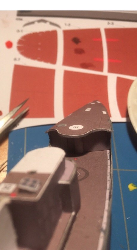
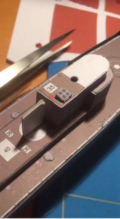
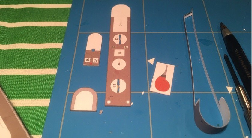
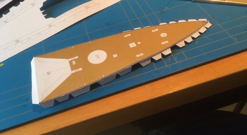
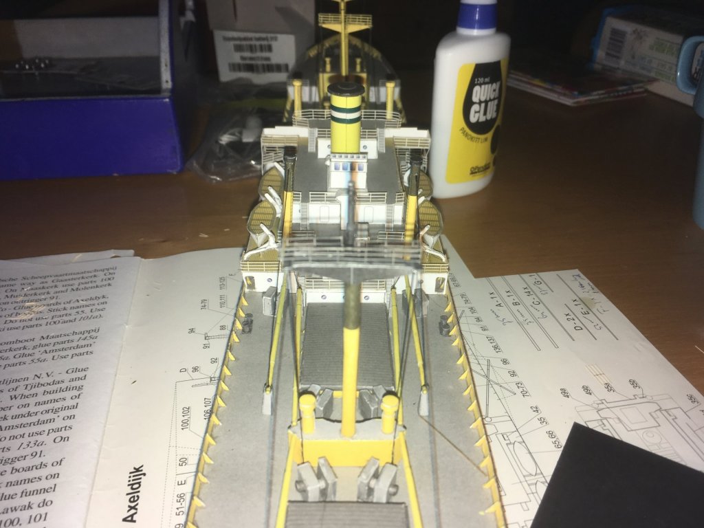
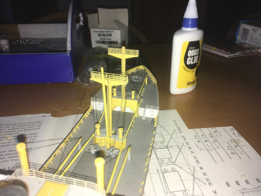
Todays wether wasn't that good, so the planned day out turned out to be a short day.....on the bright side: some building time. the superstructure turned out relatively OK ( the rounded side of the deck slighly oversized, so i was short of .5mm. Used a spare piece to fill in. Viewed without close-up lense it is passable next up: strip around the fore deck. Around 1.5 mm wide, 5 cm long. glued in three pieces (starting from the centre) it covers the ugly paper edge of the deck. I still need to add the column under the deck. And another trying part (at least, for me..,) close-ups should be forbidden.....;) it looks pretty OK in real life, as do those 4mm hatches for the coal bunkers. Jan

- 64 replies
-
- 3
-

-
- v108
- digital navy
- (and 2 more)
-
Oh, an I forgot one: patience. I tend to let go before the glue fully grabs. that increases the problem Jan
- 64 replies
-
- 4
-
-
- v108
- digital navy
- (and 2 more)
-
Yeah, that is what Ithinktoo, but the hawseholes are not simple holes in thehull. They are that 'box-like indentations in the hull, to be glued to the hull with four little tabs.... Jan
-
Hi Dan, The framing card is just under 1 mm thick, making the laminated card just over 1 mm thick. There is no probl m there. (In my other build, the framing card is a bit thin: same thickness as the other parts). Thicker card would not have prevented this: there is no frame where the hull cracked. the other points you make are my learning points here. (And no, you don't sound toocritical: it is more 'factual') one learning point is the (handling) of glue: the waterbased glue softens the paper (and it loosens the colour layer). That's what happened here: too much glue, sofftening of the tabs, therefore the gap didn't close. I thought that a little more pressure would close the gap, but I put too much pressure on... but as I said: it is my first of this type of model, so it is intended as a practice model. perhaps I should redo it after I finish this version. Jan
- 64 replies
-
- 5
-
-
- v108
- digital navy
- (and 2 more)
-
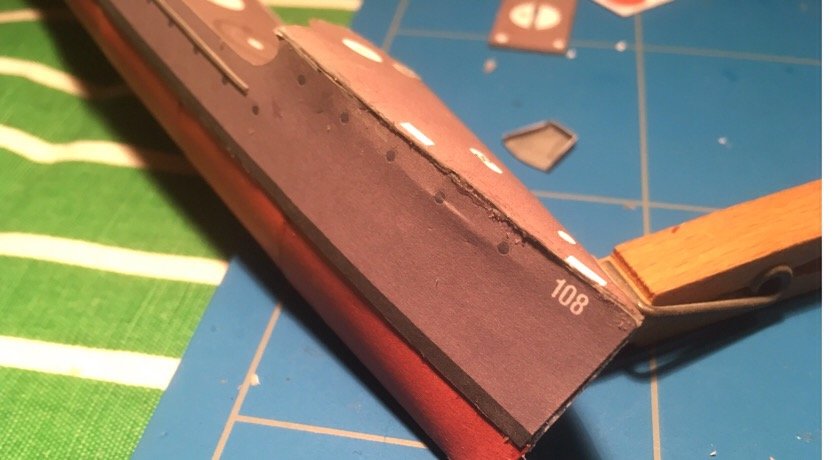
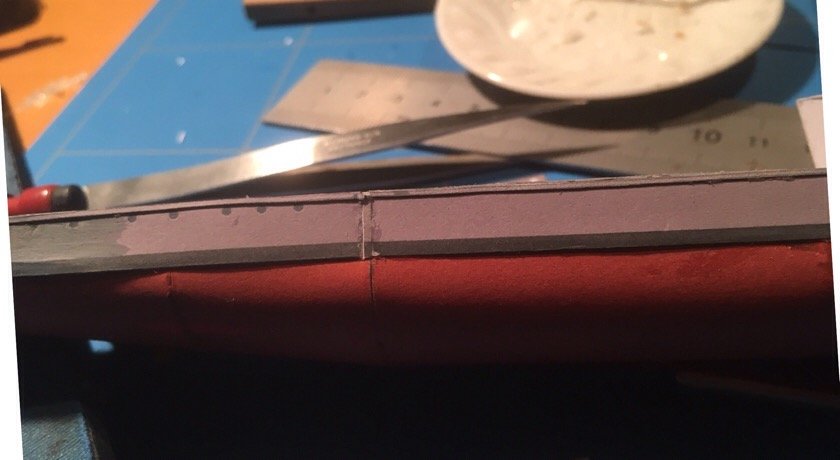
I got the deck closed, but unfortunatedly, the pressure needed for that made the hull crack (just under the glueing tab attached to the hull) and I will redo the superstructure. The parts are ready, but the paint on the deck edge needs to dry before I start gluing (waterbased glue, so it will not grab on a wet / damp surface) both decks are rounded the same way, so I hope that there will be no twisting this time. No building time tomorrow, so plenty of drying time Jan
- 64 replies
-
- 6
-
-
- v108
- digital navy
- (and 2 more)
-
At one a day, your house must be filled to the attic with these ships! Or do you sell? jan
-
It always looks so simple when other people show their magnificent progress. So here is one to cheer you less-gifted modellers up when closing the hull on the other side, it provd that I had 1.5 mm short. I printed the part again to cut a piece of the required length. Guess what: my printer gave an other colour, but next to my not-so-well-executed paint job, it doen't matter too much more of a problem was the first oart of the superstructure. In his tutorial Chris showed how it should look. Well, this is how it turned out. as the base and top floor were severely out of line, this part will be scrapped. Hope my printer will provide me with something comparable... and finally: the front deck: the first tabs are glued, but I am not quite sure how to procede. (And on this macro I see the next problem coming: the tabs are not lined up properly.... Well, it is only intended as a practice model Jan
- 64 replies
-
- 4
-
-
- v108
- digital navy
- (and 2 more)
-
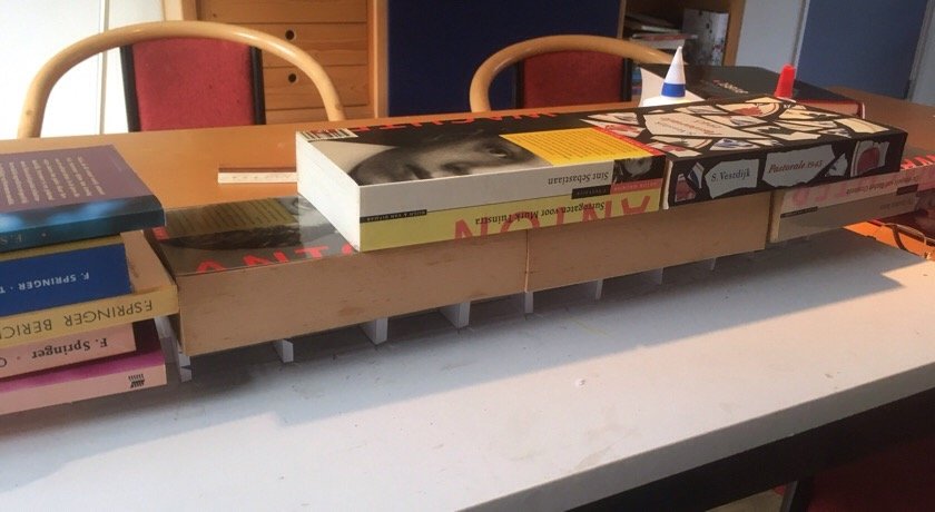
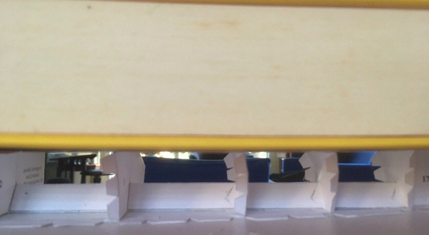
And the weight to keep the deck down. The cardboard is struglling a bit with the weight, but I need it, toget the deck more or less flat. (Although I already noticed with the back-deck that some unevenness remains. it turned out that some (not all) of the frames were slightly wider that the deck, and that there was a very, very slight lengthwise curvature in the hull. So I will need to tweak around a bit with those flaps to get the skin and deck without any gaps. Next up: some edge painting of the decks. (After the glue is dry, so I guess that Ishould take a break for now) (I could switch to one of my other builds, though..;) ) Jan
-
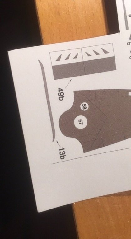
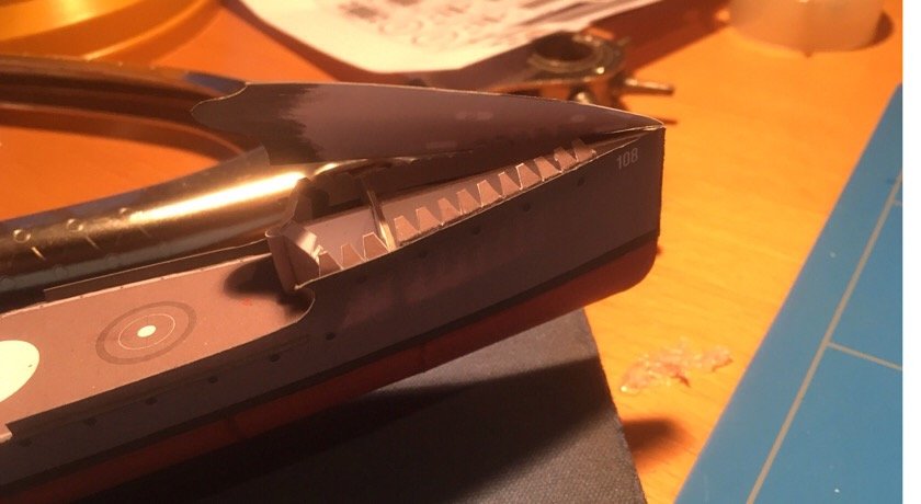
More tabs more weight and a workable flat deck Now thinking over the skinning procedure: the skin goes over lengthwise: stern sction, bow-section, and finally a midship section, that has some margin for error (3 mm ) fun thing is: the stern and bow need to be formed: at the waterline they meet at an angle, at deck level they meet without angle. The sternsection is curved inward, the bow should kind of 'fan out'. There are, hoever no slits cut into the skin to help forming. besides: in the bow section, exactly in the place were curvature is largest, the skin need to be cut where the hawse holes (three of them) need to come. The instruction says: first skinning, next placing these hawseholes, but i cant get to the backside of them after the skin goes on. Cutting the hole before skinning perhaps will cause the skin to kink instead of curve while forming, so i contemplate over the order of appearance I will keep you informed Jan

-
Hi Danny, it is tabs all over. Doing away with them is a bit tricky, so I will try to live with it. I dont like this design: there is no way of checking the length of the frames: the frames did not exactly match the bottom piece. Untill the skins goes on you dont know. By that time, there is no way of correcting....... jan
-
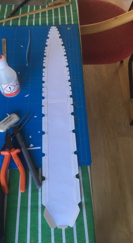
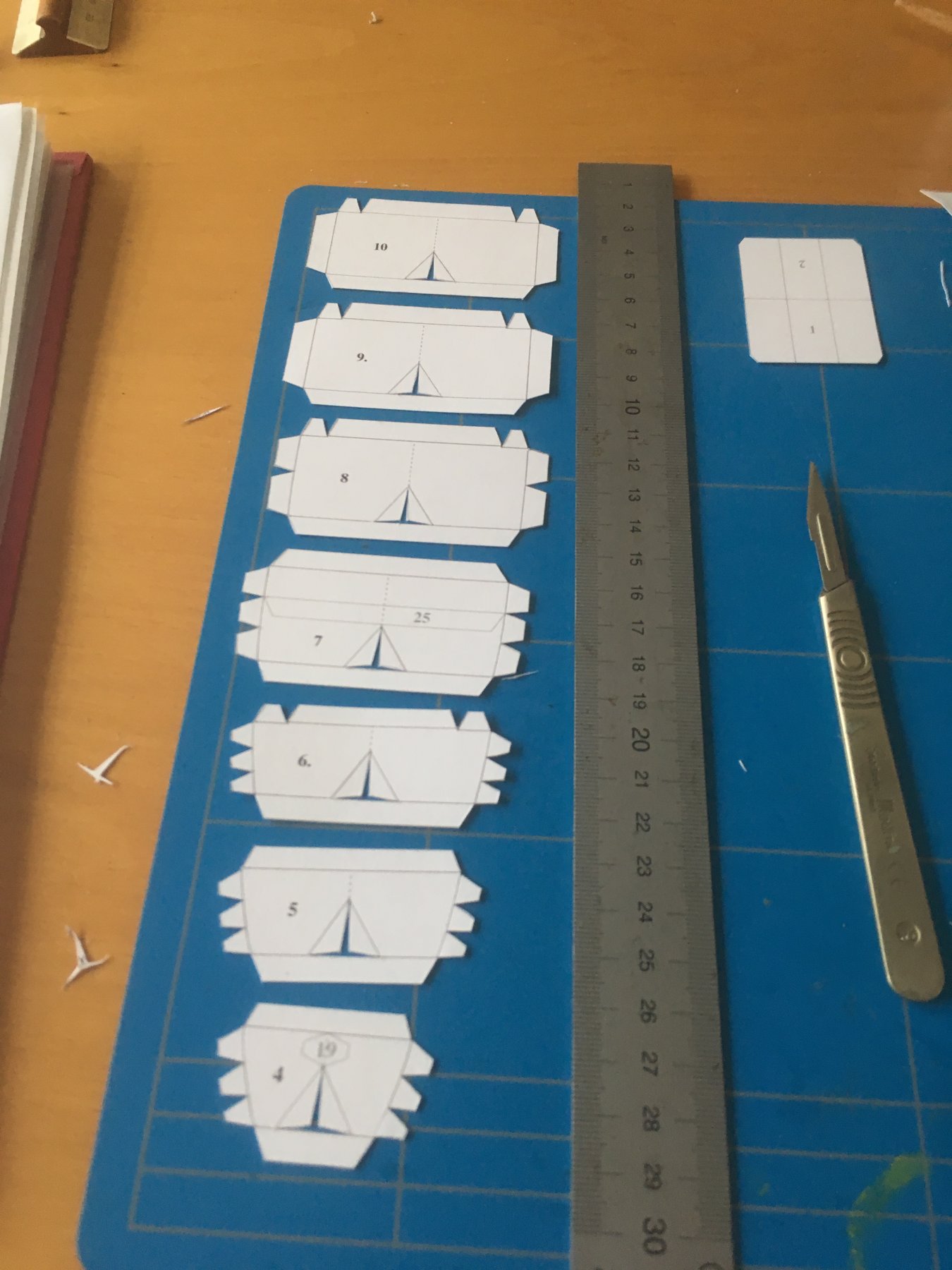
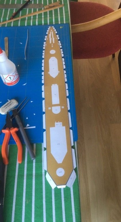
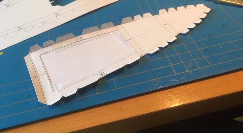
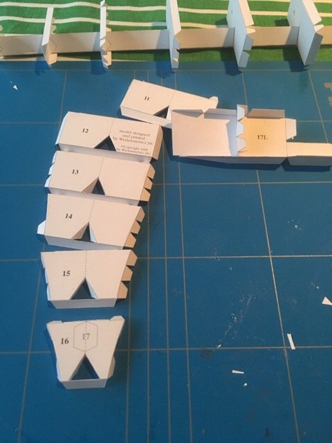
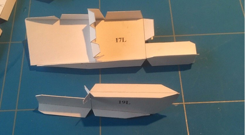
What is a kit without problems? I ran into the first one, and the instructions are not helpfull: the gluetabs are not attached to the deck, but on a separate layer, to be glued under the deck. But it didn't match up: is the deck wider than de hull, is the deckpart too wide, the tab-part to small, the deck too long, or the underlayer too short. I don't know, so i just glued it to the underside. This however did't look good, so i ripped it off again. (Ouch, the glue sets pretty quick). Ishortened the deck by about 1.5 mm, and now they under and upper part seem to match up. I hope the gluing/regluing does not result in a deckthat is very uneven..... and now for thebottom part. The instructions say: attach to flat underground, glue togetehr, and glue frames on top. Yeah....:) Jan
-
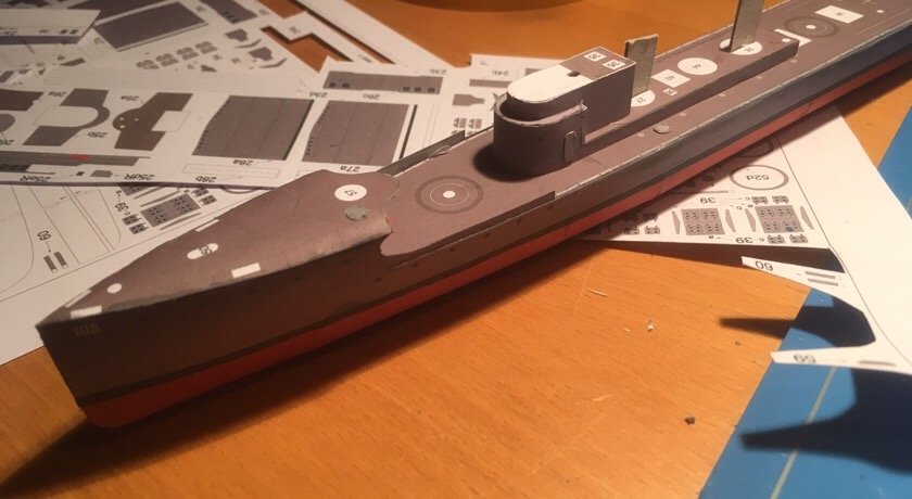
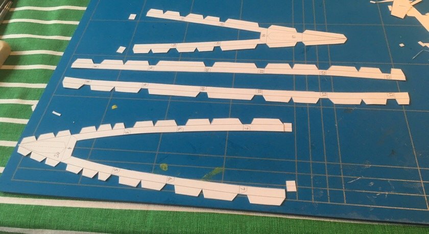
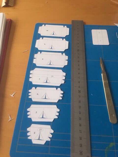
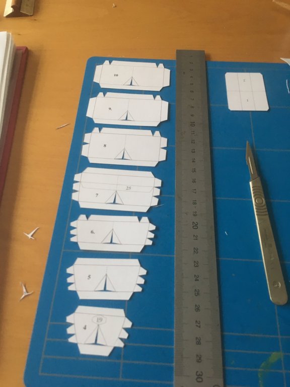
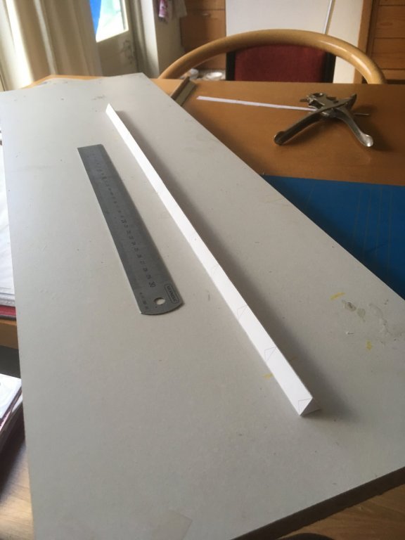
Piet asked me in an other thread whether I would build her pre WW-Ii or like she was in the war. Actually, I don't know which year the kit takes as a reference. De Ruyter had over a very short period of her already short existence a camouflage-print (in dark green and grey). Scaldis also had this camouflage version, but I don't know whether this greylivery. Depicted in my kit predates this camouflage or isthe 'post-camouflage' version. I know for sure that it is not depicted 'as build', because the kit shows the modified funnel. Ihave not searched for other clues yet. and now for this mornings progress. cutting, folding, gluing. t in the last pic you can see another twisting: both bow and stern are two pieces, flaps folded outward, and than glued back to back. Although glued under heavy weight, folded along a steel ruler, the final piece had some twisting. I hope to correct this wen the bottom and top pieces are installed. I like the length to breadth ratio of these cruisers: less than 1:10, just over 6 cm wide, and 70 centimeters long. Definitely more elegant than the large battleships of the period. (The same holds for the two other dutchcruiserrs of the same period: Java and Sumatra) Jan

-
And a neatly folded cardbox is surprisingly strong: see how much weight Danny put o on that deck. Jan
-
Hi Piet, I will build her 'out of the box', but scaldis does not mention which date they use as reference. So..I can't answer your question.... jan
-
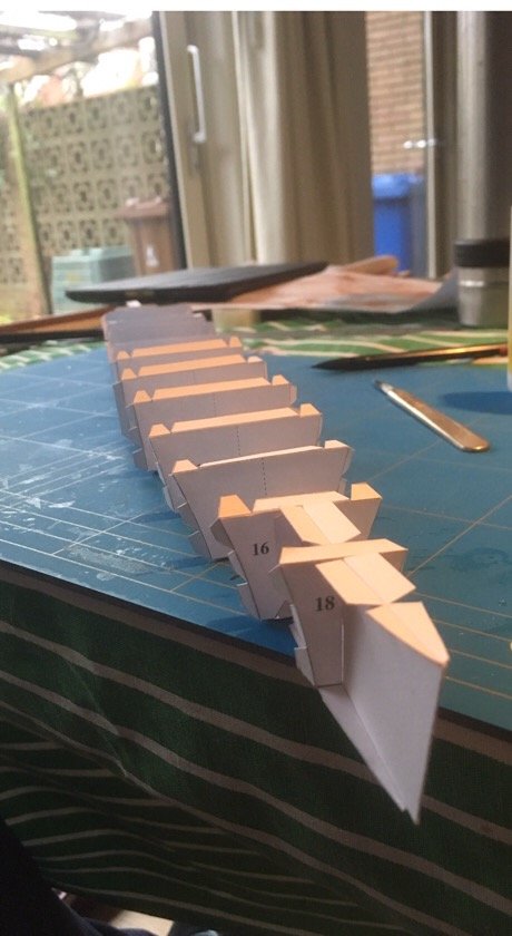
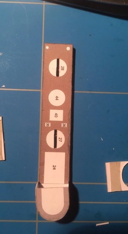
I did the backbone, it is almost straight, and not too heavily twisted. that is the problem using this constructionmethod, any folding-errors, however minute create a twist inthis backbone. and I cut out part of the frames that have to slot over the centra beam. Jan
-
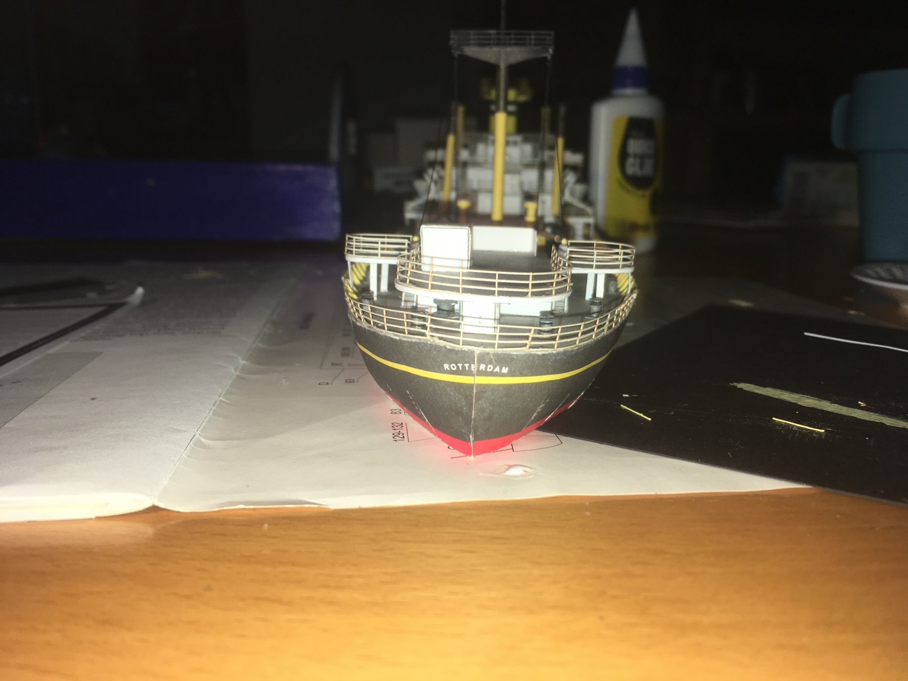
Thanks. The pic was taken at sundown, almost against the sun.... Jan
-
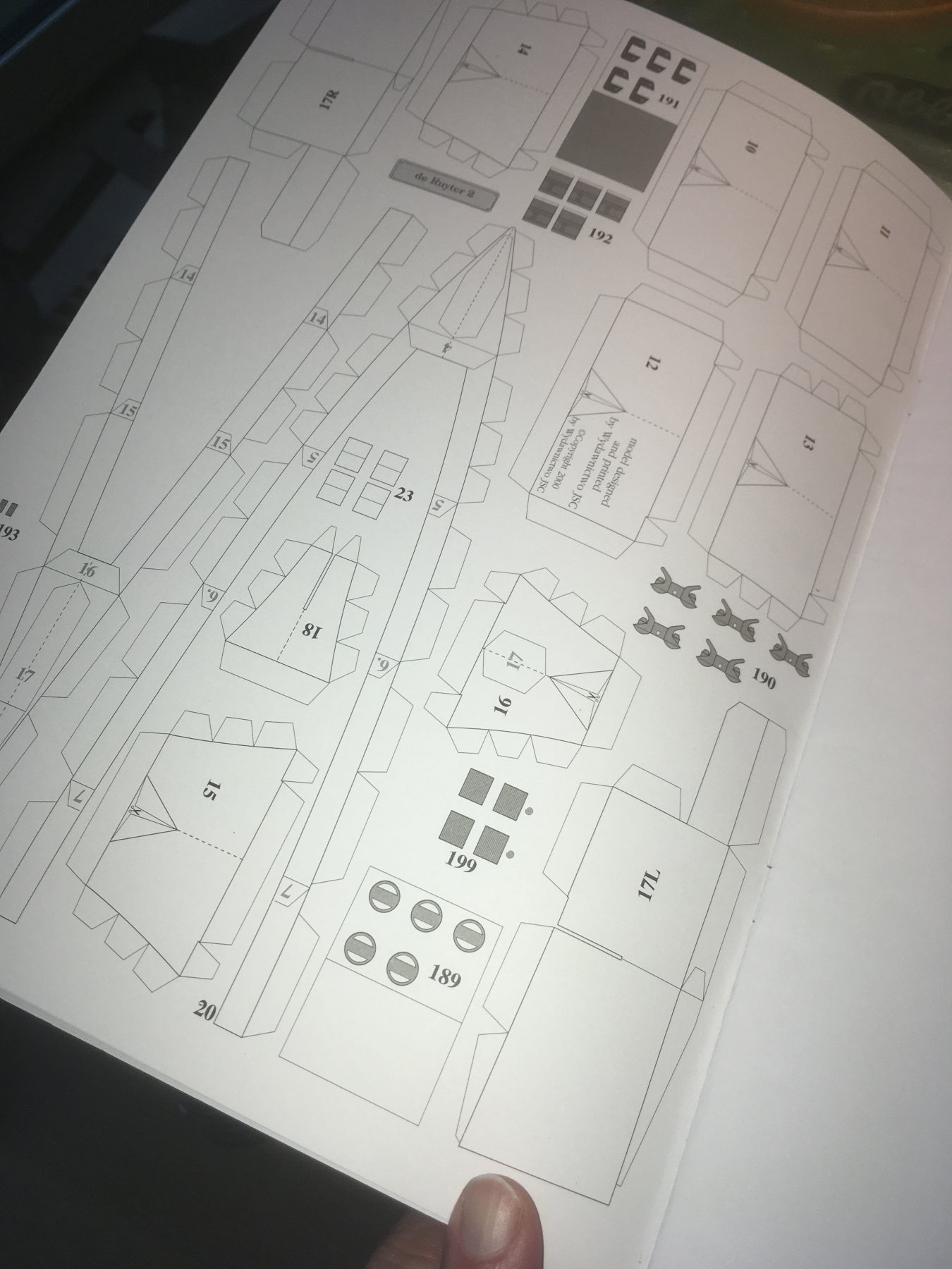
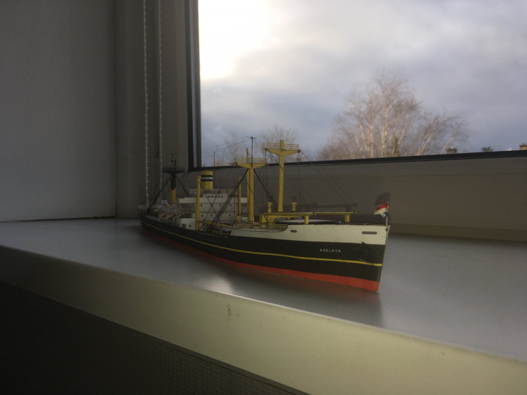
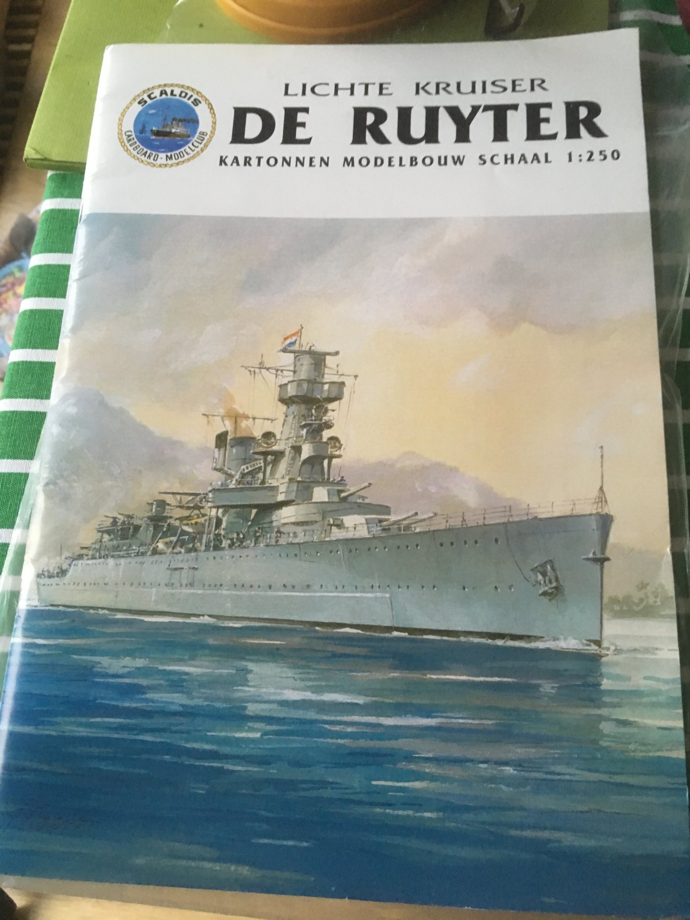
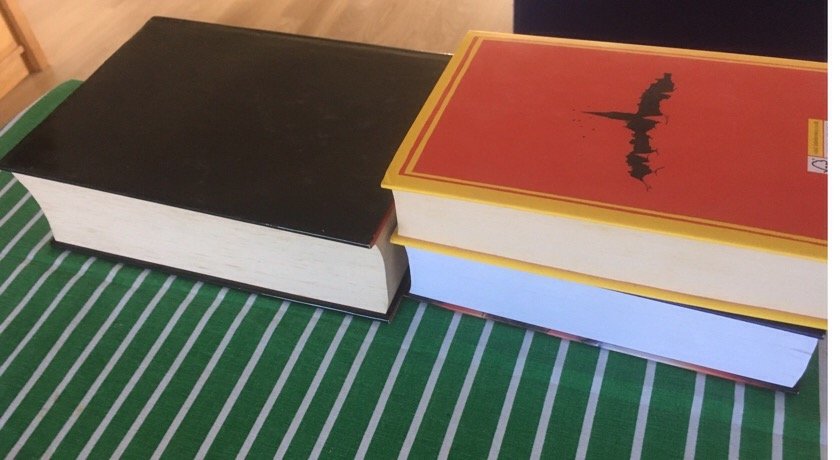
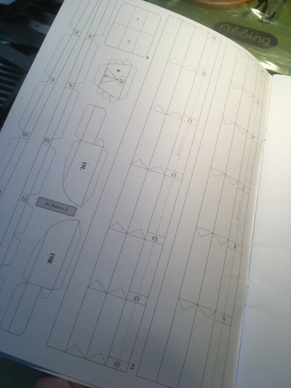
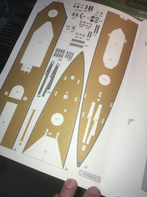
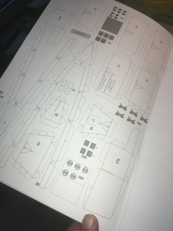
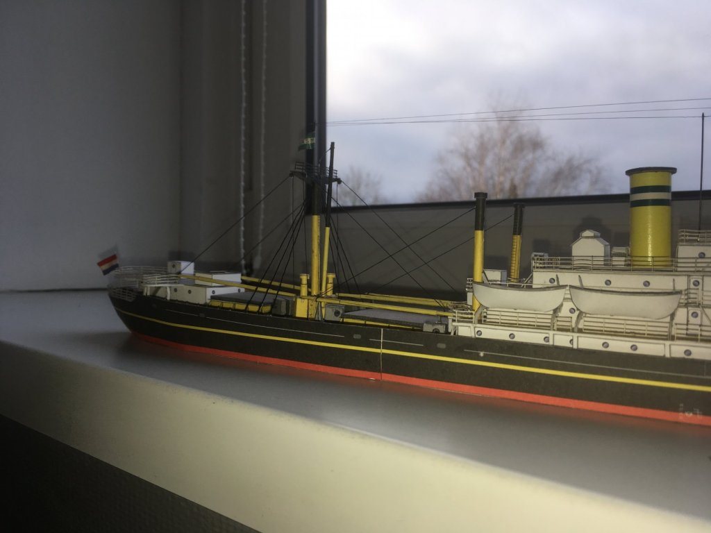
After finishing my model of Axeldijk, I start a new card-model by the Dutch firm Scaldis. It is a 1:250 model of the light cruiser Hr.Ms. De Ruyter. (The model is designed bythe polishfirm JSC). The ship measured 170 meters, sothemodel is just under80 centimeters long. De Ruyter was a ship designed inthe same period as the Dutch cruisers Java and Sumatra: early thirties. I rhink they have an appealing design: long, sleek lines. Hoever, for their purpose, they were a bit outdatedalready at their launch: their armamanet being 7 15cm guns, and a number of machine guns for anti aircraft protection. She also had to Fokker biplanes on board. het warrime crew was 470 men. The ship had an armour belt at the waterline, but that alos was more basedshipdesign inthe interbellum than a match to the modern ships of the early forties. She was the flagship of the combined fleet inthe Java-sea, and went down in that battle in 1942, on februari 27th. The basic design of the hull is comparable to that of many scaldis-models: a triangular guirder that acts as the backbone of the model, the frames are slotted on this beam, deck glued on top, andnext the hull (in threepieces) attached. I will glue a sepearte 160grams sheet under the decks, as with Axeldijk I discovered that the deck remains a bit wobbly, and tends to curve in unexpected (and unwanted) places, resulting in deck-houses not being vertical.... I don't actually like this construcion: it is rather sturdy,but any dolding or gluing errors in that triangular part willend up in a skewed hull (and there is no way ofcorrecting that skewedness). There are some buildlogs of DeRuyter around, but almost none of them reaches the end. I wonder why..... Jan

- 121 replies
-
- 10
-
-
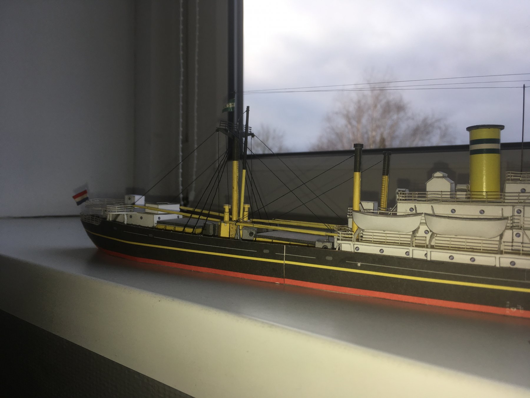
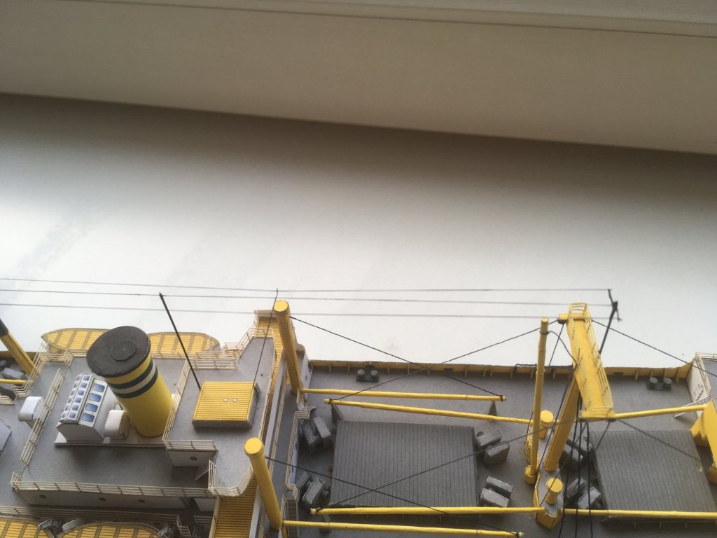
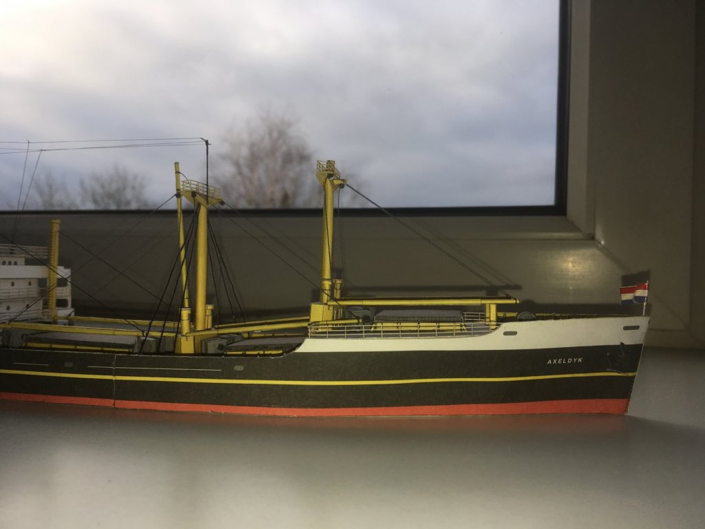
Last night I did the last 'rigging'. As I did not make any eyebolts in the railing, tensioning up was a bit of a problem. Next time, i may try to rig using copperwire, as that does not hase any fuzziness, and is a bit more straight. the antennae are doen with a elastictype or line (EZ-line) easy to work with, but.... the tension was justenoughto slacken the rigging of the cranes. Lessonlearned for the next time. And I need tofind a provider of some decent ca glue. My local shop has only small tubes of rather licquid, but relatively slow setting CA. Besides: after opening, the tube can not be reclosed properly, so each time Ineed CA, Ihave to revisit the shop. Rather annoying.... I did some lousy pics using my cell-phone (camera battery was flat, should redo them ona sunny day, as these pics do not exactly flatter themodel ) For now this log that is not a log willbe closed, asthe model is finished (actually a bit proud: this thing is the first build in over a decade that reaches the end ) I have two card-models more or less going, but Iwill start a third, as that seems to be the easiest one: again a1:250, issuedby Scaldis (and designed by JSC). lLight cruiser De Ruyter (1936). Jan


-
Almost there..... today I did the remainder with f the railings. the stern is a bit of a problem: the railing should slope upward, outward, and curve. Can't be done with a straight cardboard one. Especially while the deck is a bit skewed.... after some nasty words, I am not to displeased with the result (considering it a first...:) ) I also included a steip arou d the deck, and some pillars below the extended decks (as in many pics of the original ships these show up) the railngs onthe cranes needed some colour, I used watercolours. Easy tomix, but a bit hard on the card... I decided to leave out the railings to the stairs: they are not included in my lasercut set, and experiments to do them out of card are not fit to be shown (wrong thickness, wrong colour and far to irregular. Now the antennae and the flagpoles remain. Almost there....:) (Would be a first model completed in ages) Jan

-
Yes, I understand, but she wouldn't be the first war grave in those seas that disappear.... Jan
-
The result is stunning. I was goning to ask for a size reference, until I discovered that is was already there. As soon as I recognized it, my admiration for your skills grew even more Do you work using an optivisor? Jan