amateur
-
Posts
3,534 -
Joined
-
Last visited
Content Type
Profiles
Forums
Gallery
Events
Everything posted by amateur
-
Hi Denis, A bit off-topic, but can you show a pic of that Yamaha? I know the templates, but never saw one done. Jan
-
How did you manage to glue those tiny bits on ? seriously: looking good. I never tried this tiny stuff. Would need some serious glasses to see them I guess. Jan
- 378 replies
-
- 4
-

-
- java
- pacific crossroads
- (and 2 more)
-
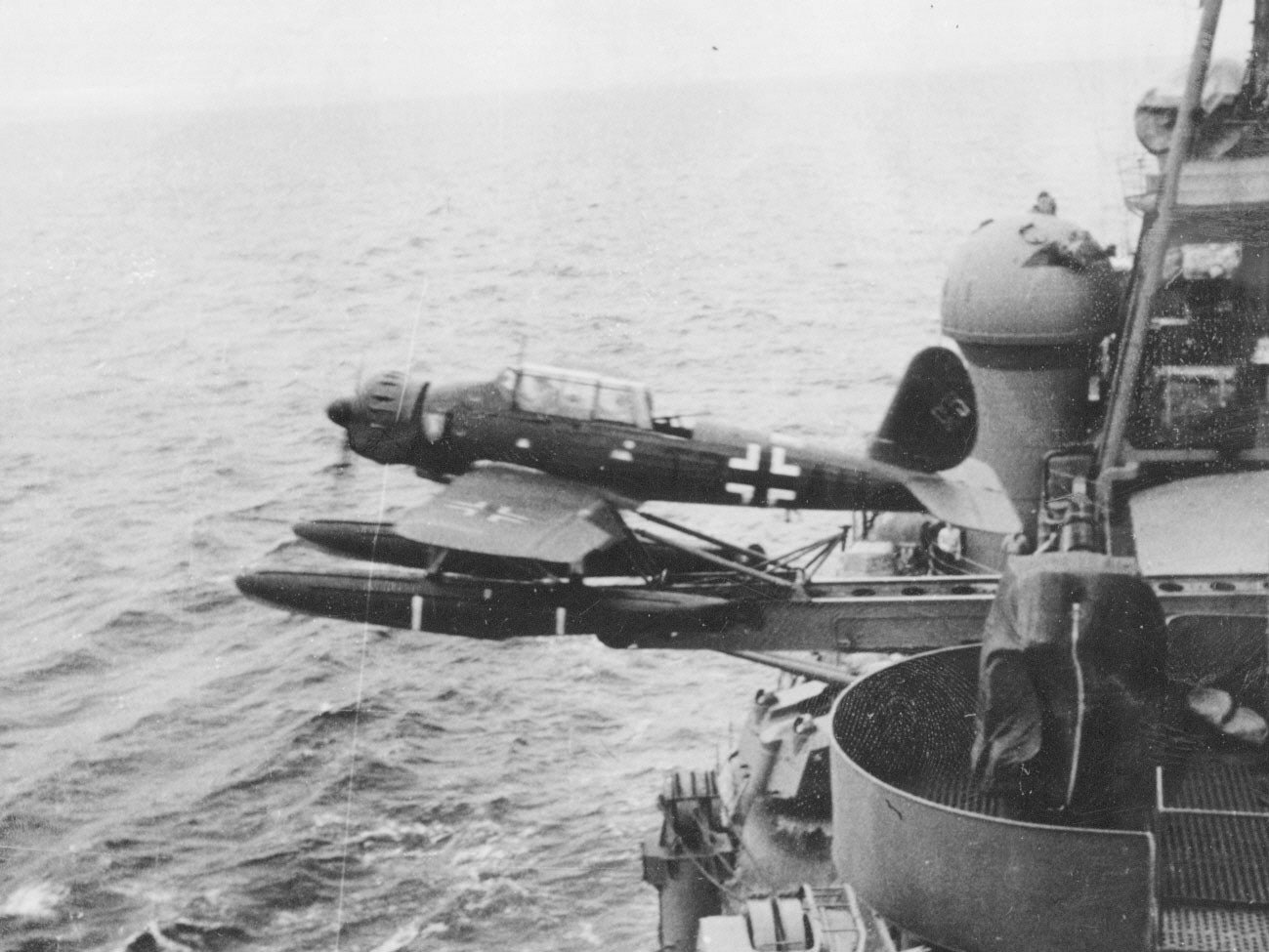
Nice work on the cranes and planes! (planes are very convincing, even in the extreme close-up) btw: as far as the photographic evidence goes: the canopy has norear end. Al pics of the plane show the canopy open (and with a visible gun) Jan

-
Hi Piet, I know that the third one (hrMs Celebes) was cancelled, but I never saw any drawings of her. You know that her lines were to be even better, suggesting that you found a drawing? Jan
- 378 replies
-
- 6
-
-
- java
- pacific crossroads
- (and 2 more)
-
Hi Piet, Thanks for the pic. Didn't know that one. I love the lines of these Dutch cruisers. (actually, I like the lines of the Sumatra-class better. ONe of my favorite pic is the one of Java in Sydney: taken from a low point of view, alongside the hull. Really shows her lines.) I never realized that the 'scerw-protection' could be turned upward: I thought it was a fixed construction. Jan
- 378 replies
-
- 5
-
-
- java
- pacific crossroads
- (and 2 more)
-
Not only is there a lot of puctures, also some films, almost all available though NIMH. Here is a film of (amongst others) hrms Java in Indonesia. Java at full speed is at 8:30 in this video. She could indeed churn up the waves... https://nimh-beeldbank.defensie.nl/memorix/93ea8f6e-5eba-11e1-88e0-deb8a456e588 and this one shows how the plane was lowered into the sea from java's deck: https://www.defensie.nl/actueel/nieuws/2012/02/27/unieke-film-van-hr-ms-java-boven-water-video And this one is notJava, but shows quite a lot of the Dutch subs (mainly o20, but the explanation says that O19 is also filmed and shown. https://nimh-beeldbank.defensie.nl/beeldbank/indeling/detail/start/7?q_searchfield=Hrms&f_objecttype[0]=film Jan
- 378 replies
-
- 5
-
-
- java
- pacific crossroads
- (and 2 more)
-
btw I found this one : https://nimh-beeldbank.defensie.nl/beeldbank/indeling/gallery/start/24?q_searchfield=kruiser+Java a number of pictures. I guess these are also available through MaritiemDigitaal, but they are here at higher resolution. Jan
- 378 replies
-
- 4
-
-
- java
- pacific crossroads
- (and 2 more)
-
But a nice picture anyway I guess I missed it, but is the table smaller than I think, or the model longer? and two other questions/remarks: when the Dutch from your sources starts to become too unfamiliar to you, there are people around on this forum who can translate the second one: do you know who the copyright-owner is for that film-fragment of Java firing? There are some films around in the Dutch navy Archive (NIMH, the Netherlands Institute for Military History/Nederlands Institutt voor Militaire Historie). Problem is that quite a lot of those old fragments are combined into films titled like: "De marine in Indie" Jan
- 378 replies
-
- 4
-
-
- java
- pacific crossroads
- (and 2 more)
-
And another thing I discovered when I started looking for pics of the real ship: there is hardly any space left between heads and deck. So: I had the wrong impressions of the size of the real ship. Jan
-
Hi, Welcome to MSW (should we call you Intex, or..?) With respect to your questions: I suspect that it is not a kit, but a decorative model. Used to be very popular around the fifties in Europe. Sometimes they were intended to represent a certain type of ship, sometimes they were just a mixture of 'ship-like' details. Your model is (I suspect) from that last category: three masted, rigged with tops, square rigged (but I can't get how the mizzen was rigged.) The hull, however, has clipper and yacht-characteristics, but can by no means represent (scalewise) a sailingship: that hull with three masts will tumble over) The superstructure, has some 'clipper-like' design charactyeristics. So: 1. no Spanish armada for sure. 2. perhaps no one-off, certainly no kit, and if produced in a larger series, probably the last surviving 3. I guess, but am not an expert: - take pictures of all stages of your work (try to get as much detail on the rigging you can still get before taking it apart) - try to take the whole thing apart (especially the damaged parts without using brute force) - clean the parts and repair (not overpainting, but filling in the missing parts) - put everything back together. The other route is: try to put everything together without taking apart, and fill in the missing gaps. The result will be a very nice decorative model with a story. Not a museum quality ship model. Jan
-
Yep, I did what all beginners do: follow the manual: Glue part to deck, next build the forward structure, glue to deck, adjust the connecting tabs and glue. As the deck isn't completely flat, the very slight pressure of my fingers was enough for the gap to hide. Once the parts were glued together, it showed its real size..... I have some spare grey, so I will check what I can do. Not before next weekend, though.... Jan
-
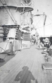
It surprised me how many pics of Java and De Ruyter exist, compared to all ships before and after those two. Same for the subs build in that same period. must be the combination of the building of major ships, and the rise of (cheaper) photography. Jan
- 378 replies
-
- 5
-
-
- java
- pacific crossroads
- (and 2 more)
-
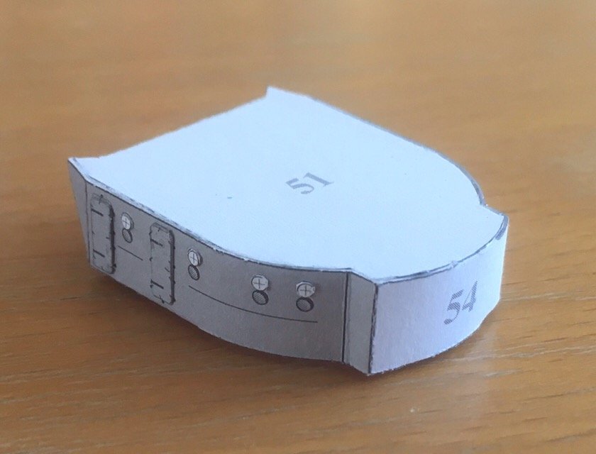
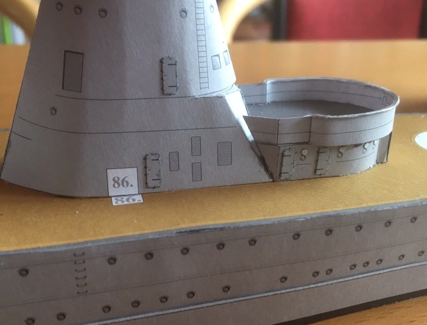
After some contemplating (at work, shouldn't do that ) I discovered what the problem is: the conning tower is slightly too wide, and that also applies to that forward structure. But I tried to get the forward building into the white area painted on the deck. That makes the wall slightly non-vertical, resulting in a gap on the upper side. Have to think whether a total repair does more harm than good, compared to the fix (version 2) Danny described above. (Quite a lot of tabs on the underside ) Jan
-
The ship had a wooden deck, so painting it 'wood colour' is not a bad idea (and like the pics that Piet showed, this one is also available through maritiemdigitaal, unfortunatedly, al those pics are only low-res.....) Jan
- 378 replies
-
- 5
-
-
- java
- pacific crossroads
- (and 2 more)
-
Hi Dan, I contemplated option 2, but discarded it for several reasons. 1 the deck ontop of the forward building fits very nice against the conning tower, it would make a large adaptionto get that one fixed, and Idon’t know the margins there: on this deck a gun will be mounted. 2 despite the small misalignment in the sides (apart from the whole constructionbeing too wide), the margin I have lenghtwise is smaller than the gap. Shortening will create another problem. 3 the gap is more pronounced on this side, and less on the other. So filling it will be. ,(I have some lefftovers from the hull, and a nice square of ‘reserve grey’) Jan
-
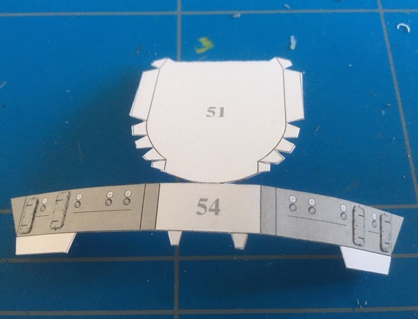
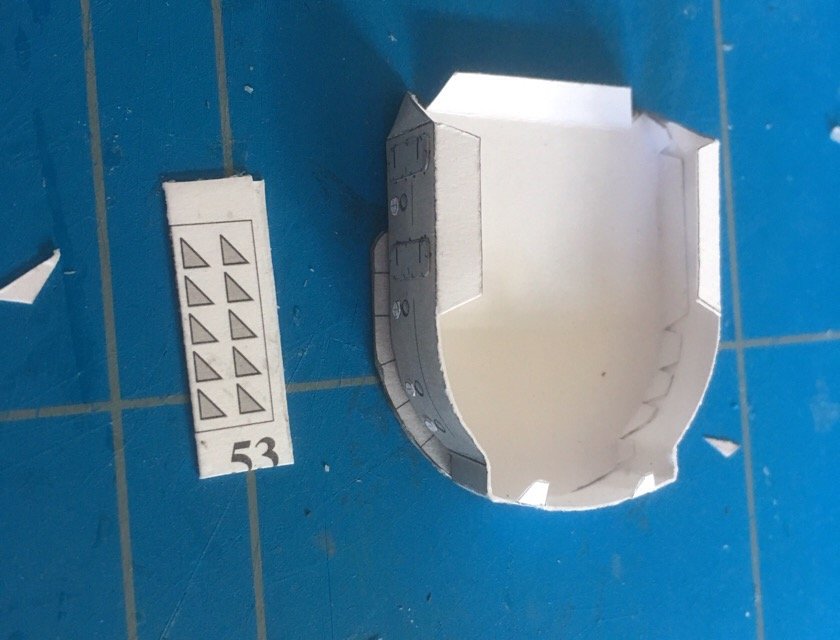
Today I did the nxt part of the superstructure. It was not a complete succes, but I don't know where I went wrong. The forward part of the superstructure( on which a gunturret will be installed) consist of a wall, with a false deck. that one posed no problems then a deck is build upon that, with some minor parts below. And no, those didn't fit into their assignd places. Doorst, windows, everuthing is interfering.... But the forward railng did fit quite nicely.. not to Dan's standards, but I am pretty contend with it. but then....it just didn't fit to th main structure.it is 2mm too low (the deck does not cover the white area in front of the main structure, and the horizontal oine should run level around the whole structure. Yeah....tell me where the error is besdes,the 2 mil gap between tower and railing should not be there,. But is is, and it won't go. strange both parts (tower and forward gun position) went together without problem. I guess they didn't pay attendtion enough in their prototype build....) Jan
-
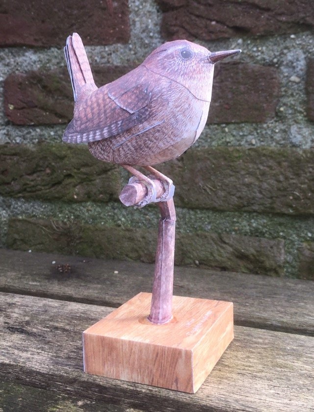
Wren by amateur - FINISHED - 1:1- CARD
amateur replied to amateur's topic in Non-ship/categorised builds
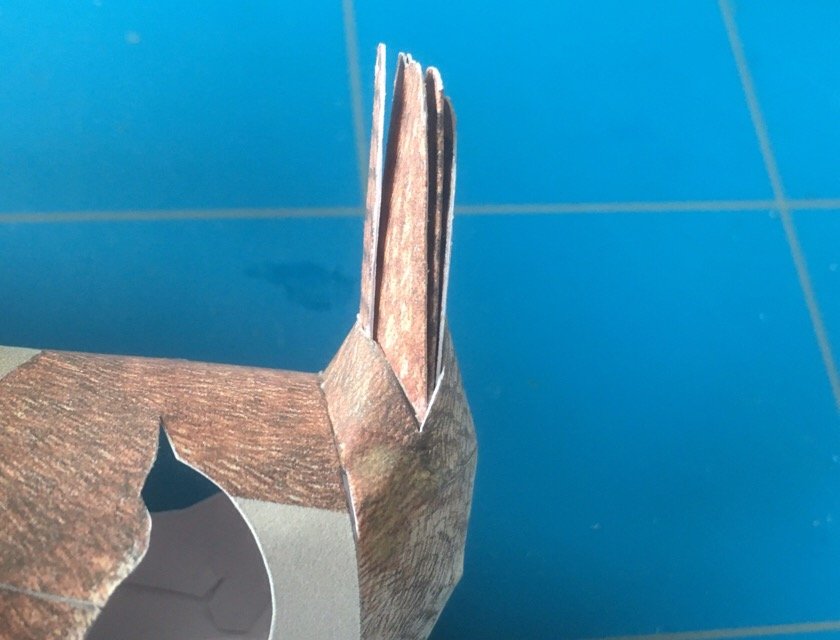
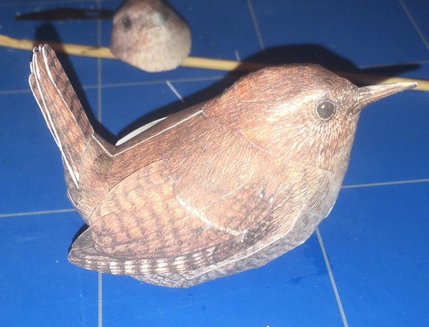
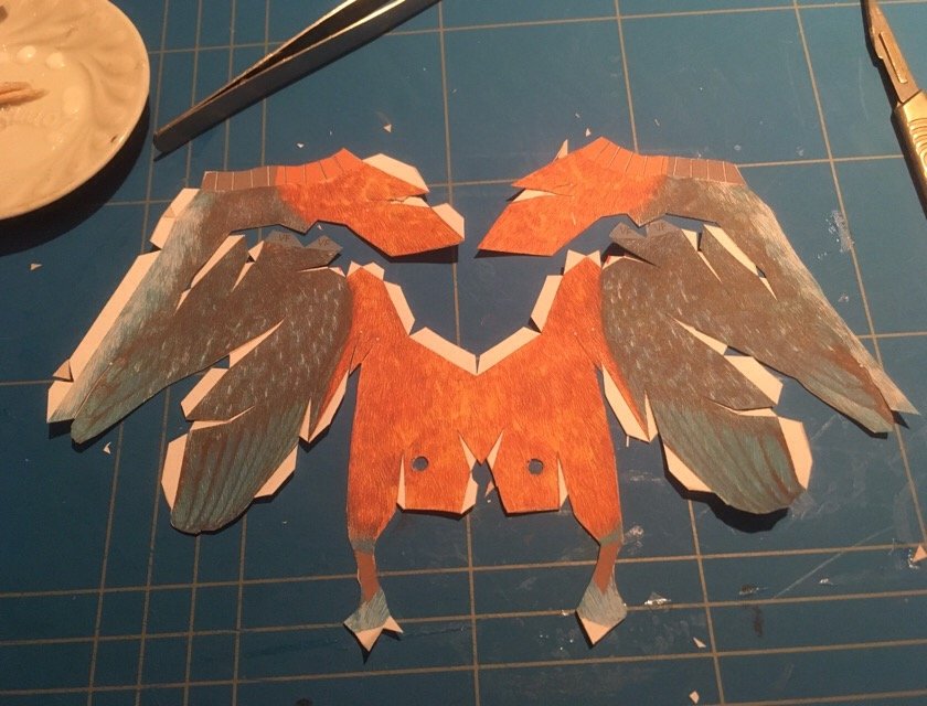
And the finished product, sitting on a paper branch. I hoped to show you the next bird, nut that one didn't suucced (yet). The head didn't fit, and in trying to let it fit, I crushed the body. But I'll restart (next weekend). Here it is before crushing (even before glueing) Jan
-
Interesting new model ship company
amateur replied to Erebus and Terror's topic in Wood ship model kits
Pretty sure about that: see what google translate gives as the (pronunciation of) the word 'clone' translated to Japanese sounds pretty much as couronne,. the framing of these kits more resembles the englishdock-yard style (simplified, non structural frames) than the fully frames models that try togive the real structure. I still don't know whether or not I like these all pre-milled kits..... Jan -
Without any deep thinking: could a half tube be made like a profle, from square srock, usung a scraper? Another thought: sometimes plain paper (the thicker version) can be a alternative for PE-parts. Printing card is not too expensive, and by letting the custeromer cut the parts from the paper, you don't have the laser cost and time (and the customer can go to the copyshop for spares )Or are the parts needed too small/complex to make from paper? Jan
-
No , apart from edgepainting, there will be no painting involved. Ah, well, the laser cut cardboard requires some paint Jan
-
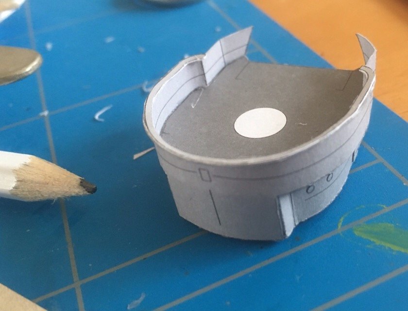
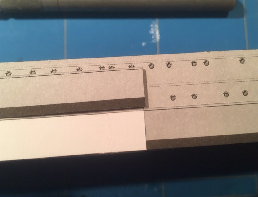
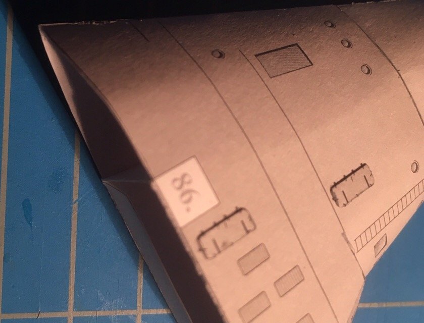
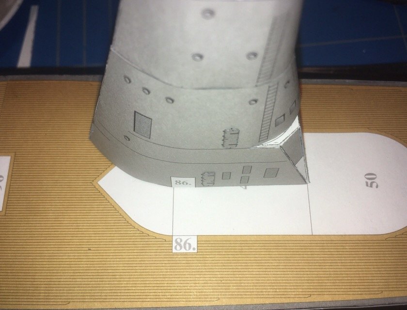
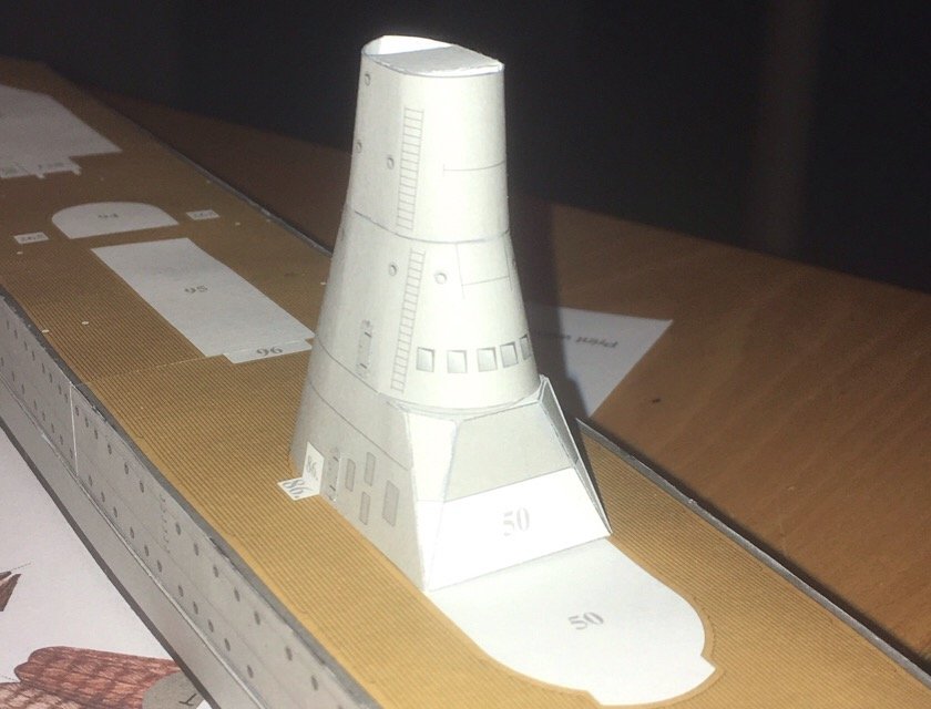
Today it was the other side. and guess what: here the white strio was acentimeter too long, but the grey one did fit almost perfectly. JSC is getting me confused next the conning tower is to be build. It is constructed around a blocklike structure (forgot a pic...). Doors are doubled, but all the remainder is just printed (windows, ladders, etc) Again some confusion with the length: that will never fit.... But it does give a nice feeling to have some superstructure Jan
-
Wren by amateur - FINISHED - 1:1- CARD
amateur replied to amateur's topic in Non-ship/categorised builds
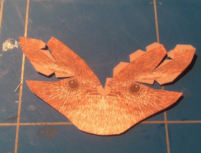
Almost finished (but not completely: the bird needs a brach to sit....) First, a tail next, a new head (the first one didn't fit without damaging the body) and finally, the marriage of all parts into a proper bird I took a branch from the garden, but that didn't work: a real bird doesn't need a horizontal branch. This one does..... Jan