trippwj
-
Posts
3,156 -
Joined
-
Last visited
Content Type
Profiles
Forums
Gallery
Events
Everything posted by trippwj
-
 I'm not sure I am clear on which dimension you are referring to. The keel/sternpost portion will be gently carved and sanded to a final dimension of 1/8" width (not height). If the section at the stern post is already narrower, then you may be better off to either (1) gently carve out enough (from aft toward bow) until you get to the 1/8" wide and then adding in a filler piece to make up the depth (length, fore and aft dimension) removed, or (2) checking with Model Expo to see if they can send a replacement hull as the one you have is not dimensionally correct. For one example of how the shaping and fairing of a Phantom has been handled, take a look at the build by Elijah here http://modelshipworld.com/index.php/topic/12376-phantom-new-york-pilot-boat-by-elijah-model-shipways/?p=402720
 -
Coming along very nicely, Jack. I am impressed with how well the rails have come out - they look smart!
- 250 replies
-
- 4
-

-
- willie l bennett
- model shipways
- (and 1 more)
-
Explanation of Dockyard Terms circa 1691
trippwj replied to trippwj's topic in Nautical/Naval History
Interesting observation, Joel. Question - which vessel are you referring to? I presume (always dangerous) that this is from an archeological survey? Analysis - while possible, this would entail essentially constructing a framework to support the entire weight of the vessel while preventing the movement or deformation of the structures to allow the removal and replacement of the keel and it's associated structures. The effort to accomplish this would be substantial and I would expect to be able to find some record of it being done. Follow-up question - any indication in your research where this would have been done and when? Ahh, the joys of research. Always another trail to follow! -
Nice looking work, Sjors. I had to look three or four times at the gratings - that second gratings picture looks like there is a gap in one of them but no sign in the first shot. Phew!
-
Extracts from A Commissioner's Note Book, Annis 1691-1694 Laughton, J.K., W.G. (William G.) Perrin, C. Lloyd, and N.A.M. Rodger. 1912. The Naval Miscellany Vol. II. Publications of the Navy Records Society. [London] : Printed for the Navy Records Society. http://archive.org/details/navalmiscellany02laug. From the introduction offered in the volume: Several years ago the late Sir Leopold McClintock was so good as to lend me, for the use of the Society, a couple of small MS. books which he had picked up in a second-hand book-shop. They had no pedigree, but their origin is clear enough. They are rather thin octavos, bound in smooth red morocco, richly gilt on sides and backs, and with gilt edges, in the style commonly adopted by the Admiralty throughout the eighteenth century, and which, in itself, would suggest that they belonged to some official connected with the Admiralty were it not that the contents show beyond any practical doubt, that they must have belonged to a commissioner of the navy, in the early nineties of the seventeenth century ; very probably to the comptroller, who at that date was Sir Richard Haddock. The second part is my focus in this post - it “gives, from the most approved source, the explanation of a few terms which are of frequent occurrence in the lists of ships and comments on their efficiency all through the eighteenth century, but especially in the early part of it” So, if interested, here is the Explanation of Dockyard Terms (starts on page 146 of the reference). An Explanation of the Terms of Distinction commonly used in the Navy, of Ordinary Repairs, Extra Repairs, and Rebuilding. Abstract [Ordinary Repair is the annual caulking, tarring, rozining and paying sides and decks, masts also and yards ; palpable defects are made good. Extra Repair is more thorough ; decayed planks, &c., are renewed ; all artificers' work is seen to, and the whole carefully overhauled. Rebuilding consists of virtually pulling the ship to pieces and building into a new ship as much of the old wood as is serviceable. This is dated 16th November 1691, and described as signed by the Commissioners of the Navy. To it ' a larger explication and some other particulars from Mr. Dummer of Chatham ' is added, which here follows.] Defects in Ships, how discovered. Without separating the several parts that compose the whole one from another, defects are found either by searching all seams, rents, and treenails with a caulking iron, or by boring into the frame with an auger ; by observing the ship's chambering or reathing(1) ; the pitched seams to crack or spew out its oakum, or by the looseness of rust-eaten bolts. And as the matter is discernible by any of these means, together with a knowledge how long a ship hath been built, so the estimate of charge for repair is made ; and all beyond this visibility is conjecture, and no better to be discerned than is the condition of the vessels within a consumptive man before dissection. 1 Cambering or wreathing : curving or twisting. An Ordinary Repair is understood to be the annual trimming of the ship in harbor(2) by caulking all those parts which lie to the weather, and laying on of pitch or other mixed stuff of rozin, tallow &c., upon the same ; and once in three years at furthest, to dock them and burn off the old matter under water ; to search the seams and caulk them as occasion is and to grave them anew, which is to say to pay them all over under water with pitch or other mixed matter, with rozin &c. And in this ordinary trimming and repair we allow only of putting of small pieces, or of plank where the seams are grown too wide, or where knots or rents or a particular plank too much perished to hold oakum for tightness against the weather or other leakage. 2 i.e. of a ship in ordinary. An Extra Repair is taken to be such a defect in a ship's outward matter to the weather, that their frames cannot be preserved nor the ship fit for any service at sea by an ordinary trimming, without stripping such decayed materials of the outside planking and wales ; also the in-board works about the bulkheads and sides of the ship that lie to the weather ; therewith putting in short chocks and pieces in such part of the timbering of the frame as in this opening and stripping do appear decayed, and to repair the same all anew ; and many times to drive out all decayed iron bolts in the frame above and under water, placing upon the decks and sides an addition of standards, or riders, or both, that never was there before, for better strengthening the frame of a ship under such repair ; and sometimes the ship is sheathed under water, as the occasion calls for it ; and these works always requiring a dock, are finished with a good caulking all over and aying the ship with mixed stuff, pitch &c. for to keep the weather from preying on the materials of the body. Rebuilding is taken to be when neither the ordinary nor extra repair before mentioned will overcome, and so is an entire stripping down of all the out and in-board works, and removing so much of the timber of the frame, beams, standards, knees, &c., as shall be found decayed and rotten, which is many times done to the leaving only one-fourth part of what is in the old frame in the rebuilt ship ; and sometimes it is only taken to be the unmoulding of the frame and the stripping of the out and in-board work, from the top of the sides to 4 or 5 strakes under the lower wales, and to take out the tires of top timbers and upon futtocks, shifting or scarfing (3) the decayed beams and knees, and making the same good again by new material, completing all in-board works and to caulk all over and to grave. 3 When the ends of two pieces of timber are cut square and put together, they are said to ' butt ' to one another ; and when another piece is laid upon and fastened to both, this is called ' scarfing the timbers.' — Falconer's Diet, of the Marine. But here the term seems rather to mean cuttmg away the decayed part and restoring the thickness of the beam by a new piece laid on. Girdling . . . cannot so properly be called a repair in the matter as a supply of dimensions in breadth to the form of a ship that wants it ; and as occasion requires is from 4 to 8 and 10 inches thick on each side of the ship, in the parts that lie about the water edge in the midships; and this repair in the form of ships is done to obtain more breadth for their support under a wind, when they are found tender by leaning or lying down their sides too much to their sails.
-
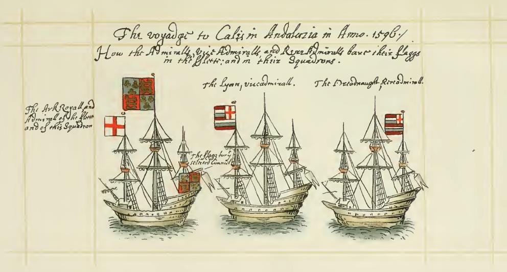
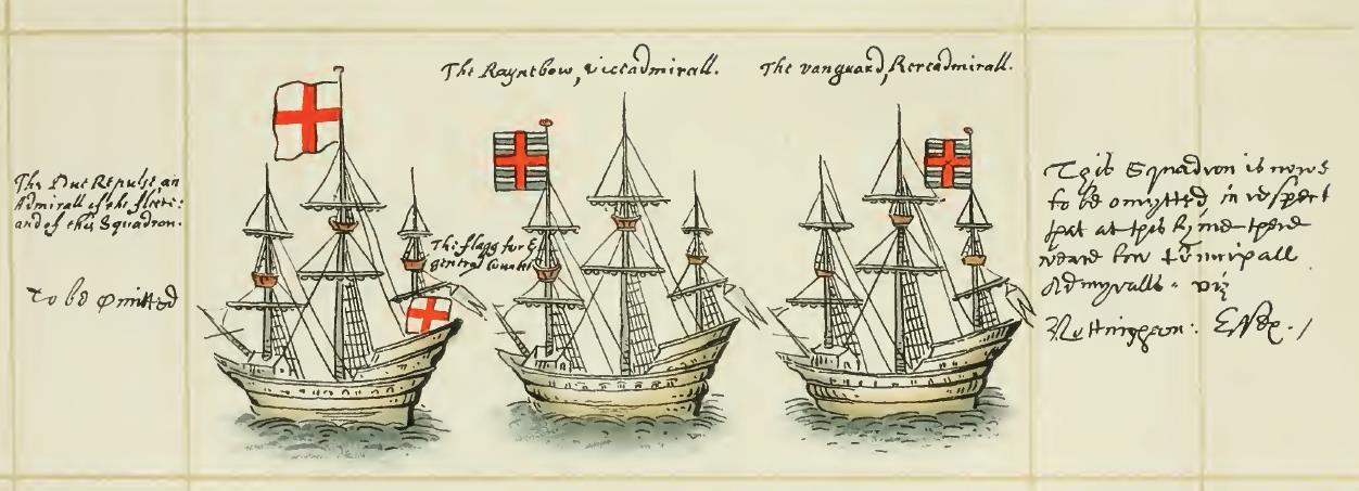
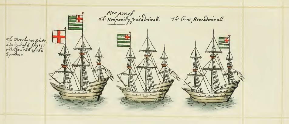
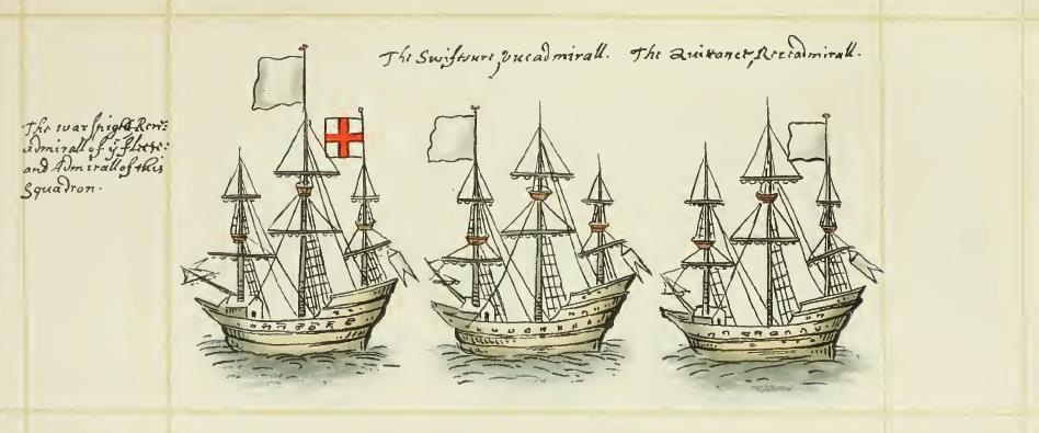
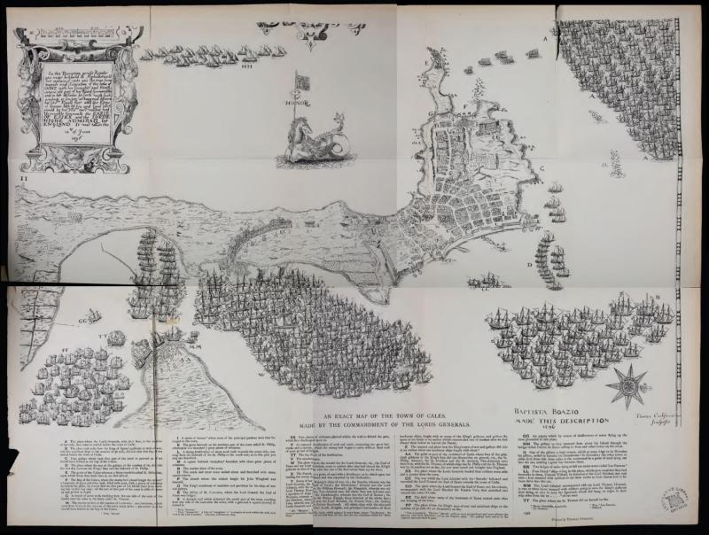
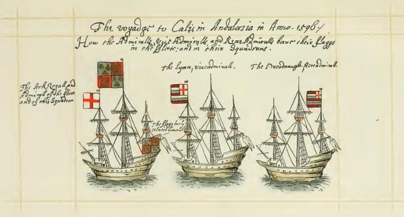
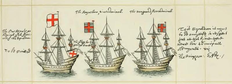
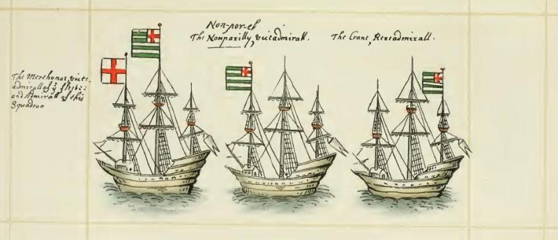
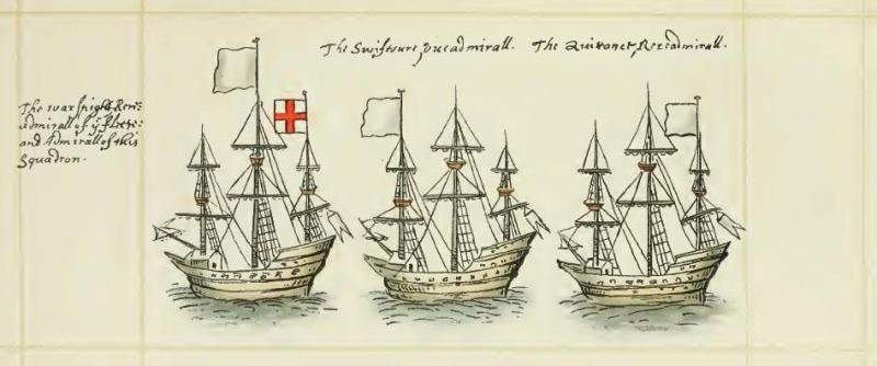
There are often times when i start out to peruse some newfound item that interested me and, due to my apparent inability to focus on the topic at hand, I wind up chasing some squirrel around to some totally different topic, and today is a case in point. Not really sure what I started off looking for, but I ended up perusing Laughton, J.K., W.G. Perrin, and C. Lloyd. 1902. The Naval Miscellany Vol. I. Publications of the Navy Records Society,v. 20, 40, 63, 92, 125, 146, 153. London: Printed for the Navy Records Society. https://archive.org/details/navalmiscellany01laug In there, I came across a rather fascinating article - The Voyage to Cadiz, 1596 The voyage to Calis in Andalusia, faithfully Related by Sir W. Slingisbye, employed in that service It describes the fleets, the political context, and so forth. Very interesting reading. I found, as well, the engravings to be most interesting, particularly the flags for each squadron. Lastly, for those with an interest in older cartography,
- 1 reply
-
- 6
-
-
- Royal Navy
- British History
- (and 1 more)
-
Spare Spars
trippwj replied to BANYAN's topic in Discussion for a Ship's Deck Furniture, Guns, boats and other Fittings
Pat - I agree with Allan (above) - no "establishment" type of listing for spare spars. I suspect that each class (and, for that matter, generation) of vessel had a common-practice set of spare spars, generally as generic as possible due to space constraints (that is, a spar that could be used as a top mast or top sail yard if needed, rather than individual spare spars for each). In the case of the Endeavour, it is likely that a few more may have been included since there were no convenient ports to put in to for repairs. You may find the best information in contemporary models or in logs and port records from the period. -
Wow, Denis - just wow! That metal work looks great, and really brings that mast to life.
-
According to the Royal Signals Museum: "In 1796, the Admiralty adopted a shutter-type machine, known as the ‘Murray Lettering Telegraph’ which was successfully used to communicate between London and Devonport. A year later the Army introduced the Radiated Telegraph System. The Radiated Telegraph System was more mobile system than the Murray Telegraph and remained in use throughout the Napoleonic wars." There is much more, but they also note the following: "Visual communications reached a peak during the second Boer war, and was the primary means of communications for forward control. Large and small flags, heliograph and oil lamps with shutters for night communications were all utilised. Skilled operators could signal between 8 and 12 words per minute. The climatic conditions were ideal for heliograph and the 10″ mirror could be seen for up to 100 miles. The Museum has equipment to demonstrate all these forms of communications." I suspect, though can't confirm, that the inter-service rivalry was such that neither would welcome a junior officer from the other with much warmth.
-
Off and running on this one, eh? Nice start - great to see you building again!
-
Well, that is a difficult query to accurately answer! I suppose that, given just the query itself, my answer would be "It Depends". Previous experience in wood and knowledge of the ship, as well as the era or time period of interest, can all drive the recommendation. In addition, the bias of the respondent can also alter the recommendations. What i offer here are a smattering of what, to me as a beginner, I have found most useful. It is not a complete list, and is heavy on some of the older "classics". The purist builder will find this list shocking - it ignores some of the more modern writers (such as Edward Tosti and David Antscherl) and is focussed on the beginner and the development of experertise and skill, rather than the master builder guides. Note also that most of my recommendations below are also readily available via various book sellers. So, here we go: Campbell, G.F. 1991. Neophyte Shipmodeller’s Jackstay. Model Expo Co. Davis, C.G. 1984. American Sailing Ships: Their Plans and History. New York: Dover Publications. ———. 1986. Ship Models: How to Build Them. New York: Dover Publications. ———. 1988. The Ship Model Builder’s Assistant. New York: Dover Publications. Dressel, D. 1988. Planking Techniques for Model Ship Builders. 1st ed. Blue Ridge Summit, PA: TAB Books. Johnson, G. 1996. Ship Model Building. 3. ed., and enlarged, 11. print. Centreville, Md: Cornell. Julier, K. 1993. The Period Ship Handbook. Annapolis: Naval Institute Press. ———. 1995. The Period Ship Handbook 2. Annapolis: Naval Institute Press. ———. 2003. Period Ship Kit Builder’s Manual. Annapolis, Md: Naval Institute Press. Lankford, B. 1988. Watercraft Modeler’s Handbook. Silver Spring, Md.: Nautical Research Guild. McCann, E.A. 1927. Ship Model Making: How to Make Worth-While Models of Decorative Ships. 1St Edition edition. The Norman W. Henly Publishing Co. ———. 1995. How to Make a Clipper Ship Model. New York: Dover Publications. Pariser, Daniel, ed. 2009. Ship Modeler’s Shop Notes, II. Cuba, NY: Nautical Research Guild, Inc. Underhill, H.A. 1958. Plank-on-Frame Models and Scale Masting and Rigging. 1: Scale Hull Construction. Glasgow: Brown, Son and Ferguson. Underhill, H.A. 1979. Masting and Rigging: The Clipper Ship [and] Ocean Carrier. With Authentic Plans, Working Drawings and Details of the 19th and 20th Century Sailing Ship. Glasgow: Brown and Ferguson. Underhill, H.A. 1985. Plank-on-Frame Models and Scale Masting and Rigging. 2: Mastmaking and Rigging, Sailing Models and Power Craft Hulls. Glasgow: Brown, Son and Ferguson.
-
Seeking information on determining load waterline
trippwj replied to trippwj's topic in Nautical/Naval History
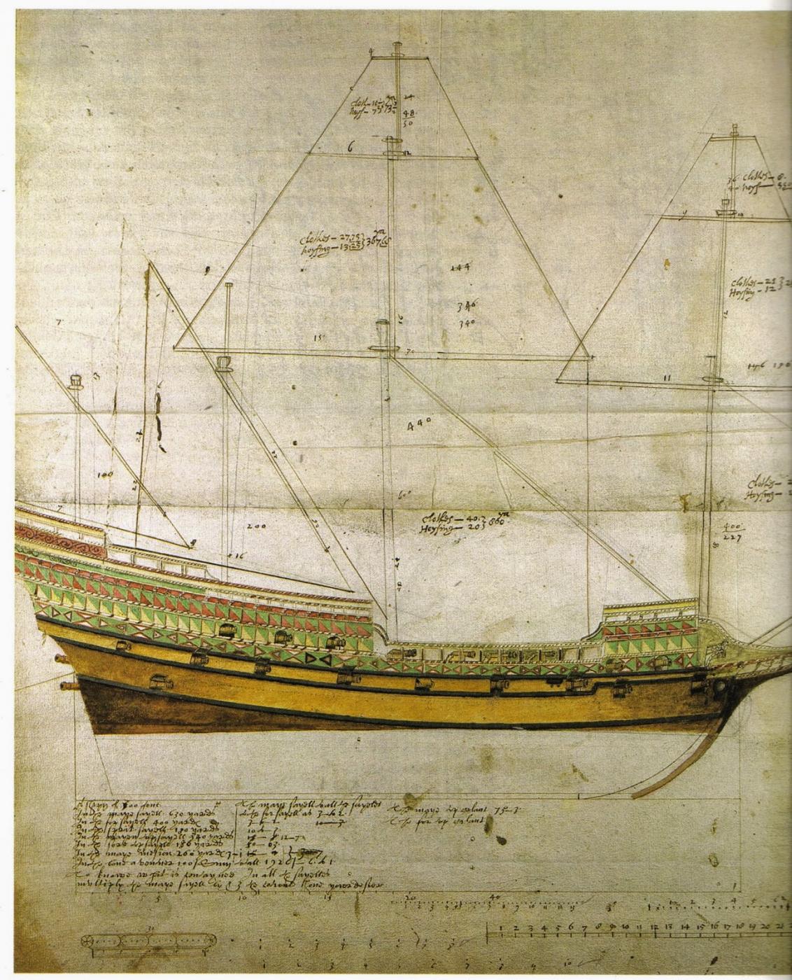
Perhaps lost in the past several pages of debate and discussion is the original purpose of my study – how and when did that simple line (Load Water Line) become a pre-determined height for inclusion on the design plans for a ship? I am not sure there is a singular answer, or date, or individual. There are examples of the presence of the LWL on plans dating back to the times of Matthew Baker (see, for example, his famous drawing of the Revenge, showing the immersed portion of the hull, 16th century). There are also the pre-construction estimates by the Pett’s (cited earlier, I believe) which verified extremely well post-construction (circa 1630). HOWEVER, we also have noted designers/constructors such as Sutherland throwing out a waterline of an apparently arbitrary level, and then others (and I must apologize, for in preparing this quick post I neglected to note the reference for that – I will locate it and add to a latter posting as soon as I am able!) offering the use of the desired waterline as the base line for drawing a ships plan. An interesting approach, but begs the question of how to guarantee the ship, as fully equipped for service, actually swims at the desired depth? I am, perhaps, getting closer to a defensible position, yet not there yet. Finding the boundary between a true “design” waterline (that depth at which the fully equipped ship will float, identified during the design of the ship) versus the “desired” waterline (that depth at which the ship floats when adjustments in equipping, stores, ballast &c. are made such that the vessel floats at the level intended). OOOHHH! Two new definitions added – thoughts on that distinction? Many thanks -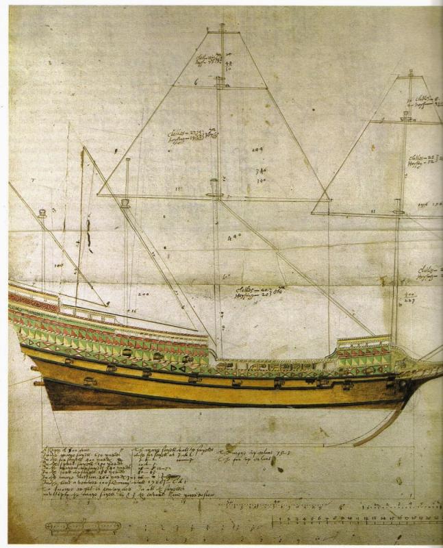
-
Dan - perhaps this site may be of some use to you: http://www.gwpda.org/naval/s0900000.htm. I have not yet been able to locate the original source document in on-line format, other than the bibliographic information: Admiralty, Great Britain. 1913. Handbook of Signalling. H.M. Stationery Office. 1. The Alphabetical Sign shows from which side the signs are to be read. 2. The Signs, as a general rule, are made by a Signalman facing the ships addressed; they are read from the right-hand side of the sending Signalman. 3. As it is often necessary to signal in opposite directions by the same semaphore, Signalmen must be careful to observe in which direction the Sender is facing, more especially when he is using hand flags, so that they can tell the side they must read the signs from their point of view. It should be noted that when the Alphabetical Sign is shown it is the left arm which is extended horizontally.
-
Sources for Rigging tables before Steel 1794 wanted
trippwj replied to archnav's topic in Masting, rigging and sails
You ask some good questions, Michael. In reference to the first portion: "Imagine the meeting or meetings where the new Establishment was agreed on sometime in 1745. Don't you think that sailors captains rigger, so called technical experts would have been called in. Ship's top hamper was constantly being repaired, modified, and experimented with. Look at the never ending discussions on this website about the finer points of Old Ironsides rig. So I think these guy showed up and said "here are some things we have been doing at sea over the last few years that improve performance".And they got them made official. Under that scenario you might reasonably find some of the changes of 1745 actually in use on ship prior to that time." According to Brian Lavery, for the previous Establishments, the dimensions had been decided upon through consultation with the Surveyor and senior shipwrights. In June 1745, the Admiralty took the lead when it decided to deal with the problem of ship sizes, and set up a committee to review proposals made by the Navy Board. The original purpose of the Establishments was to standardise the fleet, but because ships had been built and rebuilt at various times to varying established dimensions, there was little more standardisation than had been present before the 1706 Establishment came into being. The new Establishment of 1745 was intended to correct this situation, and at the same time solve the issues with British ships that had been the cause of complaint by sea officers for several years. The Establishments, in some ways, reflect the evolution and internal bureaucratic struggles within the navy. The earlier establishments were more like guidelines, and subject to individual interpretation. They reflected the conservative tendencies of the established shipwrights. The 1745 establishment attempted to require standardized design by also require the development of plans for each ship designed to the establishment, and the strengthening of the authority of the surveyor of the navy. In regards to the second part: "Everyone is fixated on the ratio of beam to mainmast. True enough and it changes over time. But the other spars changed in relation to the main mast as well. In particular the length of the topgallant yards in relation to the length of the other yard increased steadily over the years. You can see from my tables above the ratio of topgallant yard yo topsail yard went from .58 in 1719 to .69 in 1745.The ratio of the topsail yard to the main yard remained at .7 The ratio of the topgallant mast to the top mast remained the same as well at about .48-.49. The topgallants in 1745 were noticblely wider in proportion to thier depths and to the topsails in 1745 than in 1719. This had the effect of reducing the taper of the sail plan as it went up. I ma certainly not an engineer but it must have been improvements in hull stability and spar materials that allowed them to raise the center of effort." It may have reflected a gain in experience, but hardly a recognition of the importance of terms like "stability" and "center of effort". The Royal Navy was exceedingly slow to recognize the physics involved and incorporate those ideas into ship design - not until the late 18th and early 19th centuries did the Navy shipwrights begin to discuss these ideas, establishing the School of Naval Architecture in 1811 (and then closing it as a result of political infighting and changes in who was most influential) until the mid 1800's. There is much more that could be added concerning those issues, but not germane here - see my ongoing analysis here http://modelshipworld.com/index.php/topic/9892-seeking-information-on-determining-load-waterline/ "So the question is which Establishment do my self titled" inter-Establishment" ship look most like." That, my friend, is indeed a very good question. Look to the builder and captain, and their other ships of similar size, for the most likely answer. -
Sources for Rigging tables before Steel 1794 wanted
trippwj replied to archnav's topic in Masting, rigging and sails
Prior to adoption of the 1745 establishment, the most recent predecessor would be in use. If there were no changes to the masting rations in 1733 or 1743, then the 1719 establishment would be the most appropriate. I am not familiar enough with the 1733 and 1743 establishments so can't be much aid there. -
Sources for Rigging tables before Steel 1794 wanted
trippwj replied to archnav's topic in Masting, rigging and sails
The beam was used to calculate the size of the spars - the dimension of the spar would change with the beam, not as a proportionate change to the other vessel. For example, in the 1719 establishment, the length of the main mast for a 60 gun 4th rate was 2.34 times the beam. In the 1745 establishment it was 2.22 times the beam. All the other spars were then related to the main mast or, for the yards, the length of the gun deck. -
Sources for Rigging tables before Steel 1794 wanted
trippwj replied to archnav's topic in Masting, rigging and sails
I have never seen any of the establishments published in full, although Lees has tables from several in his work. The 1745 establishment, according to Lees, may be found in the Caird Library at the NMM. -
Sources for Rigging tables before Steel 1794 wanted
trippwj replied to archnav's topic in Masting, rigging and sails
Danny Vadas has provided a spreadsheet which will calculate the size for various lines based on the data in Lees for English ships of war 1625 to 1860. It may be downloaded here: http://modelshipworldforum.com/ship-model-masts-and-yards.php -
Sources for Rigging tables before Steel 1794 wanted
trippwj replied to archnav's topic in Masting, rigging and sails
I suppose, since Sutherland was mentioned above, I ought to include a snippet from him. This is from the 1717 version: Sutherland, W. 1717. Britain’s Glory: Or, Ship-Building Unvail’d, Being a General Director, for Building and Compleating the Said Machines. Tho. Norris. http://echo.mpiwg-berlin.mpg.de/ECHOdocuView?url=/permanent/shipbuilding/Suthe_Brita_01_1717/index.meta.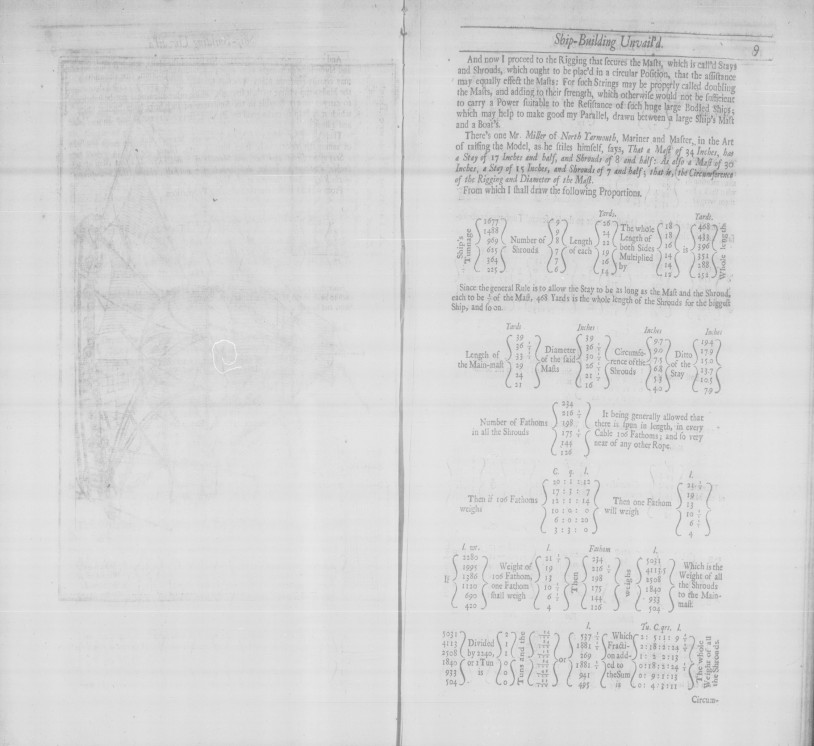
-
Sources for Rigging tables before Steel 1794 wanted
trippwj replied to archnav's topic in Masting, rigging and sails
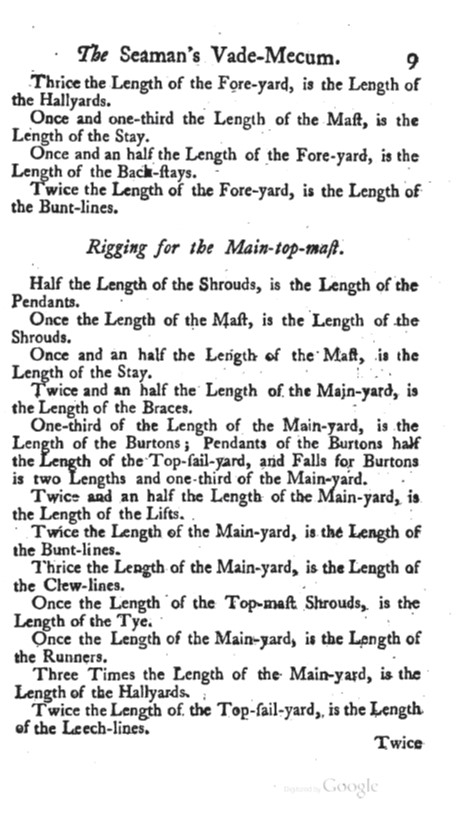
Unfortunately, I have not come across very many good tables on rigging thus far - that is the next in depth topic I am going to be pursuing. In the interim, here are a couple of thoughts and a resource of sorts. Rigging methods and ratios, much like ship building and naval architecture as a whole, developed slowly and incrementally, rarely undergoing periods of great change. While the methods of attaching specific lines to blocks or of manufacturing blocks may have evolved, along with the nuamnces of a mast or sail (such as the spritsail topmast, for example), the fundamentals (such as the thickness of a cable required to support a mast or yard) remained relatively constant until the advent of steel and iron cables. This matters, because Steel (1794, 1796) would reflect established practice for the period preceeding publication - which was likely in use during the mid-18th century. It may prove beneficial to compare Steel (1794) to Bond (1704) to see what may have changed, and likewise see how Mountaine (1761) fits into the gap. Bond, H. 1704. The Art of Apparelling and Fitting of Any Ship... http://echo.mpiwg-berlin.mpg.de/MPIWG:A09VZBVW. Mountaine, W. 1761. The Seaman’s Vade-Mecum and Defensive War by Sea. http://books.google.com/books?id=a8IzAQAAMAAJ. From Bond (1704, originally puclished 1663) From Steel (1794) From Mountaine - provides narrative based on size of the item to which a line is assigned.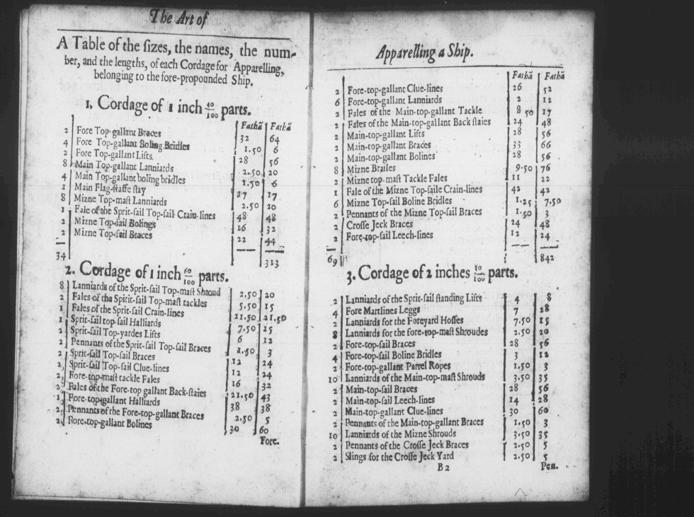


-
Belated Happy Birthday, Elijah. That should be a neat second build for you!
- 701 replies
-
- 4
-
-
- phantom
- model shipways
- (and 1 more)
-
American sailing warships with no plans or records
trippwj replied to CharlieZardoz's topic in Nautical/Naval History
This discussion is quite interesting, although sometimes it moves between topics so rapidly that additional research and input becomes lost in the flow. I think that the over-rigging of these frigates and sloops was a long term ongoing concern, both for the young American Navy and the mature, bureaucratic British and French Navies. Sticking solely with the American Navy, one need look no further than the debates surrounding the construction of the original 6 frigates. The Secretary of War ORDERED the assigned Superintendents (future Captain of the assigned ship) Barry, Talbot & Truxton to meet with Humphreys and provide a report with the recommended dimensions for the rigging. War office Sept 30 1795 The Secretary of War requests the Captains Barry, Talbot & Truxton now at Philadelphia with Mr. Humphreys the constructor, to consult together on the proper dimensions of the masts and spars for the frigates, and report their opinion under their hands in such form that the same may be transmitted to all the constructors and superintendents on their guide. Timothy Pickering This was partially in response to a letter from Truxton enclosing a copy of both his approach to masting and that published by Steel (see attached appendix 6 from Truxton - this copy appears to have been that of Fox). 1794 Masts Article_Truxtun.pdf Also see this letter Truxton to Pickering, then forwarded by Pickering to all the Captains, concerning same. 1795-3-25 TP circular to Captains_NBB19 3pgs.pdf The end result was a capitulation - each Captain, in consultation with the constructor for his frigate, was to determine the best method and dimensions and then send them to the War Department. 1796-1-25 TP to JH ST_Mast as wish circular letter NBS03 NBD01 1 page.pdf- 401 replies
-
- 3
-
-
- John Adams
- Alliance
- (and 3 more)
-
American sailing warships with no plans or records
trippwj replied to CharlieZardoz's topic in Nautical/Naval History
According to the description, this was while in ordinary in Norfolk, VA. See http://www.history.navy.mil/our-collections/photography/numerical-list-of-images/nhhc-series/nh-series/NH-108000/NH-108535.html- 401 replies
-
- 2
-
-
- John Adams
- Alliance
- (and 3 more)
-
American sailing warships with no plans or records
trippwj replied to CharlieZardoz's topic in Nautical/Naval History
I would, in reference to early 19th century US Naval ship design, be careful about using terms like "standard issue" and "standard design". The US Navy was still far from a bureaucratic beast at the time, and while there was a Naval Constructor (Fox, Doughty, Samuel Humphreys and Henry Eckford during the period in question), it was not until much later that the Chief Naval Constructor really achieved some solid measure of authority. Each of these designers, responsible for various classes of ships built at the time, had very different design approaches, and the vessels would show the individual bias of the designer. HOWEVER, the captain also had a great deal of leeway to make cosmetic adjustments within the approved construction budget, so there may be some trends toward commonality, not in design so much as in the taste of the skipper.- 401 replies
-
- 2
-
-
- John Adams
- Alliance
- (and 3 more)