trippwj
-
Posts
3,156 -
Joined
-
Last visited
Content Type
Profiles
Forums
Gallery
Events
Everything posted by trippwj
-
It may, perchance, be worth a visit to the Mariner's Mirror for some information on past practice. For example, we have a collection of eye witness sketches and detailed descriptions of the vessels at the Battle of the Nile available here: Paul, L. 1914. An Artist’s Notes at the Battle of the Nile. The Mariner’s Mirror 4, no. 8: 266–273. http://dx.doi.org/10.1080/00253359.1914.10654827. We may also glean a bit of information from the Carpenter's notes concerning supplies &c. for the Victory discussed by one of the eminent marine historians (a former curator for the Victory) available here: Goodwin, P.G. 2013. The Application and Scheme of Paintworks in British Men-of-War in the Late Eighteenth and Early Nineteenth Centuries. The Mariner’s Mirror 99, no. 3: 287–300. http://dx.doi.org/10.1080/00253359.2013.815993. Here are a couple of tidbits from the latter: The Victory’s carpenter on 18 August 1805 recorded: ‘To whitewashing the Tiers, Wings Cock-pits Store-roomes (sic) Lower & Middle Decks – Lime 12 Bushels Glue 12 Pounds’. Acting on this information a request was submitted to the VATC to change the internal colour along the ship’s side of those gun decks from buff yellow to white. It appears that the original reasons for paying up the Victory’s internal sides with whitewash were as follows: 1 To brighten up and improve light levels to the interior of the gun decks where the majority of the seamen and marines lived 2 To kill off potential bacteria (a natural property of whitewash) for much the same purpose as the common land practice at that time of whitewashing back yards and outhouses etc. of houses. 3 Whitewash, being a cheap commodity could be applied regularly. Research revealed that the glue was fish glue, which acted as a binding agent. The whitewash mix would have comprised slaked lime and sea salt, boiled with water, added to which was the fish glue. The carpenter’s entry dated 14 September reads: To painting the ships side after caulking, the Gunroom and Officers Apartments under the Awning and Quarter deck Waist &c. after Refitting and the paint and materials consumed for the above entry listed in the margin are given as: Yellow – 350 lbs; Black – 150 lbs; White – 450 lbs.; Oil – 47 gallons; Brushes – 20 in No. It should be noted that the oil referred to is linseed oil, which is commonly used in paint as a binding and adhesive agent. These are the relevant stores supplied to Victory at Portsmouth on 31 August 1805: 1. White – 120 lb 2. Yellow – 34 lb 3. Black Varnish – 66 gallons 4. Glue – 12 lb 5. Lime – 8 bushels 6. Whitewash brushes – 6 Then on 2 September 1805: 1. Yellow – 350 lb 2. Black – 150 lb 3. White – 150 lb 4. Oil. – 47 gallons 5. White – 66 lb 6. Black – 13 lb 7. Yellow – 78 lb 8. Verdigris (sic) – 5 lb 9. Prussian Blue – 1 lb Then on 6 September 1805: 1. White – 86 lb 2. Yellow – 234 lb 3. Oil. – 2 1/2 gallons 4. Black Varnish – 66 gallons. lb.32 Note that no red is listed. Now, I freely concede that the information which I have offered is limited both in time and space (time - late 18th early 19th century, and space - Royal Navy. Sort of a warp in the space-time continuum reflective of the gravity of the Nelson era, eh?). HOWEVER - Goodwin brings in more perspective on earlier period (mainly, again, British navy, although there is a bit on the French). Practice in the US is likewise available, though for a bit more work. I recommend, for example, the information on stores in Smith, P.C.F. 1974. The Frigate Essex Papers: Building the Salem Frigate, 1798-1799. Salem [Mass.]: Peabody Museum of Salem.
- 20 replies
-
- 10
-

-

Seeking information on determining load waterline
trippwj replied to trippwj's topic in Nautical/Naval History
Indeed! As "anonymous" pointed out (transcription courtesy of R. Barker) - 61. The height of the ship above water must be in proportion unto that part of the ship under water &c the height of the ship in the mid-ship must not exceed the depth under water & the height of the stern must not exceed the height of the depth twice & the height of the forecastle must not exceed the depth once & 1/3. Not particularly scientific - more a rule of thumb based on existing practice and experience? -
Seeking information on determining load waterline
trippwj replied to trippwj's topic in Nautical/Naval History
Bruce - I have seen an additional 2 or 3 treatisers whom mention this method, though none seem to actually have used it. The challenge becomes one of actual scale equivalence - scaling length, breadth and depth is fairly easy. Scaling density (specific gravity) and weight is not quite so linear. The weight doesn't scale directly proportional (since the density does not change) when the physical dimensions are scaled. It may be useful to accurately model the below water hull form and then measure the displacement when it is submerged (irregardless of the mass involved), then scale this volume to seawater at a 1:1 scale. Unfortunately, I suspect that the level of accuracy (how small an amount of volume can you measure) plays a role - even a small amount missed at 1:48 scale can become much more important at 1:1 scale. -
The subsciption frigate New York and other details
trippwj replied to CharlieZardoz's topic in Nautical/Naval History
Good start, Charlie! Love the seal story and assemblage - quite the variety in style and interpretation! I guess a good place to start would be to see if there be records such as there were for the Salem Frigate (the Essex) maintained by the subscribers. Any info out there on the Peck and Carpenter ship yard? I have started some light searching at the Papers of the War Department web site with no success yet, but the search engine there is not particularly robust (difficult to refine searches very well unless you know the writer and recipient precisely).- 51 replies
-
- 3
-
-
- frigate
- subscription
- (and 1 more)
-
Wonderful subject, and a wonderfully informative log - mind if I lurk here and admire your work?
- 641 replies
-
- 2
-
-
- greenwich hospital
- barge
- (and 1 more)
-
Seeking information on determining load waterline
trippwj replied to trippwj's topic in Nautical/Naval History
Hello, John - As I am regrettably only bilinqual (English and Yankee), any aid in understanding the French (or Dutch, Spanish, Italian etc. ) contemporary reference works would be greatly appreciated! -
Seeking information on determining load waterline
trippwj replied to trippwj's topic in Nautical/Naval History
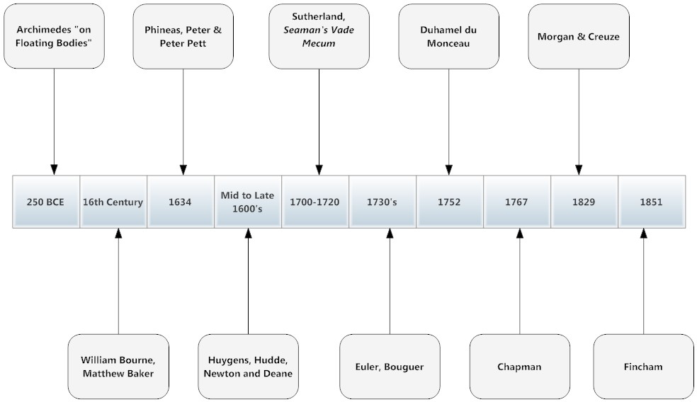
Still working on how best to visualize the parallel yet disjointed development of the science and implementation into shipbuilding. Not sure this really tells the story - I am thinking that it may be better graphically to keep the science on one side of the timeline and the application on the other. Your thoughts?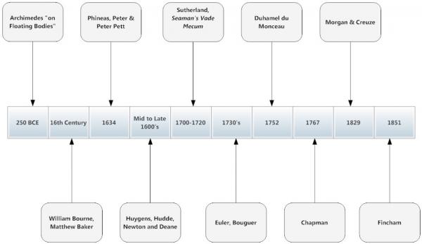
-
Seeking information on determining load waterline
trippwj replied to trippwj's topic in Nautical/Naval History
Meaning no insult to Sir Anthony Deane, I wanted to take a moment to elaborate somewhat on earlier methods of determining the burthen of a ship. William Bourne published a rather difficult to read (due to the typeface, see earlier post in this thread) treatise called A Booke Called the Treasure for Traveilers : Devided into Five Bookes or Partes, Contaynyng Very Necessary Matters, for All Sortes of Travailers, Eyther by Sea or by Lande. Richard Barker has provided a transcription (and modernized the language) of the sections related to measuring ships. His transcription may be found here: http://home.clara.net/rabarker/Bourne2m.htm Bourne describes two methods - in the first, the vessel is grounded, and the physical dimensions taken. His alternative method is described as "an easier way than rehearsed above, by the Art Statical, to know the true weight of any ship, with all her lading, and all the rest of her furniture". Here is a very brief excerpt - I encourage you to read the full description. And now I caused the mould to be made for every foot, but a quarter of an inch, so that for the 50 feet long the mould was made 12 inches and a half, and for the 20 feet broad, but 5 inches, and for the 12 inches deep, but 3 inches. And that being filled with water, the water being weighed, did contain in weight 3 pounds and 2 of 73 parts [sic: probably derived from the ratio of Troy to Avoirdupois pounds as 60:73. 1/30 Troy pound, 2/5 of a Troy ounce, is 0.438 ounces Avoirdupois. Bourne presumably experimented with a set of Troy weights] of a pound, and that is scant half an ounce, and the true contents of the weight of the water. And then from that you see that the proportion of the length of the mould, is but 12 inches, and one of 2 parts; that is, but the 48[th] part of the length of the ship. Therefore multiply it in this manner 48 times 48 and that makes 2304 and then multiply it by 48 again, and then it makes 110592. Wherefore now multiply 110592 by the weight of the water, that is to say 110592 times 3 and 2 of 73 parts. And that makes 334620, so that you may conclude that the ship weighs 334640 pounds. And now to know how many tons the ship weighs, by dividing by 2240 as declared above, and so further as rehearsed above. And furthermore, you may cause in the proportion of the mould of lead or tin, to be certain parallel lines, to be made but a quarter of an inch asunder, as many as you like, and then you may know by those lines what weight the ship is of, when she is not laden. And also, if you wish, you may know how many tons more in weight, will load the ship, as often as you do know how many feet or inches the ship lacks from her load mark. -
Seeking information on determining load waterline
trippwj replied to trippwj's topic in Nautical/Naval History
The Royal School of Naval Architects When considering the British implementation of formal study, there is a clear and (in my opinion) destructive conflict between the “traditional” (that is, shipwrights who came up the old way with no formal education), the “empirical” (that is, the Captain of a Ship knows more than any civilian possibly could) and the “scientific” (the incorporation of mathematical and scientific methods to understand resistance, stability and so on) approaches to Naval Architecture. At different times, each was dominant. The rise of the Scientific method coincided with the leadership of Sir Robert Seppings as Surveyor of the Navy (1813 – 1832), and the decline (for lack of a better word) into strict Military rule with the resignation of Seppings and the appointment of William Symonds. Symonds' "empirical" school of shipbuilding came into conflict both with the "scientific" school led by the new class of professional naval architects and the first School of Naval Architecture, and the "traditional" school led by Master Shipwrights from the Royal Dockyards. The following is an extract from Anonymous. 1847. Review of the Course Pursued by the Shipbuilding Department of the Admiralty between the Years 1832 and 1847, Etc. [With Diagrams.]. R. White Stevens. https://books.google.com/books?id=GrNWAAAAcAAJ. On reviewing the history of the Civil department of the Navy, we find by a report to the House of Commons, 16 July, 1806, very important observations relative to the then existing state of the dock yards, and a plan proposed for training up for the public service an educated class of persons who “should form the plans of our ships of war, consistently with scientific principles,”—the commissioners stating that a want of proper foresight and due consideration in our shipbuilders must finally lead to much danger to the country. They further state, in regard to the Shipwrights’ apprentices, “that they rise to the direction of the construction of ships, on which the safety of the empire depends, without any care being taken to give them the least instruction in the science of Naval Architecture.“ This led, in 1811, to the establishment of a School of Naval Architecture at Portsmouth, previously ratified by the King in Council, in 1809, for introducing properly qualified men into the service. Notable members from the School of Naval Architects (1811 to 1832) include: Reverend James Inman James Peake William Morgan Augustin Francis Bullock Creuze -
Seeking information on determining load waterline
trippwj replied to trippwj's topic in Nautical/Naval History
Mark - The French were, in some ways, far ahead of the British in the science of ship design. For example, it was at the request of the Admiralty that Pierre Bouguer expanded on the use of trapezoids to determine tunnage and displacement. Regrettably, after a period of embracing the mathematical design (vice geometric - parabolas, arcs etc), there was a change in regime which altered the acceptance of science for a time, but not nearly as serious a disruption as the British. For some interesting discussion (not necessarily easy to pull out, since it is part of a broader narrative on Ships and Science) see Ferreiro, L. 2007. Ships and Science the Birth of Naval Architecture in the Scientific Revolution, 1600-1800. Cambridge, Mass.: MIT Press. http://search.ebscohost.com/login.aspx?direct=true&scope=site&db=nlebk&db=nlabk&AN=173439. Good point, Joel, though not quite accurate - the French were successful at making the transition. See Ferreiro, L. 1998. Organizational Trust in Naval Ship Design Bureaus France, Great Britain, and the United States. Acquisition Review Quarterly. https://www.academia.edu/1573277/FRANCE_GREAT_BRITAIN_AND_THE_UNITED_STATES. for a brief overview. (extract below): Pride of place goes to France for forming the first professional corps of naval constructors. The Génie Maritime, as it was known (génie means both engineer and genius), was formed in 1765, and was marked by a rigid system of application into the corps, including the training in shipyards and education in engineering, and a formal system of advancement based on technical merit. The Génie Maritime became the model for the naval construction corps of many countries, including Spain, the Netherlands, Japan, and Britain. The constructors of the Génie Maritime operated autonomously, each in their own shipyards, until 1895, when ship design was centralized into one bureau. -
Seeking information on determining load waterline
trippwj replied to trippwj's topic in Nautical/Naval History
Joel - I somehow suspect that you're probably right, at least into the mid-19th century. -
Seeking information on determining load waterline
trippwj replied to trippwj's topic in Nautical/Naval History
Weight estimates have been available for many a year. For example, Sutherland (Sutherland, W. 1711. The Ship-Builders Assistant : Or, Some Essays towards Compleating the Art of Marine Architecture. London: printed for Mount, Bell, and Smith. http://echo.mpiwg-berlin.mpg.de/MPIWG:12RWTM5U)provides several examples of weight for various types of ships. Likewise, Mungo Murray (Murray, M. 1754. A Treatise on Ship-Building and Navigation. In Three Parts, Wherein the Theory, Practice, and Application of All the Necessary Instruments Are Perspicuously Handled. With the Construction and Use of a New Invented Shipwright’s Sector ... Also Tables of the Sun’s Declination, of Meridional Parts ... To Which Is Added by Way of Appendix, an English Abridgment of Another Treatise on Naval Architecture, Lately Published at Paris by M. Duhamel. London, Printed for D. Henry and R. Cave, for the author. https://archive.org/details/treatiseonshipbu00murr) provides more detail on weights (both above and immersed). There are many more dating from about the middle of the 18th century such as Rees, Morgan and Creuze and so on. The weight calculations, however accurate, were present. In the case of Murray, he calculates the weight of the hull plus furniture (masts, blocks, pumps, cables, anchors) for the Renomee (Frigate of 30 guns) to be about 52% of the total weight for the ship when fully provisioned and crewed (see summary table below). Of these components, the next largest weight component after the hull and furniture is provisions (not a great deal of freedom to not load these), followed by the ballast (the only true variable that the Captain has some control over, albeit not very much!). The open question, of course, remains the same - did the shipwright of old actually use the information to determine the load water line? I have some theories, but that would be getting ahead of myself. Keep the suggestions coming - each drives me back to the source documents to see what they contain, and I find new stuff each time!
-
Once the port is framed the rest of the way (bottom cill, side timbers) that will be pretty centered as is. It looks high now because the port opening is wider and taller than the finished opening.
-
Seeking information on determining load waterline
trippwj replied to trippwj's topic in Nautical/Naval History
Just a brief update to reassure you all that I have not forgotten nor forsaking this undertaking! While I am not close to being able to draw any definitive conclusions, I am still learning and, as time allows, gathering new information. I recently came across an interesting reference - McGee, D. 1998. The Amsler Integrator and the Burden of Calculation. Material Culture Review / Revue de La Culture Matérielle 48, no. 1 (June 6). http://journals.hil.unb.ca/index.php/MCR/article/view/17794. The author provides some interesting perspective on how the Amsler Integrator was instrumental in ship builders (and Naval Architects) finally began to actually calculate the immersed volumes to obtain more accurate volumetric data for not only displacement but also stability purposes. Stability calculations (and, by extension, displacement curves and calculations) were rarely done for Naval (and almost never for merchant) vessels due to the immense number of calculations necessary to produce them, until the introduction of the Amsler Integrator. From McGee: Arriving at the data for each section was a thing of incredible simplicity. The track for the instrument was laid down on the drawings and the instrument placed in the track. The pointer was placed on the drawing and readings were taken from the vernier scales attached to the cogwheels. The pointer was then used to trace the outlines of the irregular curve or section to be measured. The rollers turned the cogs, and new readings were taken from the scales. The initial readings were subtracted from the new readings. The results were then multiplied by a constant provided by the manufacturer. And that is all there was to it. In a few minutes the operator could know the area and moment of any section in the body, sheer, or half-breadth plans. The operation then had to repeated for the other sections. The resulting tables of areas and moments could then be combined by mathematical means to arrive at the location of the centre of buoyancy of the vessel in question. So – what does this mean for those Load Water Lines (and the swimming line, for that matter)? Were they “real”, determined pre-build? Were they added after launch and fitting out? Were they conjectural – representing the desired outcome, subject to the actual results when the ship was built??? -
Even with a waterway, there would be a camber to the deck beams (and then to the planks). At this scale, it would be slight but a bevel on the lower edge of bulwark planks would accomodate it (take a little off the inner edge at the bottom to align with deck camber). On the other hand, the sheer (fore and aft) would be more challenging to accomodate.
-
When you click the down arrow on the left another window should shiw up with pdf or jpg as options and a small square block to click at the bottom agreeing to the terms. If the window doesn't show you may have a setting in your briwser blocking it.
-
Wonderful resource - THANK YOU!!! This is one of the classics, frequently referenced. There is a modern reproduction of many of the plans available as well, but the original is always a better resource.
-
Don - Make sure the pdf button is clicked, and the check box at the bottom of the window that pops up.
-
The sill is actually the lower framing piece (horizontal). The planking should be nearly to the edge on all sides. The port lid would fit within the opening, with the outer surface flush with the planking. The stops are there because the port is in the opening, not over it. Goodwin has a couple of drawings in his English Man of War (around page 288). Will edit to include full citation when I can. Here's another analogy to consider: look at the door frame on older doors - they all have a "jamb" to stop the inward travel.
-
Not so sure about how important the time frame is - Steel (1763-1803) and Fincham (1784-1859) were both writing about the same era, and the same paradigm related to construction. Allan has provided a much better sketch of the structure - not really surprising it is not shown on many contemporary models - at 1:48, the 2" height would be nearly impossible to accurately portray (translates to something like 0.04" of height within the gunport.) I also erred in my sketch - based on Fincham there is no stop on the underside of the lintel (serves no useful purpose there).
-
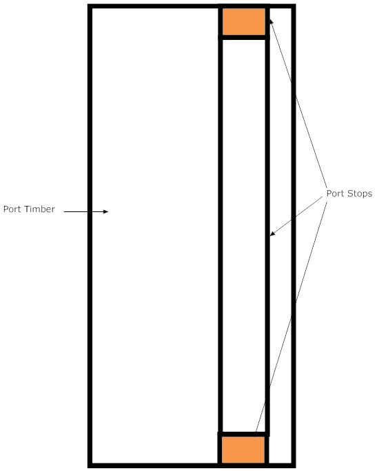
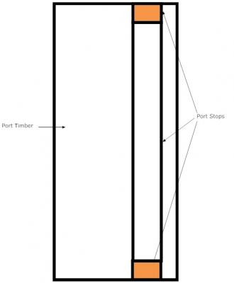
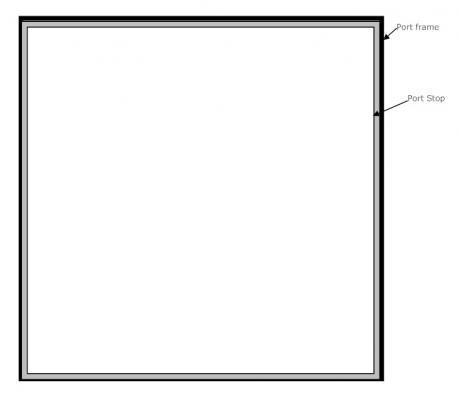
OK, then - here is a VERY poor attempt to show how the port stop fits relative to the port framing. This first view is from the outside looking in. Here we are looking from the side at the port in cross section. Note the stop is set back some distance from the face of the port, allowing the lining to fit within the opening. CAVEAT - these are not in scale of any sort.
-
That does appear to be the definitive definition, so to speak. It sounds, to my admittedly frail mind, that one can envision the stops as analogous to pieces of 2 x 4 laid along the sides and bottom of a window to which (in older homes, at least) the storm windows were fitted - it kept them from projecting too far inside, ensuring the more or less flush fit with the exterior walls. In the case of the port lids, it also reduced the risk of the port lid being forced too far into the port by exterior action (such as waves and water pressure). I am a very poor sketch artist, but will try and come up with something to show the concept.
-
David Steele, as famous as his works are, is not (never was, as best can be determined) a shipbuilder nor naval architect, but rather an extremely well connected (within the Admiralty) book publisher. One of life's great mysteries remains - who actually wrote his Naval Architecture? A contemporary source, which is more authoritative only because the author was both a shipbuilder and a naval architect, is Fincham, J. 1825. An Introductory Outline of the Practice of Ship-Building, &c. &c. Directions for the Repairs of Ships. Portsea England. Sold by W. Woodward. http://catalog.hathitrust.org/Record/009723747(note there is also an 1821 edition available: Fincham, J. 1821. An Introductory Outline of the Practice of Ship-Building, &c. &c. William Woodward, https://books.google.com/books?id=pKZWAAAAcAAJ ) From his 1825 edition, I have extracted the following (sorry, but I have not yet been able to obtain all the figures, but I keep trying!) HALF-PORT (Page 200): shifting shutters fixed in the stops of those ports, which have no hanging lids. Those to the quarter-deck and forecastle ports are in general in one, and made of two thicknesses of slit deals, and to the ports for the long guns have holes in them for the gun to run out; and those to the upper deck, In two parts called buckler half-ports; for long guns, the lower part is to the center of the gun, when run out and levelled, as they have a hole in them that fits close round the guns ; and to carronades, to the underside of the gun, if not too low, that they may be fixed over them. The lower piece of these half-ports is of fir, and in one piece, to fill up the stops; with a rabbet taken out of its upper edge, to receive the upper part, and with two strengthening bolts driven up and down through it. This piece is in general hung with hinges at the lower part, and kept in its place by sliding bolts. The upper part is made commonly of whole and slit deal, the whole deal up and down, and the slit deal, to cross it, fore and aft. PORT (Page 224): the holes or embrasures in the sides of ships of war, for pointing the guns through, on the different decks or batteries. The ports are formed on the sides by the timbers of the frame*, and on the upper and lower parts by pieces lying after the sheer, called port sills (Fig. 12 and 15); they are distinguished by the upper (m) and lower (n) port sills; the upper is tailed into the timber, and the lower billed. * The timbers that form the sides of the ports are called port timbers, and in general have an excess of siding over the other timbers. PORT HOOKS (Page 225): iron hooks for fixing the port hinge upon, and upon which the port-lid revolves. One arm of the hook is driven through the side, at a proper height above the port, and is clenched on the inside. PORT LIDS (Page 225): lids or shutters fixed to the middle and gun decks of ships of the line. They are made of fir, in two thicknesses; the inner thickness is called the lining, and is placed with the range of fibre up and down, and of about 2 inches in thickness, with its inner part bedding or faying close to the back stops. The outer thickness, called the outside stuff, lies fore and aft, so as to cross the lining, and is of a substance sufficient to be well with the outer part of the outside planking, at the thinnest part. The lining is fastened to the outside stuff by nails, about 2 1/2 inches apart. These lids are hung with two hinges, which have in their lower end one shackle in each, outside, for the port ropes, and one in each, inside, for the port fastening. These shackles in general forelock. The hinges are fastened, in addition to the shackles, which form part of the fastening, with one saucer-headed bolt, as close up to the upper part as to be just below the upper stop, which is driven on the inside and forelocked on the out; and one or two saucer-headed bolts in each breadth of outside stuff is driven from the outside, and clenched upon the lining. In the port lid is cut a scuttle, to be opened for air when (he lid is shut in; and one illuminator is fixed in the lid, to give light, when the badness of the weather compels the scuttle to be shut in. The port lids are made to fit very close to the back stops, but to come out and shut in easy. After the ports are eased in, which is not done, for the last time, till all the guns and stores are on board, the back stops are lined over with fearnaught or kersey; and likewise the back stops of the scuttle. PORT STOPS (Page 226): are the ends and edges of the planks left round the ports, from 1 1/2 to 2 ¼ inches from the sides of the timbers and upper and lower parts of the sills, to receive the port lids and the half-ports.
-
Those are 3 wonderful gifts - please share your opinion on the book in the book review section after you get a chance to look through it (I am interested in whether I should add it to my collection).
- 701 replies
-
- 3
-
-
- phantom
- model shipways
- (and 1 more)