
HOLIDAY DONATION DRIVE - SUPPORT MSW - DO YOUR PART TO KEEP THIS GREAT FORUM GOING! (Only 24 donations so far out of 49,000 members - C'mon guys!)
×

Jeff-E
-
Posts
699 -
Joined
-
Last visited
Content Type
Profiles
Forums
Gallery
Events
Everything posted by Jeff-E
-
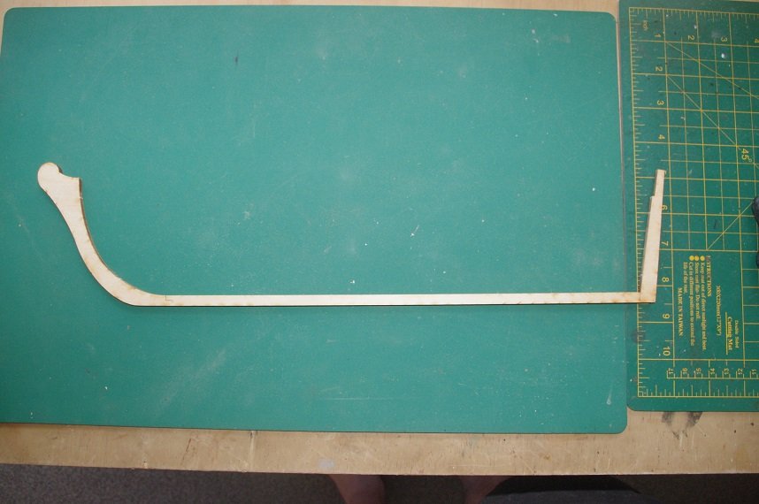
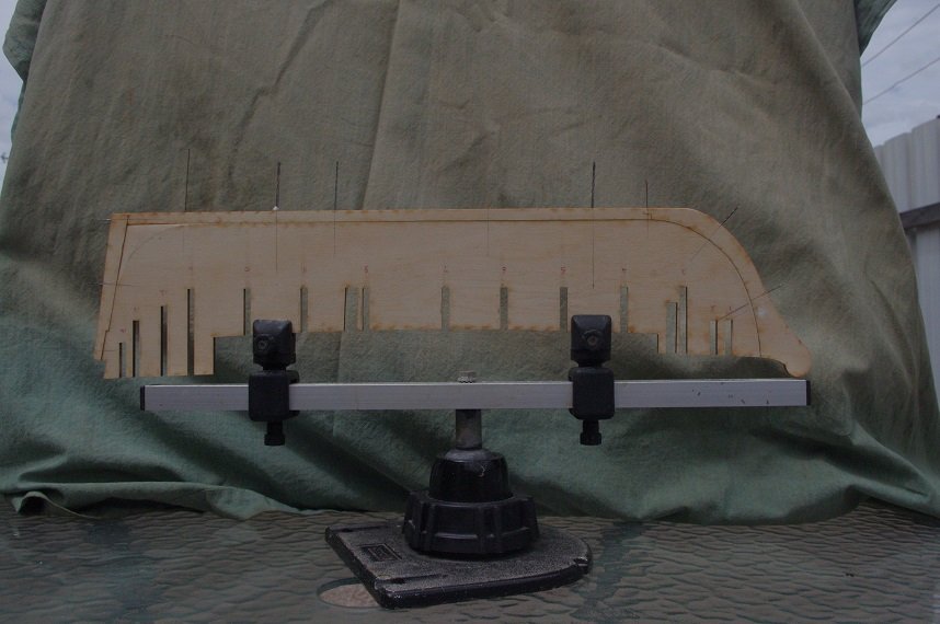
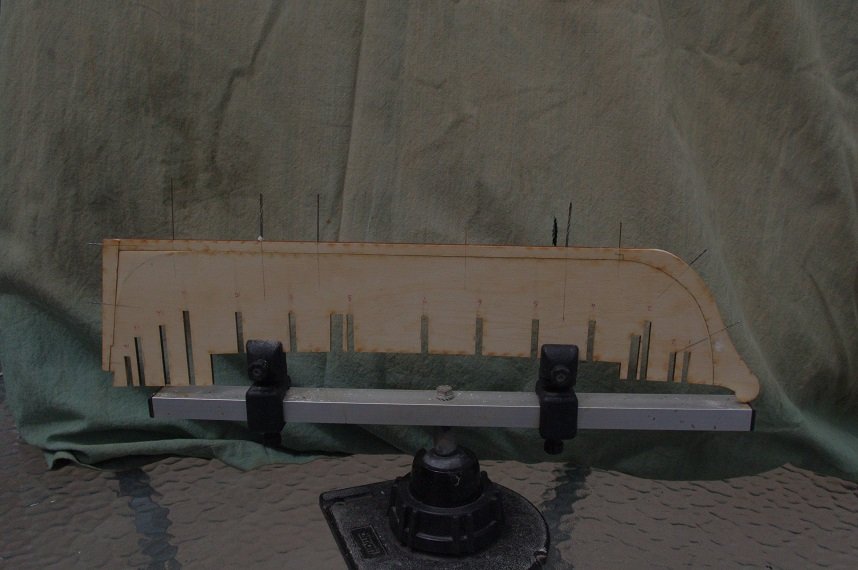
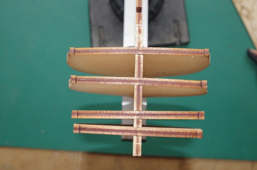
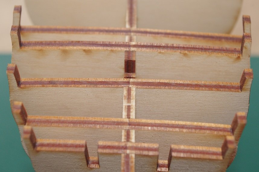
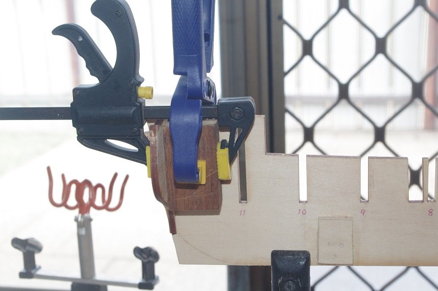
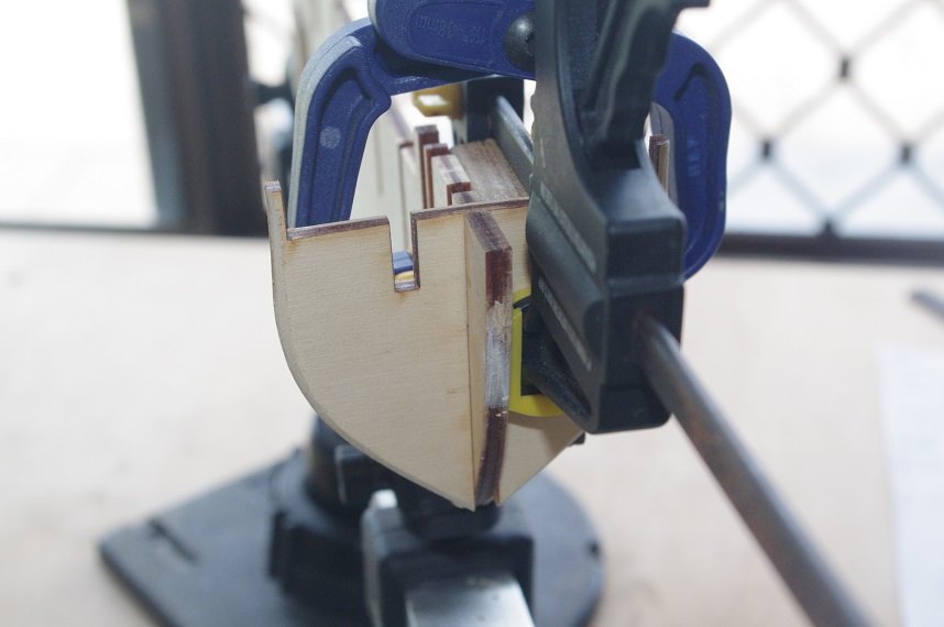
Thanks Keith and welcome. The keel, stempost and sternpost were cut from the ply sheet, I left the tabs connecting them together as it made it easier to clamp the whole assembly to the false keel while the dowel and mounting holes were drilled. Once that was done the support blocks for the mounts were glued on. They were given a slight chamfer so as not to interfere with the lower planks. As mentioned before some of the slots in the false keel and bulkheads needed to be filed out so that the bulkheads could sit square with the false keel without putting any strain on it. This was done and the ones that need a shim to allow them to sit level with the top of the false keel was also completed. Then the first two bulkheads were glued on. I am gluing the bulkheads starting at the bow and the stern and working towards the centre because of the small gaps between them in these areas so that I can clamp blocks to the bulkhead and keel to keep them square. Thanks for looking and the likes. All comments welcome.
-
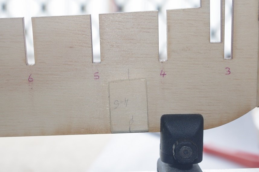
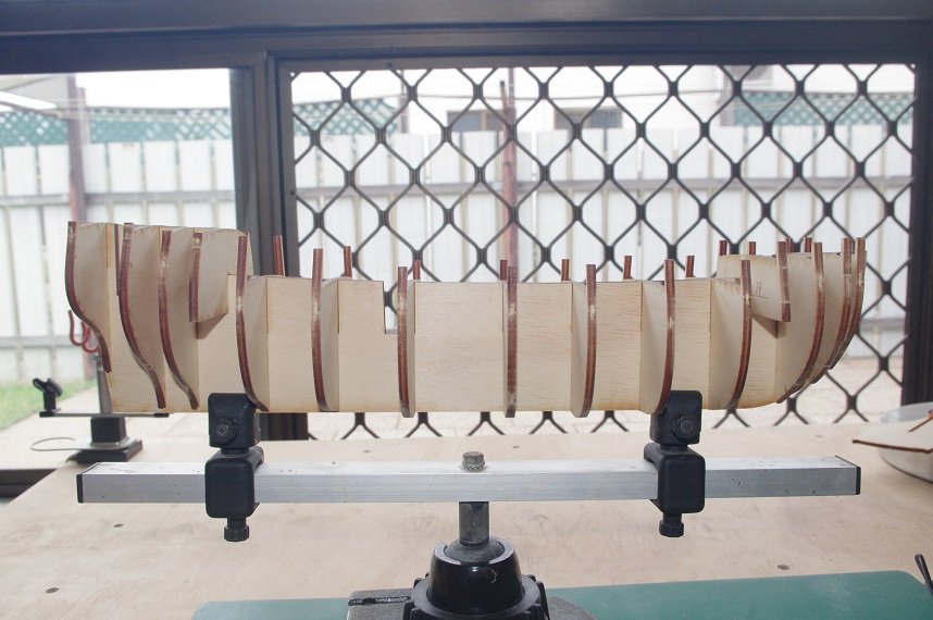
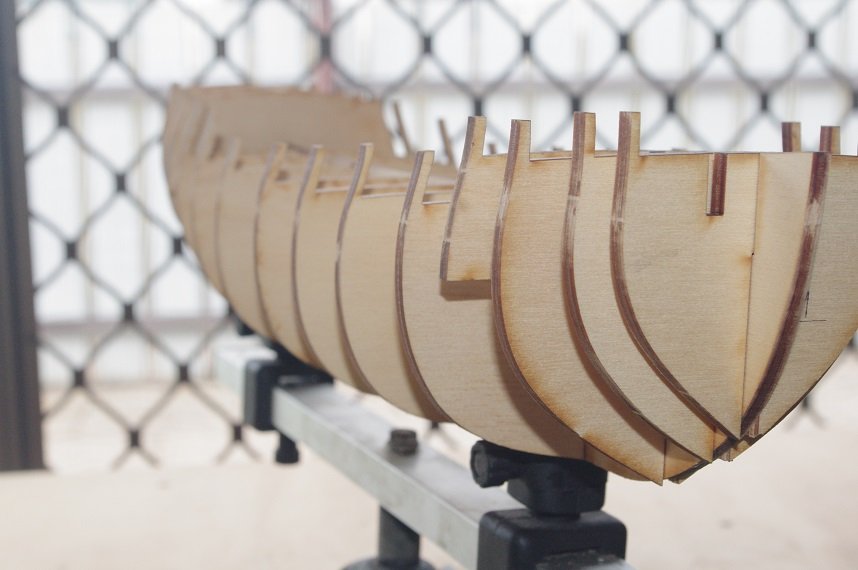
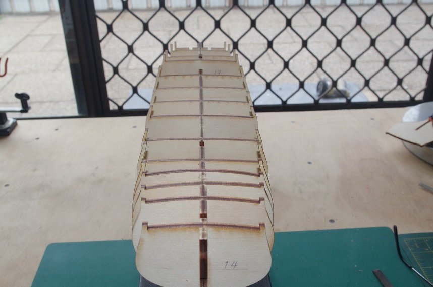
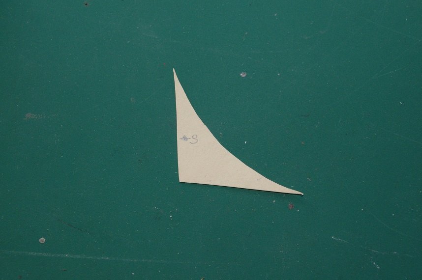
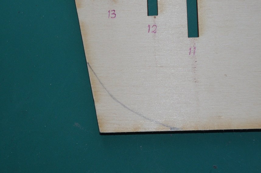
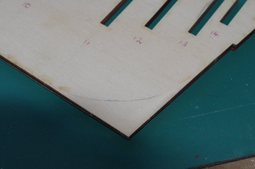
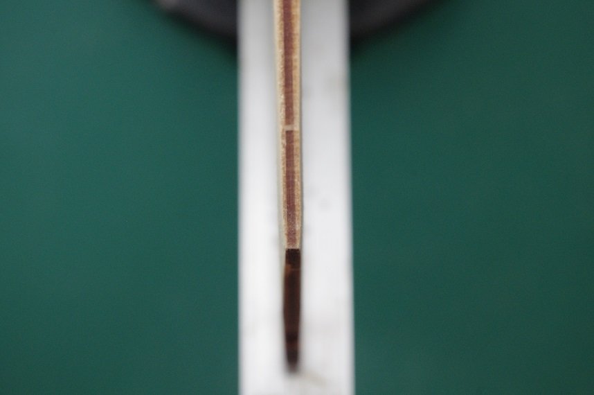
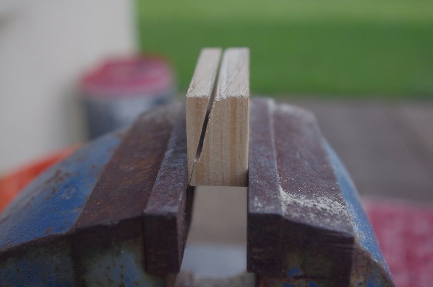
Hello All, With the Pickle nearly complete and just waiting in between for coats of varnish to dry I have made a start on the Supply. All of the bulkheads were numbered and their slots on the false keel were also numbered, they were then cut from the 4mm boards and dry fitted together. Some of them will need shims fitted into the slots so that they are level with the top edge of the false keel while most of them will need their slots squared, both on the bulkhead and the false keel as they have been cut on a slight angle. All of the bulkheads are a nice snug fit on the keel. Before any bulkheads are glued to keel there are a few things that I want do to it. 1. Mark and sand a bearding line. 2. Drill two holes through the keel and into the false keel for pedestal mounts between bulkheads 4 and 5 and bulkheads 9 and 10. I was planning on 3mm holes for the mounts but seeing as the false keel is only 4mm thick I have opted for 2mm holes for now. 3. Drill 1mm holes for dowels through the keel, stern post and stem post and into the false keel. 4. Glue support blocks to the false keel where the pedestal mounts are. So the first job was to mark up the bearding line, a template was made from card of the area around the last 3 bulkheads and using this I marked the line on both sides of the false keel. And then carefully sanded the excess material away on a slight taper so that the rear edge of the false keel was 2mm thick. The first planking will also have to be sanded back in this area as it is 2mm thick and the stempost is only 4mm thick. Thanks for looking and the likes. All comments welcome.
-
That should look very nice.
-
Thanks Keith, yes I will have a little celebration when she's done.
- 86 replies
-
- 1
-

-
- pickle
- caldercraft
- (and 1 more)
-
Very nice work, Keith. Those lanterns will make a big difference, the supplied ones look way out of scale and very plain in comparison.
-
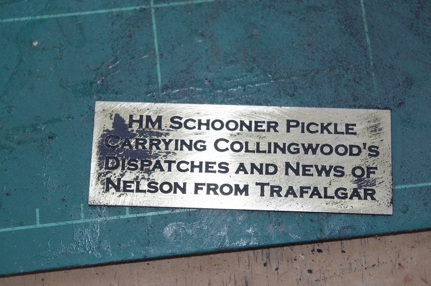
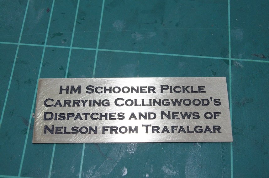
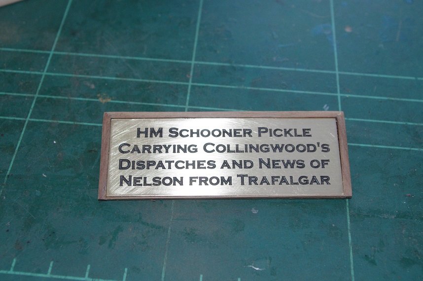
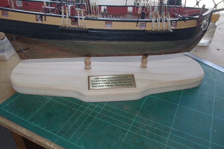
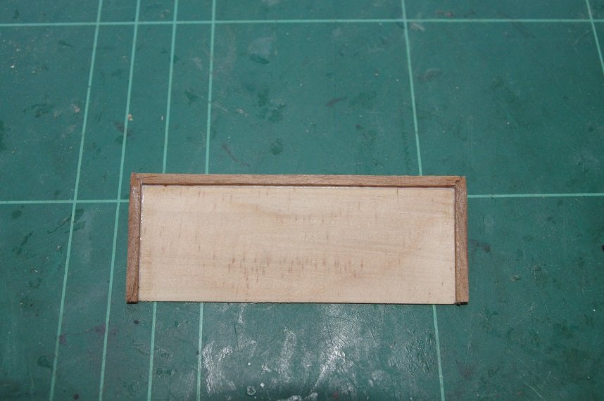
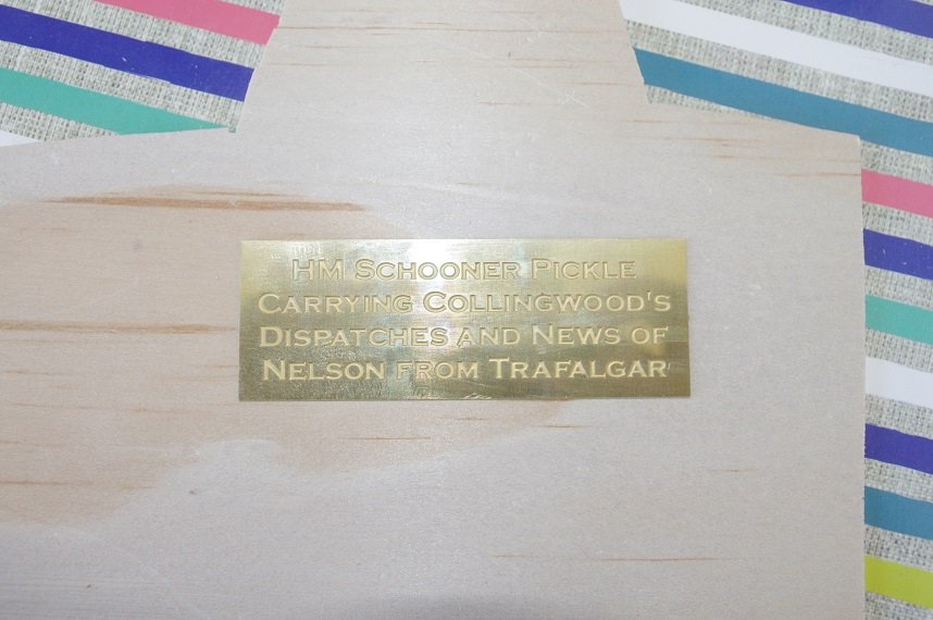
Hello All, Just a quick update, I have sanded back the nameplate and I am very happy with how it turned out. It was test fitted into it's mount Then the mount was glued to the base and when it was dry everything was dry fitted together. It is now ready for a few coats of clear varnish. The first coat was applied a few minutes ago. Thanks for looking and the likes. Comments always welcome.
- 86 replies
-
- 5
-
-
- pickle
- caldercraft
- (and 1 more)
-
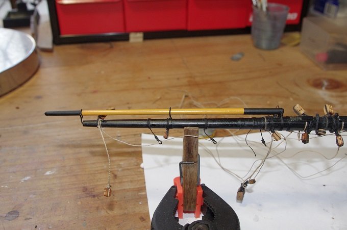
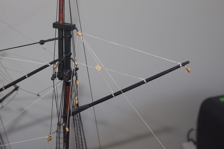
Hi Keith, The stunsail booms look really good as they are but as an alternative I saw in a photo of the Victory taken at Portsmouth a while ago when she was fully rigged and the stunsail booms were painted yellow ochre in the centre and black on each end. I don't know how historically accurate that is but it how I painted mine on the Victory bow section. Or alternatively just paint the end s black. Just my two bob's worth, I hope I haven't confused the situation to much!
-
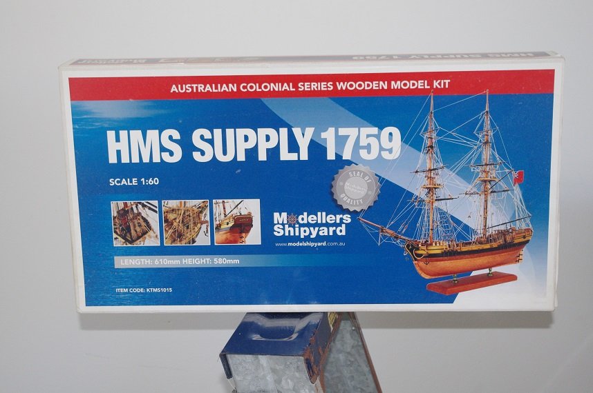
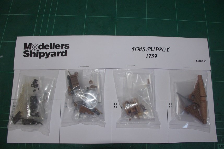
Thanks Keith, with the Pickle nearing completion I thought I best get started on another one. The packaging is rather neatly done with most parts in their own separate plastic bag.
-
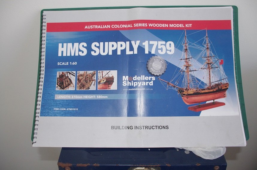
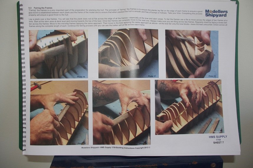
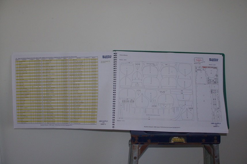
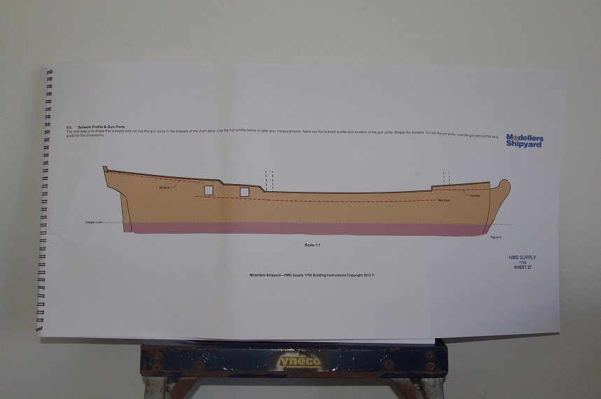
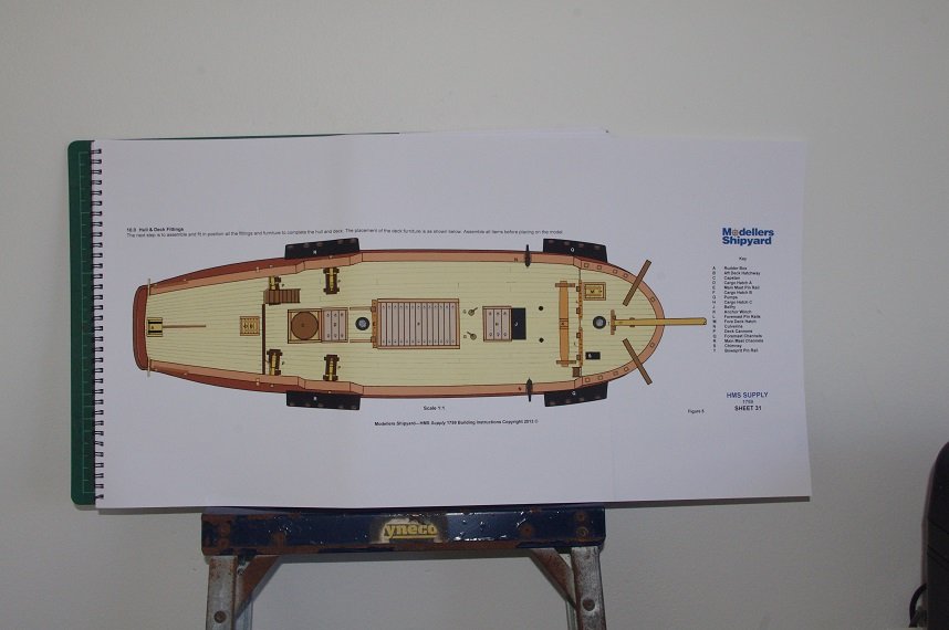
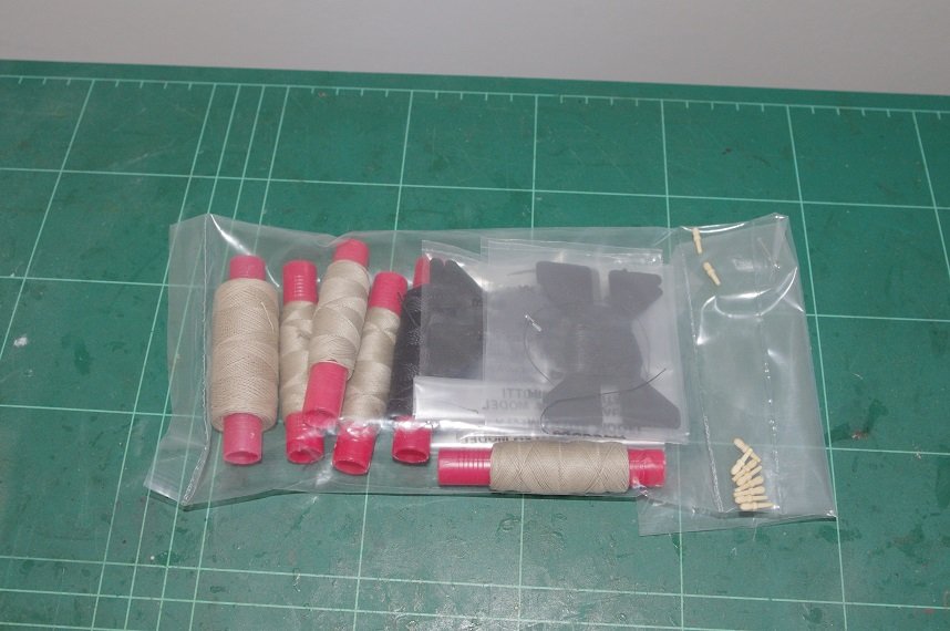
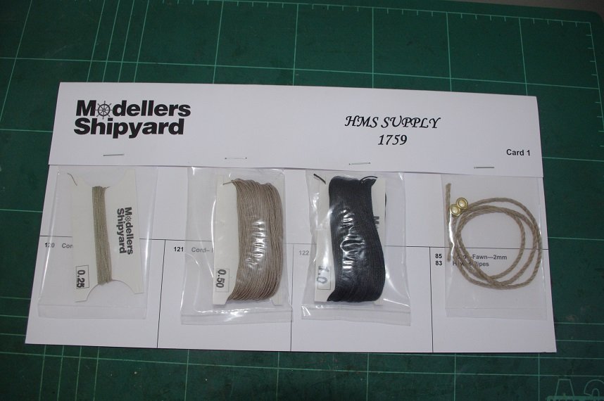
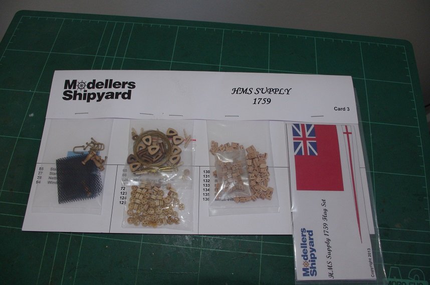
The instructions come in the form of a large 74 sheet booklet which include the rigging instructions and mast and yard dimensions. There are photos of the building stages accompanied by a brief description of the step. There is a parts list and a drawing of the laser cut parts, showing their number in the front of the book. There are some fold out sheets in the book which show the locations of deck fittings ect. but these are not to scale and there are no 1:1 scale plans supplied. Some dimensions are supplied in the description at certain stages of the build but not all the mast and yard dimensions are next to their drawings but the drawings are not to scale but at what distance a blocks are spaced on a yard for example is not so some educated guessing will be required. The main downfall of this kit is the rigging cord which I did not realise before I purchased it that while being of good quality only three sizes are supplied, 1mm black cord for all of the standing rigging, 0.5mm tan cord for all of the running rigging and 0.25mm tan cord for the ratlines. I have since purchased some extra rigging thread in various sizes in both tan and black so that the rigging can be more authentically presented in my humble opinion. Oh and some extra belaying pins too. More to come soon Thanks for looking. All comments welcome.
-
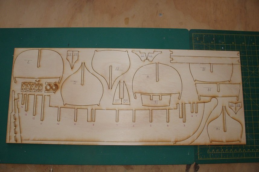
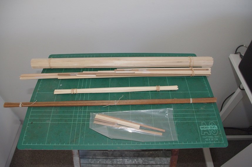
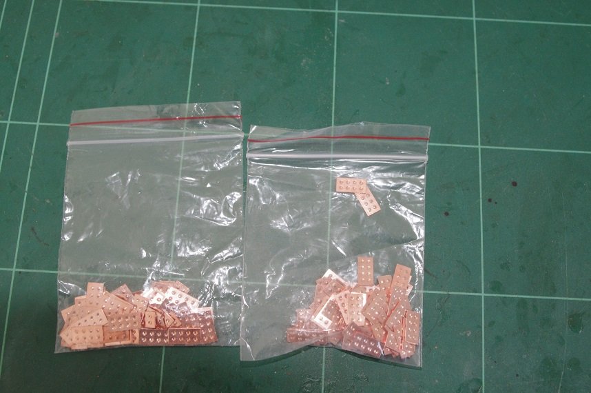
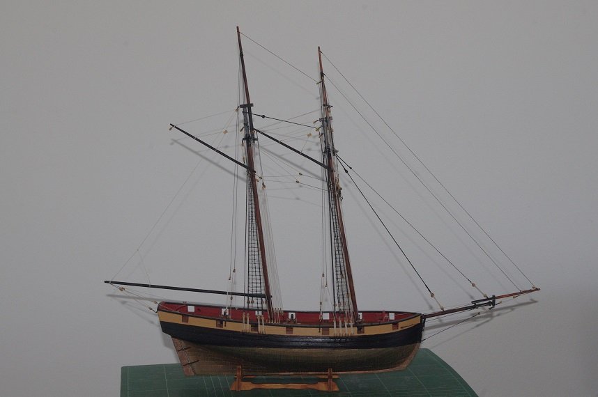
Hello All, Welcome to my build log of the HMS Supply. As far as I can tell after searching through this forum this is the only build log of this ship by this manufacturer. Although I think this will build up to a nice model straight out of the box I will be making a few modifications to enhance the kit. A brief history of the ship. The keel of the Supply was laid down 261 years ago on the 1st of May 1759, she was designed by shipwright Thomas Slade as a yard craft for the distribution of naval supplies. Construction was contracted to Henry Bird of Rotherhithe, a Borough of Southwark in the county of Surrey. The vessel, measuring 168 20/94 tons (BM) was to be built in 4 months at a cost of 8.80 English pounds per ton. Actual construction took 5 months, which is a lot shorter time than it will take me, from the time the keel was laid on May 1 to her launch on the 5th of October. As built she was larger than designed at 174 76/94 tons (BM) and with a length overall of 79ft 4in, a beam of 22ft 6in and a hold depth of 11ft 6in. She was commissioned on the 17th of October 1759. She was a square rigged brig with two masts, was armed with four 3lb cannons and six 1/2lb swivel guns and had a crew of 14 while being used as a yard vessel. When converted to an armed tender in 1787, in preparation for her duties with the first fleet, her crew rose to 55 which included marines and she was fitted with four 12lb carronades as extra armament. The Supply left Spithead with the rest of the ships in the first fleet on the 13th of May 1787 under the command of Captain Henry Lidgbird Ball. Supply was under the command of Captain Arthur Phillip, who had transferred to the Supply from HMS Sirius at Cape Town because the Sirius was deemed to slow, when she entered Botany Bay on the 18th of January 1788. After the rest of the fleet arrived and Botany Bay was deemed an unsuitable place for settlement the Supply was the first ship to enter Port Jackson, a few miles up the coast, on the 26th of January 1788 where a settlement was established. HMS Supply served as a tender to the penal colony until the 26th of November 1791 when she sailed for England arriving on the 21st of April 1792. She was sold out of service and used as to carry coal in the Thames area until 1806 when I presume she was broken up. The Kit The kit is well presented with laser cut parts for the bulkheads, keel, false keel and decks. The bulkheads and keel are out of 4mm ply and the decks 2mm ply. The timber strip and dowels for the planking and the masts and spars looks to be of good quality although I can see some damage to the 0.5mm mahogany strips for the second planking. The prefabricated parts such as the windlass, capstan and deck cannons as well as the rigging blocks, rigging cord and other fittings are all presented on three cards. The bottom of the hull is to be coppered so 1300 copper plates are also supplied these look to be of a reasonable quality also. continued in the next post.......

-
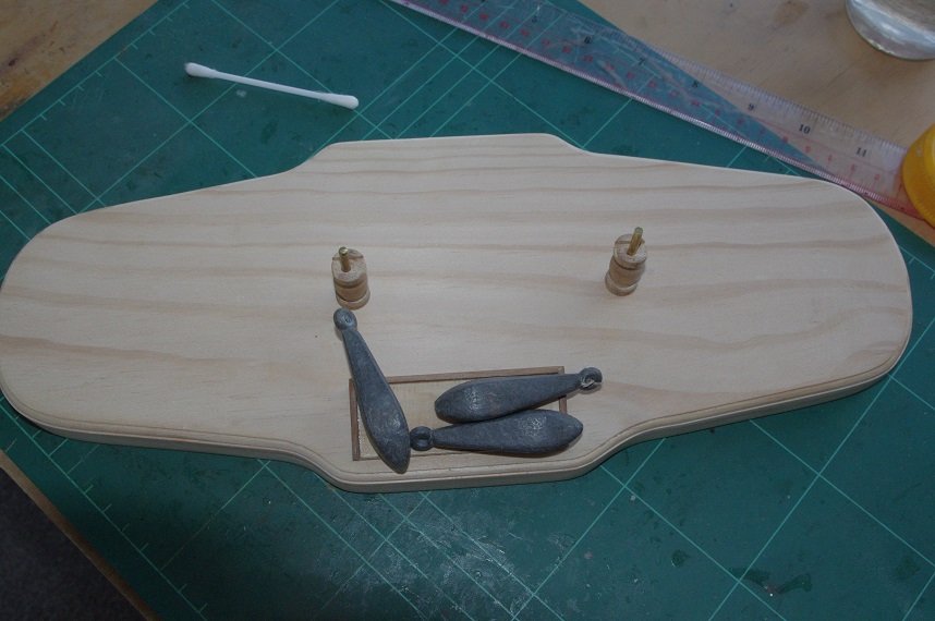
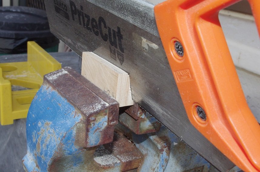
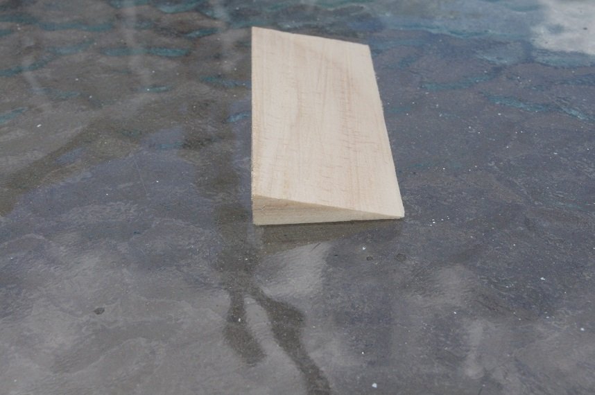
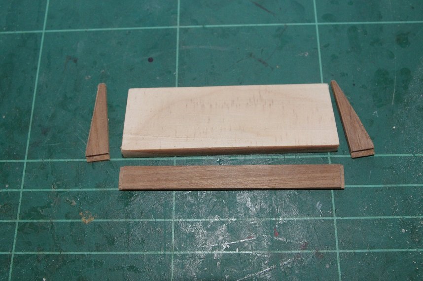
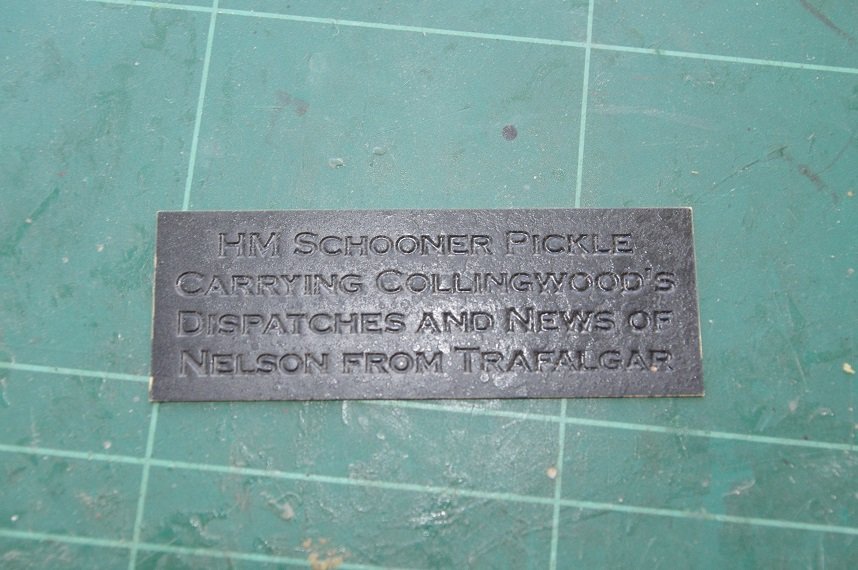
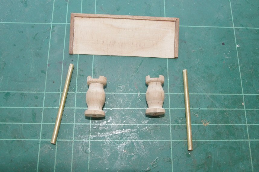
Hello All, A little more progress on the parts for the display stand. I decided I wanted the nameplate to sit at an angle off the base so I cut a wedge from a piece of 19mm pine and then trimmed it so that it was the same size as the nameplate. Edges for the back and both sides were made from 7 x 2mm walnut and glued on. The nameplate was painted black and when the paint dries it will be rubbed back to leave black letters, I hope. The pedestals have also been made, these were turned from a piece of 12mm pine dowel with a 3mm hole through the centre for the brass rods to fit in. The next jobs are to glue the nameplate mounting onto the base along with the pedestals and give the whole thing a few coats of clear varnish. Thanks for looking and the likes. Comments always welcome.
- 86 replies
-
- 4
-
-
- pickle
- caldercraft
- (and 1 more)
-
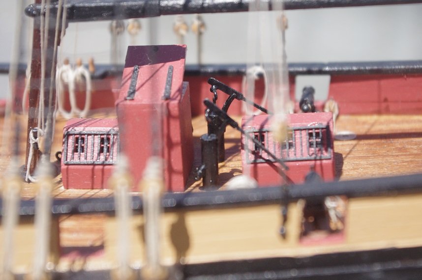
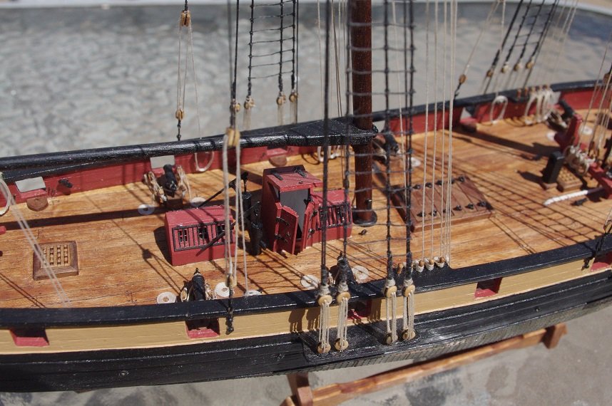
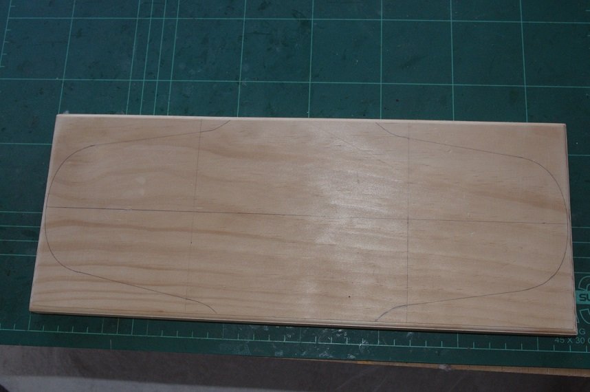
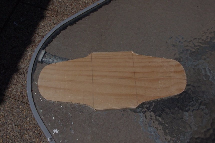
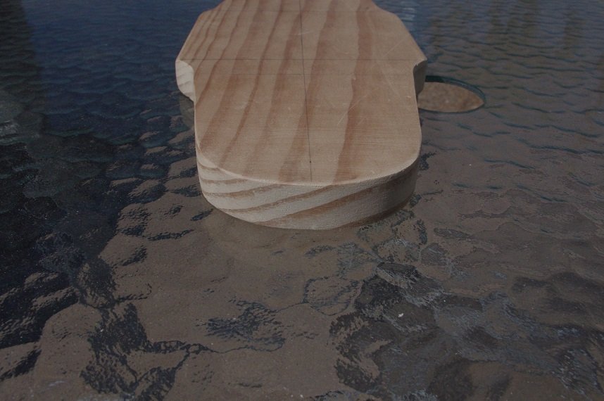
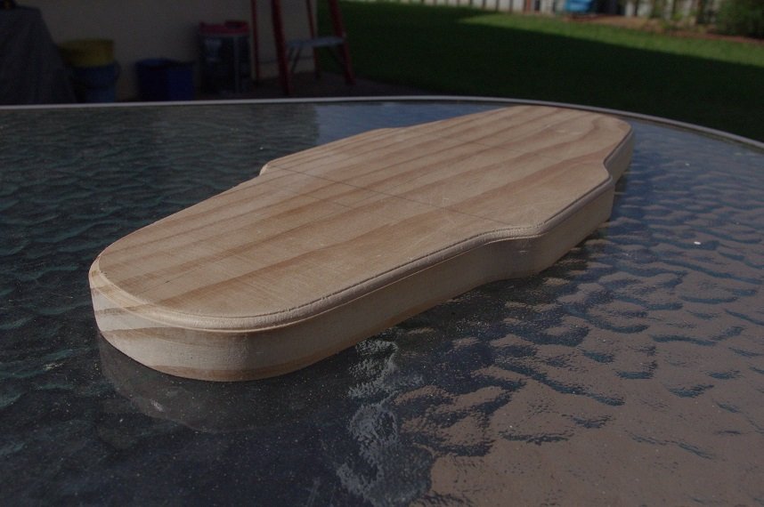
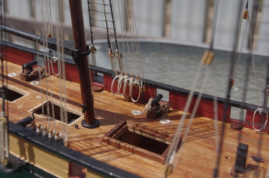
Hello All, The deck houses/ skylights have been fitted along with the companionway, bilge pumps and covers for the main hatch. These parts were all made some time ago and just needed to be glued to the deck. I have also started work on a base to mount the model on, it is a piece of 19mm pine board I had left over from a shelving project. I first cut it into a rectangle and even dressed the upper edge with a 3mm router bit in my dremel but then thought I would like a more curvy shape so I marked on the pattern below and cut it out with a jigsaw. I gave it a good sanding and then re-cut the top edge with the router. Next job is to turn up some pedestals for her to sit on and to make a mounting for the nameplate. Thanks for looking and the likes Comments always welcome.
- 86 replies
-
- 4
-
-
- pickle
- caldercraft
- (and 1 more)
-
Yes Keith, nearly there only a few bits to add to the deck and make a base to display her on. It is unfortunate you can't get your Victory outside for a few shots but understandable, it would be a disaster if you had a mishap taking her outside for the sake of a couple of photos!
- 86 replies
-
- 1
-
-
- pickle
- caldercraft
- (and 1 more)
-
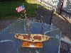
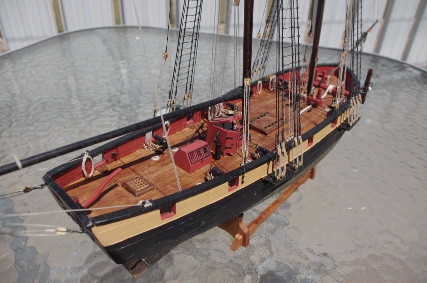
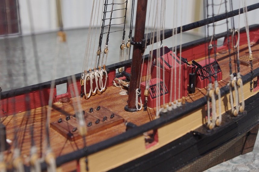
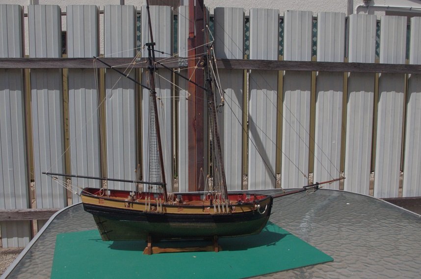
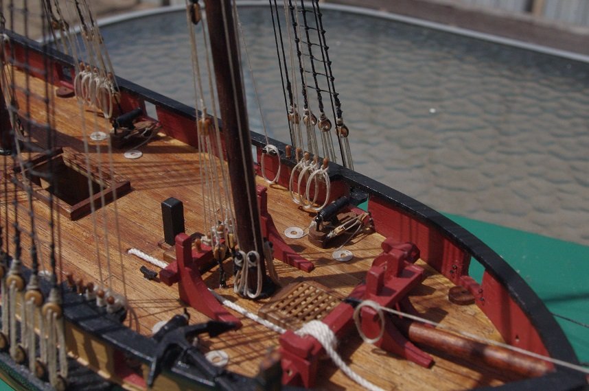
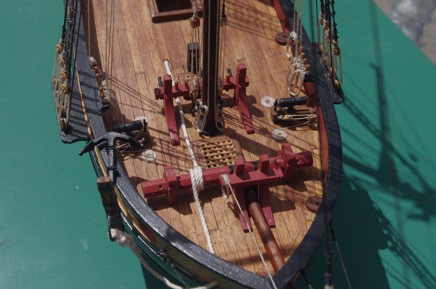
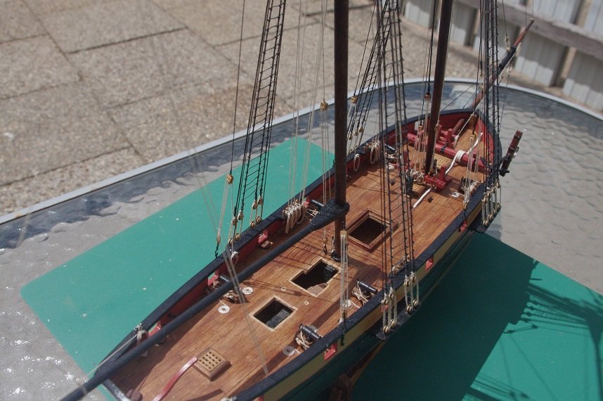
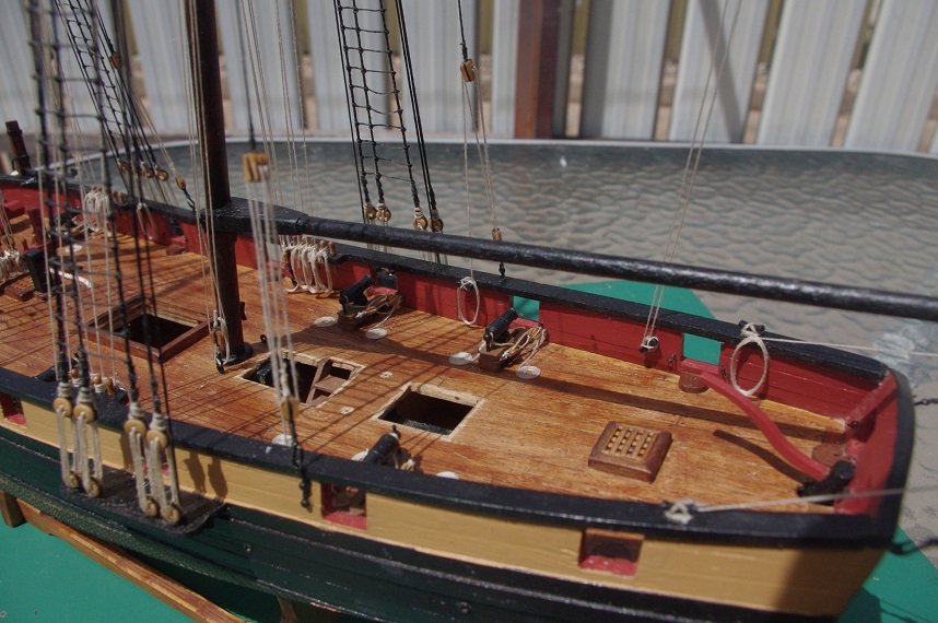
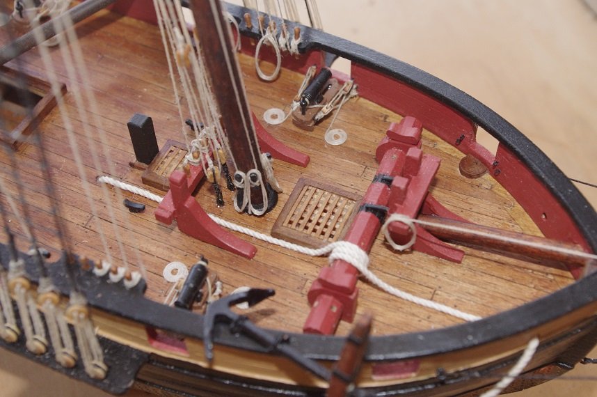
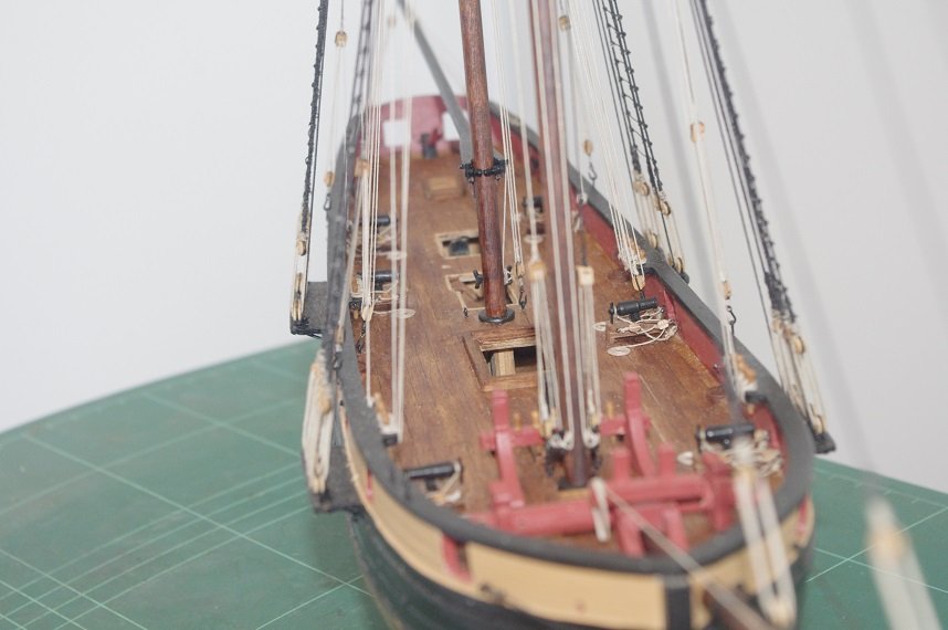
Hello All, All of the rope hanks and coils have now been made and added to the model. I thought I would take some photos of it outside in some natural light before the deck houses are fitted. Thanks for looking and the likes. All comments welcome.
- 86 replies
-
- 4
-
-
- pickle
- caldercraft
- (and 1 more)
-
Coming along nicely, I imagine it would get a bit cramped for room especially with the amount of rigging on her!
-
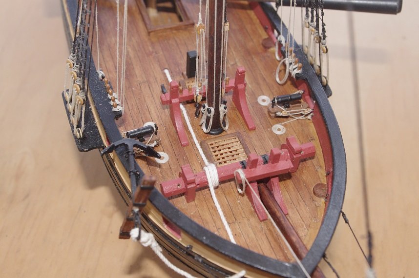
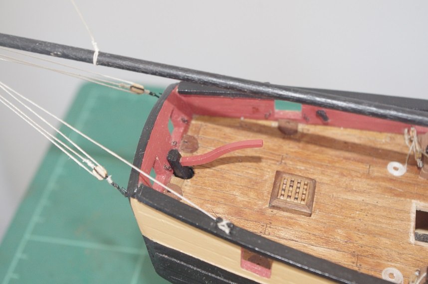
Thanks Keith, I think it is suitable for a smaller vessel such as "Pickle. Another small update the anchor has been fitted. The cable was passed through the hawse hole and around the windlass and finally poked down the navel hole in the deck, it is held down with PVA glue. The anchor is lashed to the two eyelets on the capping rail. Also some more rope hanks have been fitted to the belaying pins and some coils of rope draped over the cleats. I am quite happy with how these turned out. Thanks for looking and the likes. Comments always welcome.
- 86 replies
-
- 3
-
-
- pickle
- caldercraft
- (and 1 more)
-
Looking very neat , Scott, keep it up
-
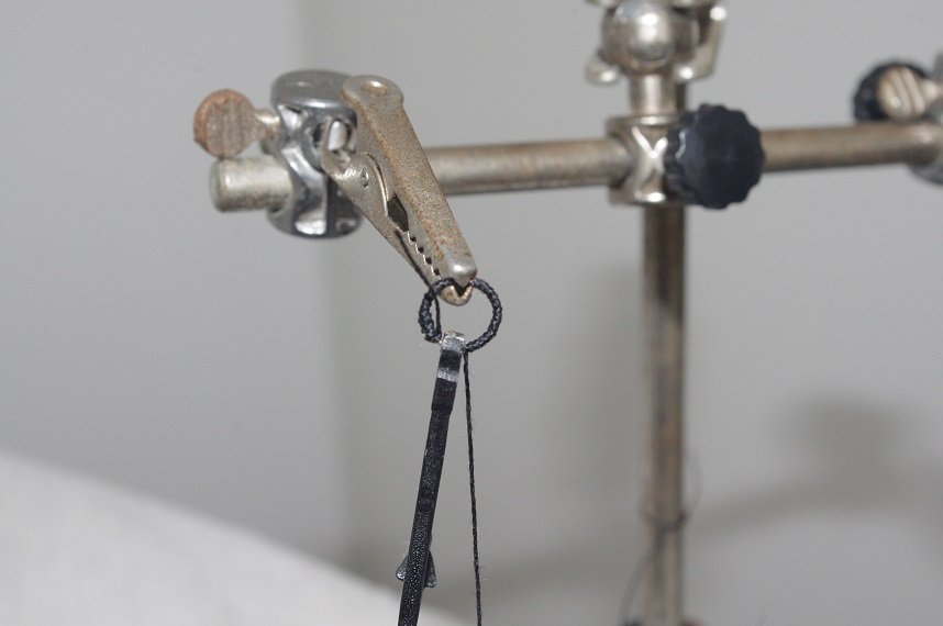
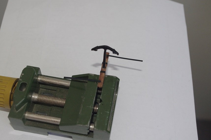
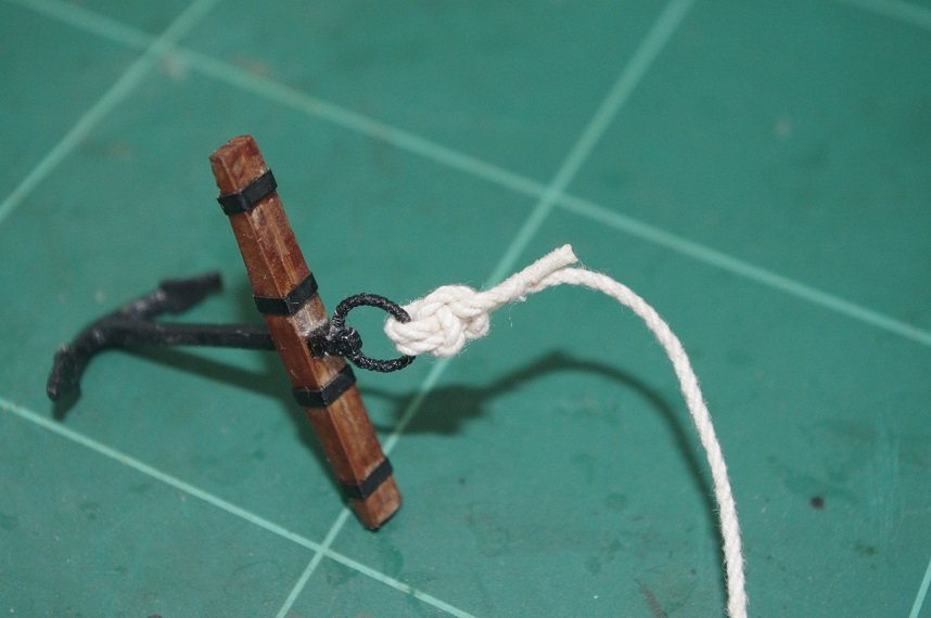
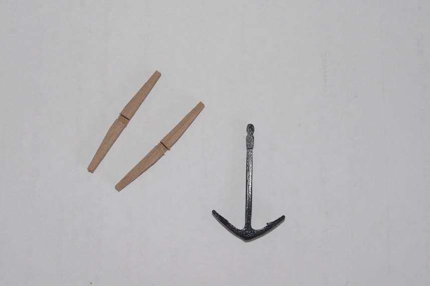
Hello All, A small update, the ring for the anchor was made from brass wire and the puddening added. The anchor stock was then glued on and the bands added, these were made from 1.5mm strips of black cartridge paper supplied in the kit. And finally the anchor cable was attached with a fishermans bend. The instructions call for an inside clinch knot for the anchor but I think the fishermans bend is a more interesting knot and was used on the smaller kedge anchors. Thanks for looking and the likes. All comments welcome.
- 86 replies
-
- 5
-
-
- pickle
- caldercraft
- (and 1 more)
-
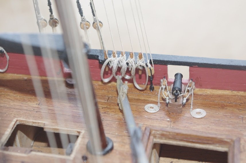
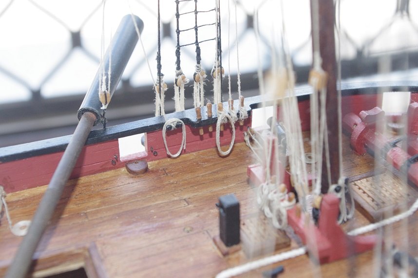
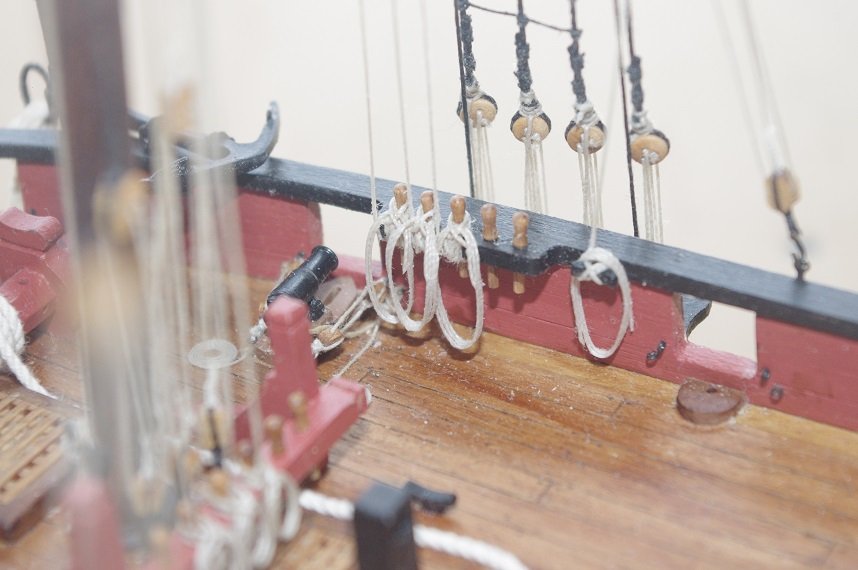
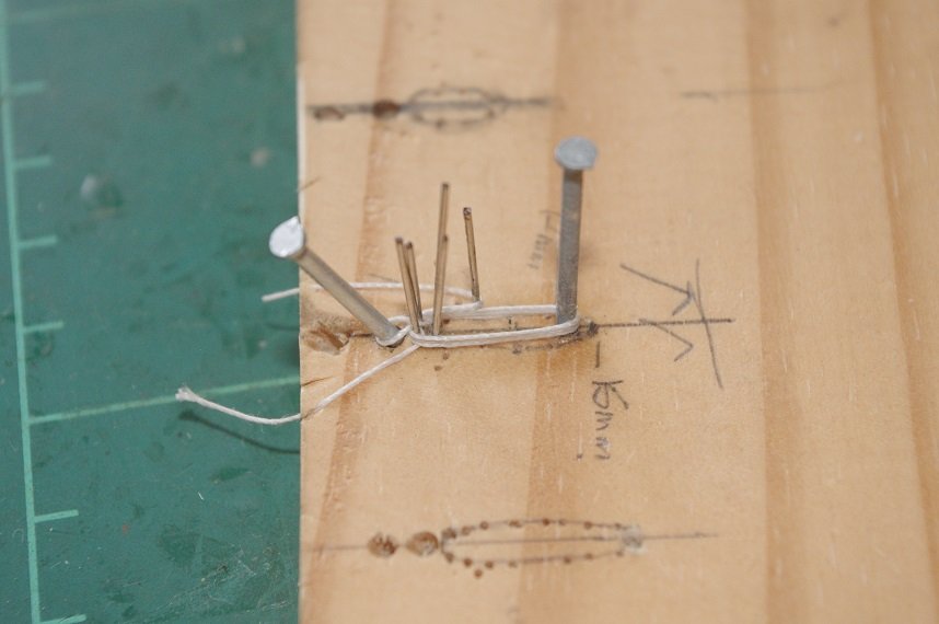
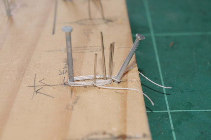
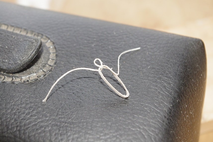
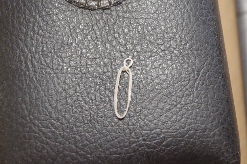
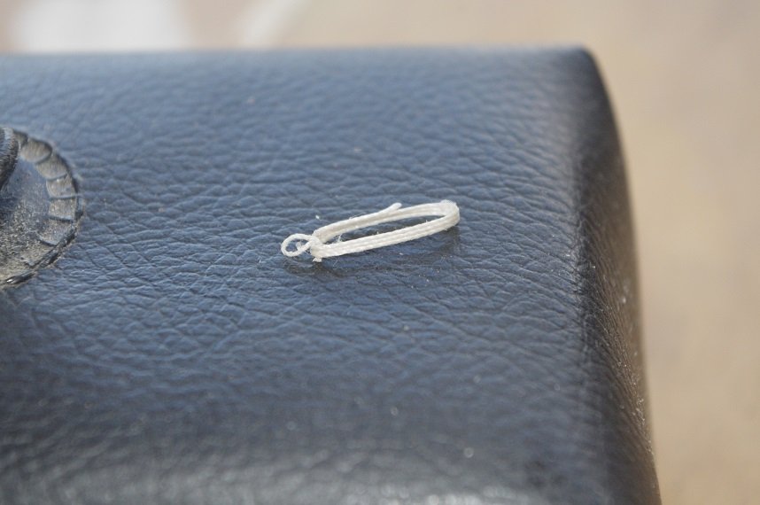
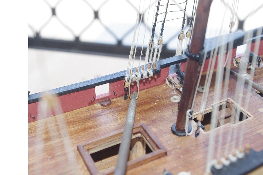
Hello All, I have been experimenting with different methods of making rope hanks to hang off the belaying pins on the capping rail as I didn't like the ones suggested in the instructions. After a few tries I came up with a combination of Tom Lauriett's method and my own. It is basically the same as Tom describes in his video but instead of using pins all the way around the inside of the loop, which makes it too wide and bulky for my liking and is probably the way I am doing it and nothing to do with his method, I used a single nail at the bottom of the loop which made the finished product much narrower. After removal from the jig the ends were trimmed off. The hanks are 15mm long measuring from just below the eye to the bottom of the loop which allows them to hang just above the deck on Pickle. The hank is then placed over a belaying pin and the eye is brushed with some diluted PVA glue and held in place with a weight till it's dry. The flutes have been glued to the anchor and it has been painted black. Comments always welcome. Thanks for looking and the likes
- 86 replies
-
- 6
-
-
- pickle
- caldercraft
- (and 1 more)
-
Thank you very much Keith, I have enjoyed building this kit as it is well designed and the supplied materials to build it are of a very good quality and there are plenty of extra parts in case you make a mistake or loose one. I am sure your Endeavour kit is up to the same standard and having just looked at your build of the Victory I am sure it will turn out beautifully.
- 86 replies
-
- 2
-
-
- pickle
- caldercraft
- (and 1 more)
-
You are doing a wonderful job on her Keith, lovely work.👍
-
Thanks Mugje. The finish line is getting closer by the day.
-
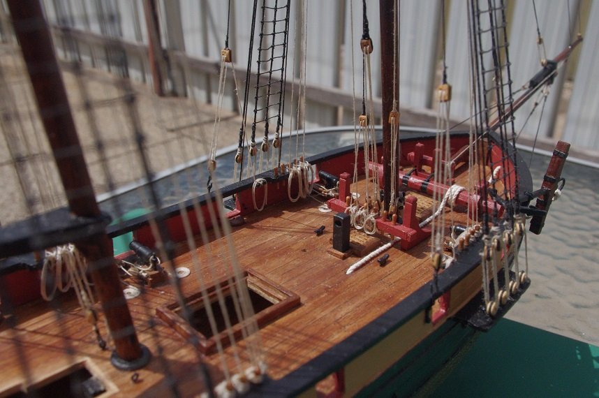
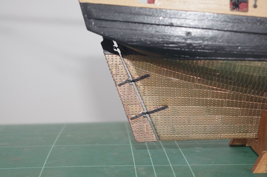
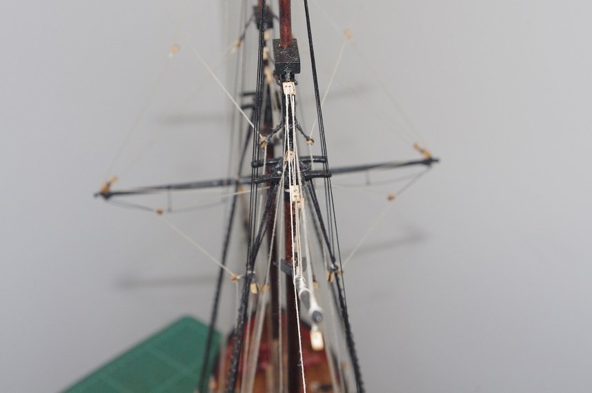
Hello All, The rigging for the main gaff was set up. The topping lift is the same as the fore gaff except that it belays on the port aft cap rail pin-rack. The main gaff also has a throat halyard instead of a sling and this is reeved between a 3mm double block attached to the starboard side of the main trestle tree and a 3mm single block tied to an eyelet on the jaws of the gaff, it belays on the starboard aft pin rack. The rudder and driver boom have also been fitted and the driver boom rigged. The guy pendants are rigged through a 3mm double block on a 15mm pendant tied to the end of the boom, a 3mm single block is hooked into the transom and the falls tied to the end of this block is reeved through the two blocks and belays on the cleat on the capping rail. The topping lift standing end is tied to the end of the boom and goes up through a 3mm double block attached to the mainmast cap then down towards the deck where a 3mm double block is tied to the end of it 96mm from the deck it is rigged with a 3mm single block hooked into the deck and belays to the starboard cleat on the mainmast. The mainmast back stays were also set up, they are rigged the same as the foremast backstays. And the last line to be rigged, the main topgallant stay, was tied off. It had been tied to the forestay collar earlier and only needed to be seized to the main topmast. That completes the standing and running rigging for this ship. The next jobs are to make rope hanks and coils to drape over the belaying pins and cleats and to construct and fit the anchor. Oops! just realized looking at the last photo, there is one more line to rig, the flag halyard.
- 86 replies
-
- 9
-
-
- pickle
- caldercraft
- (and 1 more)
-
Excellent job on the anchors Eamon, as Caleb said they look like the real thing.👍
- 1,039 replies
-
- 1
-
-
- ballahoo
- caldercraft
- (and 2 more)