dafi
-
Posts
2,434 -
Joined
-
Last visited
Content Type
Profiles
Forums
Gallery
Events
Everything posted by dafi
-
 Thank you for all the feedback. I was made aware that the Most Honourable Order of Garter not only was used for the cathead, but also for other decoration, her the stern of a small frigate. 36 Gun Frigate Scale 1:48. A contemporary full hull model of a 36-gun fifth-rate frigate (circa 1801). SLR0643 https://www.rmg.co.uk/collections/objects/rmgc-object-66604 XXXDAn
 -
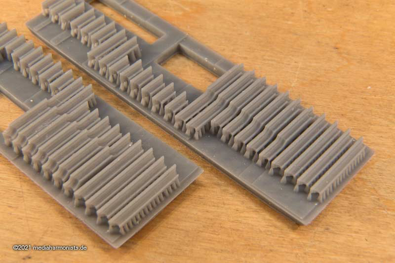
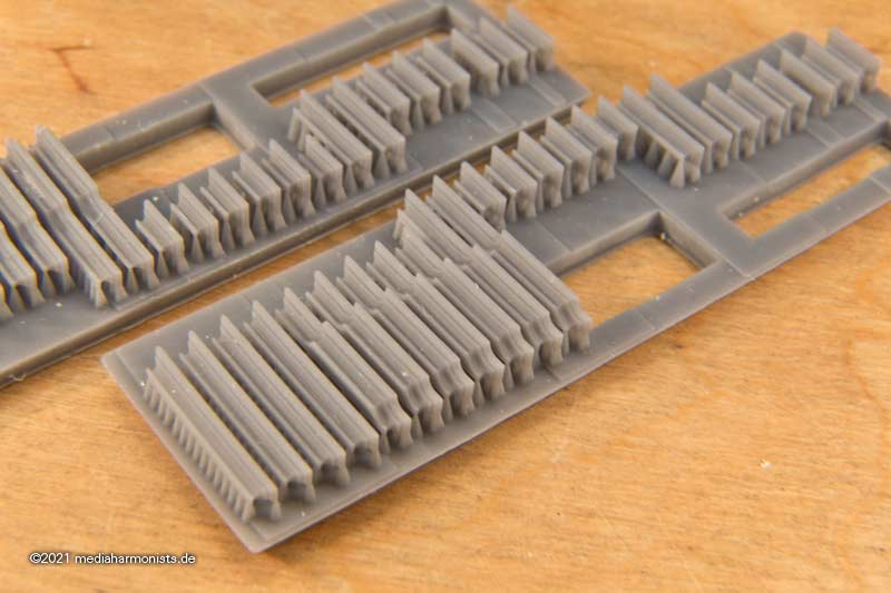
As the better is always the enemy of the good, here comes the next step, or better saying come the next steps. Stairway to heaven 🙂 XXXDAn
-
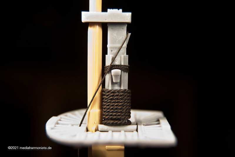
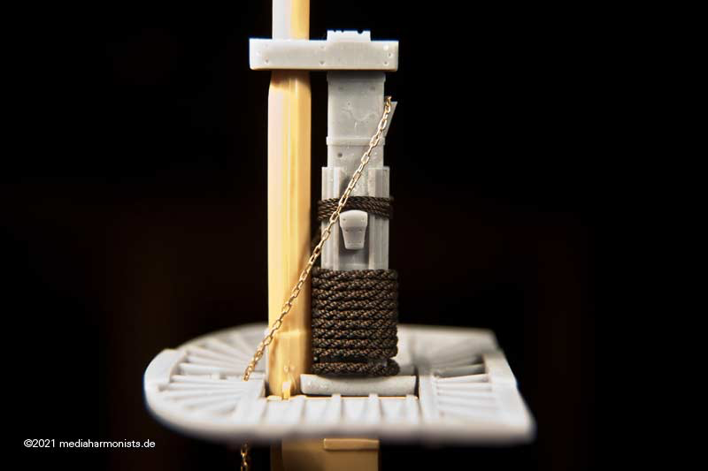
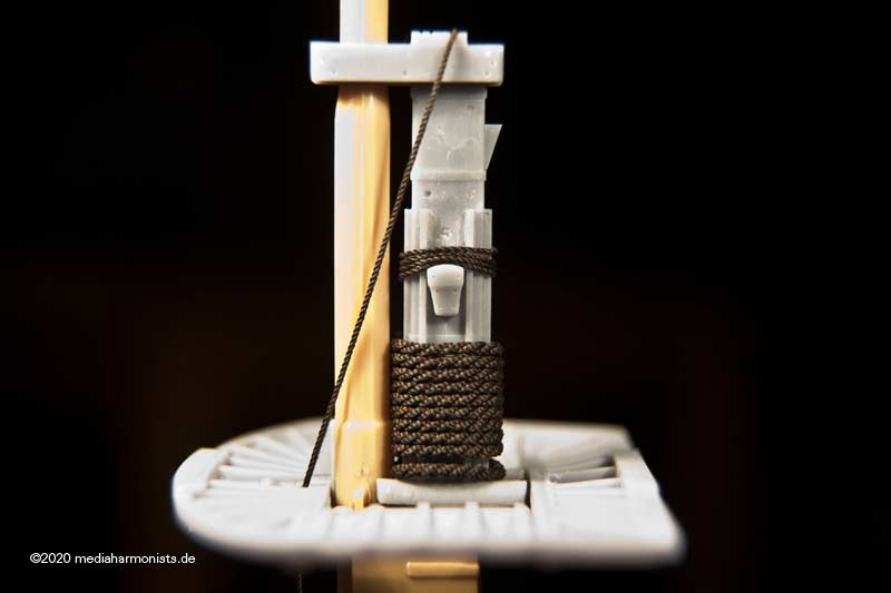
Thank you @druxey, this one is for the hanger. But you are correct in times of war most systems were redundant. This would then be like the last picture in my last post showing the chains and the rope over the top. It makes sense to attach the chain on the cleat in the back, as there are the sharper angles, no problem for the chain. The rope instead would profit from the radiuses of the bolster. Would the chain be smartened in the ared of cleat, edge of the masttop and the jeers cleat? Would make sense but never really jumped to my attention. Also still have to fiddle out how all that fitted to the yard ... 🙂 XXXDAn
-
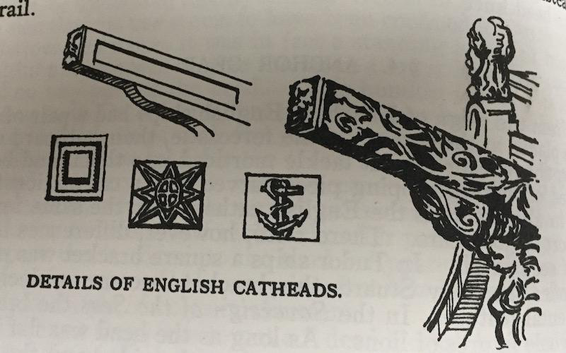
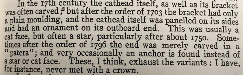
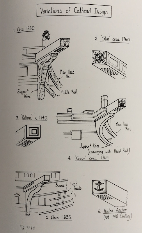
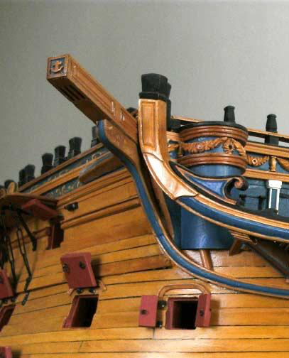
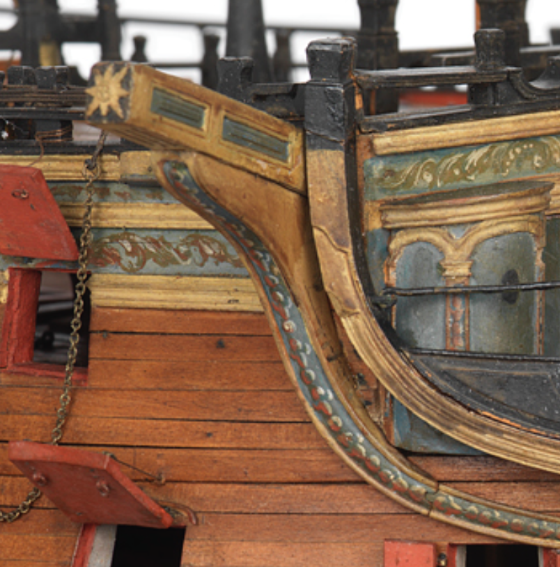
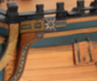
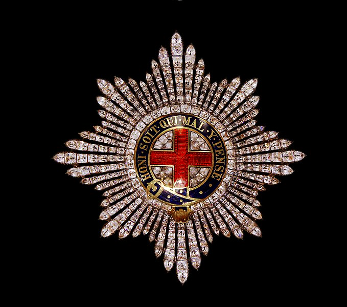
Thank you Jason, it was a while that I was made aware, that the crown seen today on Victory´s cathead is not an usual symbol to be placed there. At the times when the Victory was build, there was a "star" (even Goodwin puts it in brackets) that I believed to be a compass rose. But still the design did not fit with the classical compass rose, which by the way was used often for the flooring in the captains´ cabins and which looks like we know it. It is the vertical cross in the middle with the circle around that irritated me. Alternatively fouled anchors (f. e. HMS Queen Charlotte) or simple cassettes could be displayed there. The one contemporary model of the Vic shows this "star" The other contemporary (?) model shows the color inlays This is what L. G. Carr Laughton reports in "Old Ships Figure-Heads and Sterns" Goodwin shows the crown (wrongly for 1765 - earliest 1803) but also quite clearly shows the "star" as no compass rose Here @achilles well researched model of Queen Charlotte, following the contemporary model. Quite clearly HMS Boyne 1790 Also this Sectional model; Bow model SLR2185 And the final clue was the NMM itself, but only after I was pointed by a german forum´s comrade towards this possibility: HMS Vanguard (1835); Warship; Third rate; 78 guns, 1835 The catheads are depicted, their ends being painted with garter styles. Warship; Frigate Scale: 1:48. SLR2197 "... Fittings include a pair of catheads with garter star end decoration; ..." And here it is again as comparison, the Order of Garter. And it makes completely sense, as the Order of Garter was also incorporated in the Royal Coat of Arms and therefor in the figure head of the Victory 1803. Honi soit qui mal y pense 😉 XXXDAn
-
Thank you druxey, I am quite with you there, but still ... And I've gone through the different possibilities that come into question for the hangers. The ropes are just place holders. The jeer cleat could be placed a tiny bit down what would ease the case, but still ... One sees, that the bolster on the cap is the most elegant solution. I don't know to what extent the hanger running over the jeer block lashing tends to chafe here, since both parts are static. Above all, the fact that the stopper cleat at the rear is the only version mentioned in contemporary sources gives me reasons for further investigations. Only the bow-shaped jeerncleat I would have reservations about the hanger running over it; here the two actually interfere with each other. I'll keep digging. XXXDAn
-
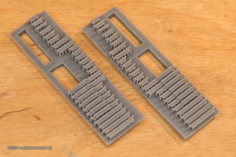
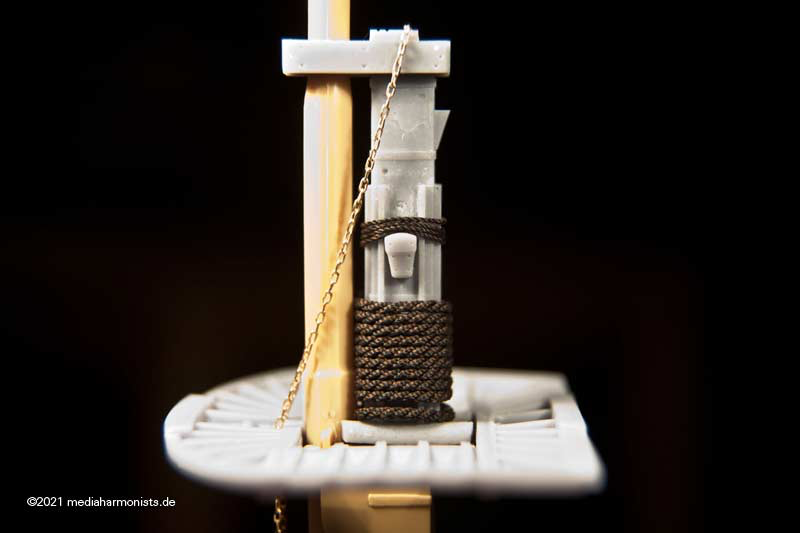
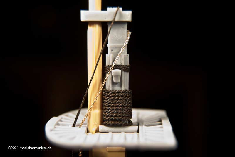
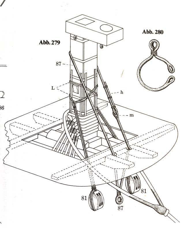
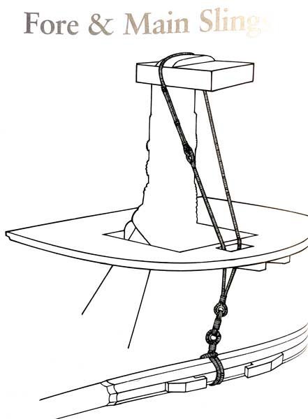
Did not have the chance to real tinker in 3D so I tinkered at least a bit digital in 3 D 😉 Gives the chance to overwork the parts, try out things and so to clarify the last issues and uncertenties that I have in some points. After the cleat for the fore and main yard jeers*** comes the other one 🙂 But first, also here the difference between the kit on the left and the classically tinkered fore mast on the right, which can be recognised by the missing rake of the bolsters 🙂 Redefined the mastcap, showing the splitlines and now also including the small and seldom seen detail, the triangles of the leather lining in the hole for the topmast. My uncertinty is upon the two bolsters of the cap: The front one with two thin grooves is for the lifts, the thicker aft one is for the yard slings. Were they in use in about 1800? The two thin grooves are meant for the yard lifts, a version seen in Portsmouth and Klaus Schrage and K. H. Marquardt. Here the blocks are not hanging on eyebolts underneath the cap, but are led on a doubled rope over this bolster, as shown by Schrage. Here is the question, if there are any information about the attachement of those lift blocks in 1800. Was the front bolster used for the blocks of the lift or were they fixed with an eyeblot from underneath the cap? Next question is about the aft bolster with the thicker groove for the lead of the yard sling (blue arrow). Again this use is found in Portsmouth. Here also I found two versions, as most other sources, contemporary and also modern ones indicate a stopper clamp on the aft side of the mast head (green arrow). The aft bolster is according to Portsmouth and Pettersen. The aft cleat according to most other sources. Another point that I was realising. Lees claims, that "... these rope slings were changed to chain slings during wartime ...". As 1803 to 1805 the war against France was raging fiercely i was opting for those chain slings for my Vic. A test fit revealed that the version with the bolster keeps nicely clear the jeer block lashing. - do not mind the top tackle in the picture 😉 On the other side the cleat in the back is a quite tight fit. Here in my opinion the stopper cleat in the back is to low and the cleat for the jeer block lashing too high, so that they collide. Again any information about this issue available? Is the bolster obsolete or a good version? Also, if the cjain slings are used, was there still a preeventert rope sling? As always, greetings from a wondering dafi ... XXXDAn ***
-
Attachment of the yard jeers Royal Navy about 1800
dafi posted a topic in Masting, rigging and sails
Did not have the chance to real tinker in 3D so I tinkered at least a bit digital in 3 D 😉 Gives the chance to overwork the parts, try out things and so to clarify the last issues and uncertenties that I have in some points. But first, the difference between the kit on the left and the classically tinkered fore mast on the right, which can be recognised by the missing rake of the bolsters 🙂 The kit provides two bow-shaped cleats at the masthead to suspend the jeer blocks, as also last seen on the Vic (when she was still masted). Portsmouth, McKay and Peterssen show that sort of cleat. Actually I found no contemporary source showing this form ... On the other side all the contemporary sources I found, among them David Steel, but also modern sources like James Lees, K. H. Marquardt and Klaus Schrage, see a shoulder-shaped jeer block cleat at this purpose. Here the two versions in comparisson. For the tackles itself it does not make any difference. Both sitting on the same place. The clamp shaped one is probably more difficult to set op as the rope has to be led through, but gives some protection against falling off while doing this. Once set I believe both versions to give the same support. Since I assume that both variants were once in use, here the question:. In which time frame or on which class of ship these variants were to be applied? I haven't found anything on this yet. I also found the shoulder variant much pre 1800 and also much later, so I believe this to be the more plausible variant. Is there any info about the clamp shaped cleat available? All the best, DAniel-
- 1
-

-
After having finished some touch-ups, the slots of the rollers at the end are round - usually the inner edges were drilled first - and also the hole for the stopper knot of the cat tackle (or fot the cathead stopper?) is there now. Also the cleat now sits in such a way that the bolts to it should not get in the way with anything else. And this leads me to the next question. I had always assigned the hole in the beam to the cat tackle. It makes sense to take it directly behind the slot for the fixed end. However, Marquardt assigns it [i]also[/i] to the cathead stopper and leaves the attachment of the cat tackle unclear. In my model, I had previously assigned the cat tackle to the hole and placed the cathead stopper around the beam secured by an eye. Who knows more about this? XXXDAn
-
Thank you guys 🙂 As I said, I needed some touch-ups, so I rounded the slots of the rollers at the end - usually the edges were drilled - and also the hole for the stopper knot of the cat tackle (or for the cathead stopper??) is there now. Also the cleat now sits in such a way that its bolts to should not get in the way with anything else 🙂 Checking the angles, fits so far 😉 And then first the colour samples. Here is the pure colour. And then my usual treatment with black ink in the inner edges and white brushing of the outer edges. It looks quite different again 🙂 And here is the Order of the Garter in its original colours. Whether it was so colourful around 1803 is questionable, since all decoration was cut back. Therefore, inspired by contemporary models, here is another version. XXXDAn
-
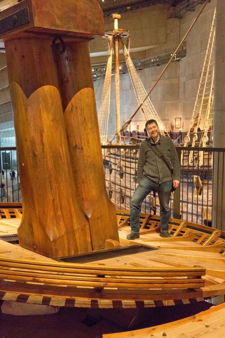
Anyway nothing can be worse than Vasa´s top, with an inclination that makes it really difficult to stand ...
-
Yes Kevin, those are the battens. Those are needed while the top is lifted upwards as there is no other stabilization in between the planks and also after the rest on testle and cross trees to keep the package together. The radial layout is also makes sense as the planking underneath is overlapping so this angle is good to keep both direction of planking together. XXXDAn
-
Hello Kevin Do you mean the battens or the 2 stringers? The single planks were needed as for the size of the top. To hold this planking together those circular battens of the traditional pre 1802 tops were needed. In 1802 came the order to build the tops out of fir - instead of oak as previously used - and in two halves as for more easy replacement. That changed the layout of the battens and also needed the introduction of the 2 big stringers on the topside, that acted as counterpart to the crosstrees. Her in the Ulffers Seamanship of 1872 shows nicely the advantage of the new design: right side and middle the traditional top, left the new halves. Also Nares 1862 shows this feature. All the best, DAniel
-
If you heat up the cured resin it happens the same thing as with the classical cast resin: it gets soft. Good to bend them if they got warped by time or wrong storage, just put a minute or two into warm water - or earl grey hot as Jean Luc used to say - and put them back in shape before cooling down or use the heat to do funny tricks. That was possible after warming up my balusters 🙂 XXXDAn
-
Thank you all 🙂 I think it makes the difference that I am a model maker transferring my knowledge into the printing opposed to many programmers transferring their knowledge into model making. It really helps that I produced all the parts by hand first, as it gives a feeling about the needed details and also on how things have to be altered, like what detail has to be emphasized in what way to appear "real" on the model. If I do the programming strictly by the plans, it only looks half as good 🙂 The mast are not an option, even though they would need it badly, but the resin is much too brittle for that. I think the art of model making is also to know, which is the most appropriate material for a job, in this case it is by my experience a rework of the steel reinforced kit masts with redone iron hoops or a complete replacement with wooden masts. All the best, Daniel
-
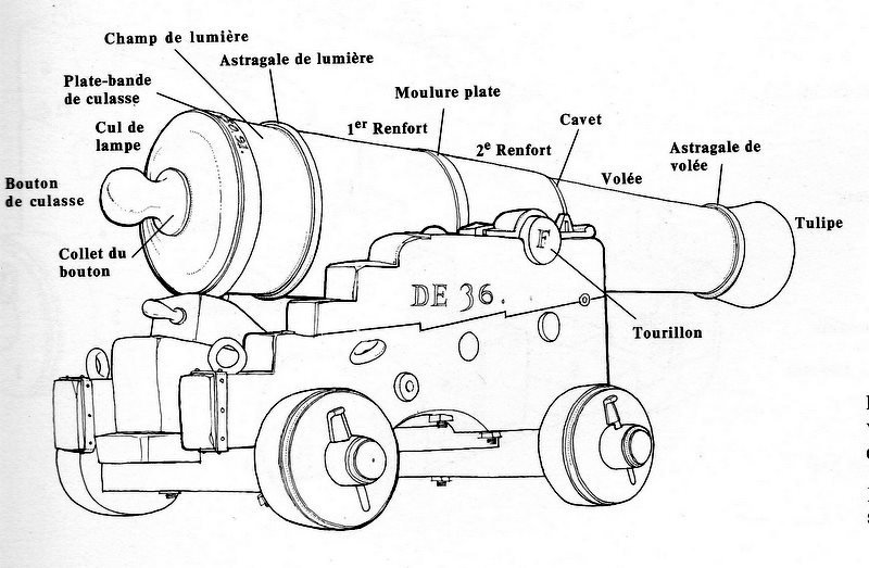
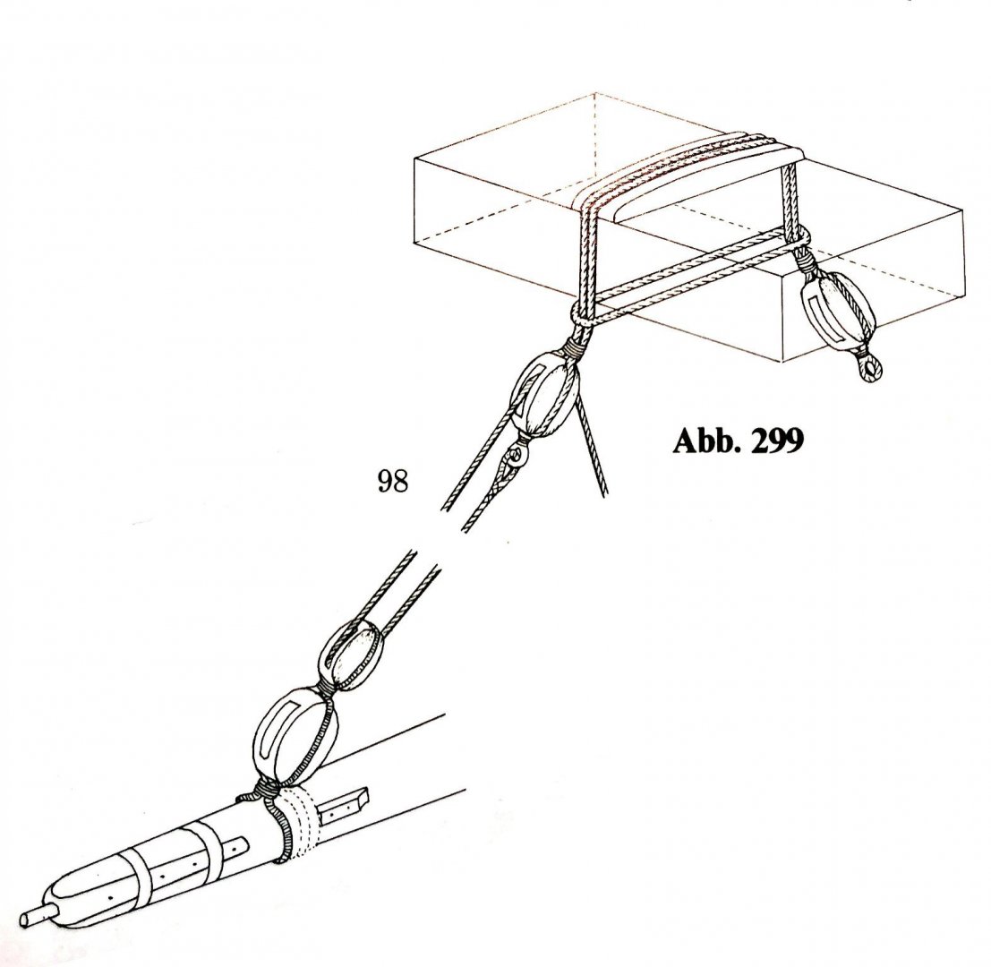
Since I haven't had time to do any real tinkering lately, I've done some more research into the details. My usual subject is the Victory of 1803. On the left, the kit´s cathead. With all the joints and sink marks at the bottom of the cassettes, it was very difficult to get it ship shape and I also had to build in the slots for the pulley for my model. Why not do it right then? The first draft in the middle still had the dimensions of the kit part and also the cassettes were flat leveled inside, but it had the slots and a compass rose instead of the anchor symbol. It was noticeable that the beam was too narrow, which weakened the remaining material between the slots, as the large anchor had to be able to hang on it. Probably the thickness of the kit part was due to the maximum thickness of the casting, you can tell by the sink marks that even that is more than borderline ... At this point of discussion I was pointed by a german forum comrade that what I was believed to be a compass rose was most probably the Order of Garter. Having a closer look I even found some catheads showing exactly those colors, white background, red cross and blue circle, possibly in original with the lettering on it. Therefore a new version, with a square diameter to widen the slots and also the cassettes´ bottoms got a cambered surface, as it is often seen in contemporary sources. The axle of the rollers is now also recessed so that nothing can rub. Also the order was shown more prominent. Still the edges of the slots have to be rounded and the cleat to be positioned more downwards for that its bolts do not foul the slot. But now the next question to the esteemed public: Was the cleat used on english ships around 1800? I sawn them displayed in Chapman´s work and on the model of HMS Vanguard (1835) - but all of them in the frontside and not in the back of the cathead. Also how was the fixed end cat tackle attached to the cathead in 1800? By a hole and a stopper knot on the up side of the cathead? By a sling around the cathead? Or by an eyebolt on the side of the cathead? All these versions I already found displayed in the literature. XXXDAn
-
Since I can't physically get to my tinkering place at the moment (moving box stacking place), here are at least some further developments on some detailed topics 🙂 The cathead in Portsmouth displays a crown. So far no historical evidence of this use was to be tracked down by my knowledge. One favorite of those days, als displayed on the contemporary 1765 model of the vic was a what I believed to be a compass rose. A german forum comrade pointed it out to be the Order of the Garter, and if one looks carefully some models really show those colors on the star. So here is the new cathead with the Order of the Garter as decorative plate instead of the well known but possibly incorrect crown. The first picture shows the kit part, then the first draft and after that the optimised version: The proportions were adjusted, the star of the order was emphasized and the cassette compartments got the cambered base typical for the time. However, there are still a few small things to be done. The two-part fighting top, the masthead and the cap have also been reworked again. But as usual, every corner solved draws two new ones behind it 🙂 It remains exciting. Greetings, Daniel
-
"Would it it be easier to just add the evergreen pieces to the back side of the channel where it will be attached to the hull so I would not need tomake new holes for the irons? Or did you try this and found it not to be satisfactory?" Of course you can 🙂 I felt more confident to use the original pins of the boards to fix them on the hull and also as the curve towards the hull is just right. But it works both ways. "It looks in the plate 3 pictures that you added evergreen to all the channels, not just the fore channels. Is this correct? If so, how much wider did you make the main and mizzen channels, or did you make all 6 channels the same width?" Tricky question, omg, what did I do that days ... i had a look at the instructions and I do strongly believe that only the fore chains need to be enlarged. You possibly refer to page 12. This is an attempt to build the chains a bit more correct by giving them more thickness and also to place the slots more on the edge and to cover them then in the correct way with a batten. "Last question. You show adding a sheet of thin evergreen to the top and bottom of each channel. What thickness of evergreen sheet did you use for this. It appears to be pretty thin. " Its described in the assembly instruction of plate 2, one line of 1 mm x 0,4 mm Evergreen on top and three of that kind underneath.
-
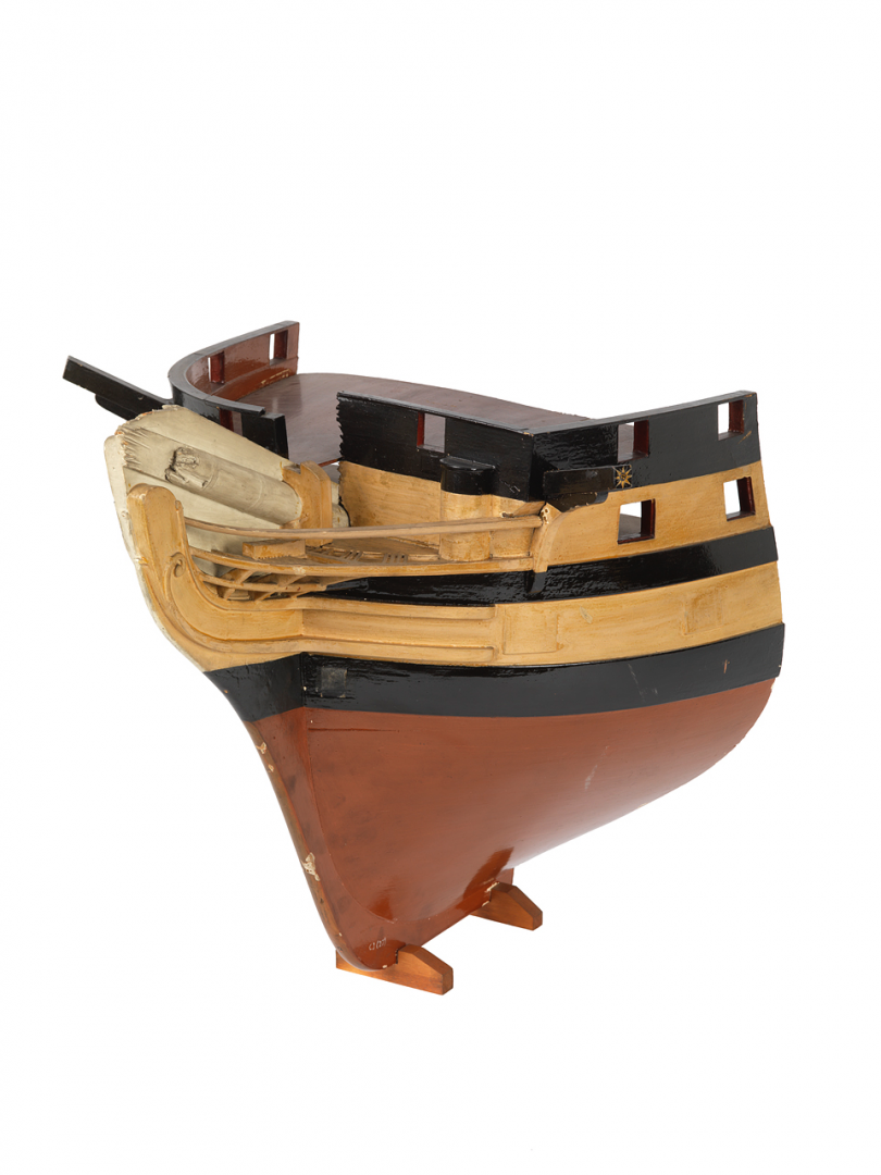
Both the plans as build and from 1788 shoe no difference in height from the deck to the platform of the beakhead bulkhead 🙂 So Heller is good there. This platform was a later introduction in the 3rd rate+. The step in P. was introduced in 1920 when the bow was complöetely reconstructed, eliminating the round bow of 1816. Even though Heller orientated the model on the appearance of 1920-1960 they got this detail and the missing side entrance right! Oh my God they got bashed for that when I started building this kit 😉 XXXDAn
-
48pdr cannon
dafi replied to Thanasis's topic in Discussion for a Ship's Deck Furniture, Guns, boats and other Fittings
On top of it all writing are computer based letters 😉 Oh, I love the look of the low rider scene, my friend has a car like this ... 😆😆😆 XXXDAn -
Carriage Gun Rigging
dafi replied to Dr PR's topic in Discussion for a Ship's Deck Furniture, Guns, boats and other Fittings
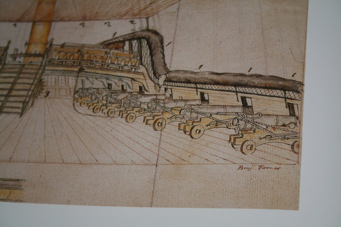
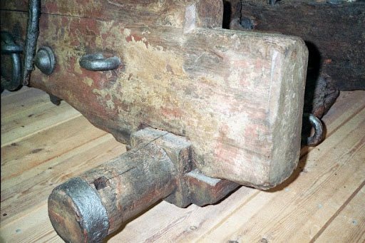
Thank you Morgan, one can nicely see the pair of two holes in the front that could have been used for fixing the horn/breast. What you believe to recognize as horn is in my opinion another wrecked cheek in the background, see the pictures above with the guns on the Euro-pallet. But what was the side cleat for? Keeping the breeching line clear? Keeping clear of hanging knees? XXXDan -
Carriage Gun Rigging
dafi replied to Dr PR's topic in Discussion for a Ship's Deck Furniture, Guns, boats and other Fittings
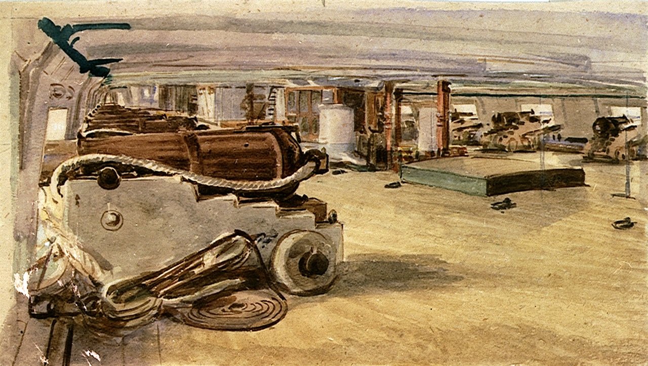
And here a picture I was looking for: HMS Superbe 1842 with possibly double breeching line.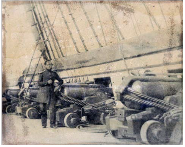
-
Carriage Gun Rigging
dafi replied to Dr PR's topic in Discussion for a Ship's Deck Furniture, Guns, boats and other Fittings
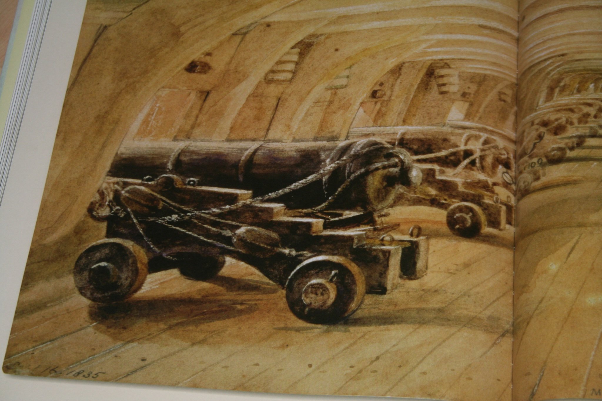
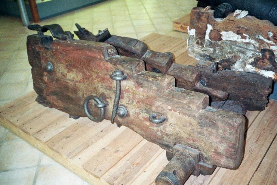
Completely agree 🙂 Just looked at my archive and found two pictures with marks that could come from cleats and checks: Two holes in the front of each carriage´s cheek and some change of color where a cleat could have been on the side. Make up your on mind upon this 🙂
-
Terminology help please: renard de navigation and renard de présence
dafi replied to Sandra's topic in Nautical/Naval History
I think something alike can be found behind the whipstaff of the Batavia.

-
Carriage Gun Rigging
dafi replied to Dr PR's topic in Discussion for a Ship's Deck Furniture, Guns, boats and other Fittings
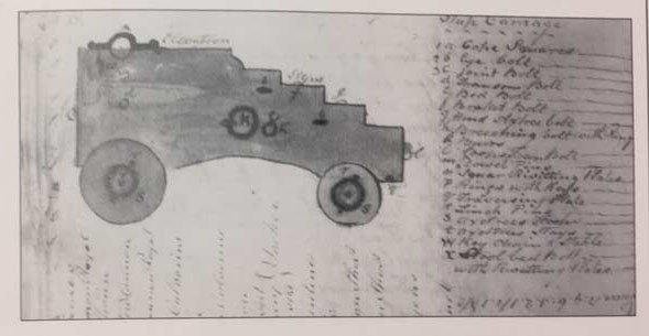
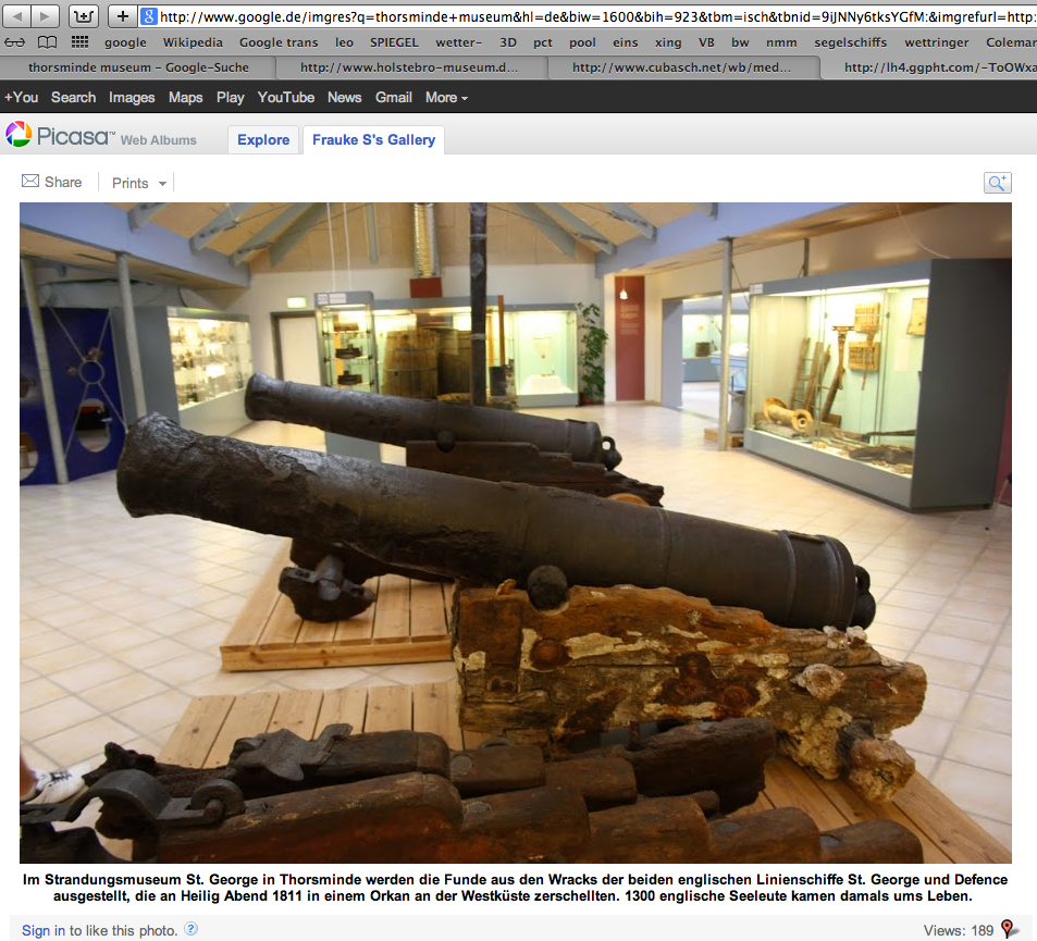
Thank you Alan and Gary. Comparing the drawing of Rivers and the artifact of St. George the position of the bolts is quite the same. Have to look my other pictures for the traces of the cleats. Even though Rivers does not show these, any thoughts about that? Also funny that the St. George carriage appears to have shades of red and ochre. Were they overpainted once? Was there already any research about the color? And another question: What was the iron pin for? What else served the eyebolt that it is stuck in? XXXDAn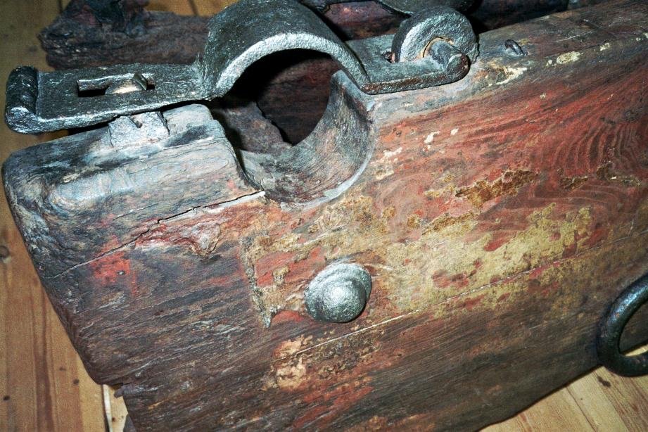
-
Carriage Gun Rigging
dafi replied to Dr PR's topic in Discussion for a Ship's Deck Furniture, Guns, boats and other Fittings
Dear Alan, also thank you for the hint for the 2 eye bolts. It is a reminiscence upon the carriages displayed in Portsmouth 😉 I had a look into my sources. First of all William Rivers Gunner of the Victory does not display these ones 🙂 Also the best hint are always the artifacts, one of the best is Thorsminde St. George, nothing to be seen too 🙂 All other contemporary plans or drawings of 1800 +/- do not show them either. Drawing of the HMS Venerable from NMM. The confusion starts after 1820+, where these eyebolts start appearing in paintings and photographs. Also the french heavy guns had these eyebolts. As seen for the sources approx. 1800 I will omit these bolts confidently on my Victory 🙂 All the best, Daniel