HOLIDAY DONATION DRIVE - SUPPORT MSW - DO YOUR PART TO KEEP THIS GREAT FORUM GOING! (Only 20 donations so far - C'mon guys!)
×


Roger Pellett
-
Posts
4,519 -
Joined
-
Last visited
Content Type
Profiles
Forums
Gallery
Events
Everything posted by Roger Pellett
-
Unlike a lot of movies using models this really looks realistic. Without getting into technical details the viscous effect of the water varies with the size of a floating body. The models used in movies often look that they are traveling in molasses rather than water. Roger
-
Unfortunately it’s an expensive place to get to if you are not driving. Our friends living in major airline markets are astonished at the air fares in and out of Duluth. Otherwise, we have a great selection of places to stay, some really unique conference venues, two and possibly three museum ships, a nice maritime museum and a working waterfront. Roger
- 599 replies
-
- 4
-

-
- sidewheeler
- arabia
- (and 4 more)
-
Does anyone know what Wood species Briar is? Roger
-
I would vote for that too. It’s the mid west’s turn. My first choice would be at the largest port on the Great Lakes- Duluth, Minnesota but since I don’t think that that is going to happen, I would get behind Kansas City. I used to travel there on business and it’s a great city. Roger
- 599 replies
-
- 3
-
-
- sidewheeler
- arabia
- (and 4 more)
-
‘This is from “Standard Designs for Boats of the United States Navy” (1900) by Chief Constructor Phillip Hitchborn, USN For a 14ft Dinghy oars to be either 9ft-0in or 10ft-0in length overall. For a 9 foot oar: blade- 3ft long x 5-3/8in wide at the tip loom dia at leather- 2-1/8in handle- 5in Long x 1/3/8in dia The loom tapers to 1-3/8in at the junction with the blade. The blade is 1/2 in thick at the tip. My information from Steele was taken from information printed in the NRJ and is now filed away. I’ll try to find it tomorrow. Roger
-
Rules for Oarmaking are published in Steele. These include a table for length based in boat size. Roger
-
Homemade Spray Booth
Roger Pellett replied to BETAQDAVE's topic in Modeling tools and Workshop Equipment
Dave, A nice project! I am concerned with your fan if you plan to use solvent based paints as it does not appear to be explosion proof. Roger -
Mike, I have a Badger 350 airbrush powered by an air compressor. The Badger is a well made rugged inexpensive unit that is easy to keep clean. With it I have been able to produce acceptable paint jobs on wooden models. My last model was painted exclusively with acrylic paints mixed from artists acrylics. You will be frustrated without an easy to use dependable air source. My first efforts many years ago were with canned air. I then rigged up an air system by hooking various components to an ancient farm air compressor. A couple of years ago I scrapped my system for a compact air compressor/ tank combination bought at a big box home improvement store. This is equipped with a pressure switch that stores air in the tank at 125psi. Downstream is an adjustable regulator to limit pressure to the air brush. THIS IS IMPORTANT! The Badger air brush body is cast resin. The air inlet is a brass fitting pressed into the resin body. If the air brush is over pressured, the fitting can be blown out of the body and it’s time to buy a new one. Your air brush budget should definitely include purchase of one of these integrated compressor with built in adjustable regulator. Roger
-
Glen, Beautiful work on the steam plant. Minirature marine engineering! I reread the chapter about the Charleston attack in Rowanna Reed’s book last night. The timing of Wells’ letter that you quote would indicate that he was telling DuPont, “Either you use the ironclads or I’ll send them to someone who will.” Roger
-
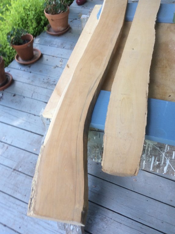
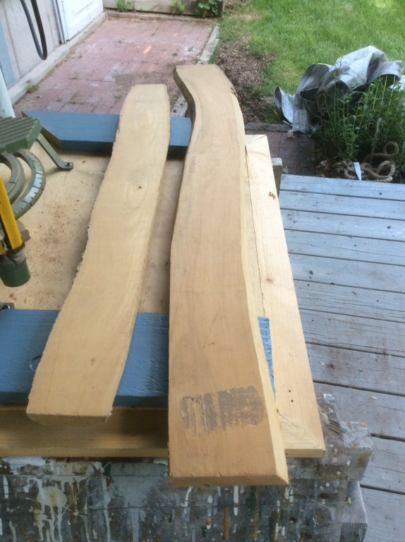
It looks like I got some of the same stuff that you did. I bought mine from a supplier in Baltimore in the mid 70’s too. I do not know the exact species but it is sure nice stuff to work with. I should probably either tackle some large project to use it up or include it in my will, otherwise when I am gone it will end up in someone’s fireplace! Roger
-
Here are two pieces of Boxwood, not Costello Boxwood. The wood is yellowish in color, and quite heavy. The grain is very tight, and when cut holds a clean, crisp edge. When sanded with fine grit it takes on a nice polish. I find it to be more brittle than either pear or holly. Roger
-
Yes, that’s right I didn’t think of it in that context, and it would have been 1863 as in April of 1862 there was only one monitor, the original one. The Western Gulf Squadron was responsible for waters from Pensecola, Florida to the Rio Grande River. It’s headquarters were in New Orleans. By the fall of 1863 there were only three major ports connected to the South’s rail network not either captured outright or sealed up- Charleston, Wilmington, NC and Mobile and the idea was to attack Mobile after Charleston. In the event, this didn’t happen as the Passaic Class Monitors remained at Charleston, and the Mobile attack was delayed into 1864 when the Canocus Class Monitors became available.
-
Glen, in your historical analysis above, did you mean to say that after the Charleston attack, the Ironclads were to be sent to Mobile (rather than New Orleans)? By the time that Charleston was attacked New Orleans had been under Union control for over a year. Most historians fail to realize that the Monitor class of warships and Keokuk were designed to counter the Confederate ironclads being built, and that they lacked offensive power to engage forts. The Passaic class monitor Weehawken demonstrated the ability of the monitors to do what they were designed for by convincingly defeating the ironclad Atlanta. Unfortunately Keokuk never got the chance to do so. In attacking Charleston, the Union Navy erred in not placing its vessel with the most offensive capacity- New Ironsides,in a better position to attack the forts. In her excellent book Combined Operations in the Civil War, author Rowanna Reed makes this point. Roger
-
Learned this the hard way!! In finishing your baseboard to minimize warpage you have to “balance” it. Whatever you do to the top surface, do to the bottom. You therefore need to seal both the top and bottom against moisture. My personal opinion is that this ship would not have been heavily weathered in service. The ship was a prestigious command, with a large crew to keep busy when not in action. Like the old navy expression goes “If it doesn’t move, paint it.” And remember, a warship was judged by the condition of its boats. I am enjoying your posts. I am not a plastic modeler and am amazed at the detail that you guys are able to incorporate into these small scale models. Nice work! Roger
-
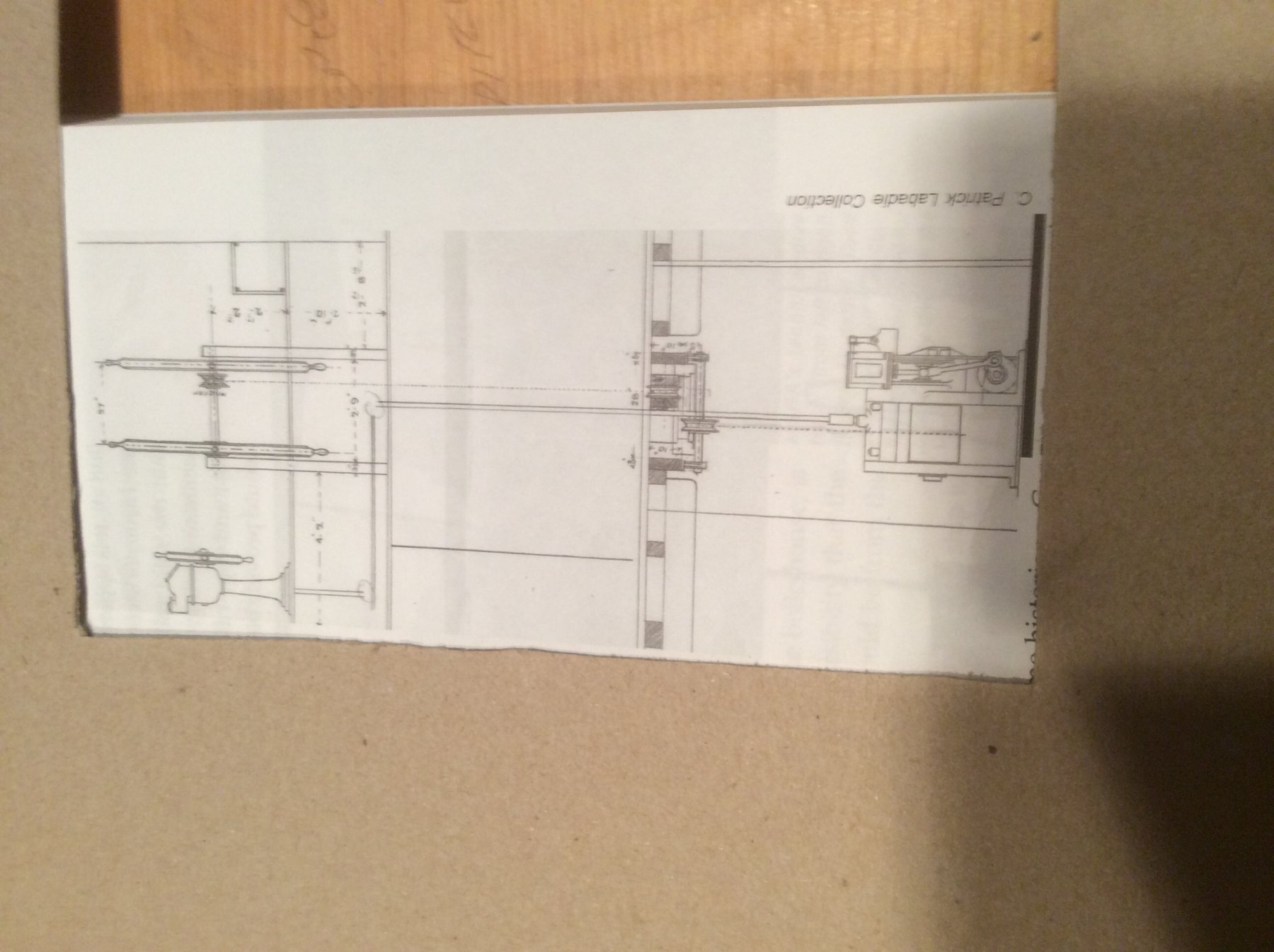
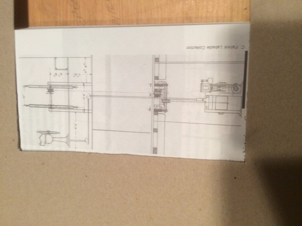
No, I think more likely like the drawing below. In this case there were three wheels in the pilot house of this vessel. The smaller metal wheel operated the steering engine below while the double wooden wheels could be used to steer the ship manually. Sorry, my IPad insists on turning the picture on its side. Roger
-
All wooden wheels were also used on some Great Lakes steamships. By the 1890’s these vessels were often steered with steam steering engines- little more than winches that drove steering chains running back to the rudder quadrant in the stern. The wheel was just required to open and close valves on the winches. This is important because this wheel looks to be too lightly built to stand up to forces from hand steering a sailing vessel. Also by the second half of the Nineteenth Century cast metal steering wheels were readily available and widely used on sailing vessels. This does not make this artifact any less interesting. Roger
-
I agree with Bob’s post above. The underwater Archeology people have published a lot of new information since this book was published and much of it can be found on the internet. The bad news is how much is still unknown. In most cases information is limited to mast steps, floor timbers, and many a few first futtocks. Virtually nothing exists for upper works. It would be even be impossible to determine which of these vessels, were fitted with square transom or round sterns. The Newport Ship currently being conserved in Bristol, UK is one of the “better preserved” examples of a ship of this period, probably built in Spain. The reconstruction is based on a remarkably small fragment of the hull with the rest, such as the square transom inferred. Roger
-
Keith, Have you ever visited Isle Royal National Park? It’s the large island on Western Lake Superior. Accessible only by boat, it gets about 35,000 visitors a year. Roger
- 238 replies
-
- 3
-
-
- leviathan
- troop ship
- (and 2 more)
-
The basis for any good model is a good set of lines that define the vessel’s hull. Rigs could and did change to suit circumstances. Chapelle’s Baltimore Clippers Book was originally copyrighted in 1030 so it is one of his early works. Many of the drawings reproduced in it the were traced from takeoffs of hull lines for vessels acquired by the Royal Navy. This book also includes copies of drawings redrawn from those produced by the French Naval constructor Marestier who visited the US in 1820. I don’t know of a better source of information for these vessels unless you are willing to travel overseas. My copy of the book book was printed by Tradition Press in 1965. It is about 11in by 8in so the drawings show up well. I believe that copies of this same edition are available. If you want a later source I recommend Chapelle’s “Search for Speed Under Sail,” but my copy of the Baltimore Clipper produces the material in a larger format. Roger
-
Buy a used copy of “The Baltimore Clipper” by Howard I Chapelle. The book is loaded with plans. You should be able to buy a good used copy for less than $10. Niagara is not representative of vessels usually classed as hermaphrodite brigs. She was a true brig. In addition, any drawings that would be available would be for one of several reconstructions attempted over the years including the one presently sailing on the Lakes. In other words they do not depict a real vessel from the early 1800’s. All of the drawings in Chapelle’s book are based in authentic drawings or half models. Roger
-
Very nice work! Roger
-
That is why it is helpful to make up a table of rigging sizes ahead of time. With an Excel spread sheet you can add a factor to each column and work your way across to the final scale diameter. I made a simple stepped gage from two sizes of dowel with marks at 1/8” and 1/4”. For example, the diameter of line where 10 wraps touches the 1/4” Mark is .25”/10 or .025”. Each available spool of line is marked with the number of turns per 1/4”, and the last column on my rigging table is also tabulated in the same way so at my workbench it is simply a question of using the spool marked with the correct number of turns. Roger
-
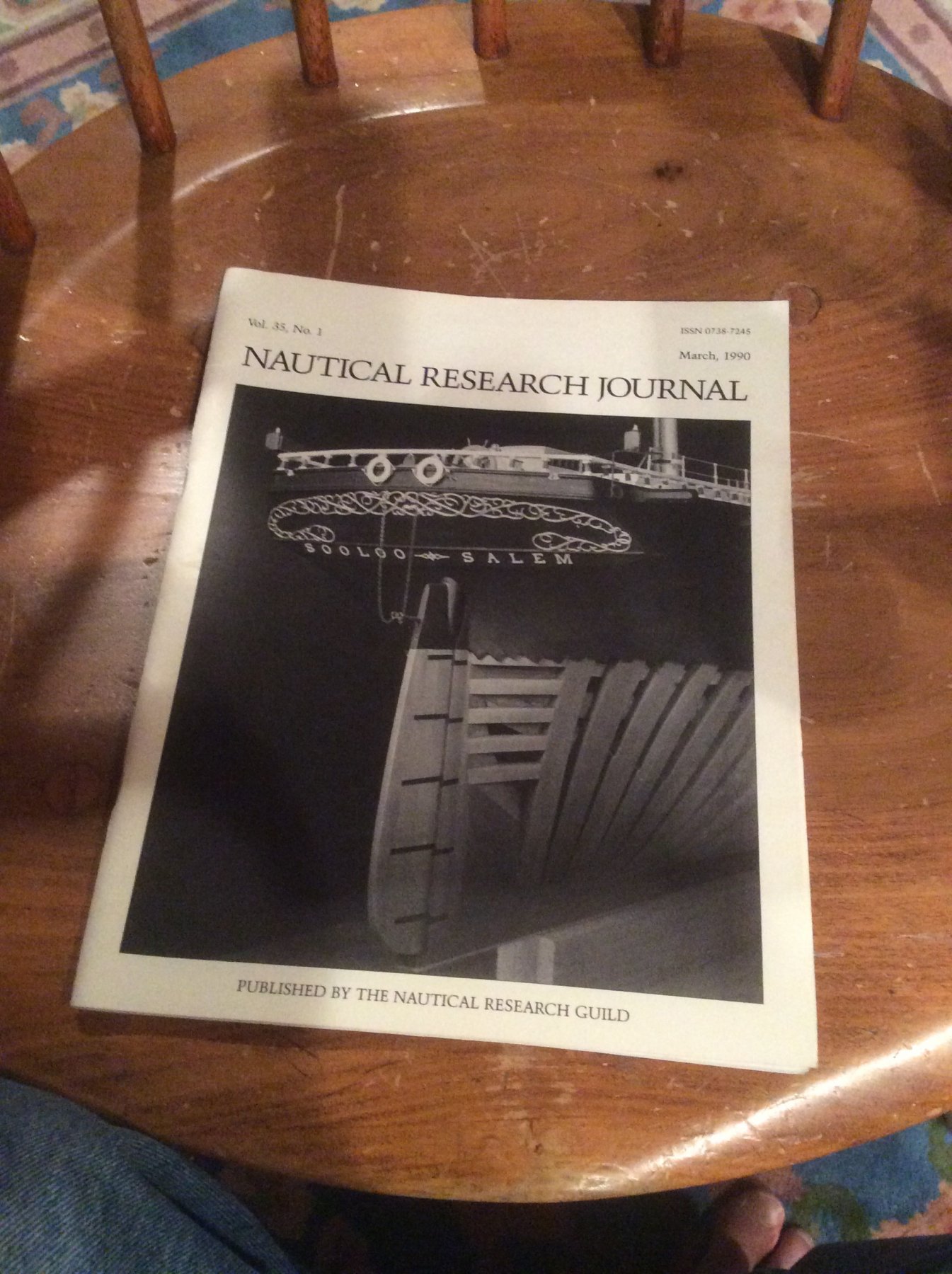
Keith, In 1990, master modeler Rob Napier published a series of articles in the Nautical Research Journal detailing techniques that he used to build a highly detailed model of the sailing vessel Sooloo. The model had quite a bit of scroll work like you are faced with. If my memory is correct, he started with a flat photo etched part that he “built up” with solder, then filed to its half oval cross section. A variation of druxey’s suggestion. I believe that you will find a description of his process in either No’s 2 or 3 of Volume 35. Roger