HOLIDAY DONATION DRIVE - SUPPORT MSW - DO YOUR PART TO KEEP THIS GREAT FORUM GOING! (Only 72 donations so far out of 49,000 members - Can we at least get 100? C'mon guys!)
×


Roger Pellett
-
Posts
4,519 -
Joined
-
Last visited
Content Type
Profiles
Forums
Gallery
Events
Everything posted by Roger Pellett
-
Die Kogge Von Bremen by kentyler
Roger Pellett replied to kentyler's topic in - Subjects built Up to and including 1500 AD
The lines on the left hand side of the drawing posted above are the diagonals, not buttocks, Roger -
Welcome, from another former Buckeye.
-
Die Kogge Von Bremen by kentyler
Roger Pellett replied to kentyler's topic in - Subjects built Up to and including 1500 AD
Patrick, What are the plans for the “ Antwerp Cog”? Will it be reassembled and displayed? Roger -
Eric, How did you anneal the rod? To anneal steel you need to cool it slowly. When I have tried to do this it air cools so rapidly that it remains hard.
-
The problems of ballasting merchant ships were different from those with warships. The ballast in warships was semi permanent as it would remain in place until being discharged at the end of a commission or in some cases when the ship was careened on a distant station. Merchant ship’s arriving at a loading port “in ballast” on the other hand would need to discharge all or some of this ballast before loading cargo. This is was a time consuming operation that increased the vessel’s operating expenses. Particularly hard hit were sailing vessels engaged in supplying the city of London with coal. These were short voyages and there was no back haul cargo so ballast had to be discharged each time the vessel reached the N.E. English coal loading port. In the mid 1800’s a Lloyd’s surveyor named McIntyre patented the idea of building watertight iron ballast tanks on top of the floor timbers in the wooden colliers sailing in the London coal trades. This meant that water ballast could be quickly discharged upon arrival and that laborers would not have to be paid to dig out ballast. When the first iron and later steel colliers were built ship owners and naval architects duplicated wooden shipbuilding practice by building McIntyre ballast tanks on top of the iron or steel transverse floors. Towards the end of the 1800’s they improved this design by simply plating over the floors and using the “double bottom” to hold water ballast, a design that is still used today. Roger
-
That the guys that built these were able to create anything resembling a ship is amazing. They worked in primitive conditions with hand tools, and inadequate lighting. If their results look crude by today’s standards that understandable.
- 95 replies
-
- 7
-

-
- POW
- Bone model
- (and 2 more)
-
I have a Proxxon pen sander. It is hooked up to a MinCraft 12v variable speed power supply. I don’t use it often but there are times when it will work better than anything else. First of all, the long dimension of the tool is perpendicular to the action of the sanding head. This means that it works well in confined spaces like the areas between frames in an open boat. Holding it like a pen gives precise control. The tool comes with several plastic “feet” that hold the sandpaper attached with pressure sensitive adhesive. I sometimes make shaped shoes from wood that are glued to the feet to sand different contours.
-
A somewhat prejudiced opinion concerning Question No 2. In real life, “skeleton” built ships and boats achieve their shape by supporting planking with closely spaced frames. The frames in a large Royal Navy ship’s boat would be be spaced about 18in apart. The popular European POB kits DO NOT REFLECT FULL SIZED PRACTICES. The widely spaced bulkheads built on a central spine are more akin to the old balsa/tissue model airplane kits. In the worst case, these do not properly support the planking causing areas of unfairness; lumps and flat spots Roger
-
This is a true canoe story, and depending on what you plan to do with your canoe, a cautionary tale. A friend of mine was duck hunting from a canoe on one of our large Northern Minnesota lakes. He was paddling solo and was using a brand new expensive Baretta Automatic Shotgun. He shot at a duck, lost his bearing and found himself in the water alongside a swamped canoe. The lake was shallow enough that he could stand up but when he tried to empty the canoe it kept flooding. After shooting at the duck, the gun then automatically reloaded and in capsizing he had inadvertently squeezed the trigger and blown a hole in the bottom of the canoe. To make matters worse, after shooting the canoe, the gun would have automatically chambered another round! The loaded gun is still on the bottom of the lake. Roger
- 299 replies
-
- 12
-
-

-
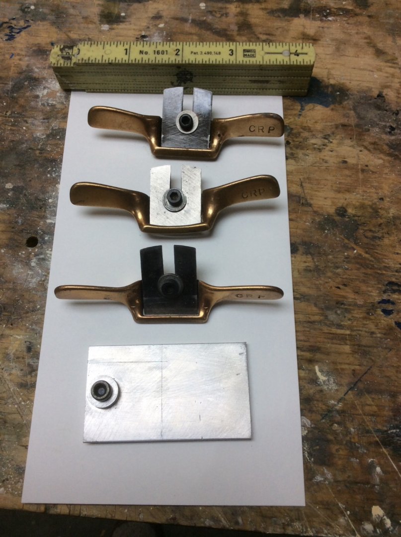
Bob, My spokeshaves were bought 55 years ago. The professional model makers that built wooden models for the University of Michigan’s Naval Architecture towing tank used them. Three of us were building a model to be towed for our senior design project so we each bought a set. I later replaced the slotted screws with the socket headed cap screws screws to make the blades easier to tighten. The aluminum plate is home made and allows the two straight blades to fit into my sharpening guide at the proper angle. Otherwise, the blades are too short.
-
The definition of stress, is force divided by area. In my world it is pounds per square inch. This definition applies to stress acting in any direction; compressive, tensile, bending, shear, torsion, etc. The actual failure mechanism is much harder to define, especially as there is often more than one type of stress acting simultaneously in any given situation. For example the double planking in a POB model is subject to bending stresses due to the curvature of the hull. Simultaneously there is also a shear stress acting parallel to the length of the planking between the two layers. Shear stresses along the longitudinal axis are what cause beams (planking) to resist bending. Roger
-
Not exactly answering your exact question but I like using these small spokeshaves to shape solid hull models
-
Many years ago I built a glued lapstrake canoe that looked remarkably like your Sassafras. It was designed by a guy named Tom Hill who published plans in his book Ultralight Boatbuilding. Instead of using expensive Occume plywood I used cheap Luan floor underlay plywood. This technique is true lapstrake boatbuilding with lapped seams glued with epoxy instead of clench nailed. Like you I covered the two bottom planks with fiberglass. The rest of the hull I just painted with 2-3 coats of quality marine paint. The hull was plenty strong and the canoe got plenty of use. I don’t think that the epoxy resin adds strength. When used in conjunction with cloth, it is the cloth that adds the strength.
-
I agree about the amine blush. Epoxy also does not hold up well to UV light. If you intend to leave the hull with a bright finish the final coat should be a UV inhibited marine varnish. I don’t understand why the clear coating with epoxy is necessary. I would just use multiple coats of a quality marine varnish.
-
I recently posted an experience that I had with CA that resulted in a trip to the local emergency room. It’s in the Shore Leave “What did you do today thread.” I agree with Bob. It’s the Devil’s Spittle.”
-
Re: Wefalk’s post #12 above regarding growth rate & wood density. An outlier would appear to be the Lilac bushes that grow behind my house. These grow like weeds and require pruning every two or three years to keep them under control. The last time that they were pruned I saved some of the larger branches. The wood is hard, dense, with no noticeable grain. Roger
-
Before buying more wood, do some research to determine a realistic sail plan for your model; not what the kit designer thought looked good. Some of these longboat rigs had quite short gaffs.

-
With apologies to Kipling, “You’re a better man than me, Daniel Pariser.” Working on a historically significant artifact that belongs to someone else, now that’s scary, but based on your other work I’m sure you’ll come through with flying colors! Roger
- 95 replies
-
- 5
-
-
- POW
- Bone model
- (and 2 more)
-
Steven, Not exactly in the spirit of an ancient ship, but how about molding these in resin? You could carve a piece of wood to the correct triangular shape. Then put mold material Bondo? In a frame and use the end of the wooden triangle to make indentations. Then fill each indentation with resin.
- 740 replies
-
- 3
-
-
- Tudor
- restoration
- (and 4 more)
-
Can you identify this feature? 19th century 1st Rates
Roger Pellett replied to Martocticvs's topic in Nautical/Naval History
Form follows function. With all of that reinforcement, that must be somehow associated with mooring lines or anchor handling. It’s too small for a gunport. -
Personally, I don’t like the seasick green (polite term) color that you wound up with. I’d use paint stripper scraped down with a single edged razor blade. I’d test out your new stain on some scrap first.
-
Robby, yes, decks are cambered but if you are referring to the body plan that you posted the horizontal curved line at the top is not deck camber. It is the projection of the bow of the ship which rises as it approaches the stem.
- 10 replies
-
- 2
-
-
- Packet Ship
- William Webb
- (and 1 more)
-
Robby, If this is to work, buy a plastic French Curve sold at any store that sells office, artist, or drafting supplies. You might also find one at stores like Wall Mart or Target. Naval Architects use special ships curves often called Copenhagen Curves. These are expensive but a more common French Curve should cost less than a cup of coffee. Instead of trying to trace these body plan sections freehand use your straightedge and the French Curve..
- 10 replies
-
- 2
-
-
- Packet Ship
- William Webb
- (and 1 more)