


aydingocer
-
Posts
898 -
Joined
-
Last visited
Content Type
Profiles
Forums
Gallery
Events
Posts posted by aydingocer
-
-
-
Thank you for the great review.
I have bought the tram kit and cannot wait to start building it. However as someone who lived several years in Istanbul in the past, the only thing that discourages me from building this diorama (other than the misspelled KAPALICARSI text, which can be corrected), is the fact that this beautiful nostalgic tram, which is operating between TAKSIM and TUNEL districts (as indicated on the model), does not travel via the Grand Bazaar at all 🙂. It operates back and forth on Istiklal Street which is 2-3km long.
Other than this reality check fail, it seems like a beautiful background to the tram and it can be excused for the sake of combining two attractions of the city 🙂.
- Rik Thistle, mtaylor, Keith Black and 4 others
-
 7
7
-
21 minutes ago, ragove said:
i received my building slip a couple days ago. I will depend heavily on this build log. Aydingocer's photos are much clearer than the directions.
Good luck with the build and remember to check a few posts above by seahorse where one of my mistakes in the build has been addressed.
Regards,
Aydin
-
9 hours ago, philly777 said:
Could you please advise if this will work for ships with the keel length more than 100cm?
According to the manufacturer's specs max keel length is 100cm but there may be a degree of tolerance, though I doubt it will work with keels significantly longer than that.
Specs: http://www.hobbyzone.pl/en/boat-building-tools/26-professional-building-slip.html
-
9 minutes ago, Nirvana said:
Aydin,
That model deserves a special place as for display.
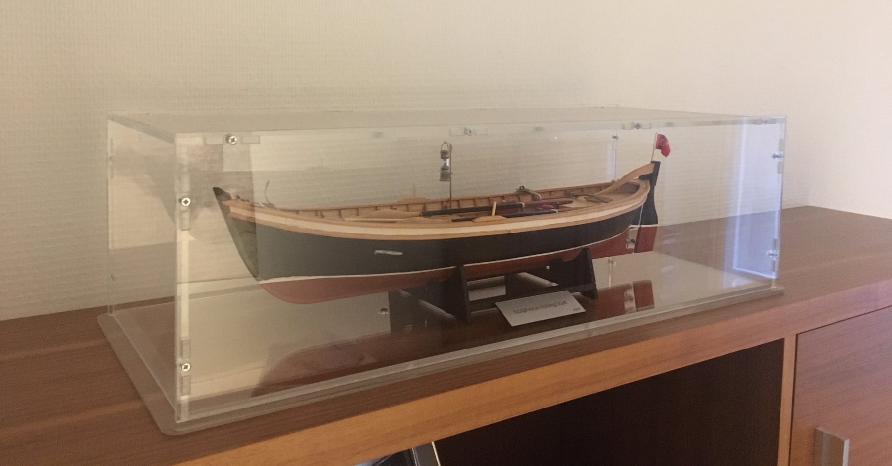
Hope you a case for her and location.
Beautiful work !
Hi Per!
Having said that, it is already in its display case (see image) :). By the way, I strongly recommend this German shop at http://www.sora-shop.com, which manufactures custom made assemble-it-yourself display cases at a very good price and accuracy.
BR;
Aydin

-
-
-
-
-
-
-
-
-
-
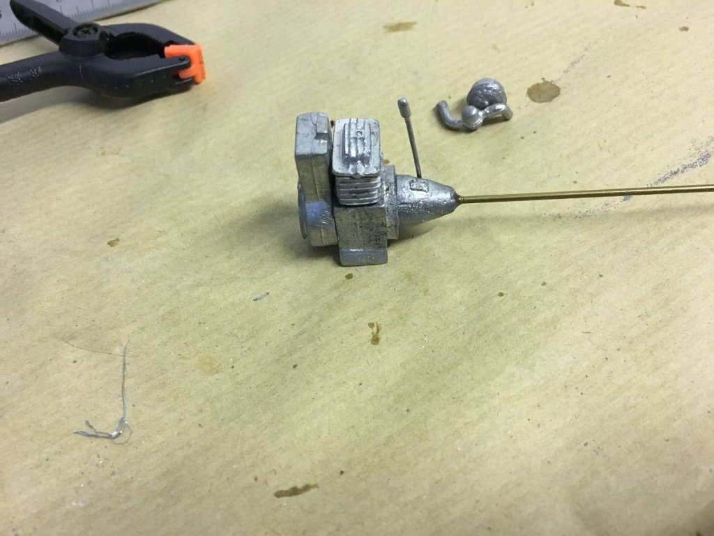
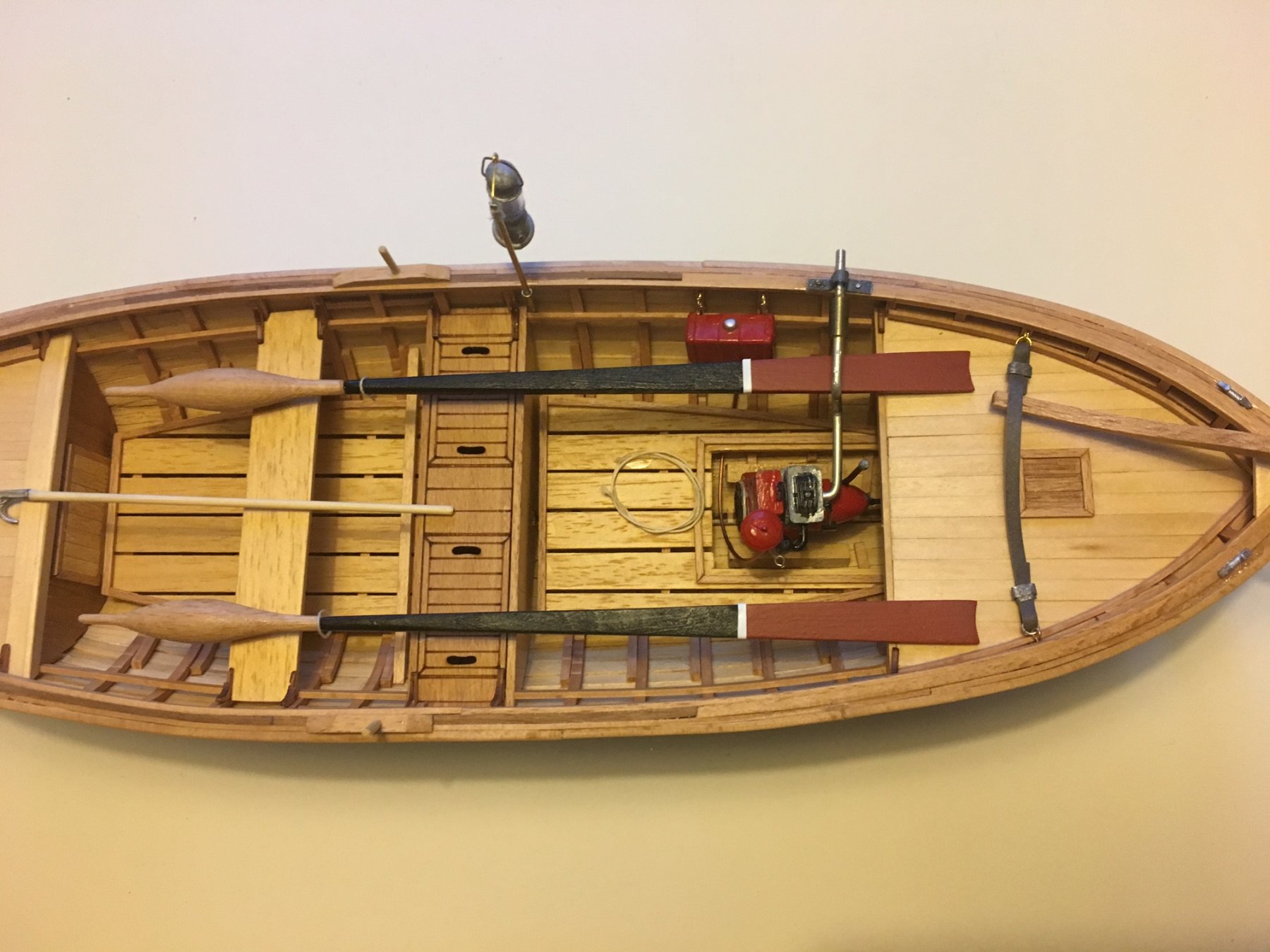
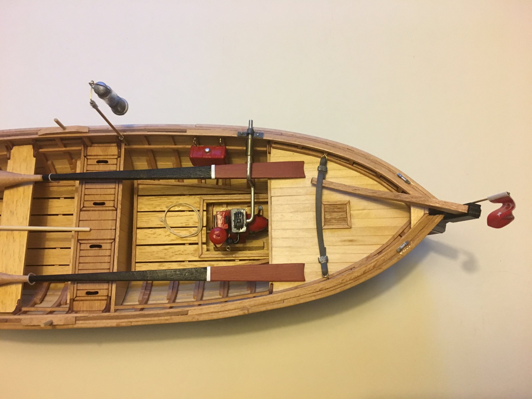
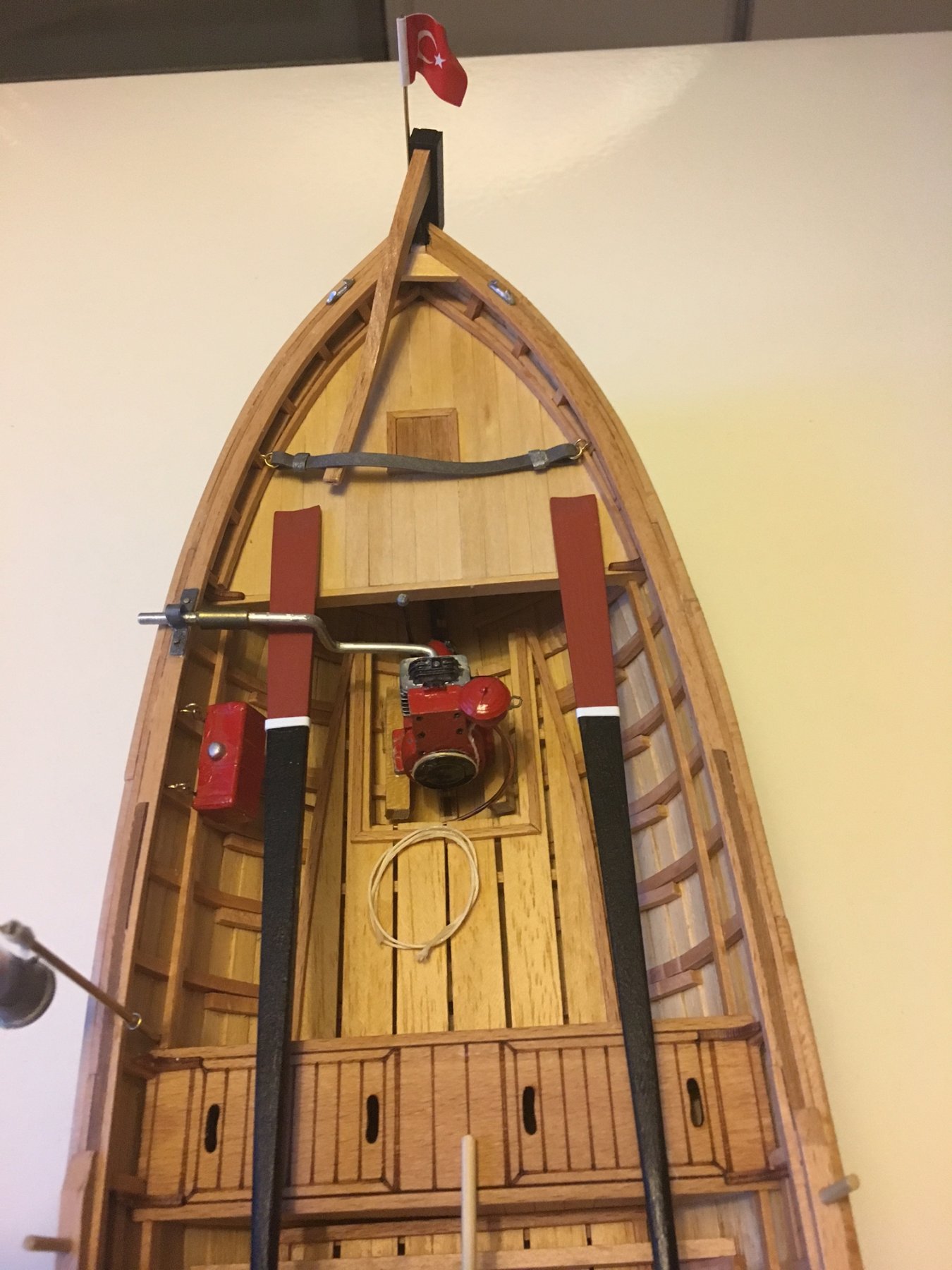
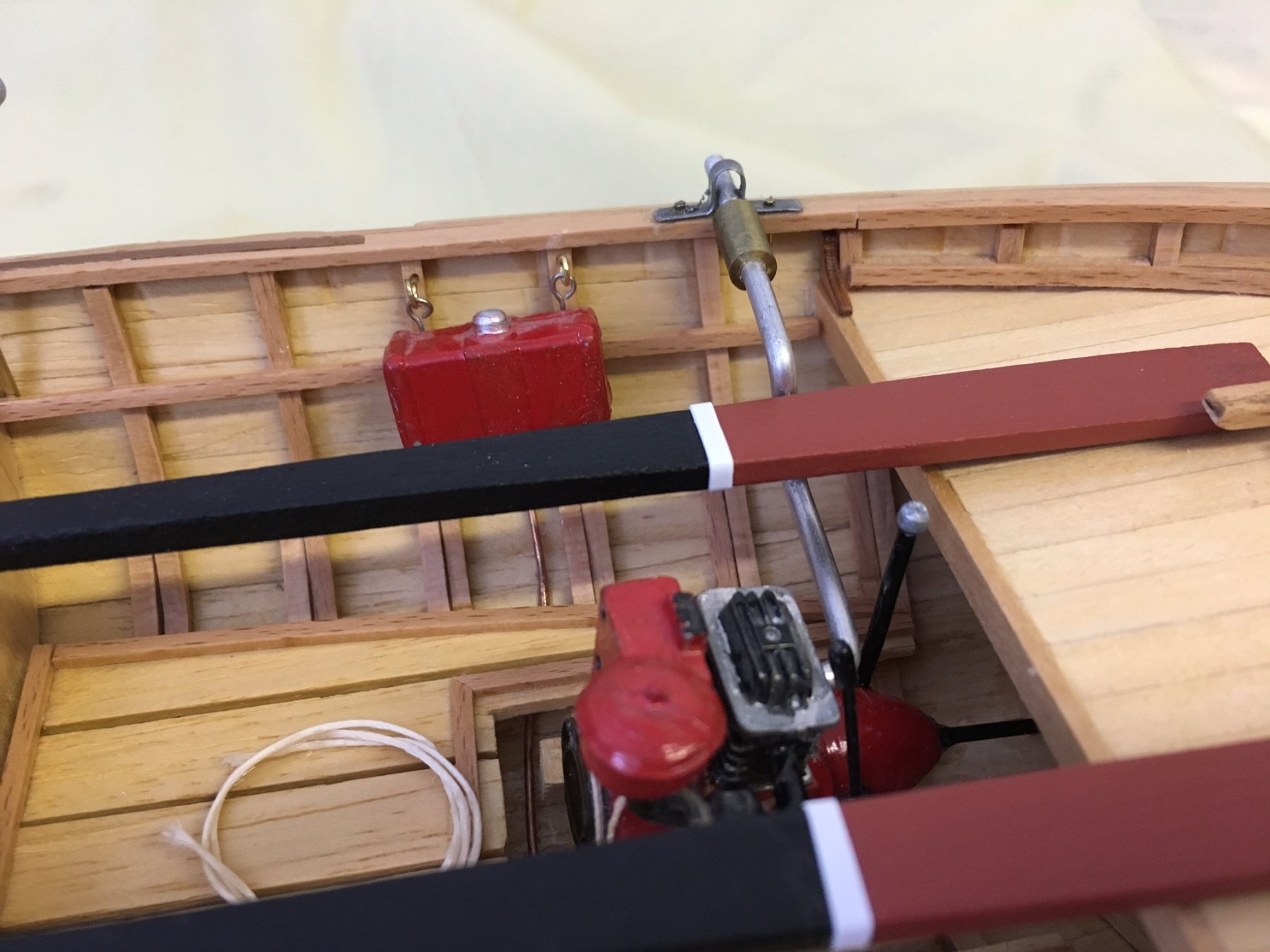
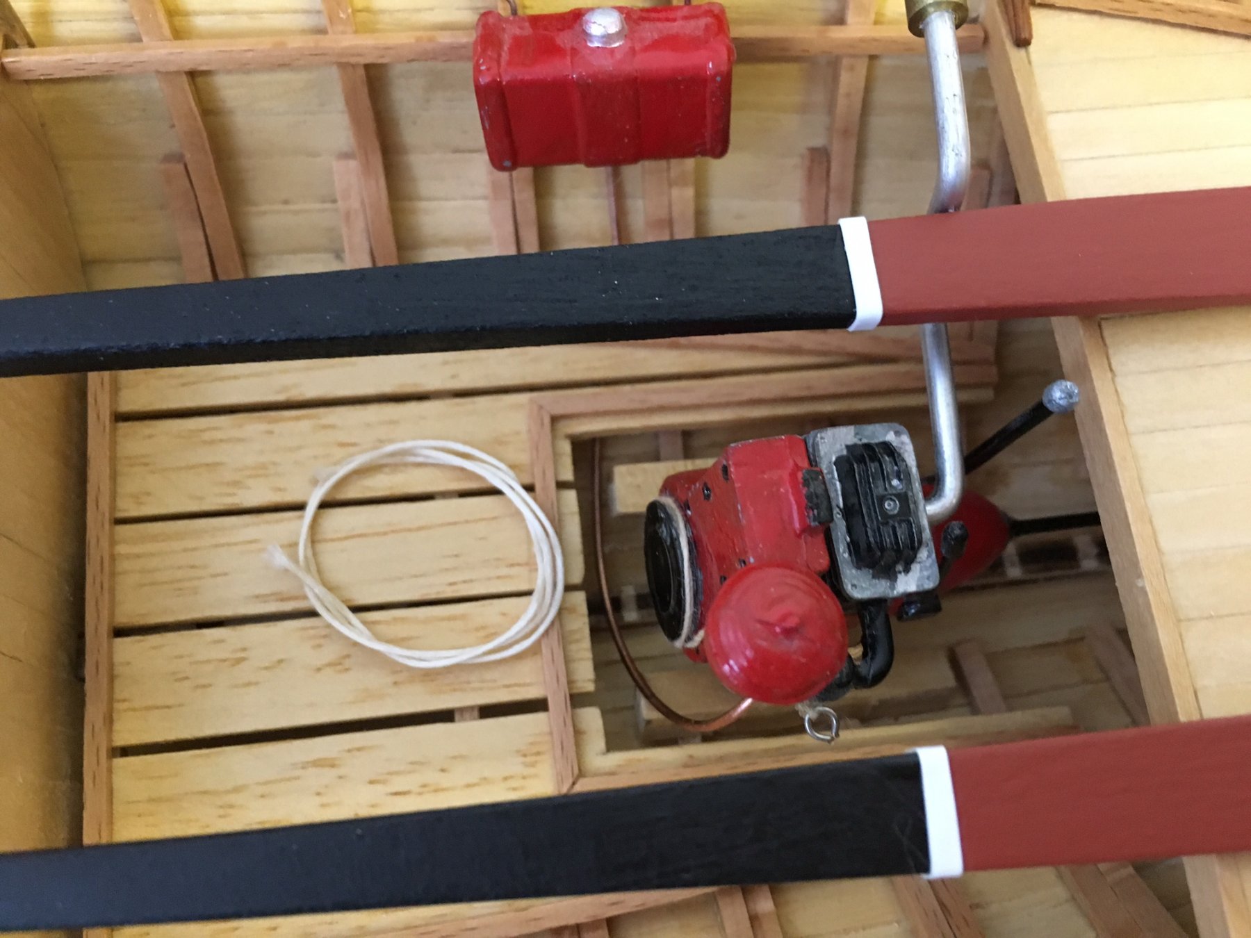
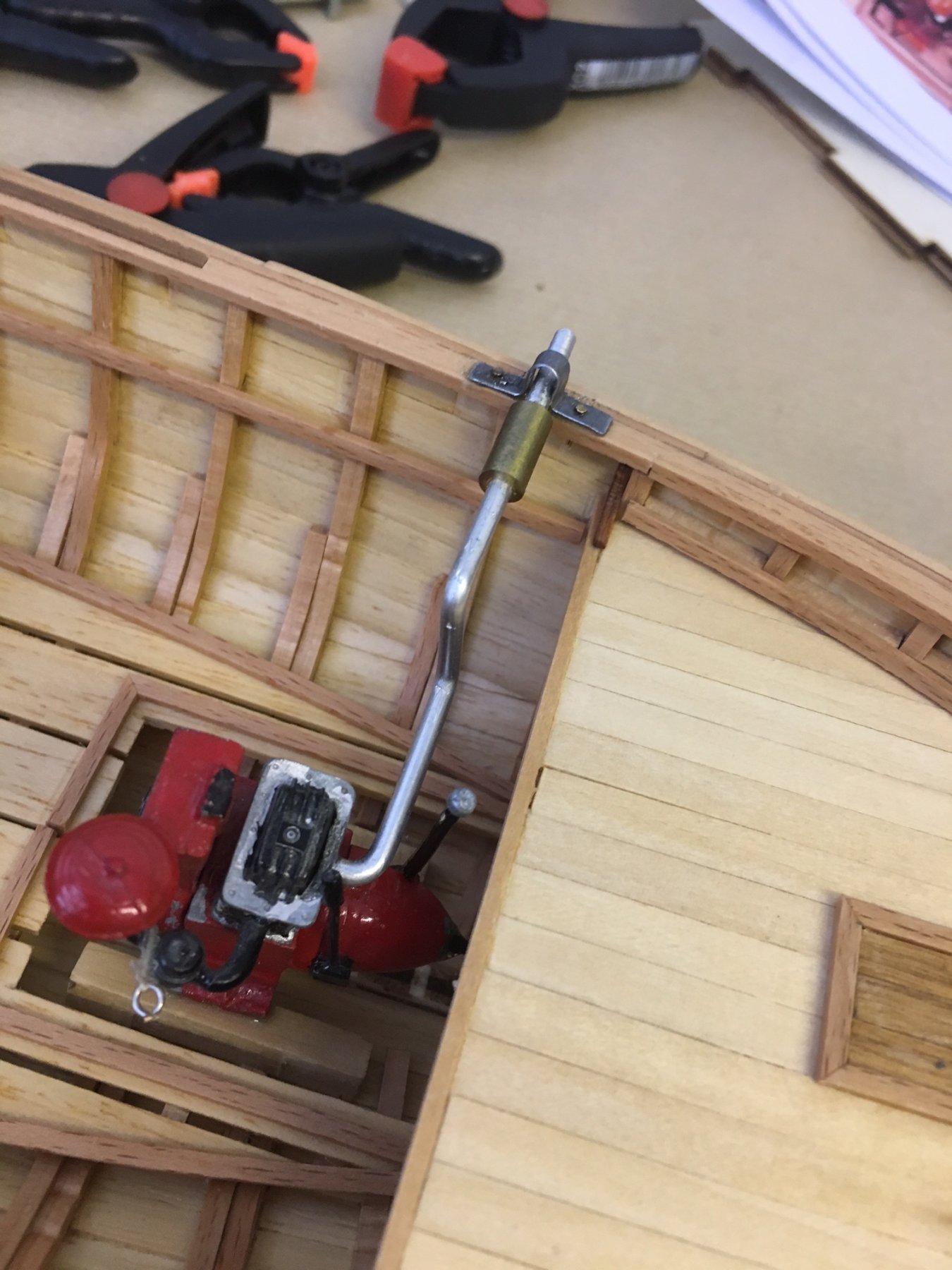
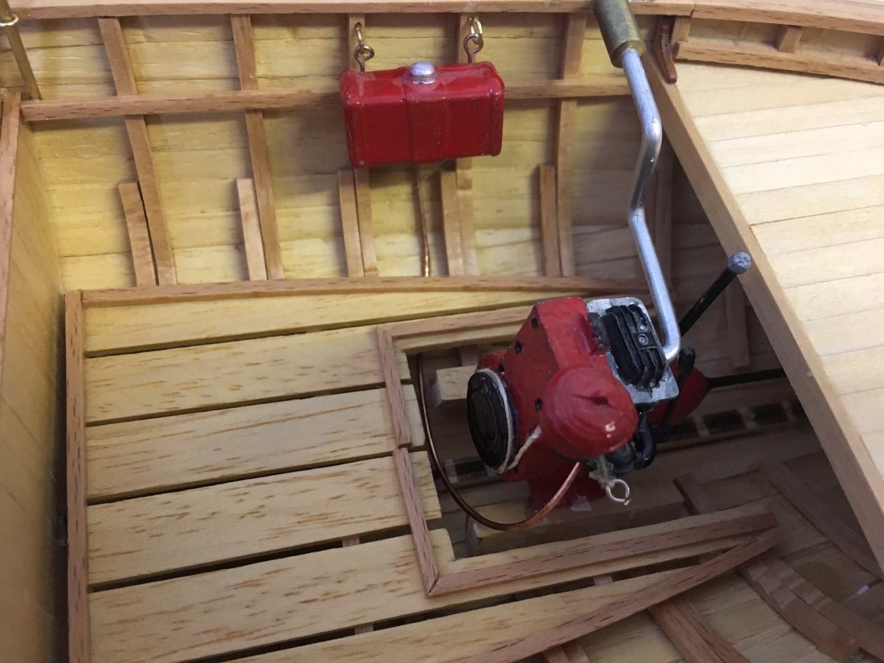
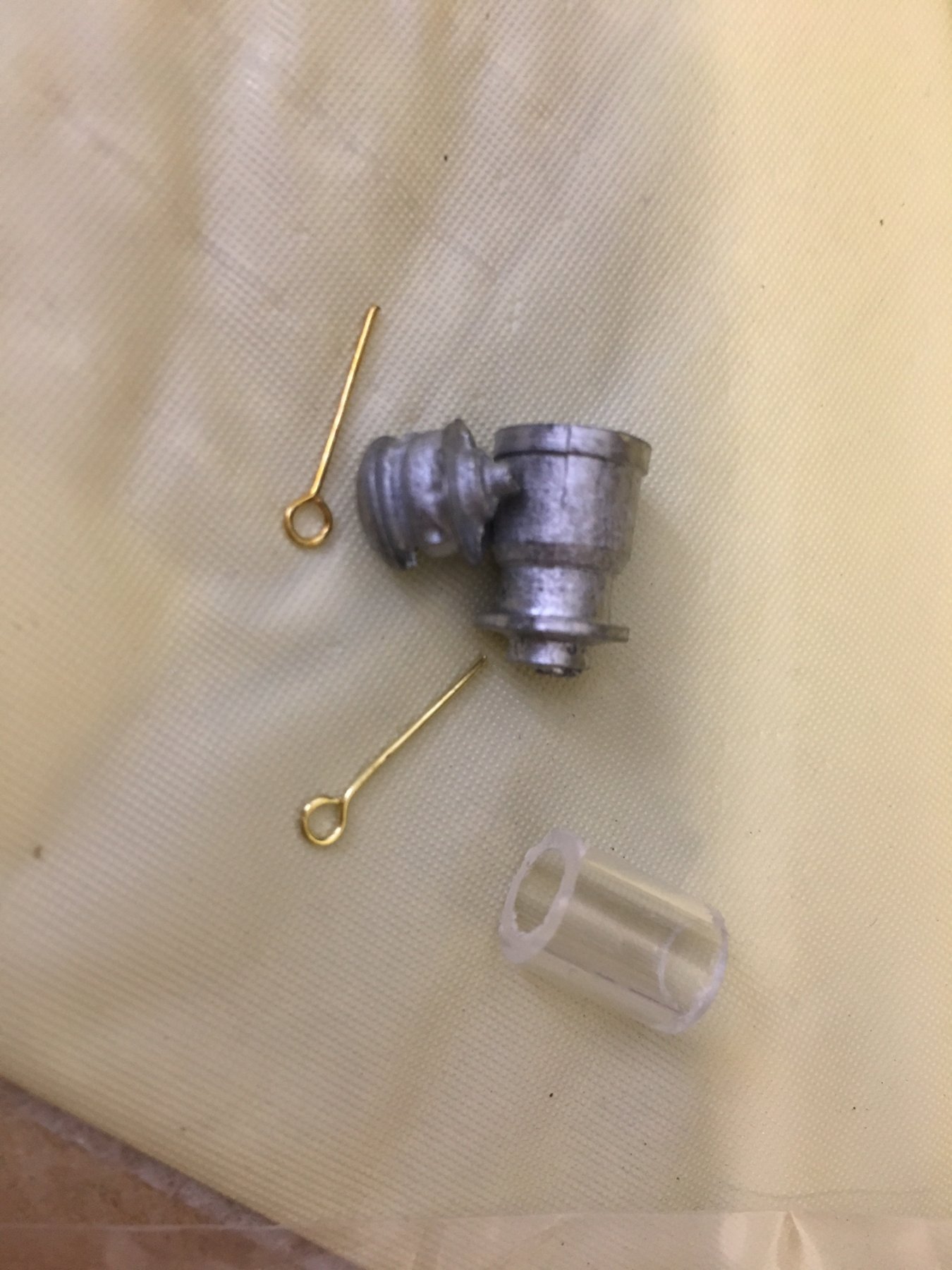
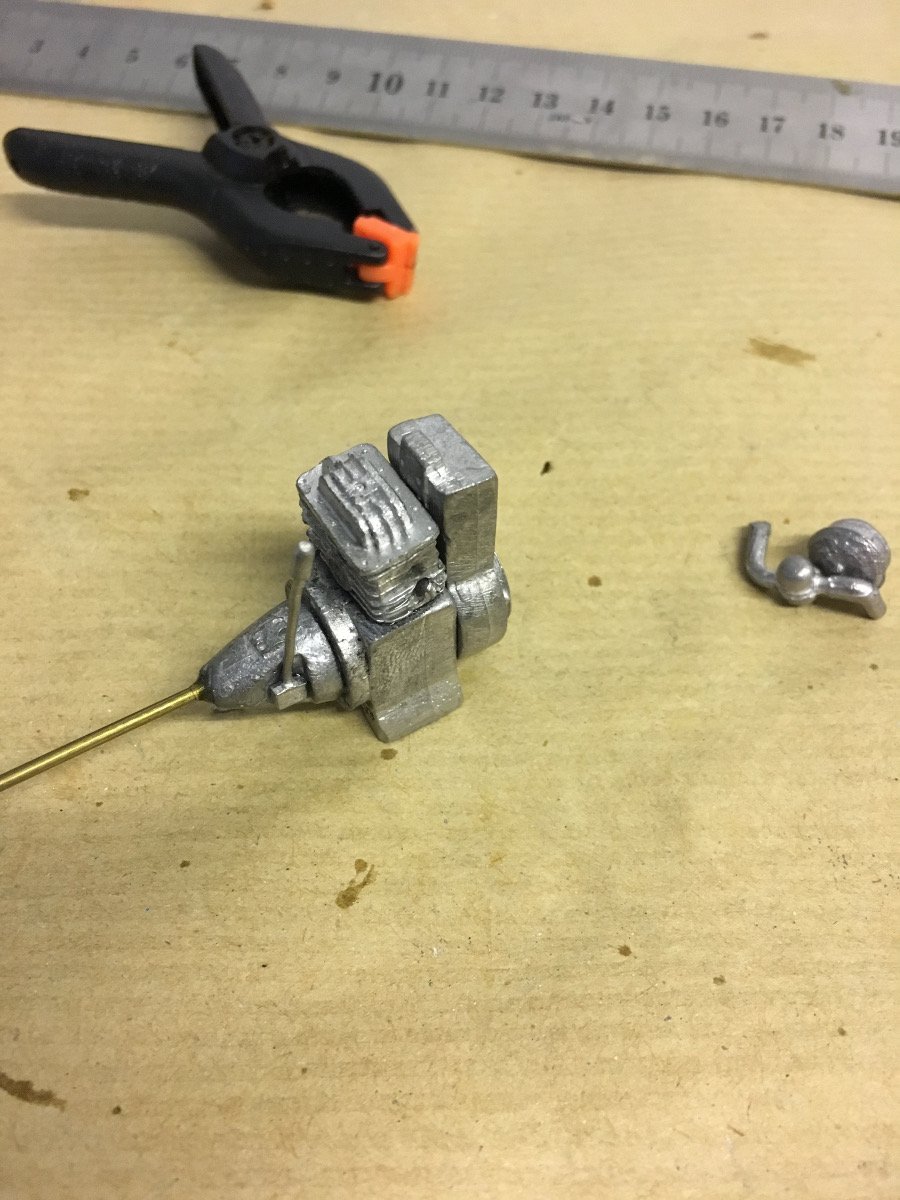
ENGINE, EXHAUST PIPE AND GAS TANK
Exhaust pipe is fixed to handrails using a metal plate. Gas tank is in fact a canister hanging on the side (Note the copper wire resembling the gas input pipe from the canister to the engine)


- John Allen, mtbediz and hexnut
-
3
-
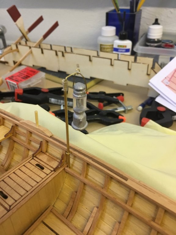
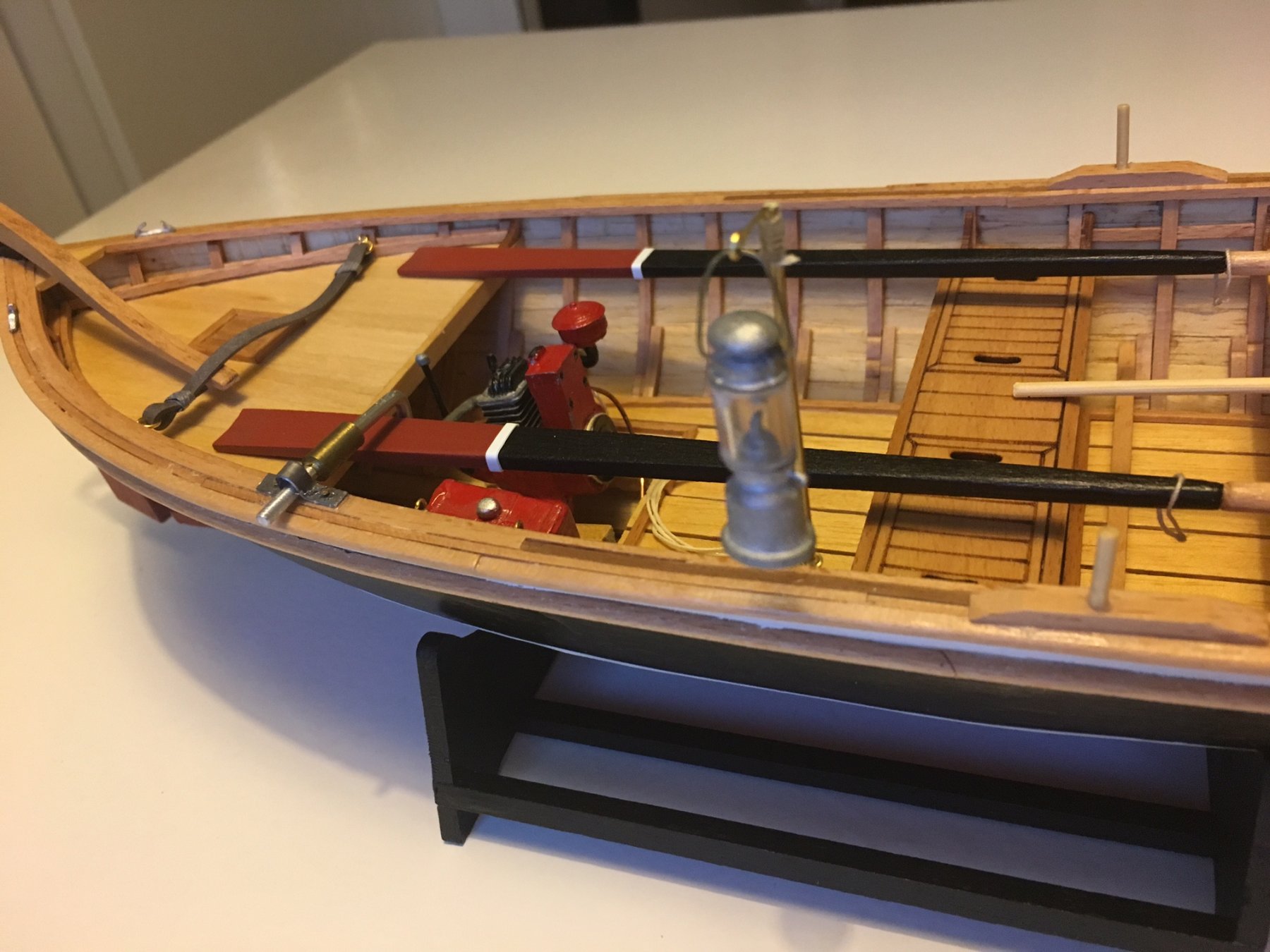
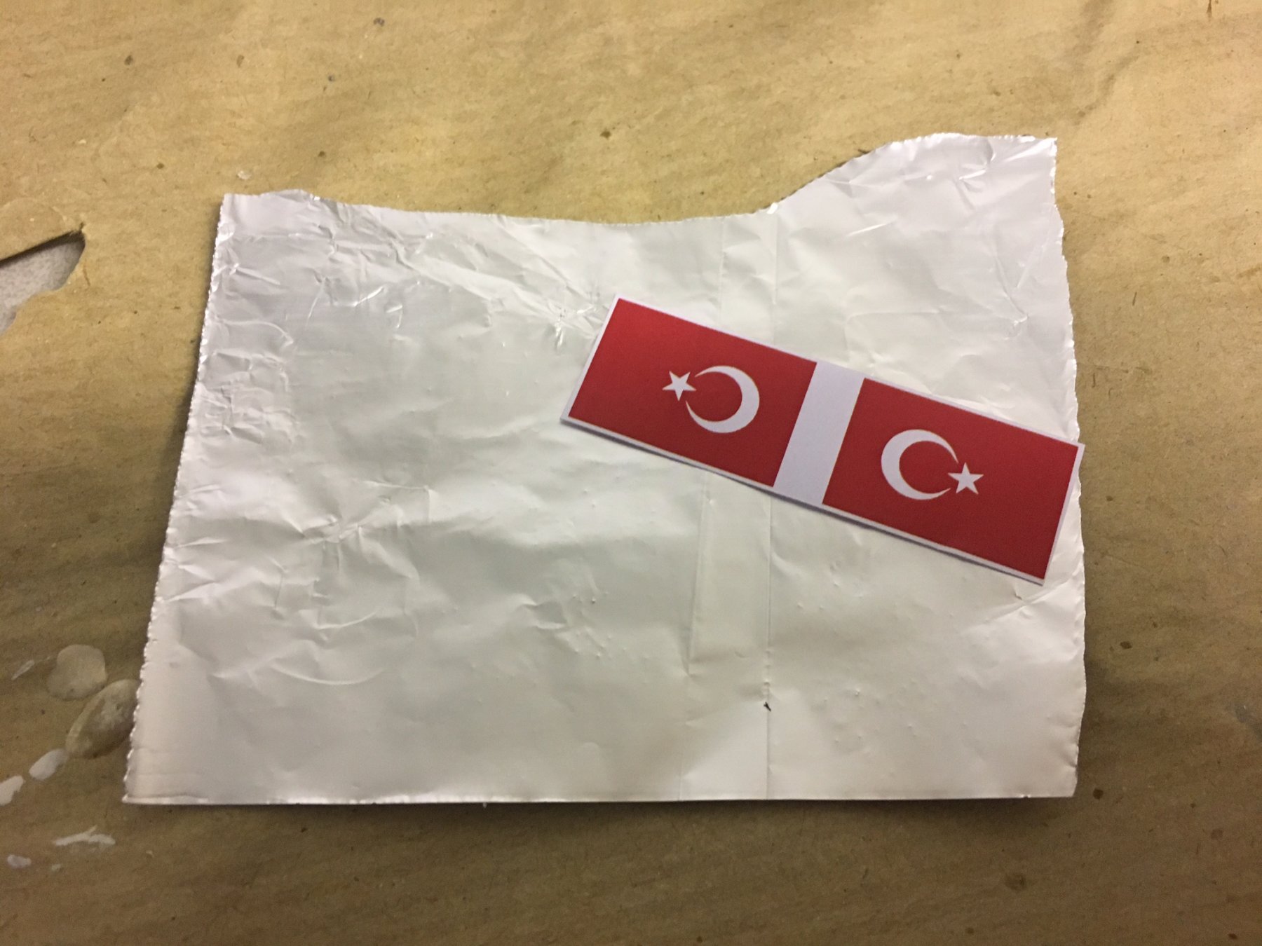
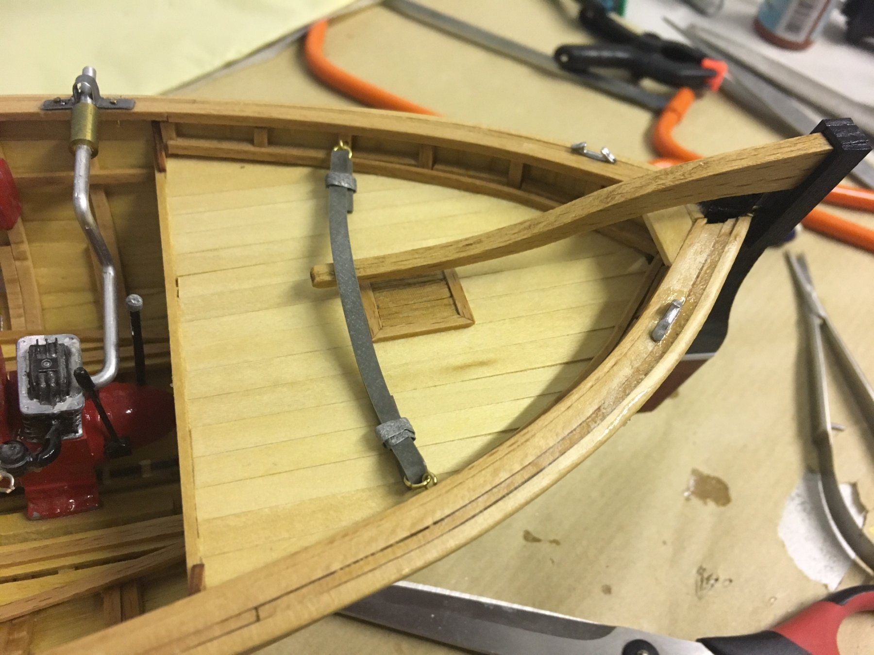
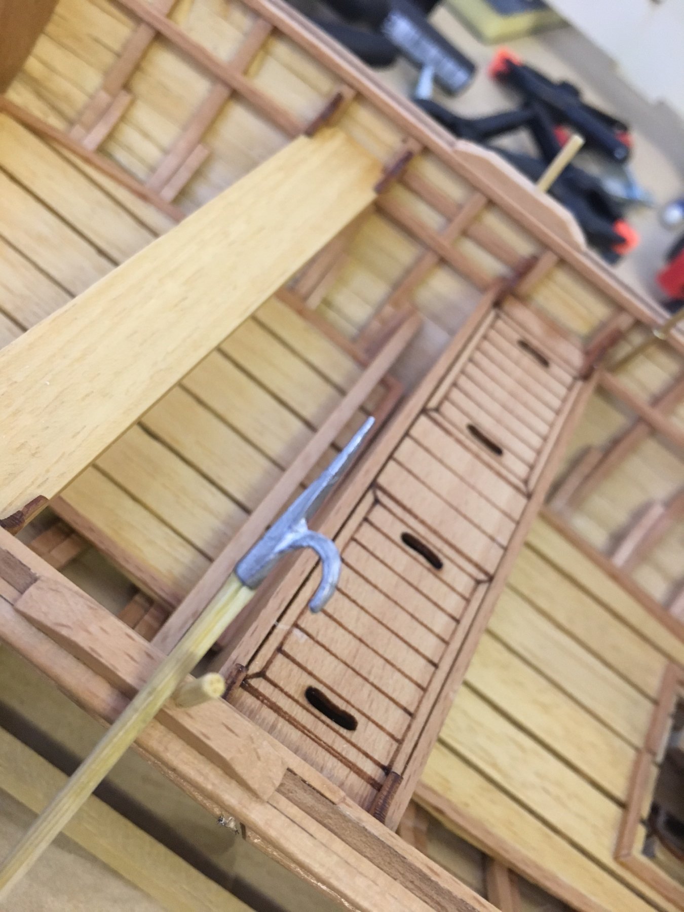
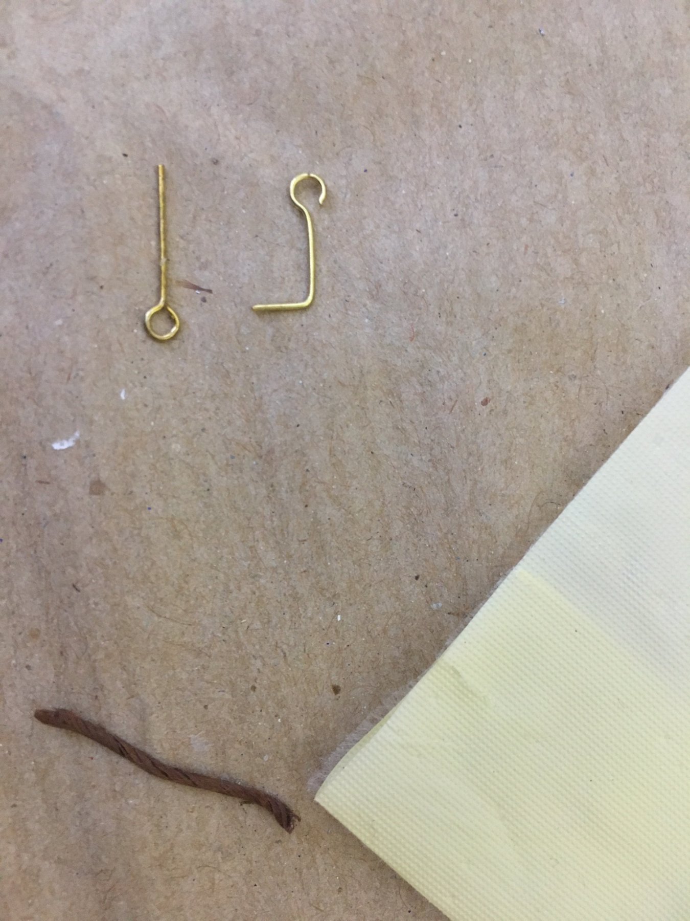
GAS LANTERN
A traditional gas lantern is attached to a rod at a height from the handrails:

- hexnut, mtbediz and John Allen
-
3
-
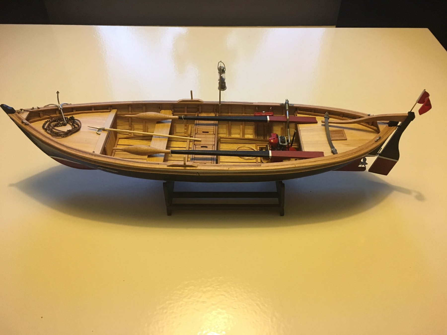
Build days: 20-21
Finished building.
5.5 hours in three days, 49 hours in total.
I am glad to announce that my Bosphorus Fishing Boat is finally complete. Here is a log of final steps:
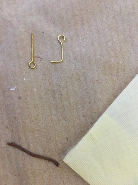
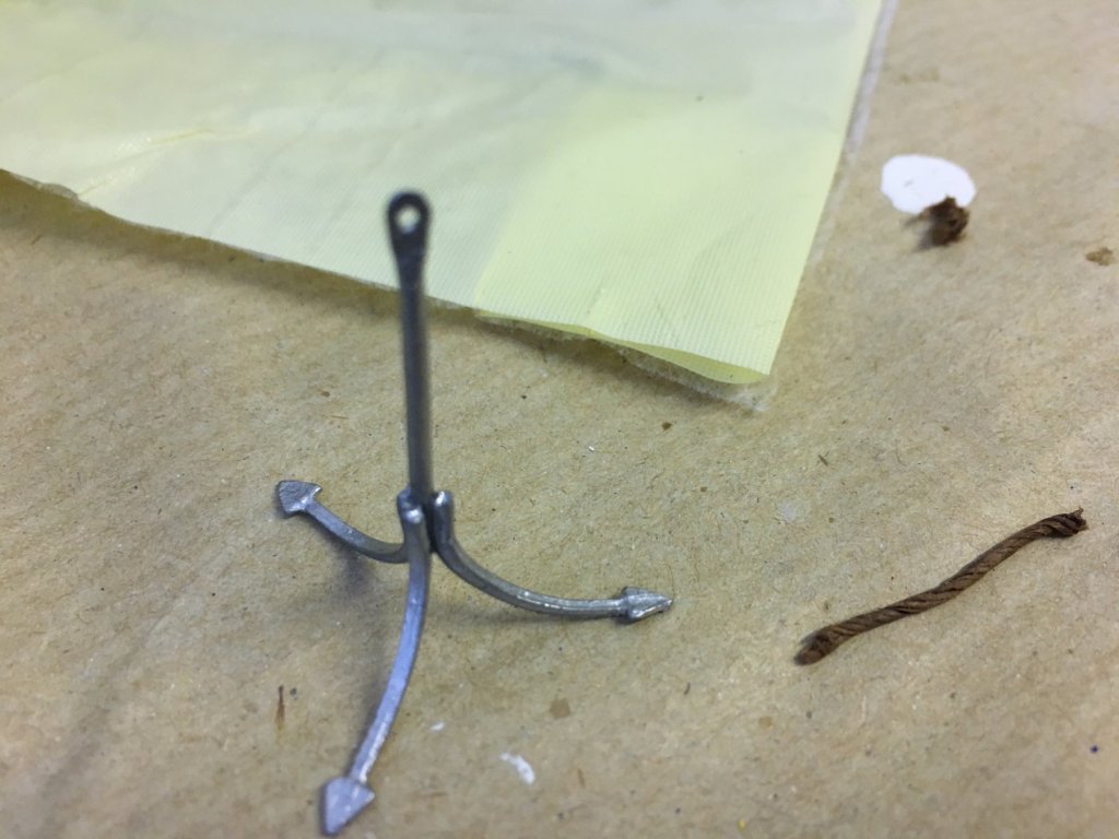
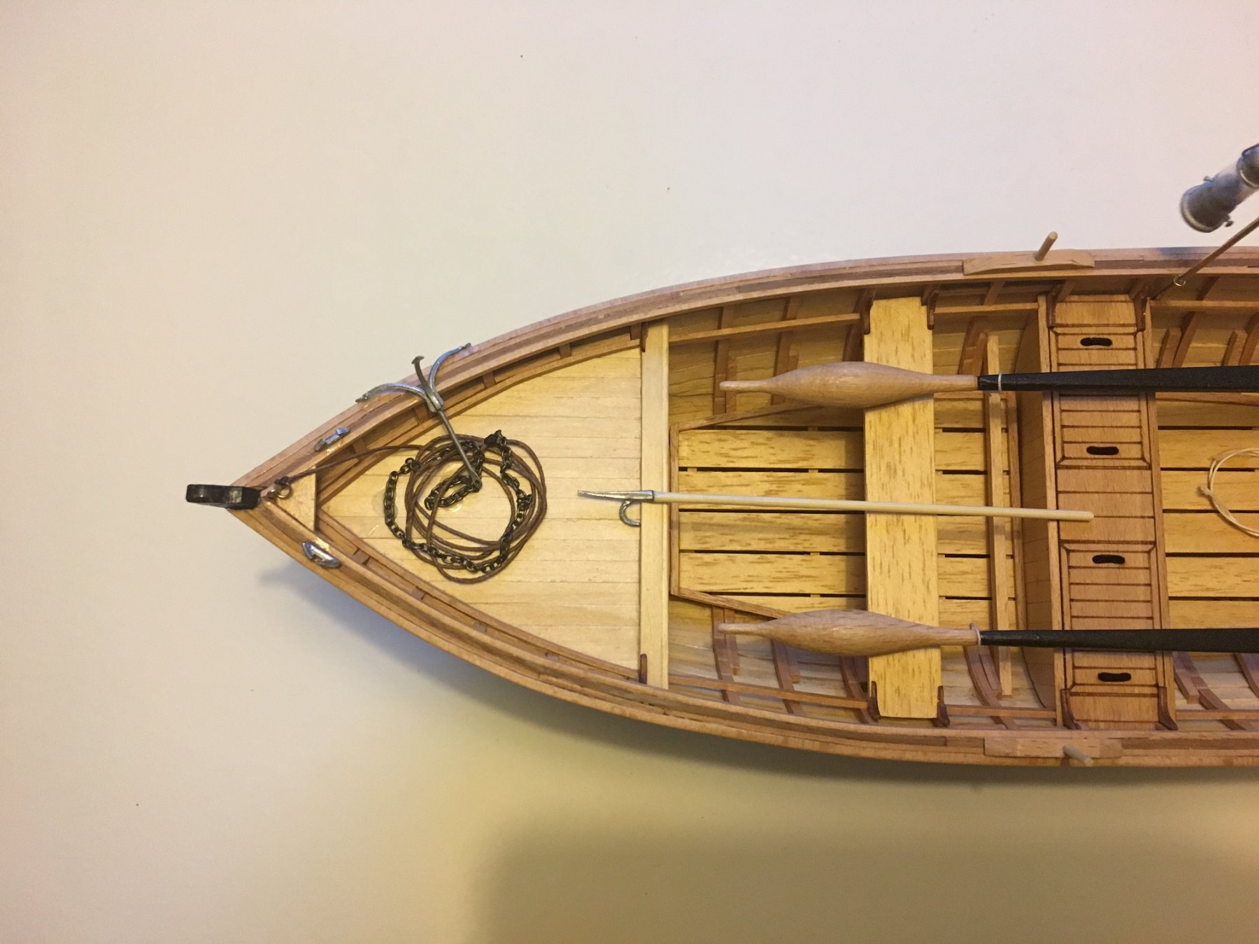
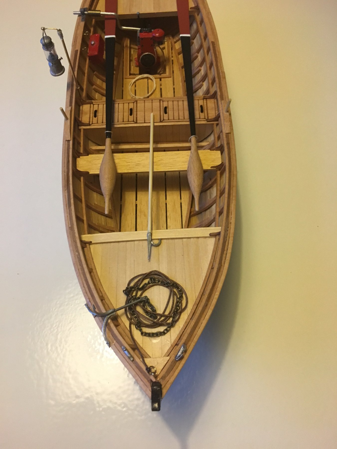
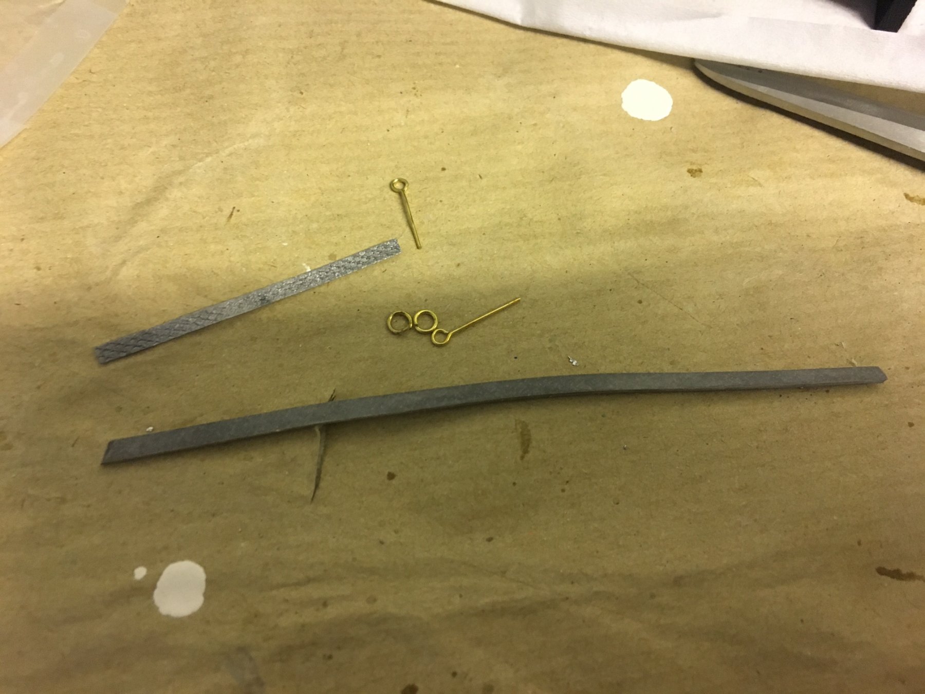
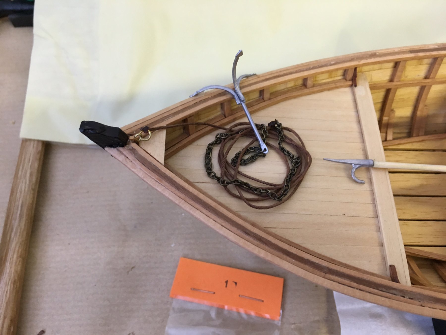
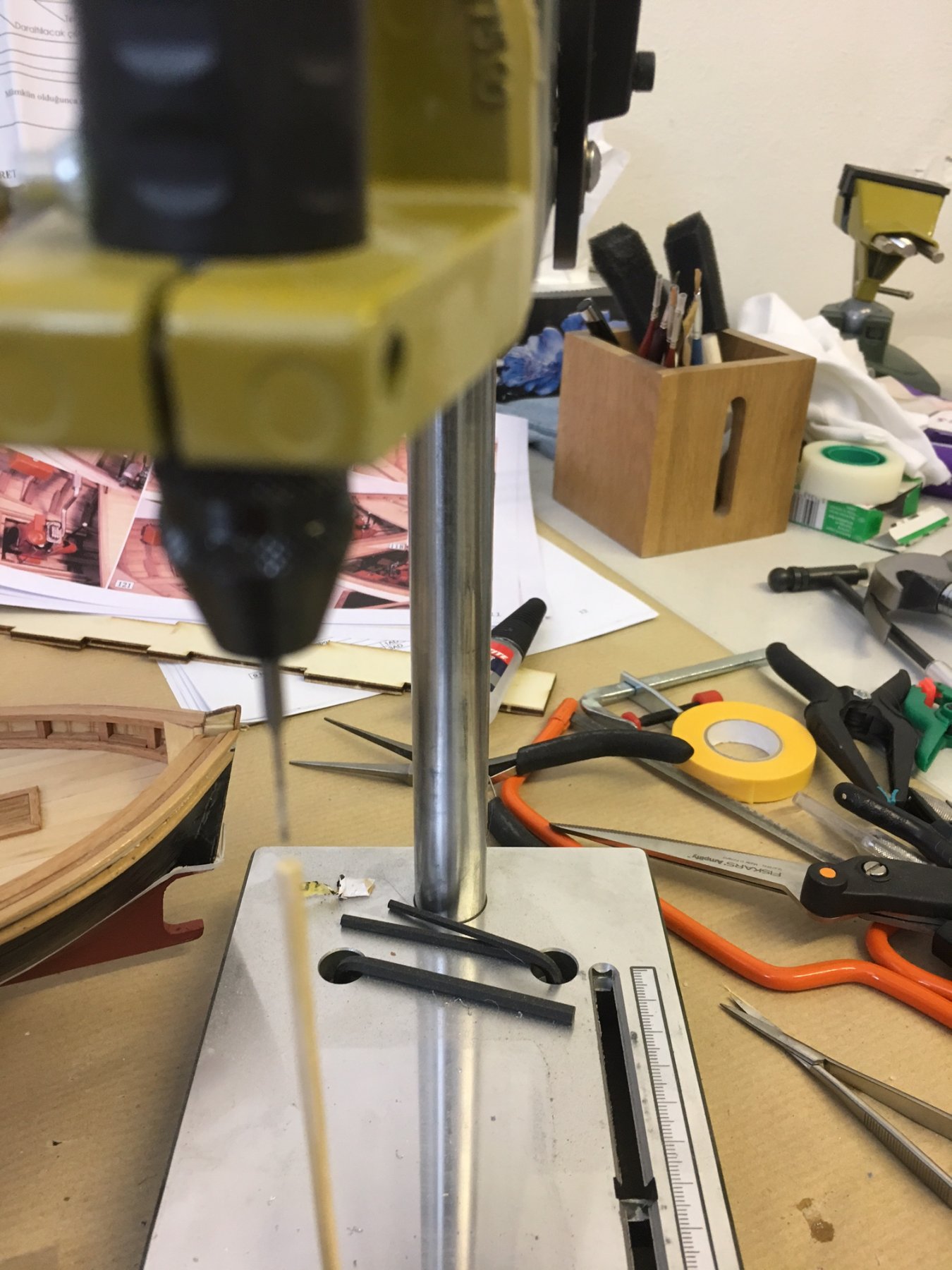
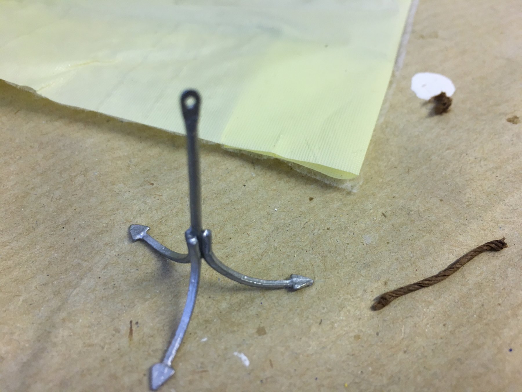
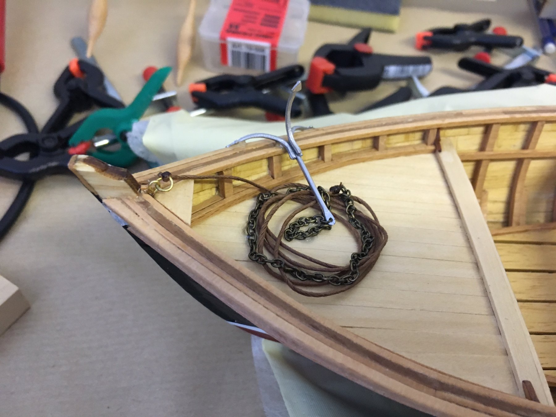
ANCHOR
Anchor consists of 3 hooks to be glued to the main rod, which is attached to a chain and finally to a thread.
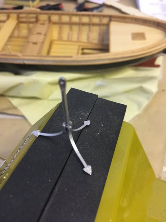
I had to drill the hole which the chain is hooked using a 0,5mm drill bit.
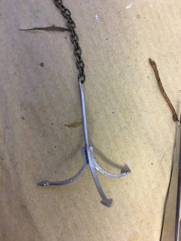
And in place:

-
Build day: 17-18-19
3 hours in three days, 43.5 hours in total.
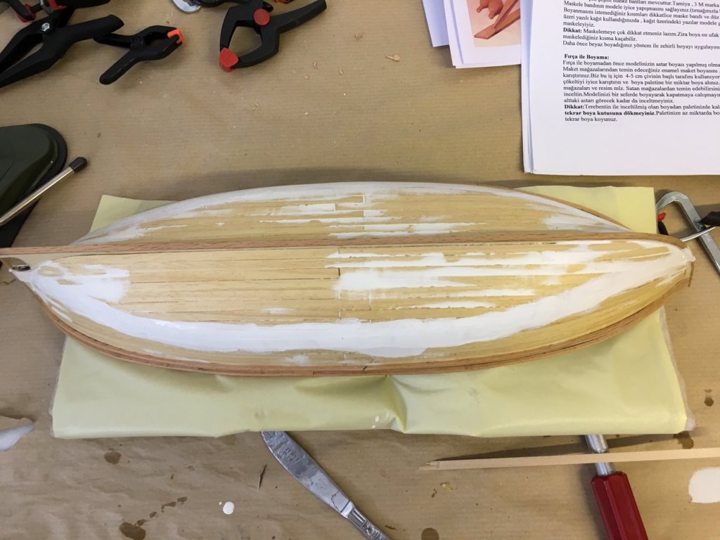
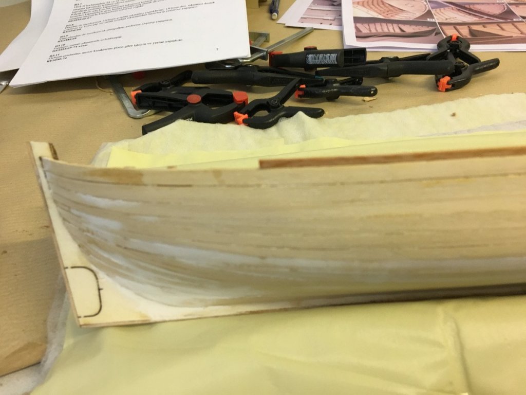
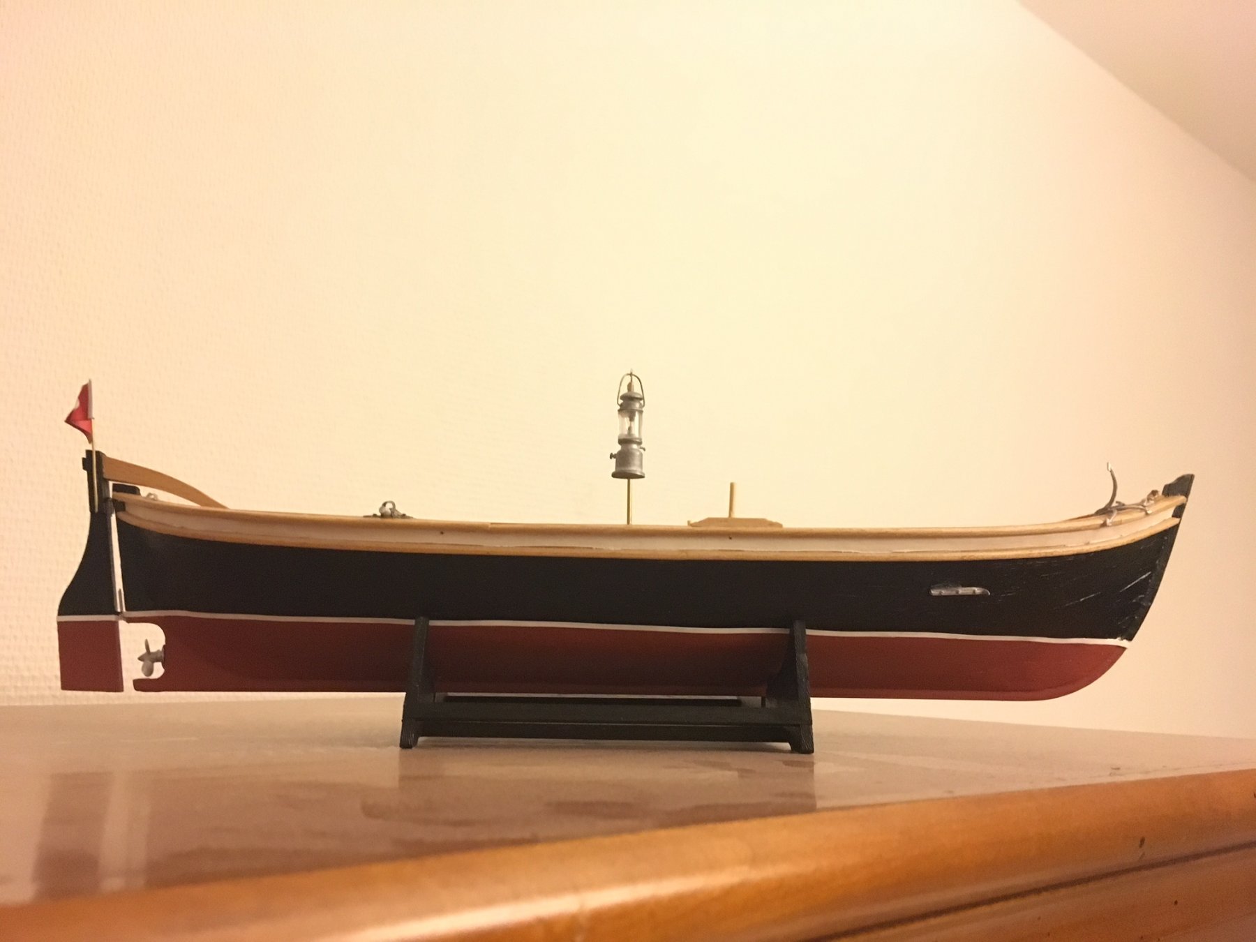
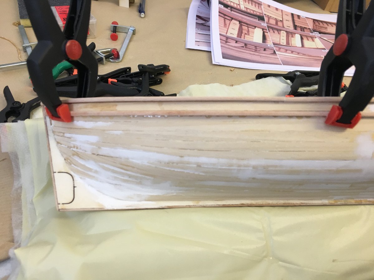
It is about time to start painting the hull, i.e. before installing the ornaments and other accessories. Overall total work did not take too long after all, only waiting in between the drying time of the paint and varnish. Below are some photos.
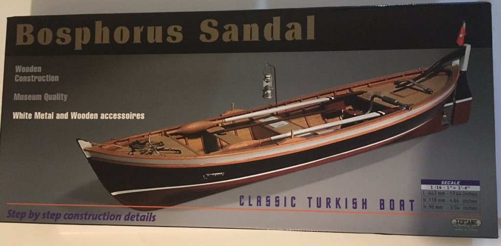
Photo from the package. I like the choice of colors therefore I intend to make similar (remember this is a serial production boat which can come in any color so it is up to you to paint it how you like it or where you want to display it):
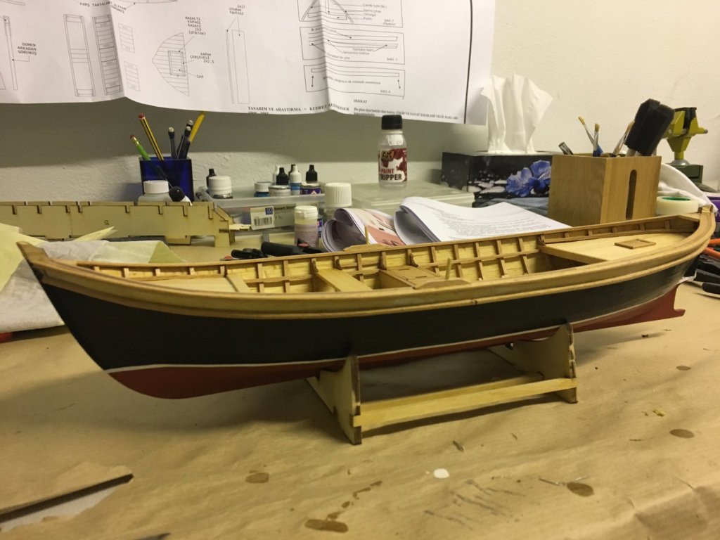
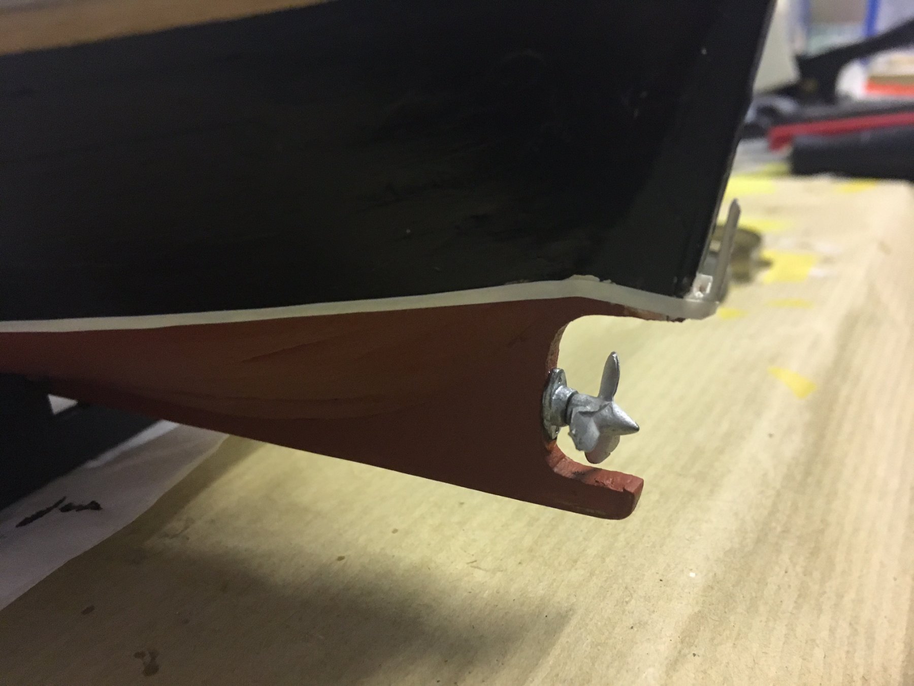
White stripe at waterline:
Varnish inside

This is the status at the moment. Rudder and oars will be painted separately. Thanks for watching.
-
Thanks Eddie! I am almost gettin' there!
Cheers,
Aydin
-
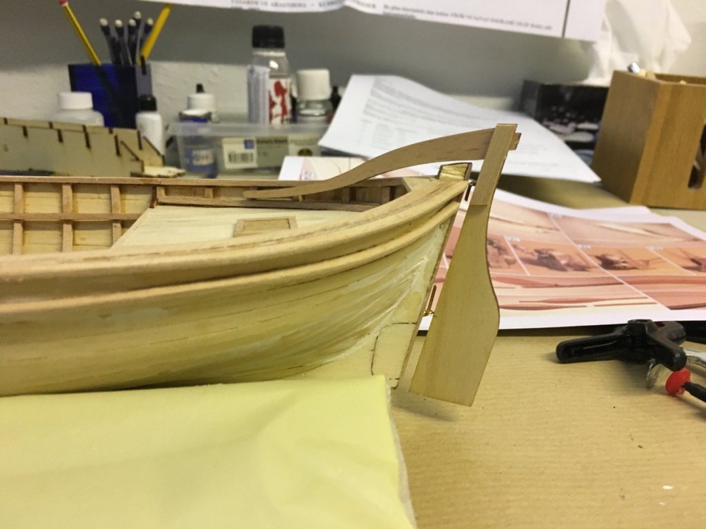
Build day: 15-16
6 hours in two days, 41,5 hours in total.
In these two days I worked on
- the handrails,
- engine ramp,
- rudder,
- oars
- engine
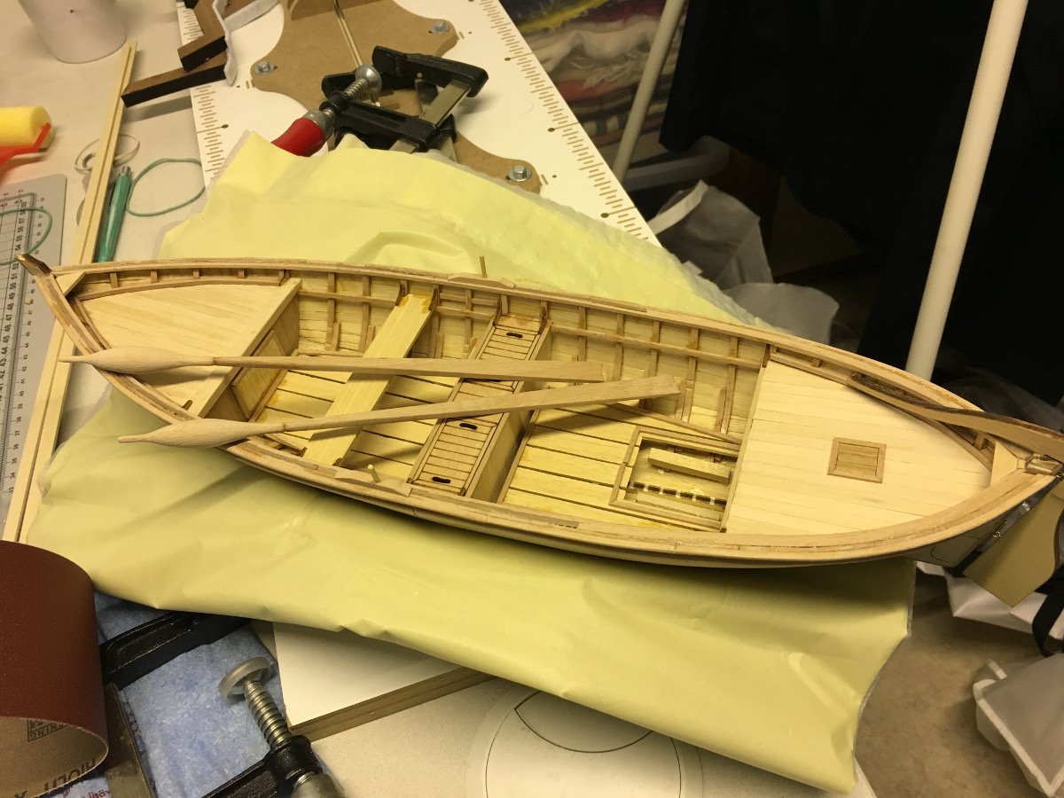
After these steps now the boat is ready for painting. Once the essential parts have been painted/varnished, it will be about installing the other accessories like hooks, anchor, spear etc.
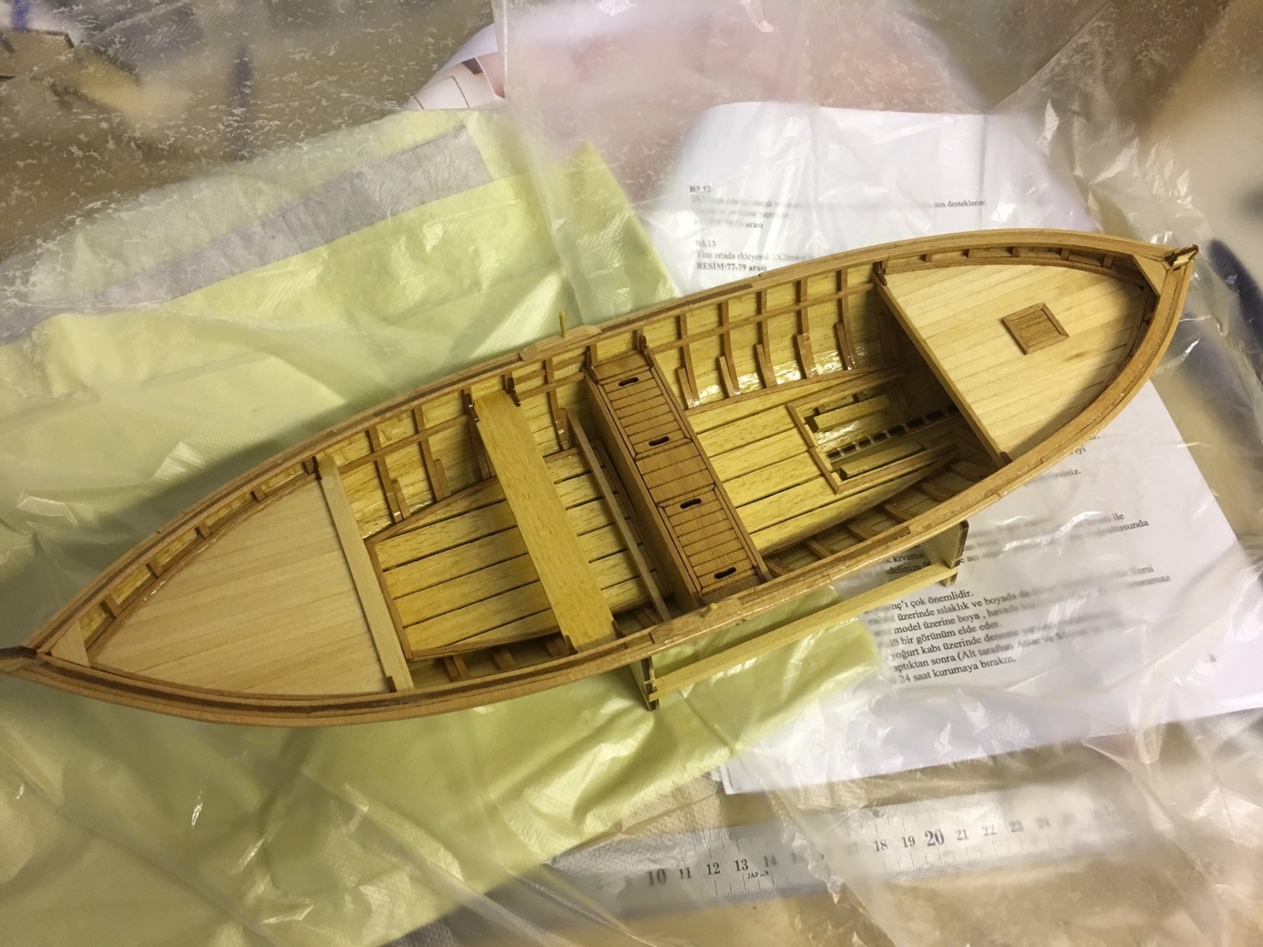
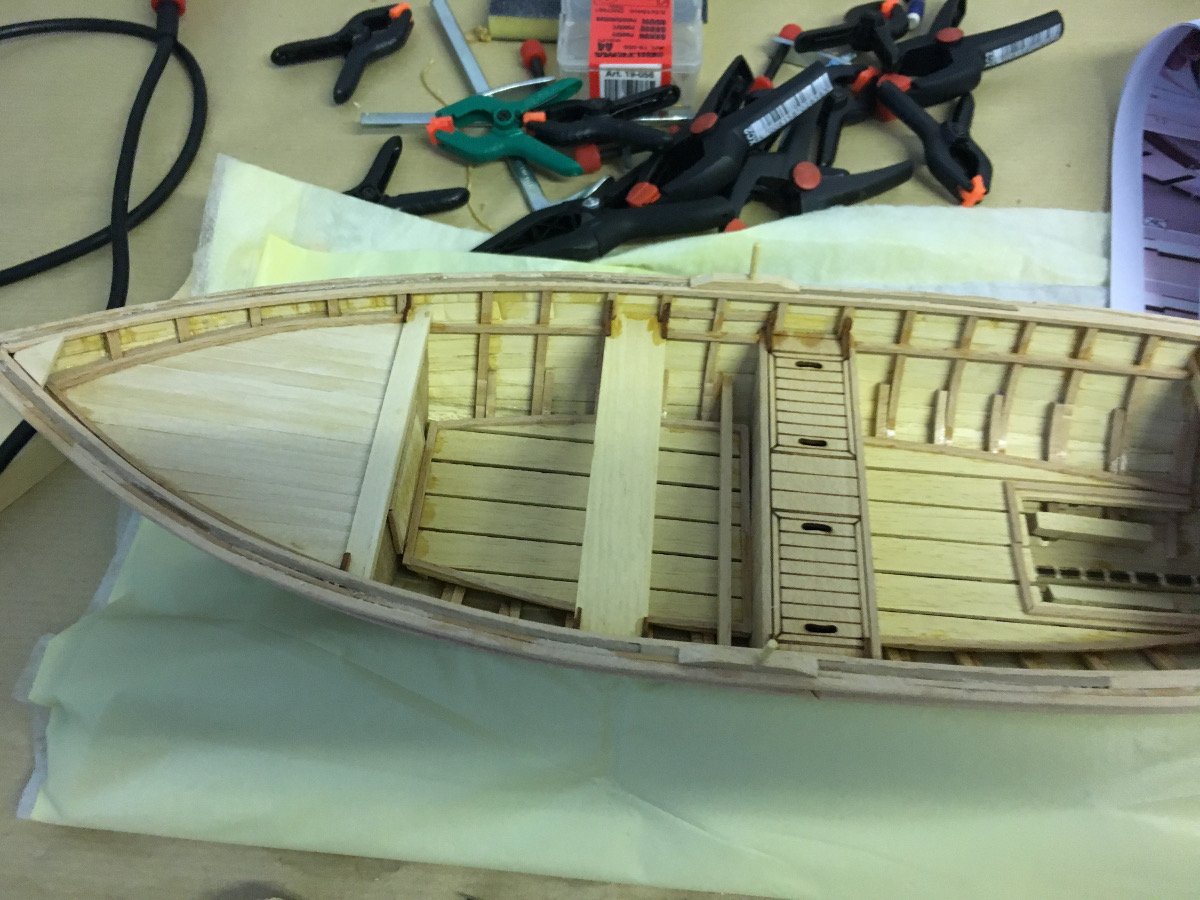
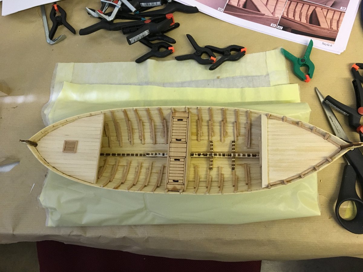
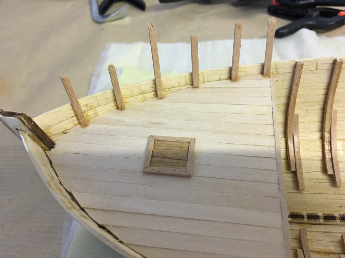
I am posting quite many photos below, with some explanations where I feel helps understand what's going on.
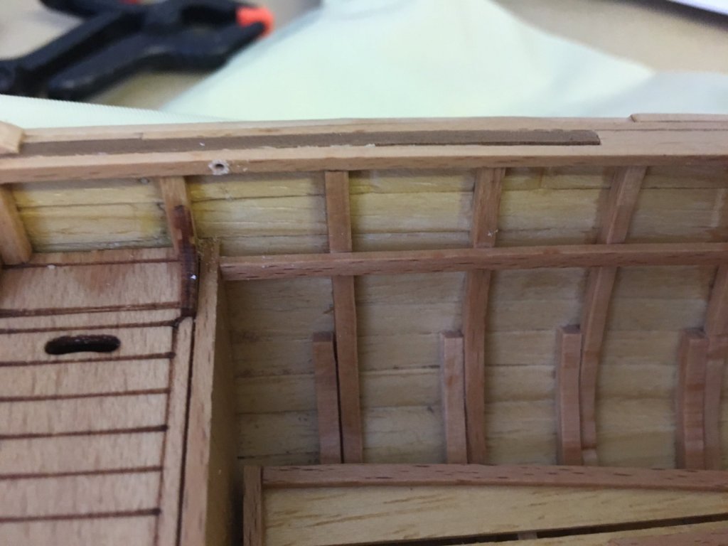
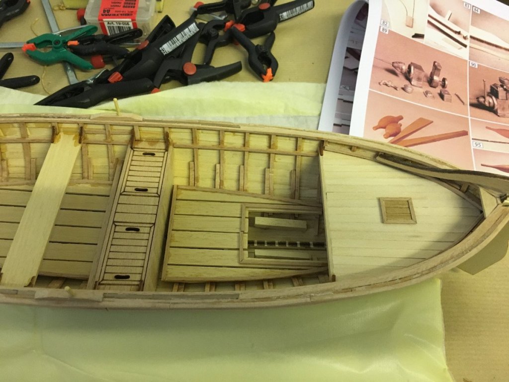
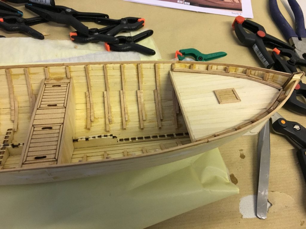
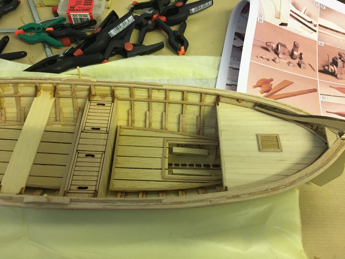
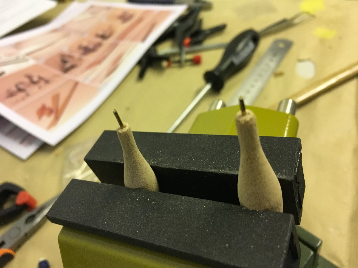
Below I installed the posts for the oars (you'll notice them in both port and starboard, a bit offset the seat):

Engine ramps:
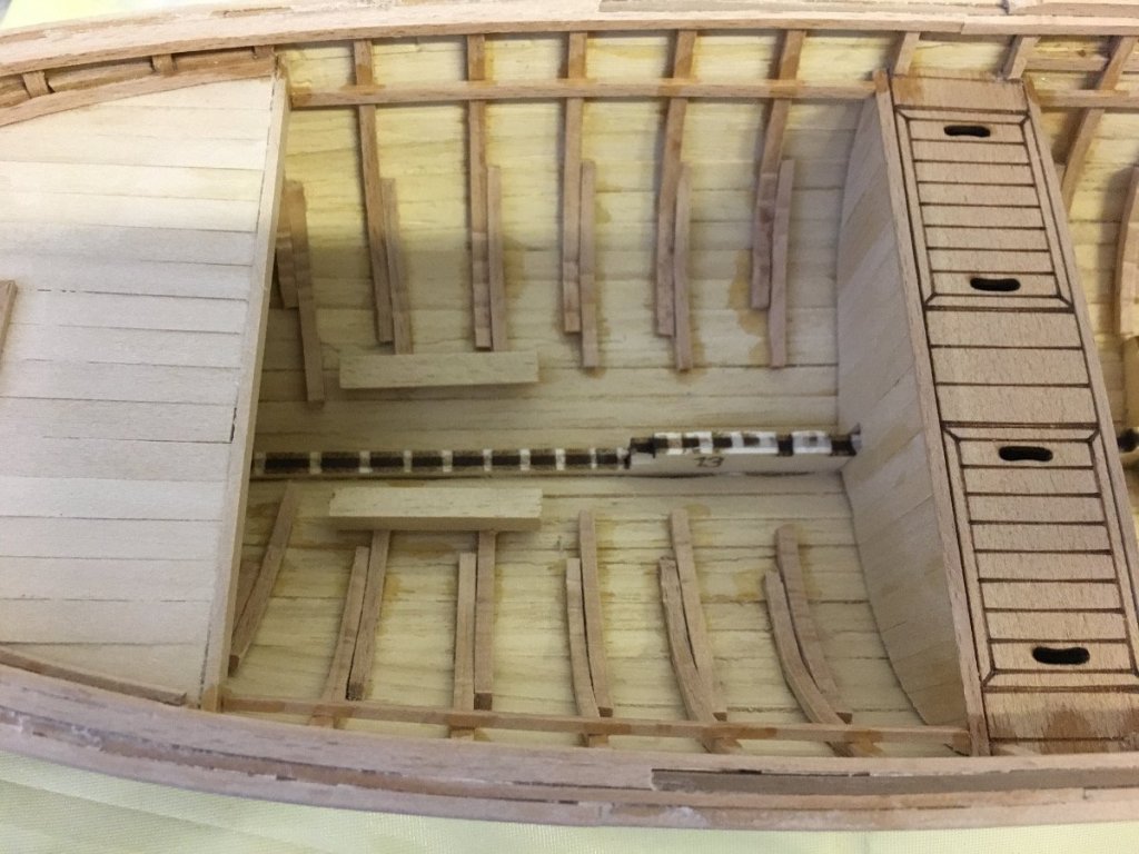
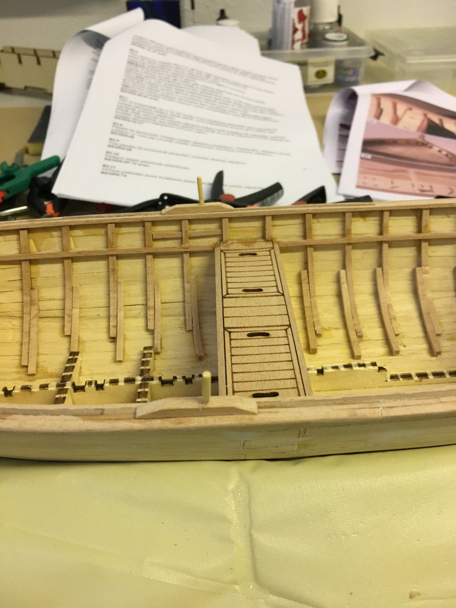
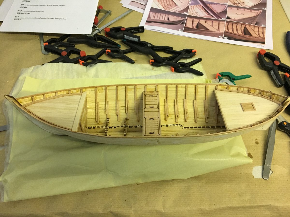
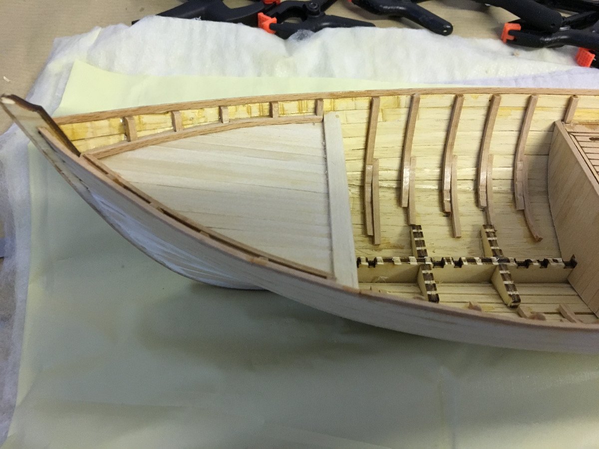
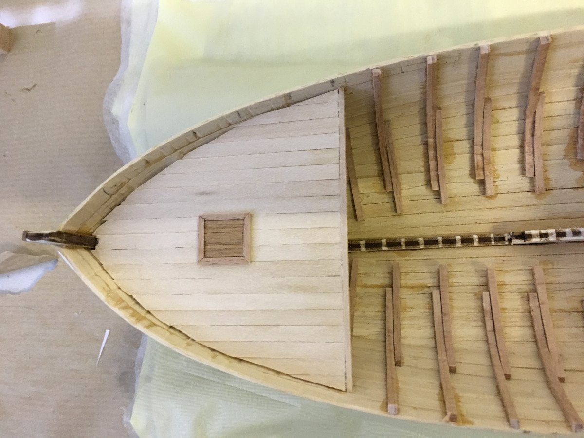
Floor boards getting frames:

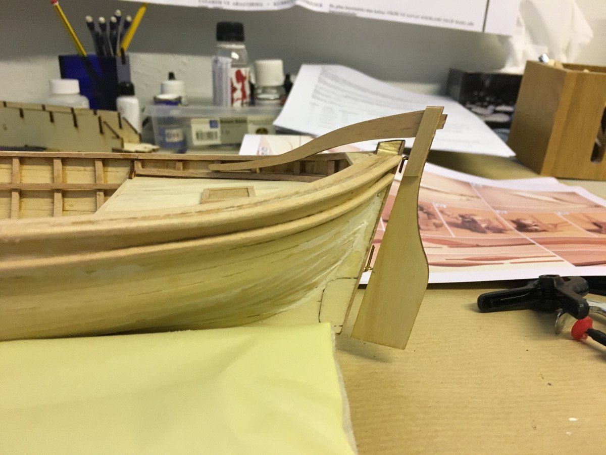
D shaped strips following the handrail on the hull:

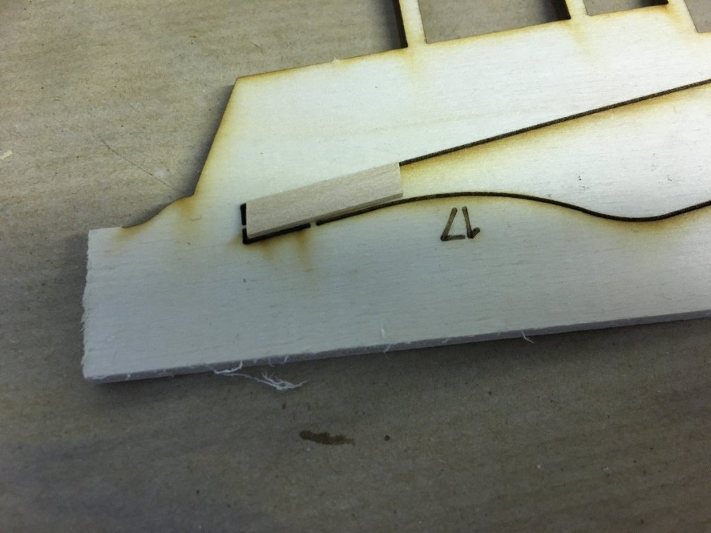
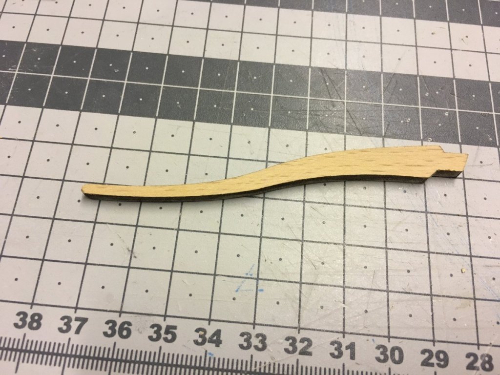
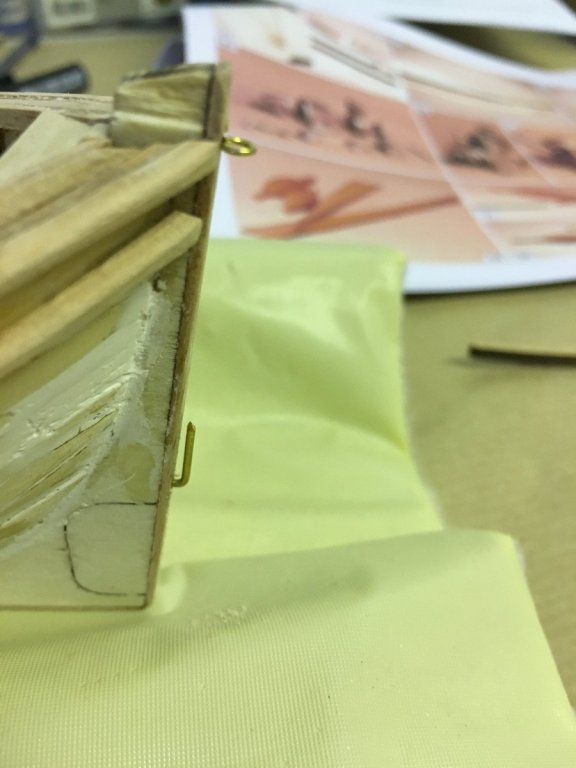
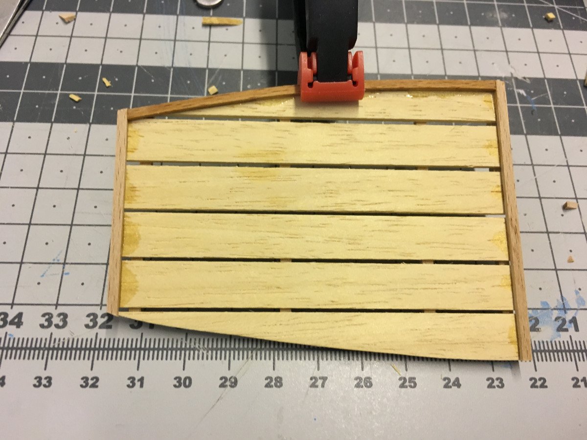
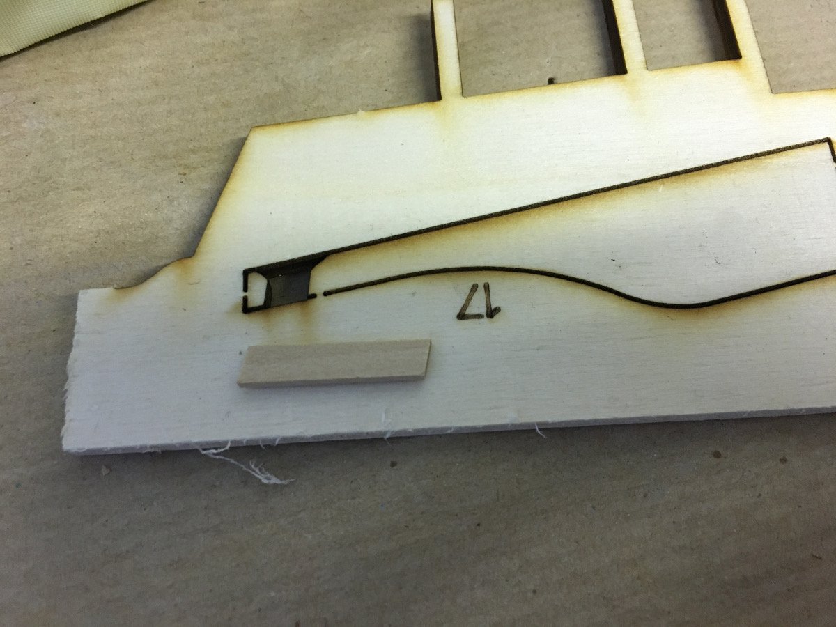
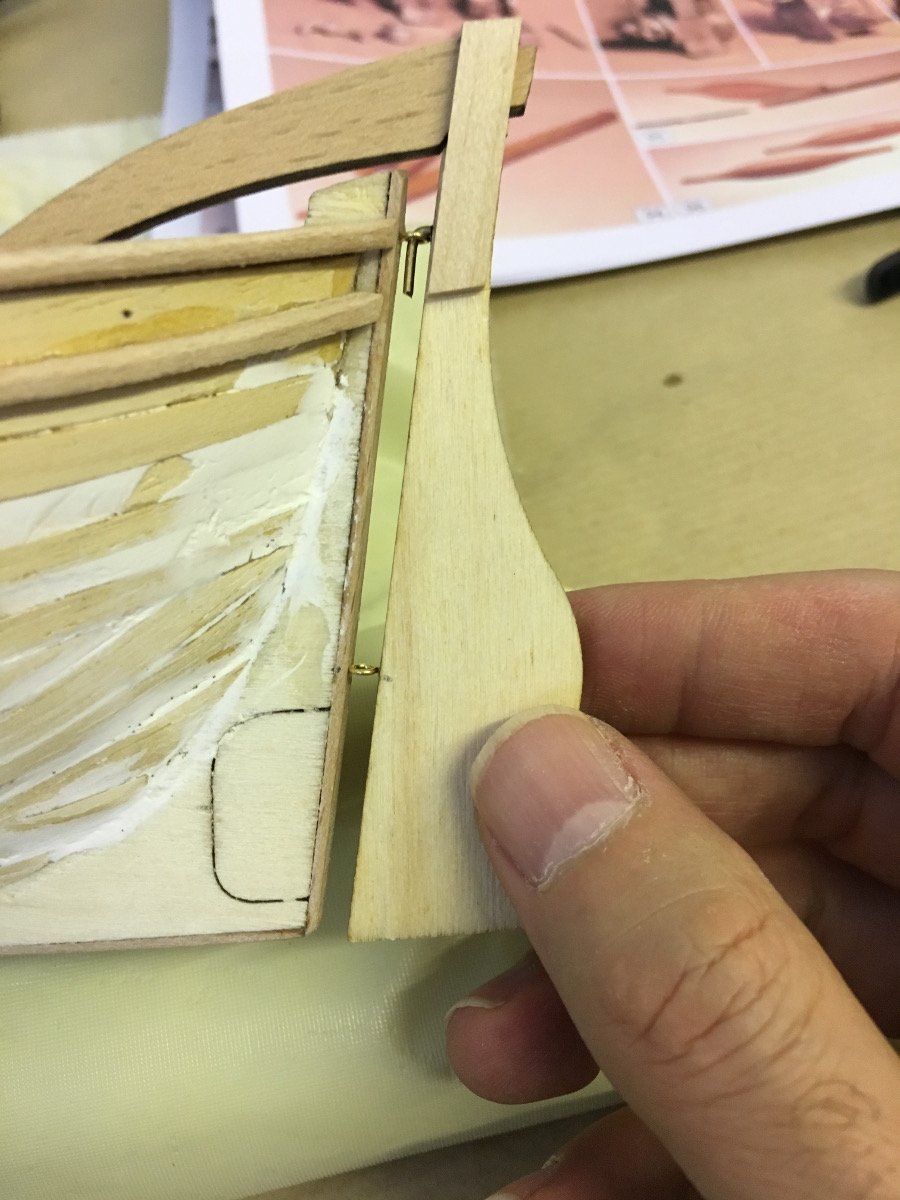
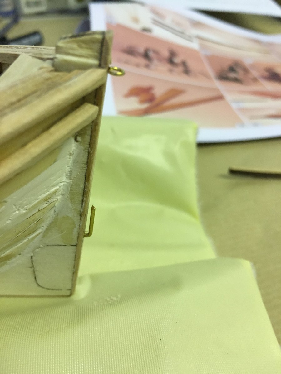
THE RUDDER
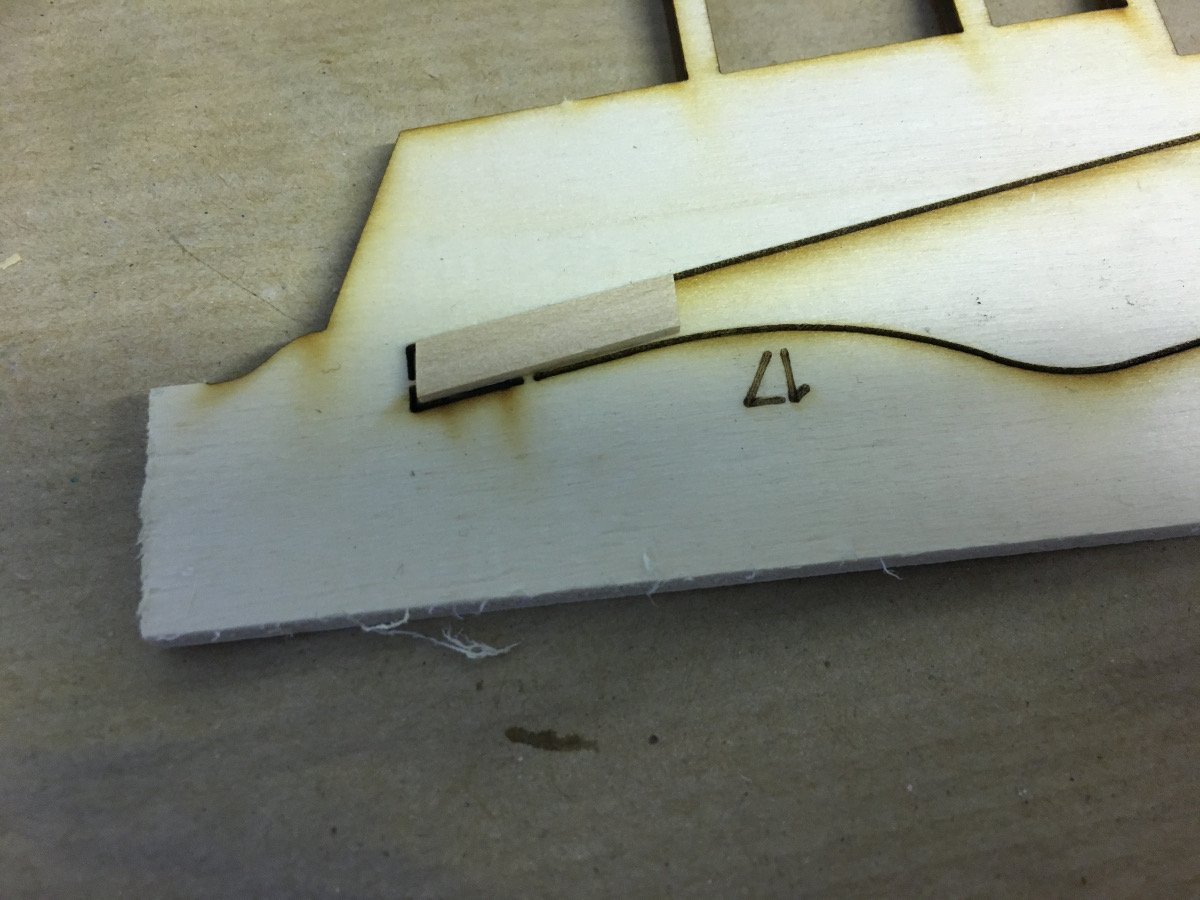
Construction of rudder follows and interesting and smart way: In order to maintain correct size of the slot where the handle will be inserted, one of the support strips is glued before removing the rudder pieces from the plywood.
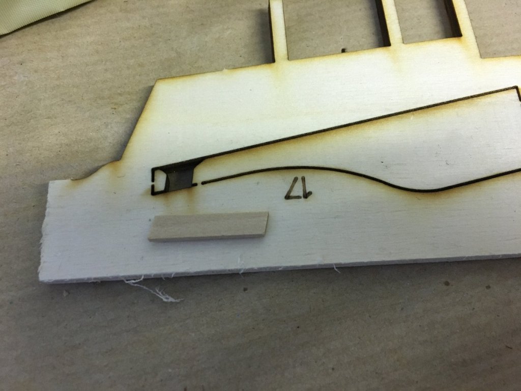
One of the support pieces glued:
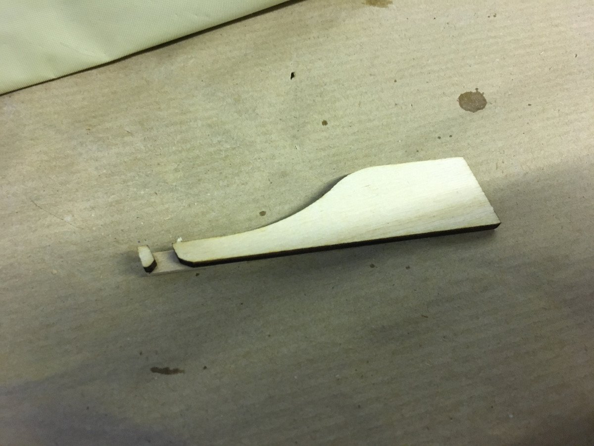
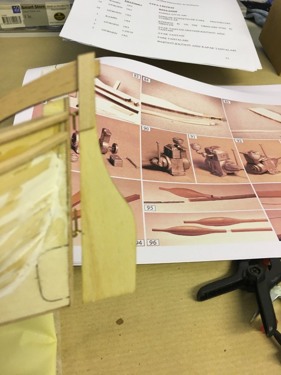
The parts have now been removed from the plywood:

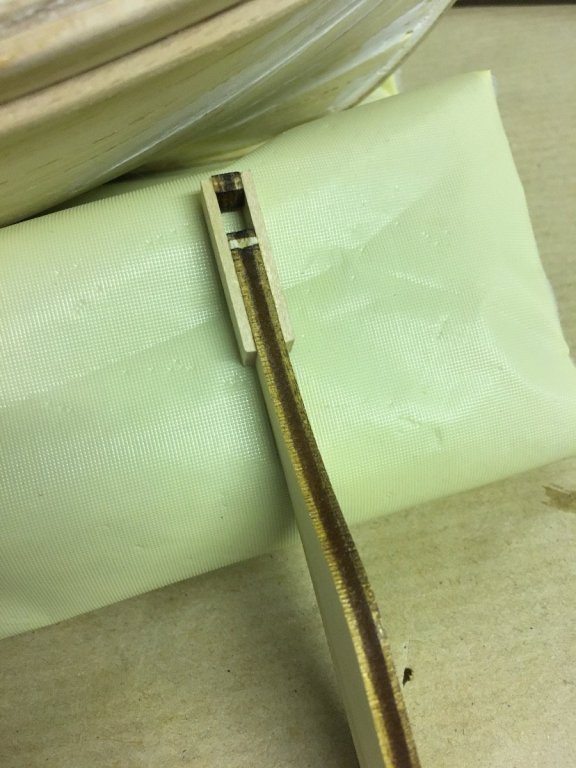
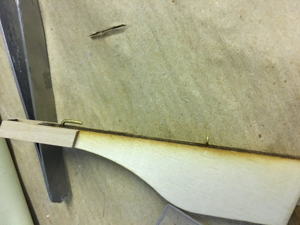
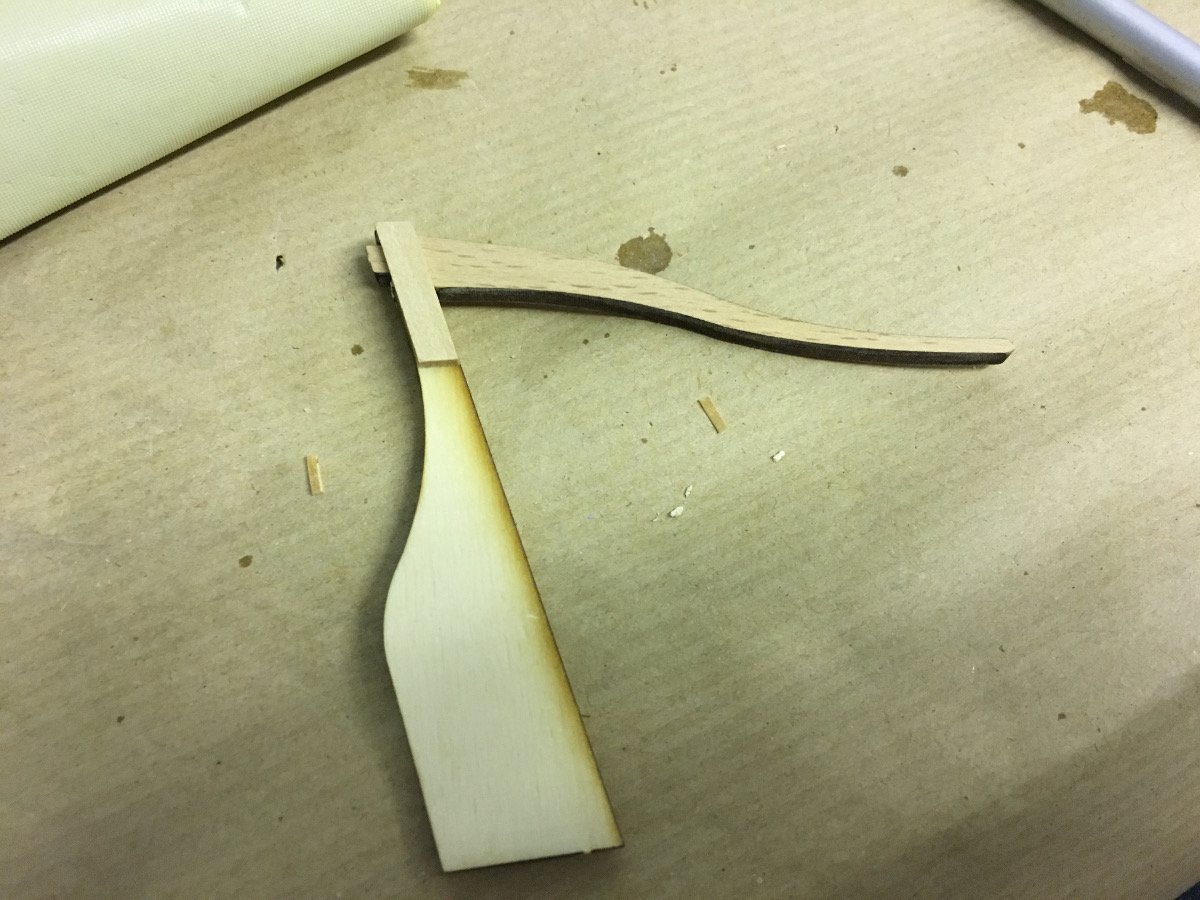
Rudder "handle" is inserted (dry fitted at the moment since it will be on the way while drilling as well as painting):

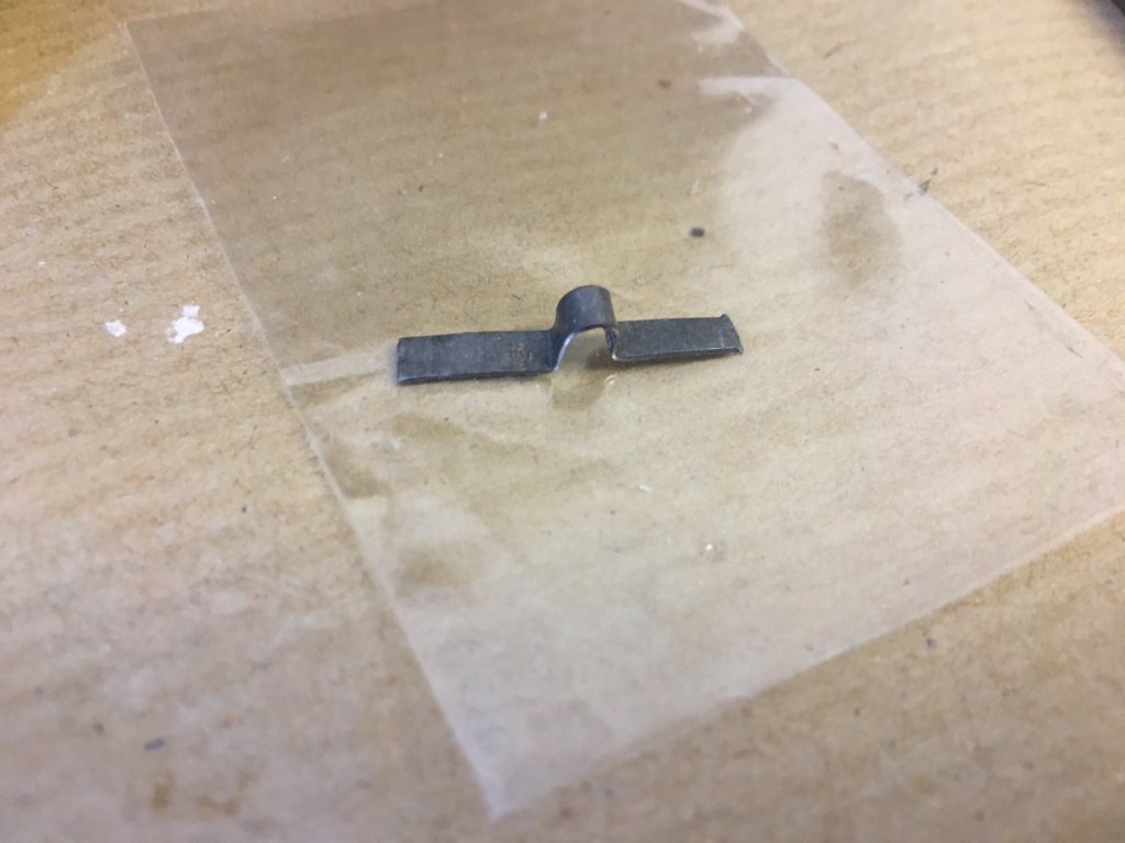
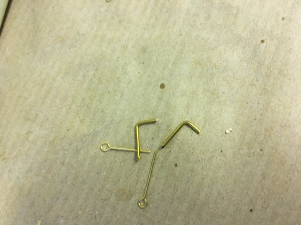
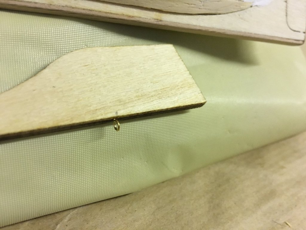
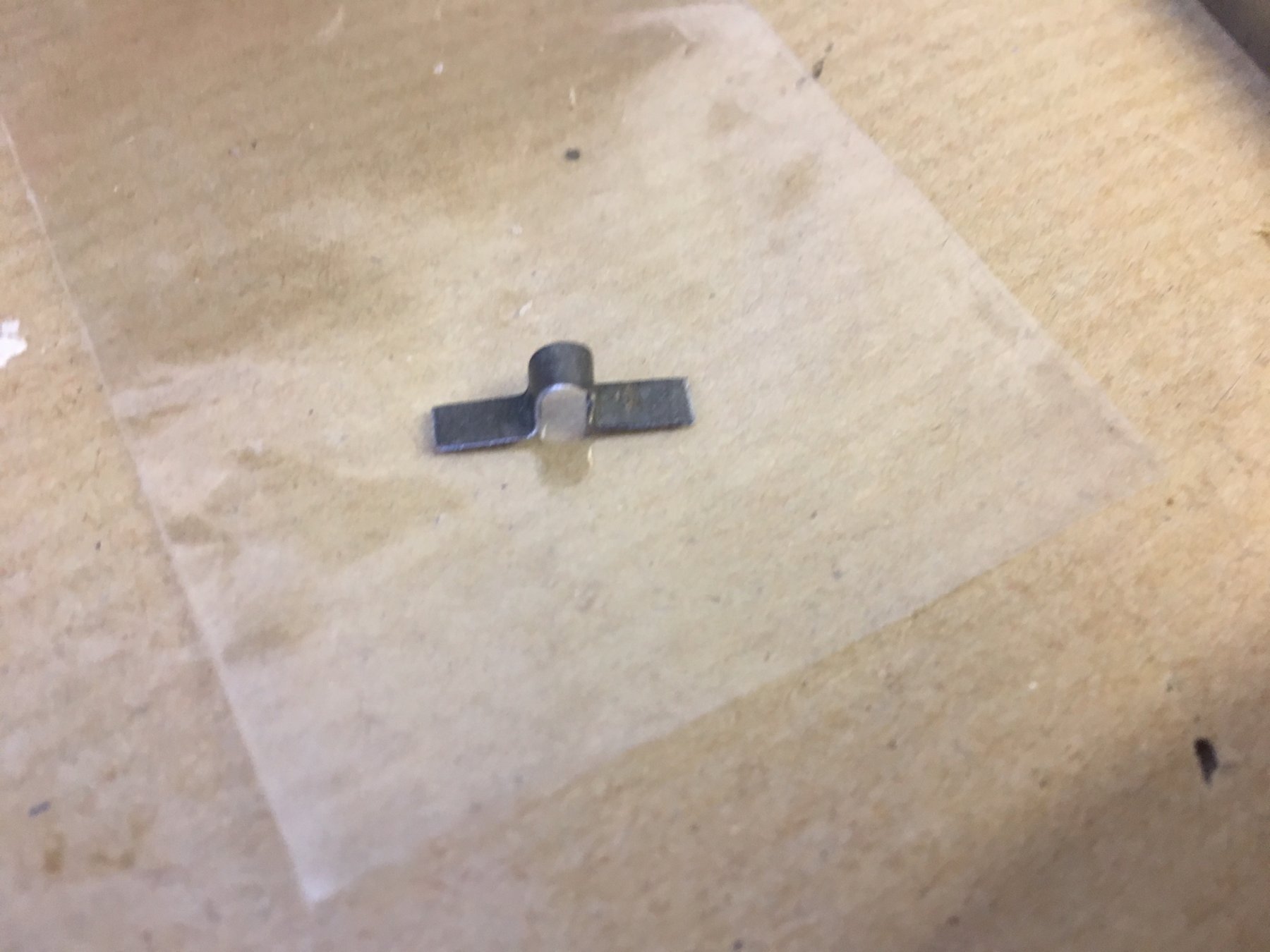
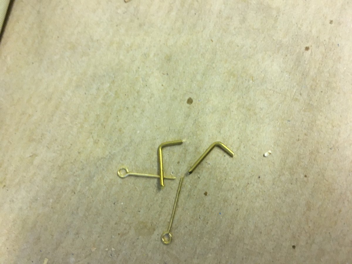
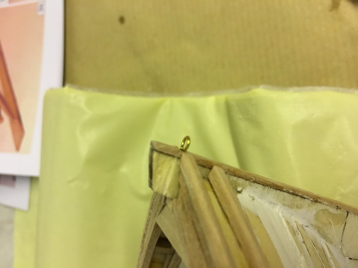
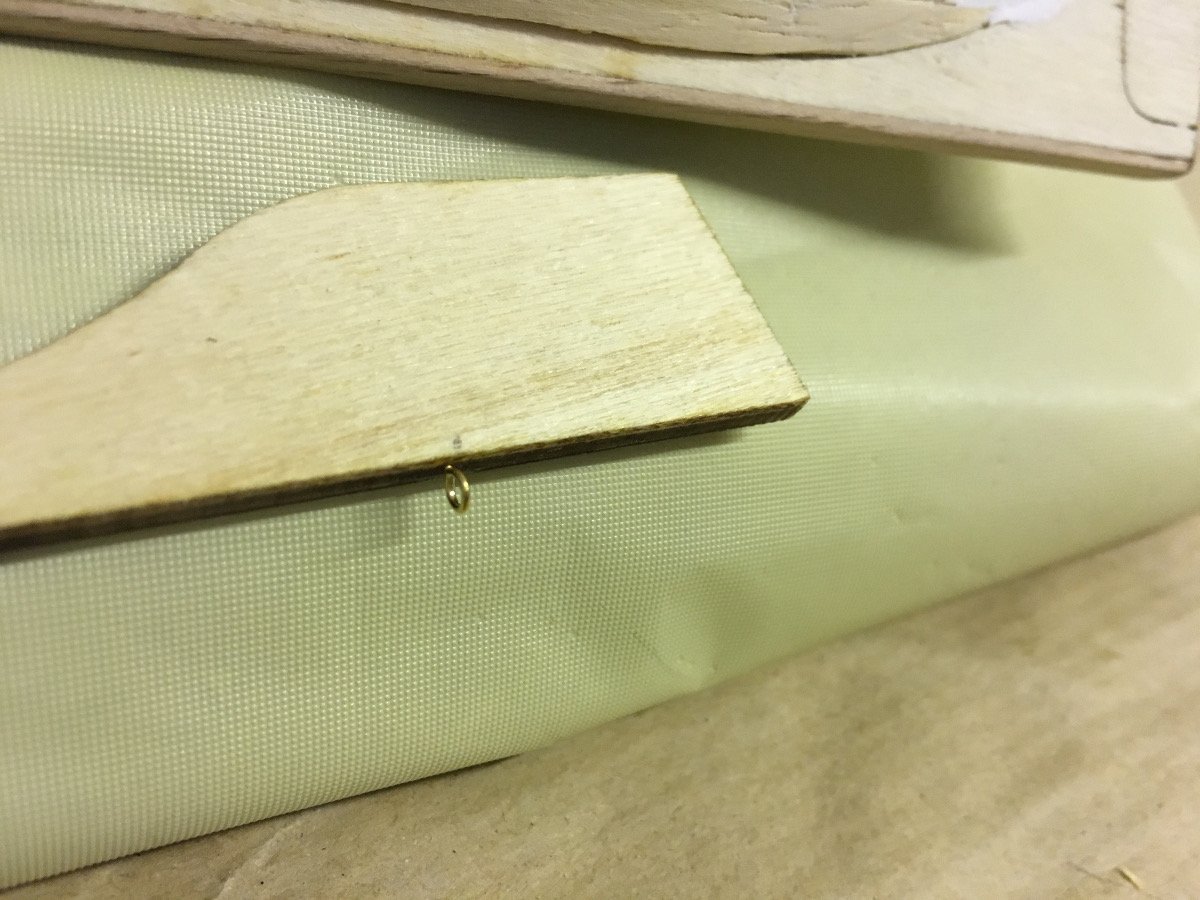
These small parts are used for attaching the rudder to the hull:


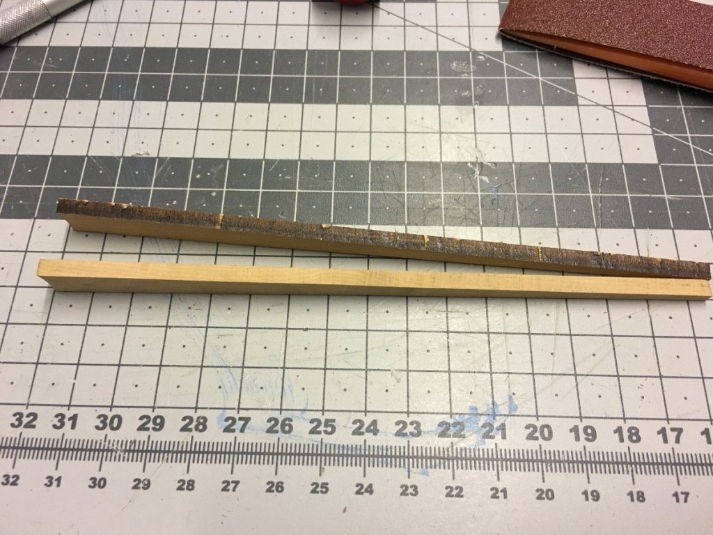
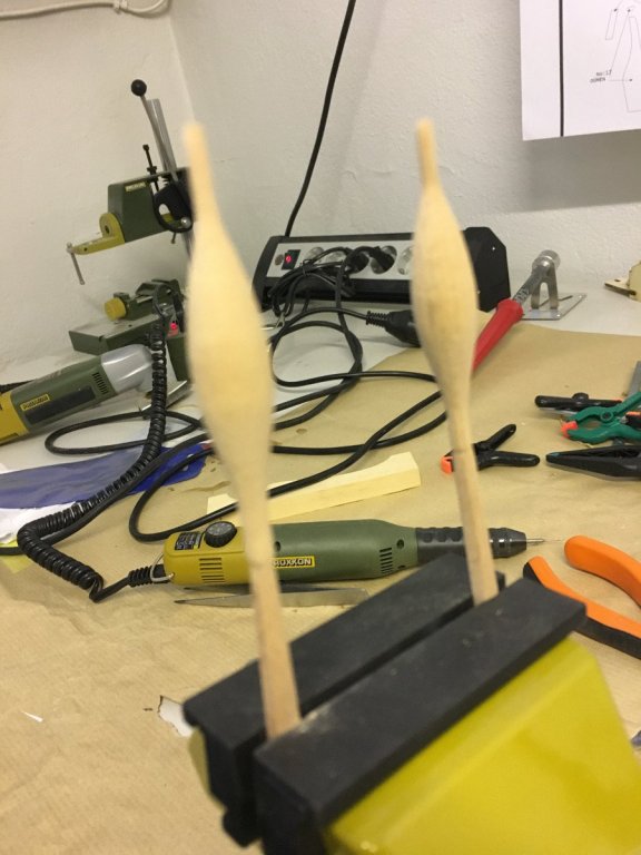
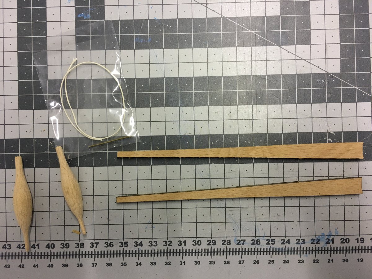
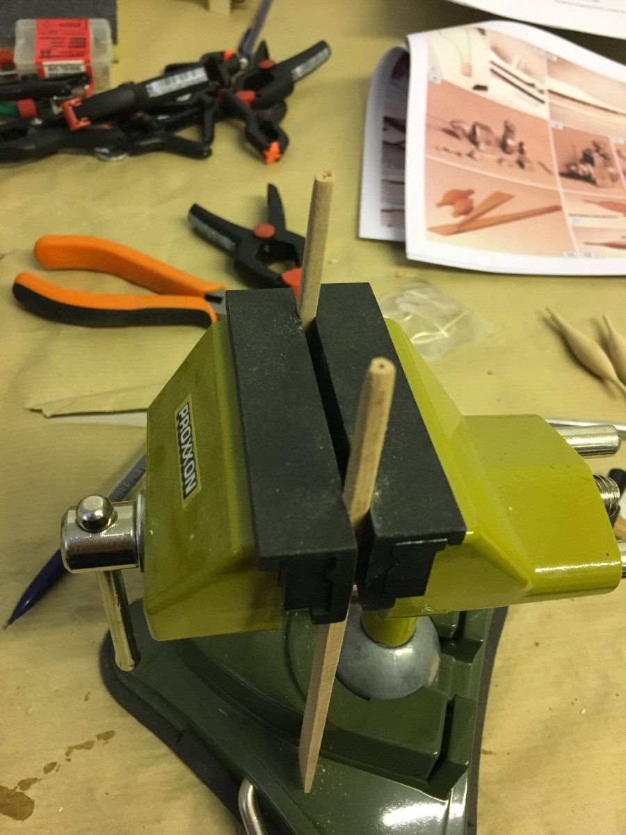
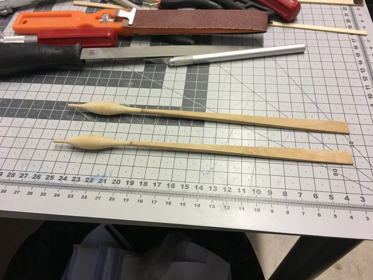
OARS:
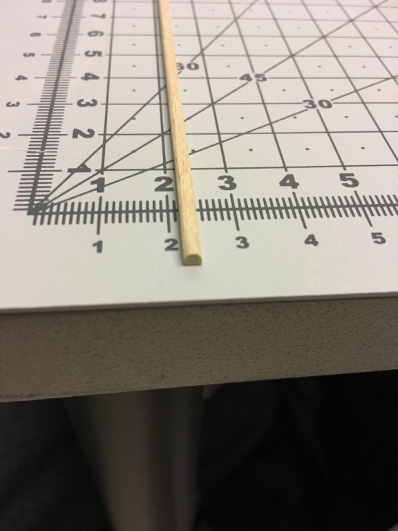
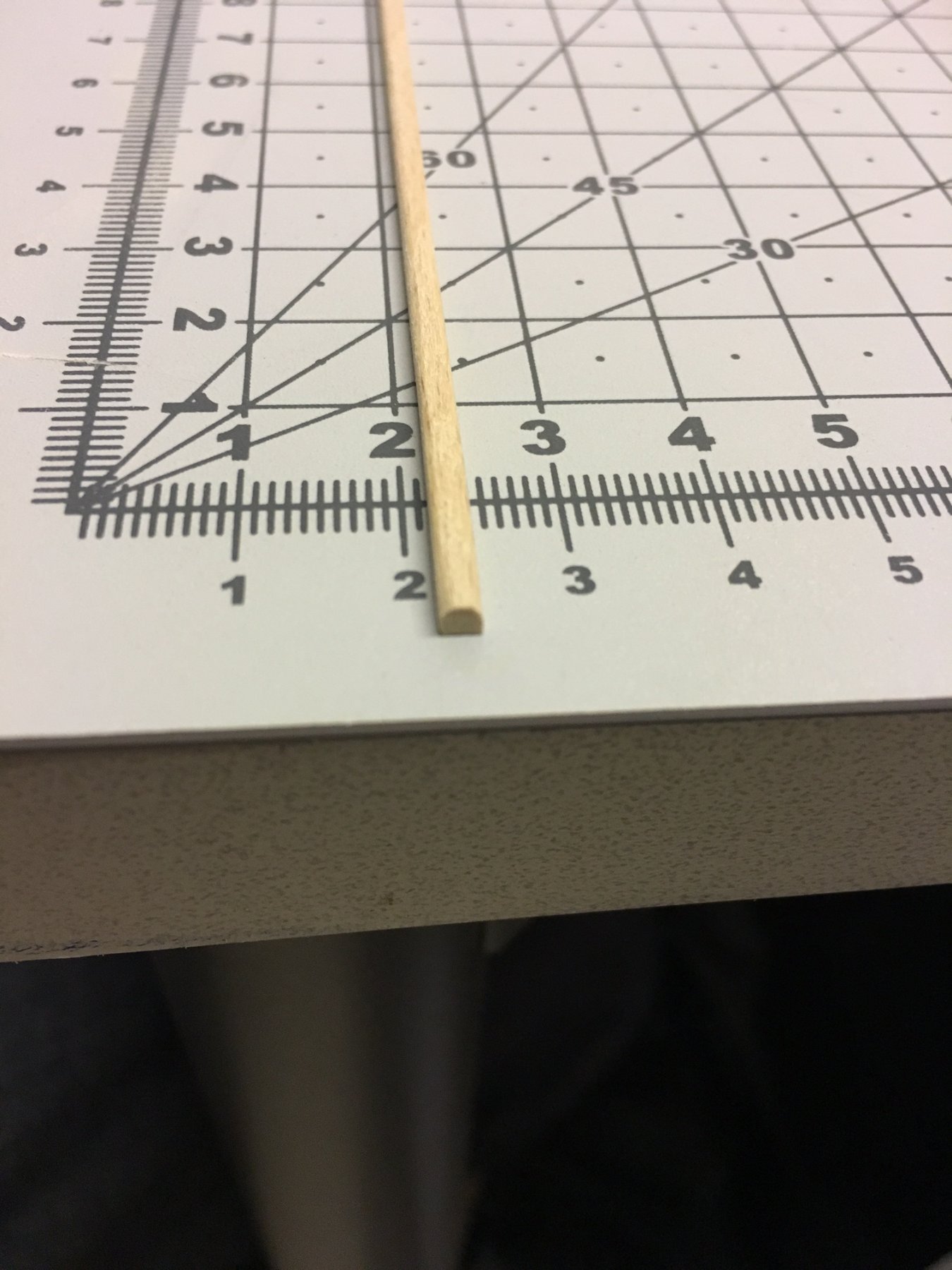
Each one of the oars are made of two pieces. The longer piece which is removed from plywood needs to be tapered on the water end and and rounded on the other end, to fit the second piece. Below is a series of pics to show the progress:
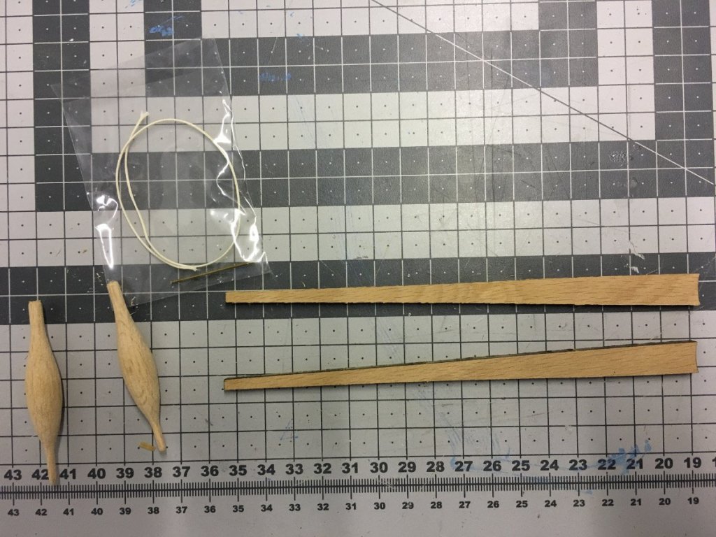
Sanding away the laser cut burns from the sides (photo shows the sanded piece vs not sanded):


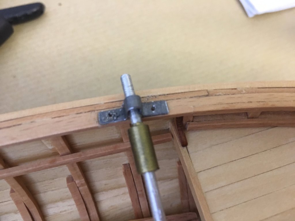
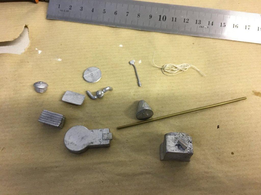
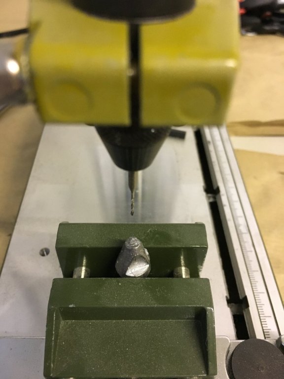
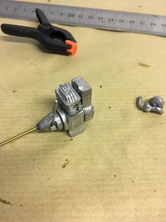
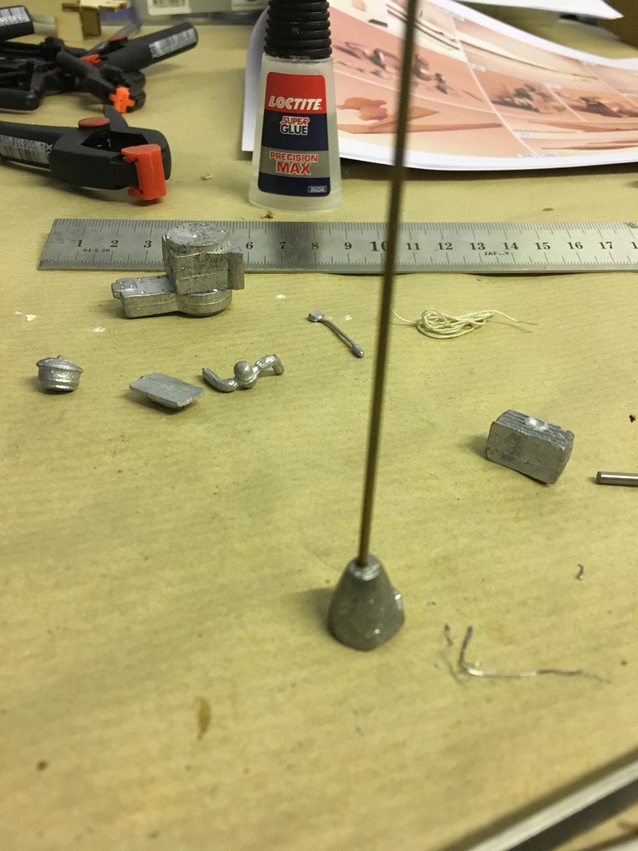
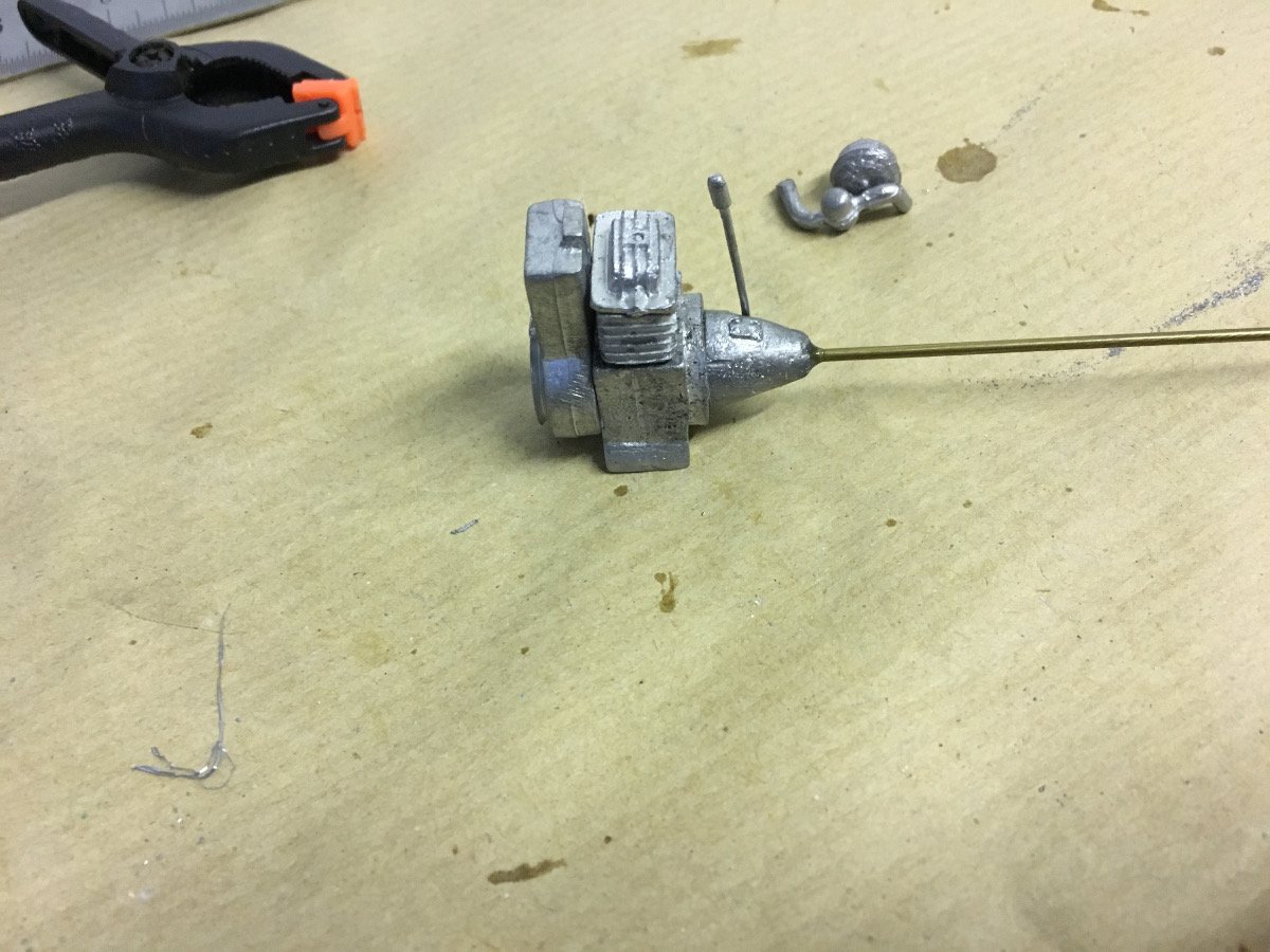
ENGINE:
Engine comes in cast metal. I have to say I was quite disappointed with the quality. Inaccurate parts with lots of burrs here and there. Besides, some parts (you will see in the later photos) were impossible to glue. The rod is supposed to go through all the way through the components but there was no hole in them and there was no way I would waste my drill bits trying to drill hole through the metal. So I just glued them using CA and only drilled a 2-3mm hole to stick the rod, which will go to the propeller. The two pieces you will see in the second last photo will not fit therefore I will just leave them out...


This is the status after these two days.
Thank you for watching.
/Aydin
-
Build day: 14
1,5 hours today, 35,5 hours in total.
Continuing with the handrails.
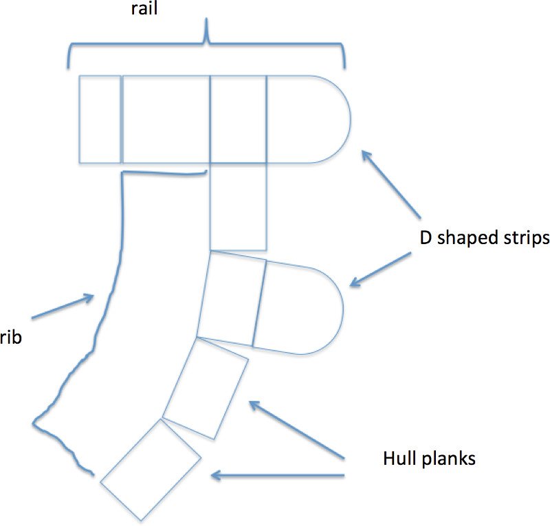
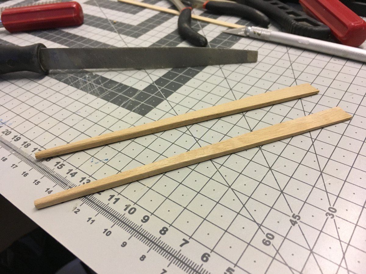
4 of the 2x2mm strips need to be rounded to a D shape. Two of them will be used on the outmost rails, 2 of them will be aligned approximately 1cm below the handrails, outside the, parallel to rails.
Below is a rough cross-section illustration of how the rails are formed:
Strips filed and sanded to D shape:
Gluing the two inner rail strips:
This is all for today. Next, I will glue the D shaped strips and sand all of them to level.
Thanks for watching.
-
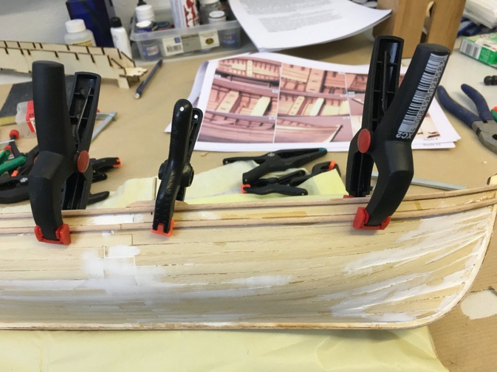
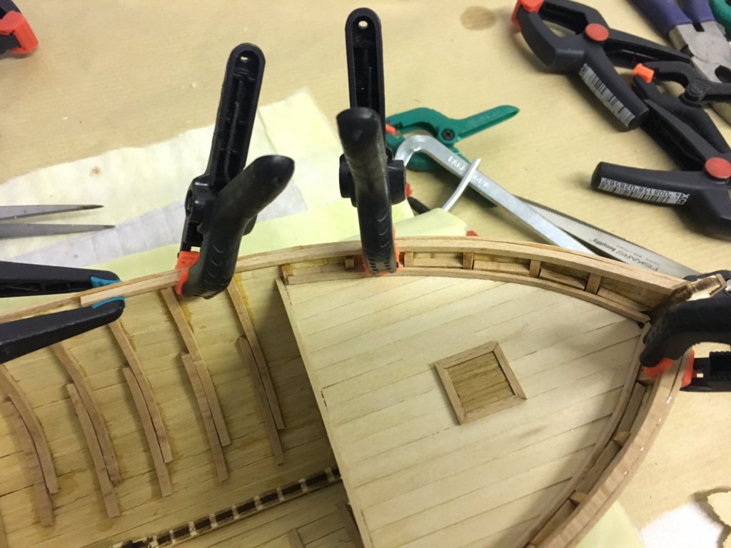
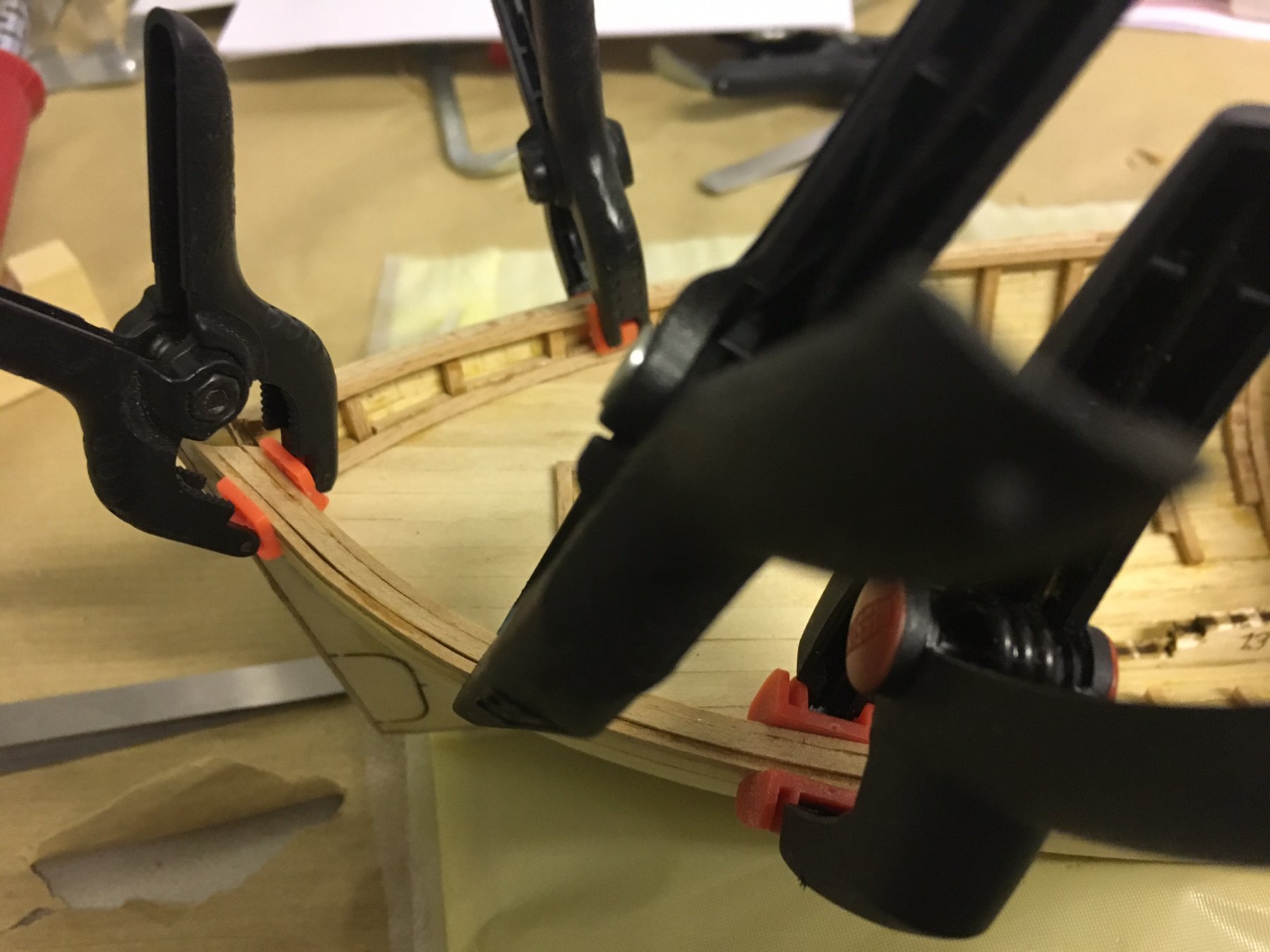
Next in line is adding the handrails. Instead of struggling with bending a single wide strip, they will be constructed by gluing thinner strips together.
It starts with 1x2mm walnut strips glued right over the topmost hull plank, following it flush. (This is the part I finished today)
Next, more walnut strips (2x2mm) will be added both inside and outside of this strip.
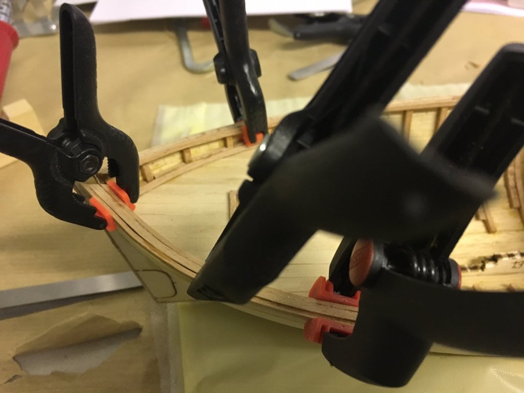
First strip being glued:
First line of strips completed.

This is the status after today.
Thanks for watching!
/Aydin

-
-


1:24 Istanbul diorama - OcCre
in Non-ship kit reviews
Posted
Looks like they have corrected it on Occre website visuals:
https://www.occre.com/diorama/diorama-istanbul.html
I believe your post has made an impact")