


aydingocer
-
Posts
858 -
Joined
-
Last visited
Content Type
Profiles
Forums
Gallery
Events
Posts posted by aydingocer
-
-
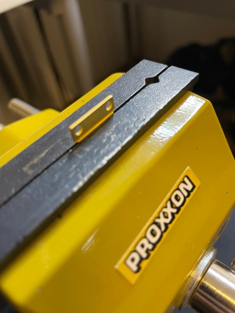
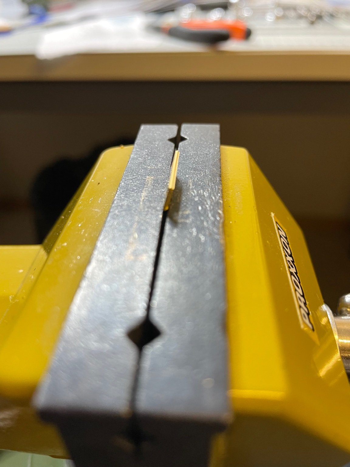
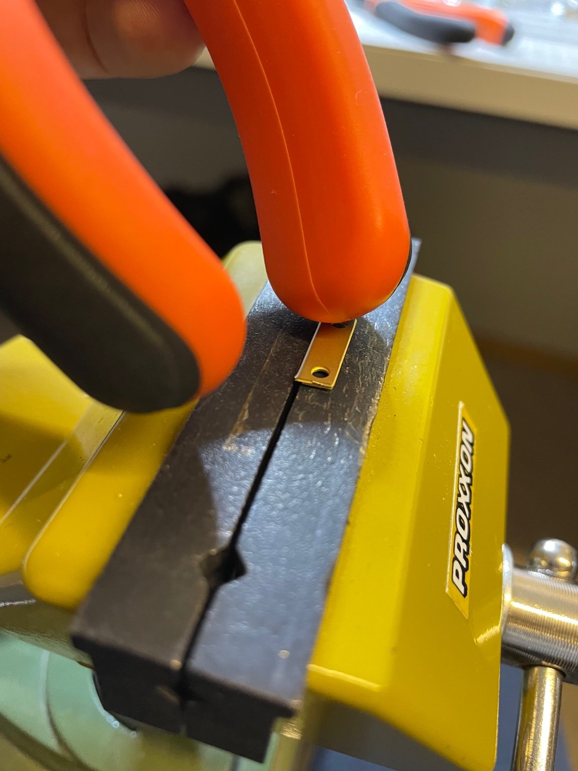
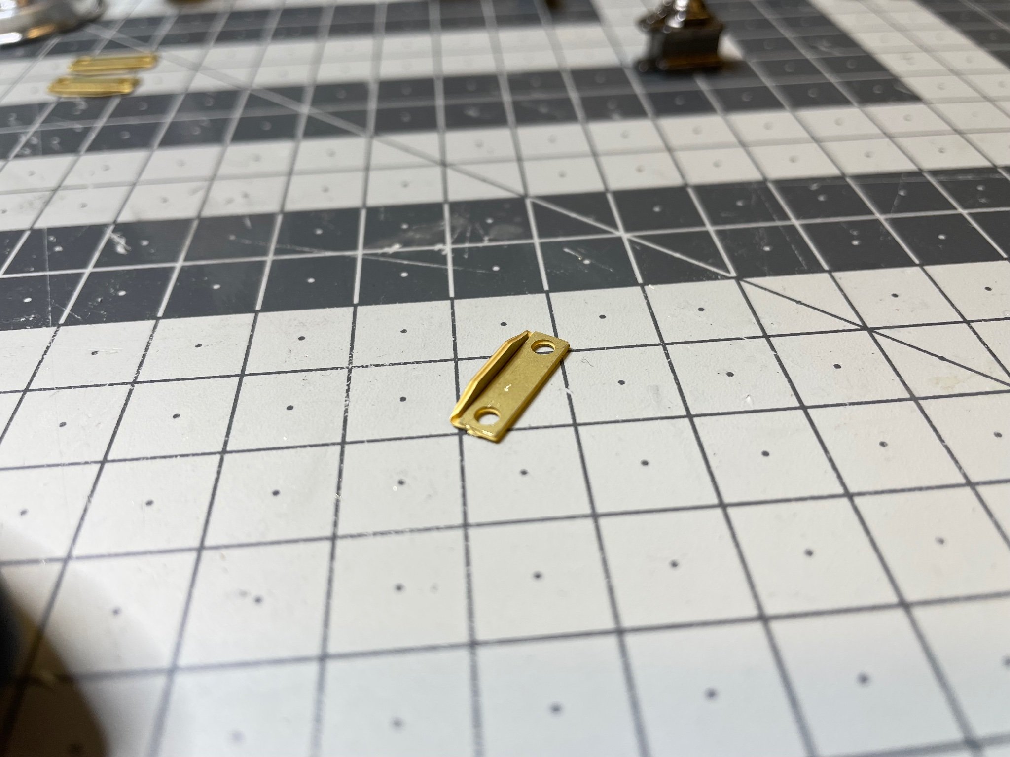
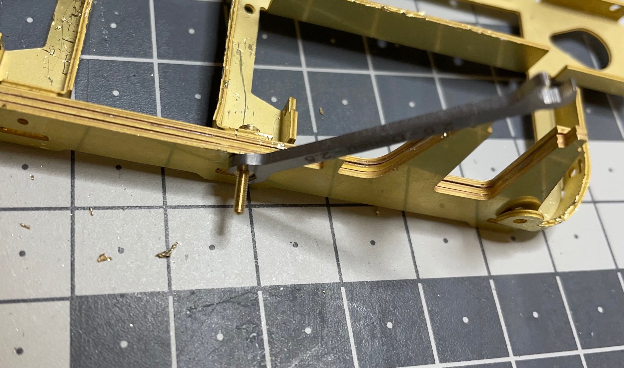
BUILD DAY 7: 2,5 hrs (TOTAL: 23 hrs)
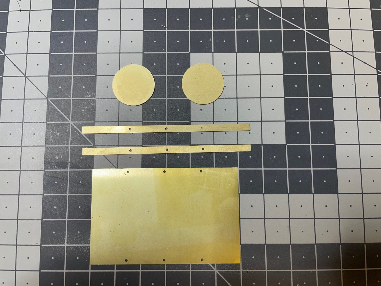
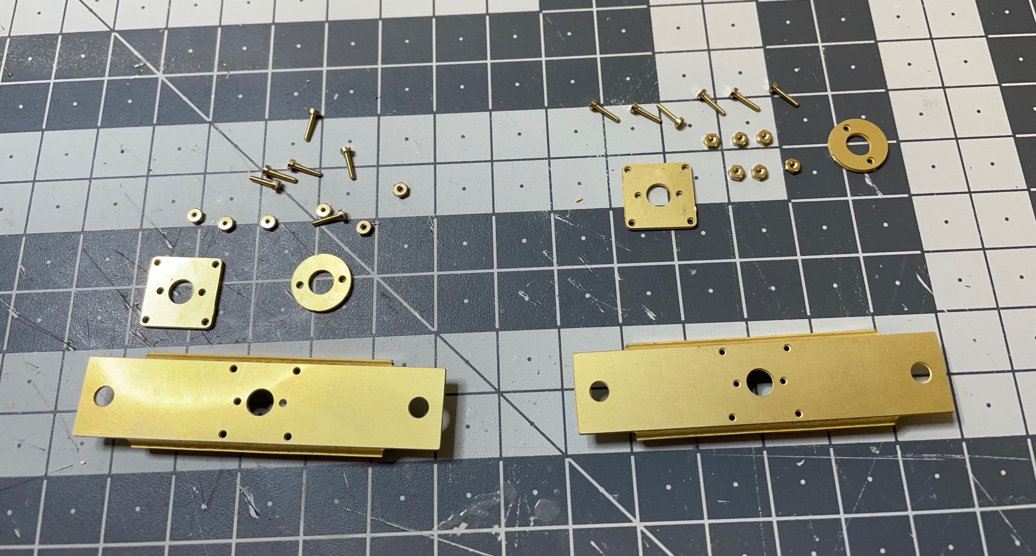
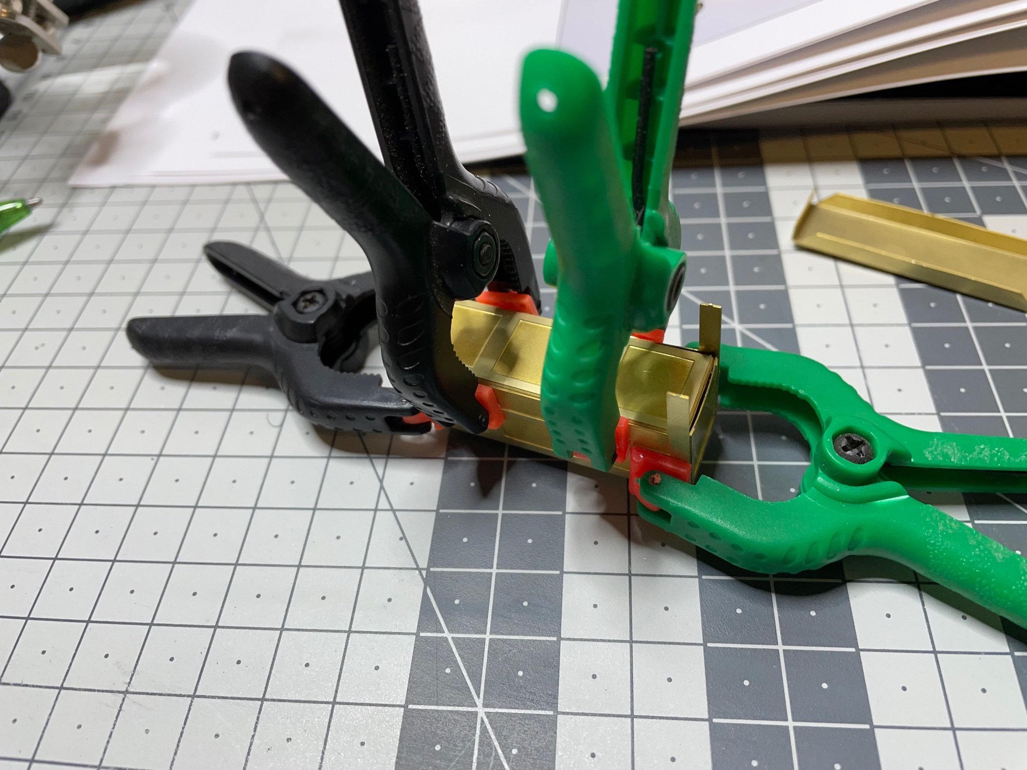
Figures 99-102: This is how I bend this kind of small and thick brass parts. I used plier's handle as a hammer. A soft rubber hammer would be a more proper tool for this purpose.


-
Amati has replied to my request, they are sending the missing part. Fingers crossed 🙂.
- Egilman, popeye the sailor, Canute and 5 others
-
 8
8
-
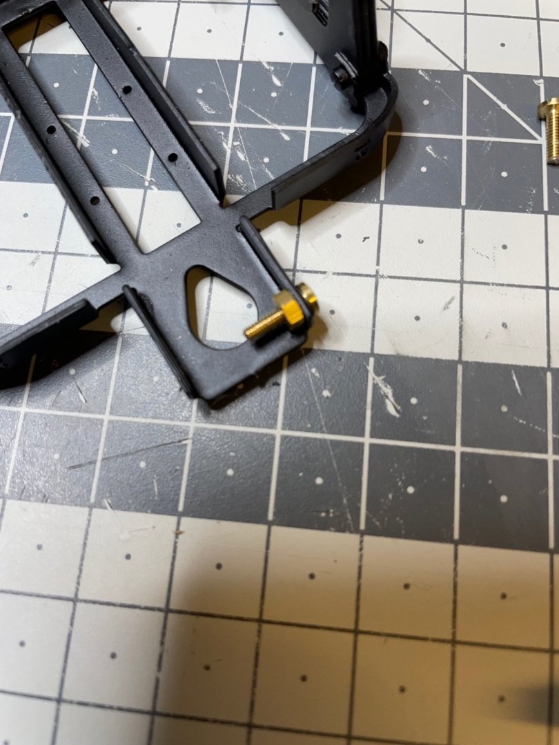
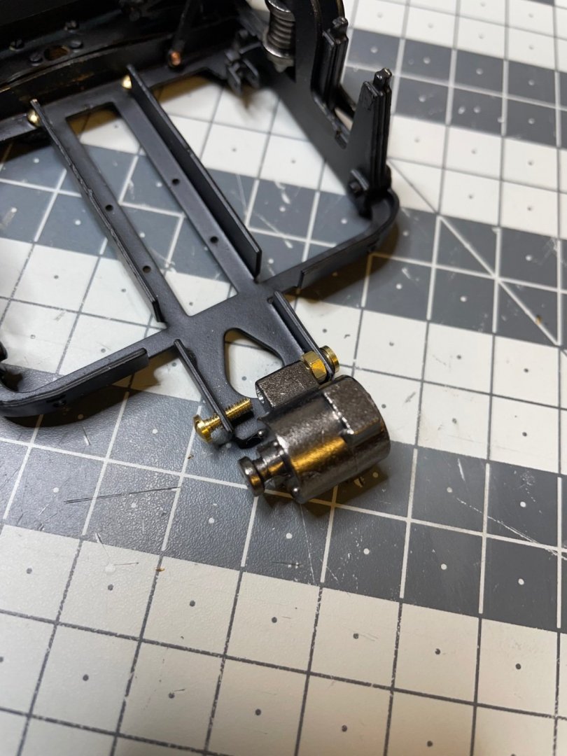
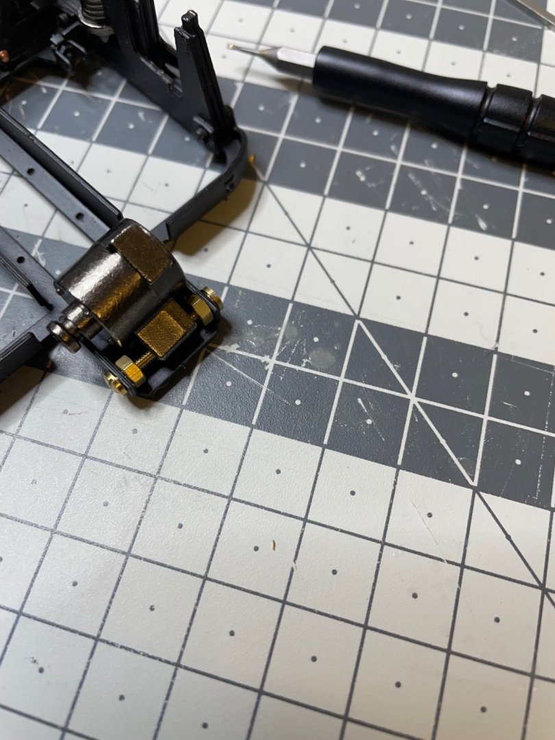
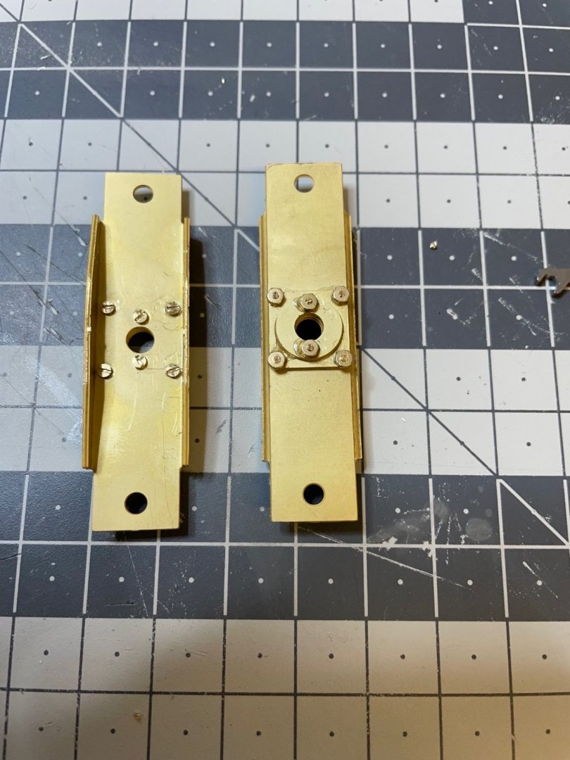
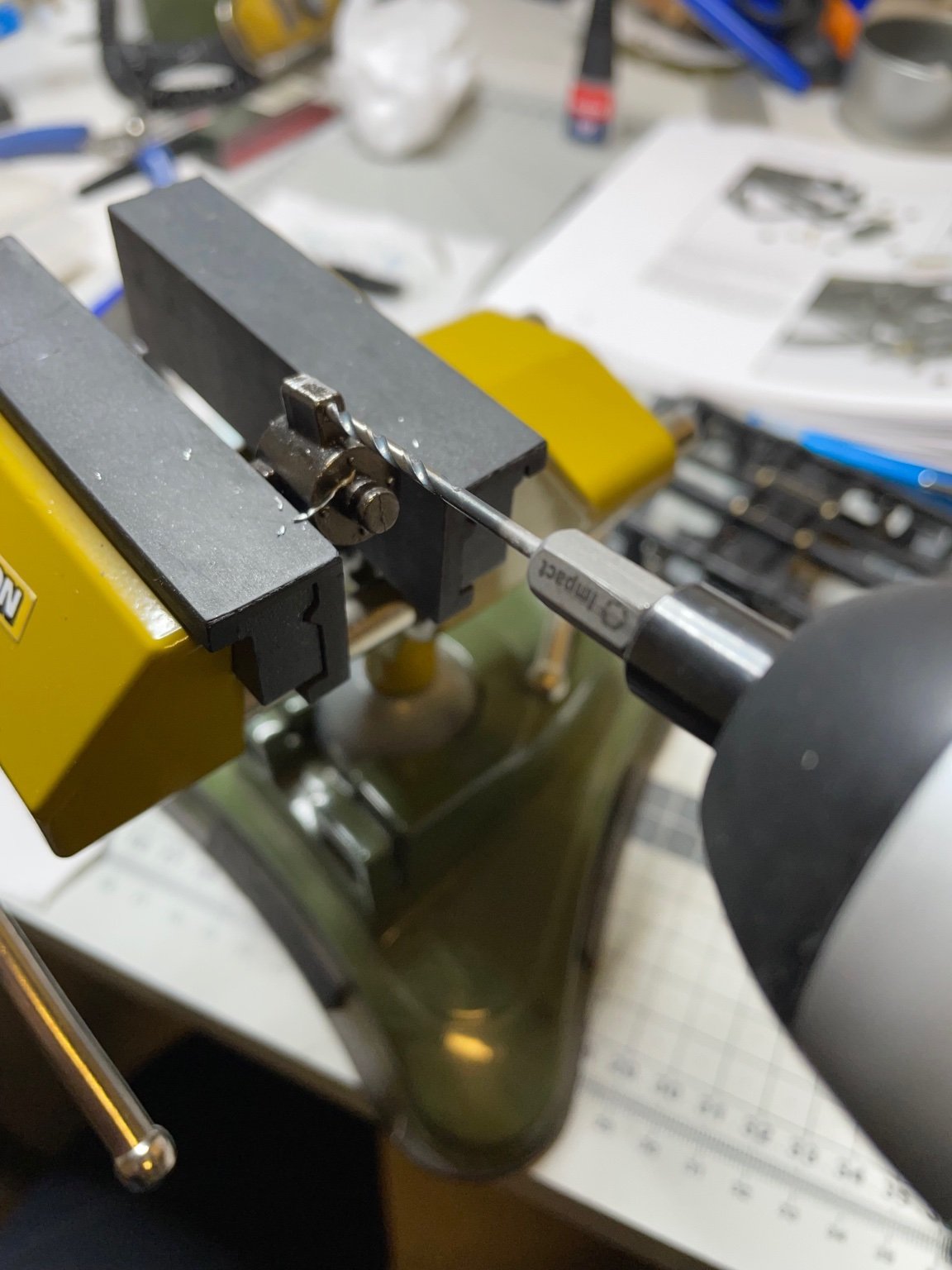
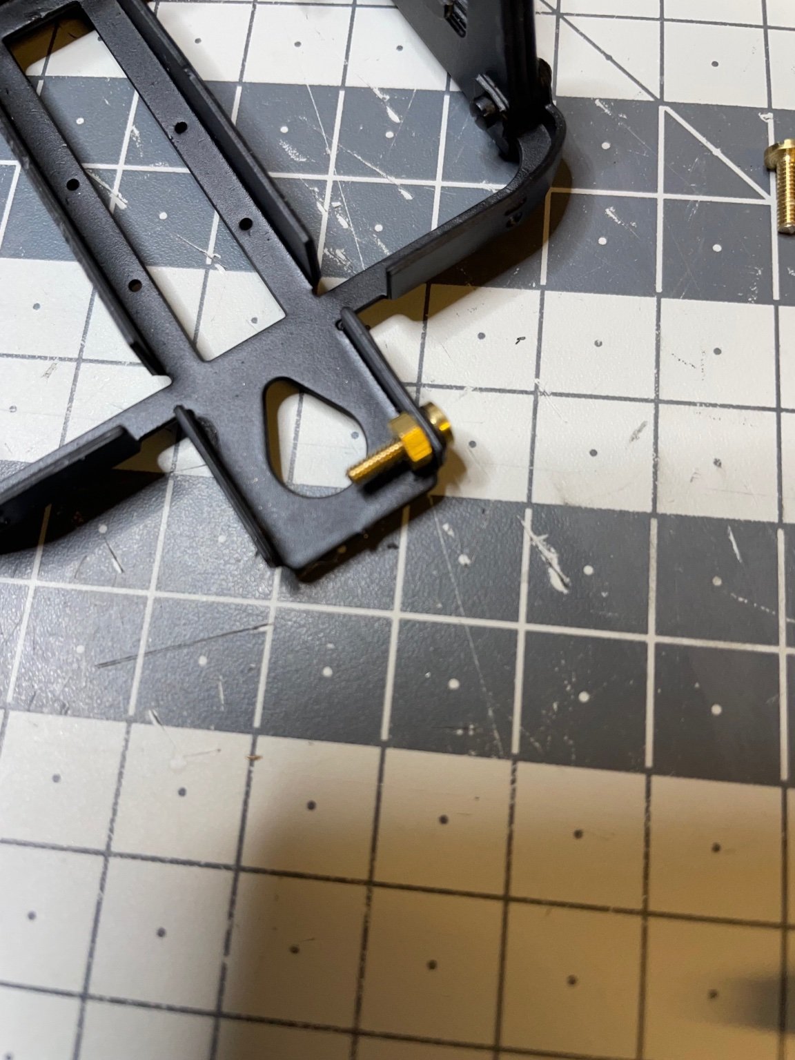
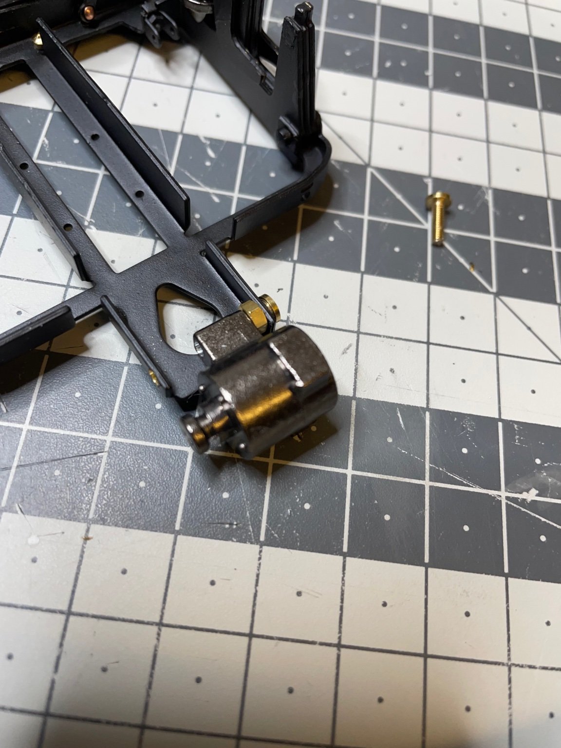
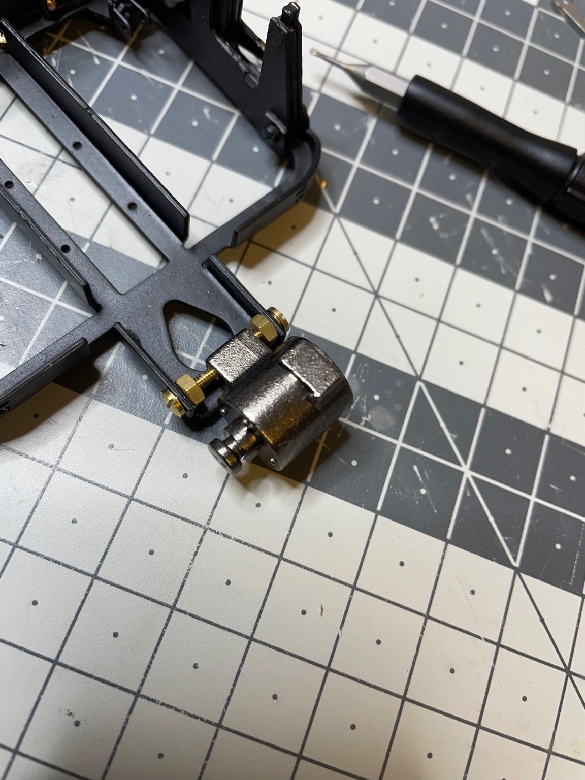
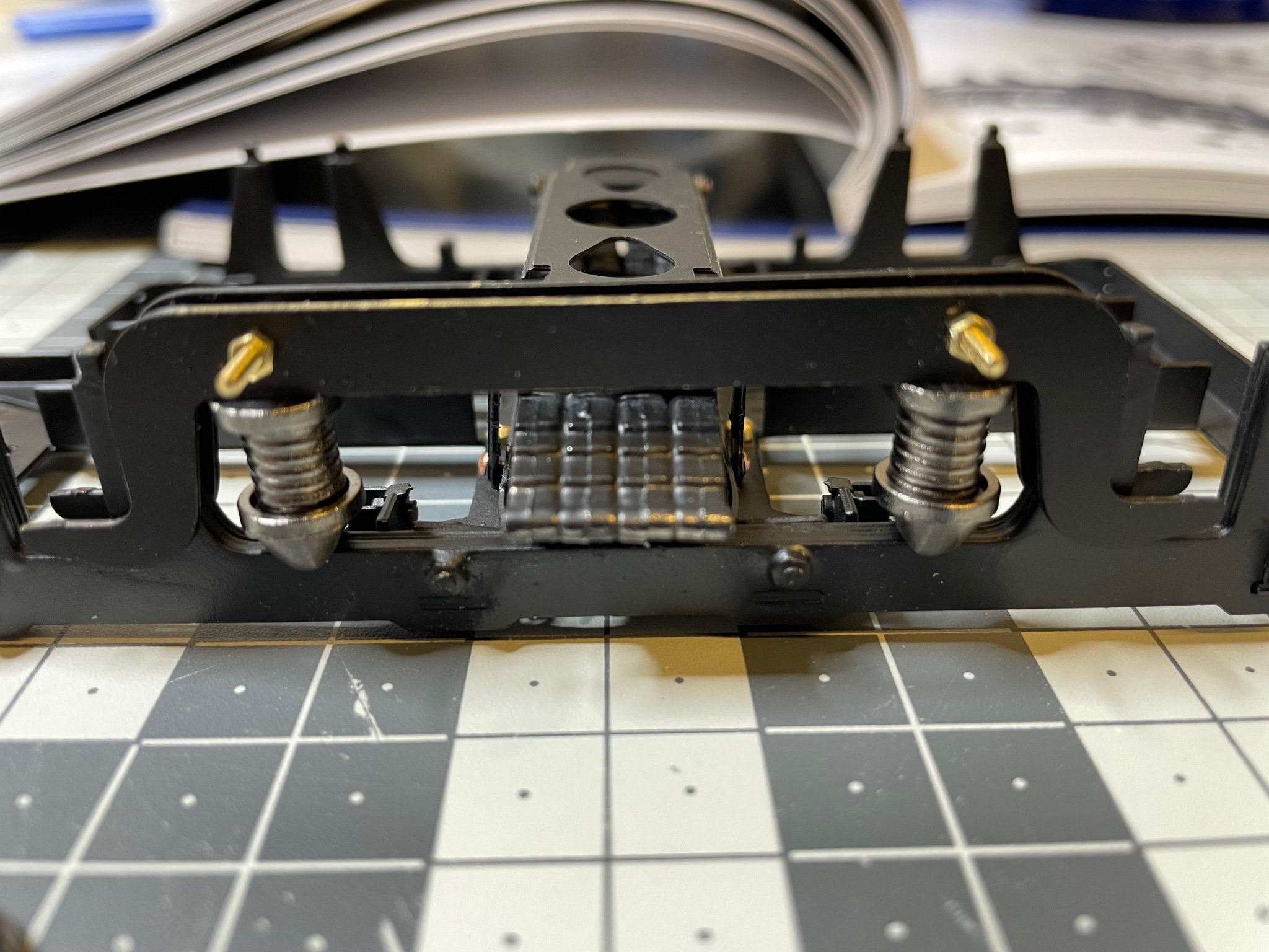
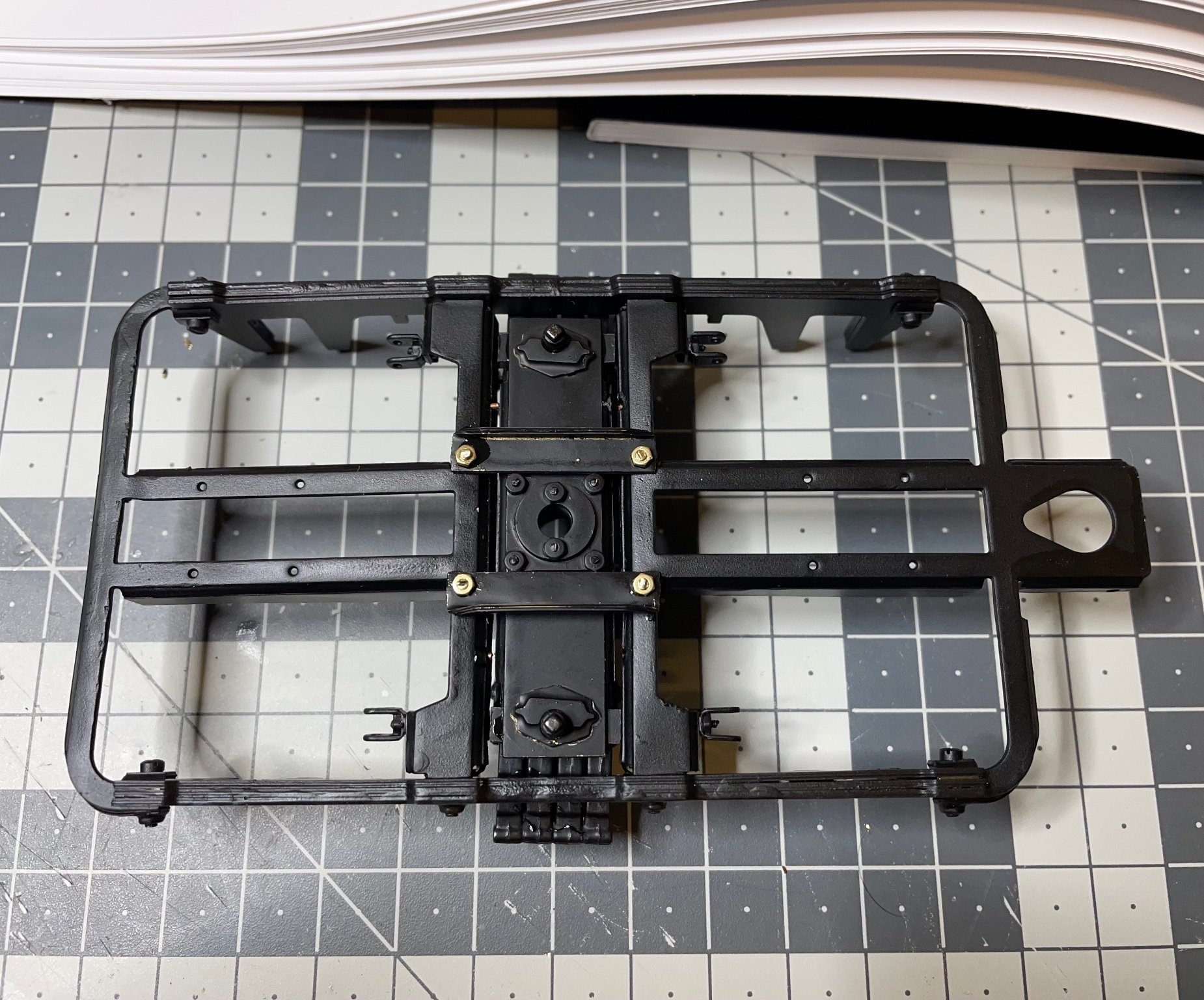
Installation of the dynamo. This part is only on one of the frames.
Figure 91: Dynamo is installed using 2 bolts and nuts, which need to be shortened to size (10mm and 7,5mm) and must fit in the dynamo. Well, except once again they don't. Hence, drill. 🤣

Figures 92-98: Showing the process of dynamo installation.


That's all for today!
Thanks for watching!
-
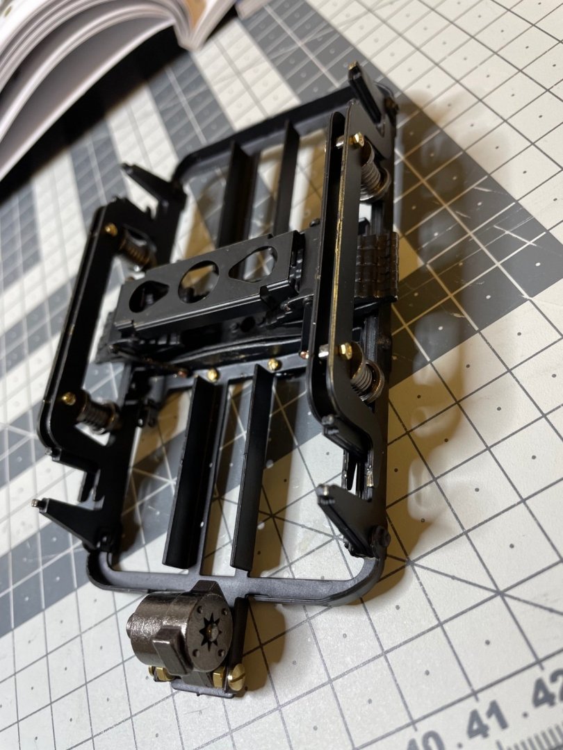
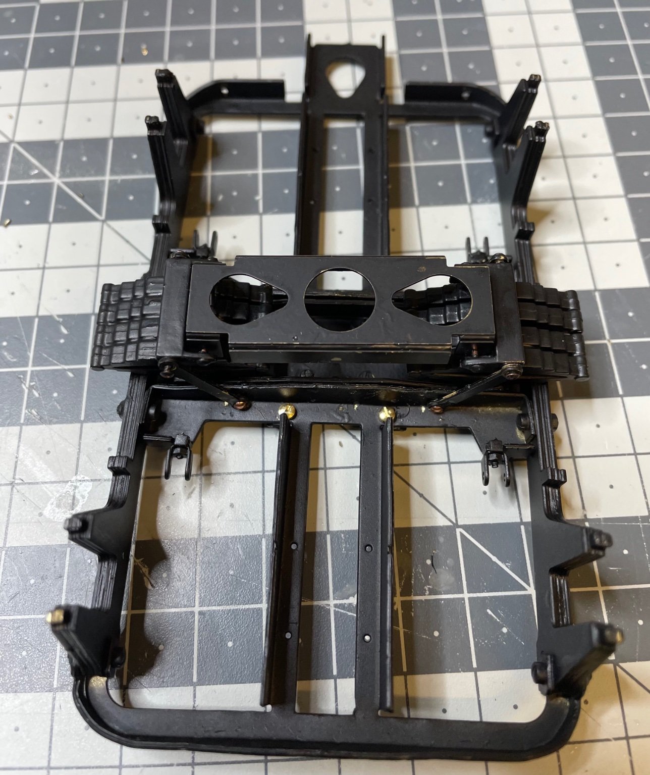
Figure 87: The so called "struts" and springs. This will be the structure where the wheels will sit on, later.

Figure 88: Painted in matt black as usual
The springs consist of 3 parts to be glued together. But I choose a bit different order than in the instructions, to ensure accurate alignment:
- First I glued the two parts which will be on the side of the struts (like in Figure 89 below),
- Then screwed them to the struts
- Inserted the 3rd part of the spring structure to the frame
- Finally placed the struts on top od that 3rd part.Figure 89:

Figure 90: Now everything looks perfectly aligned.

-
Figure 85: Suspension structure painted and mounted in place.

Figure 86: How to mount the suspension structure to the frame. See the brass rods connecting on left and right side. Altogether four of them. They also use copper rivets to allow the suspension to move.

-
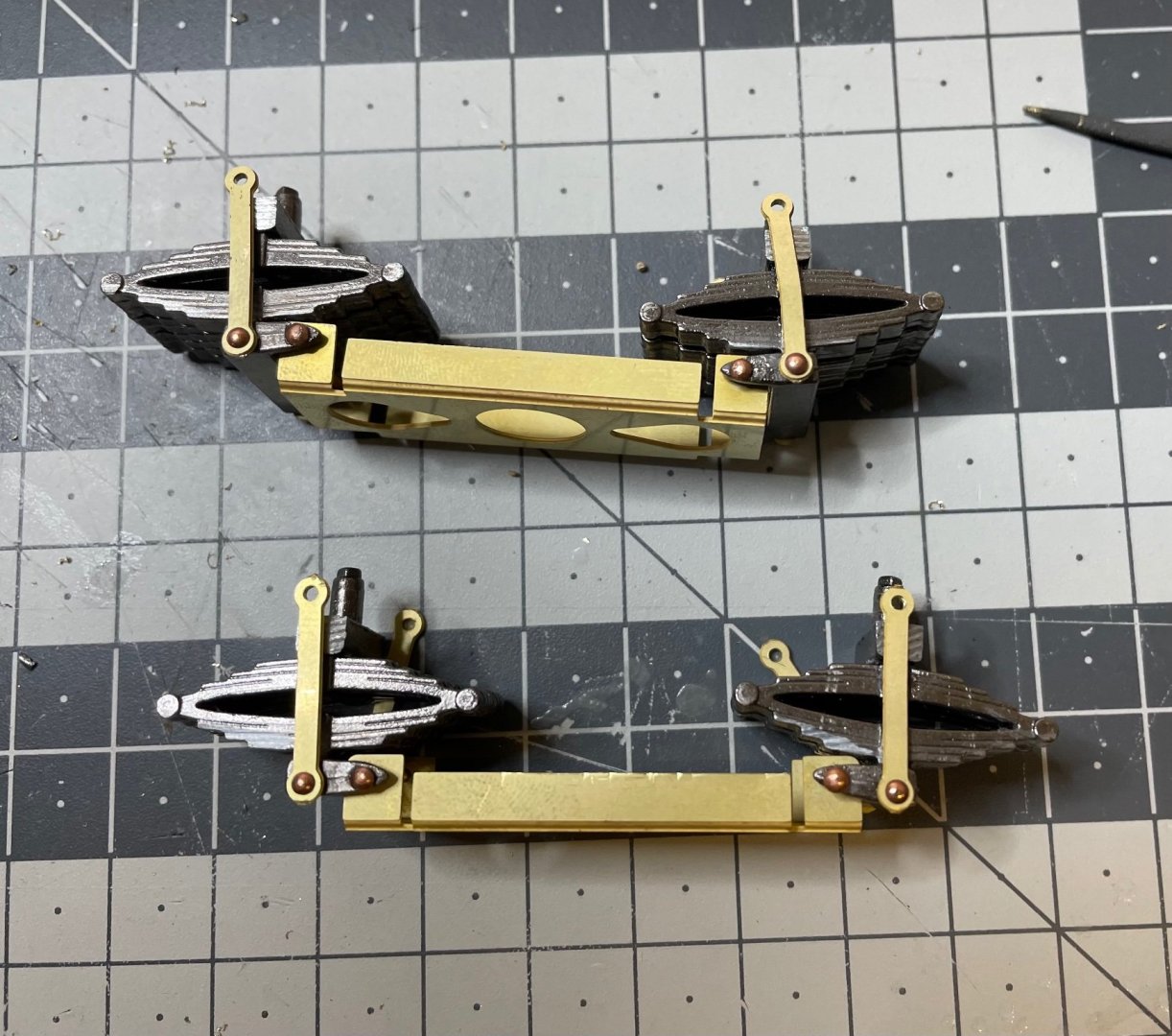
Figure 84: The moving structure is ready. The parts are mounted using copper rivets, not bolts, to allow them rotate freely.
-
More photos on the assembly process.
Figure 82: Dry fit on the springs, for aligning the small parts on the left side of the picture, to be glued on either side of the brass component.
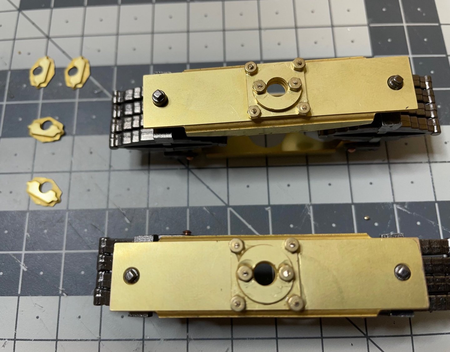
Figure 83: More drilling. The holes are simply too small. They are almost there only for a reference of the correct location :).
-
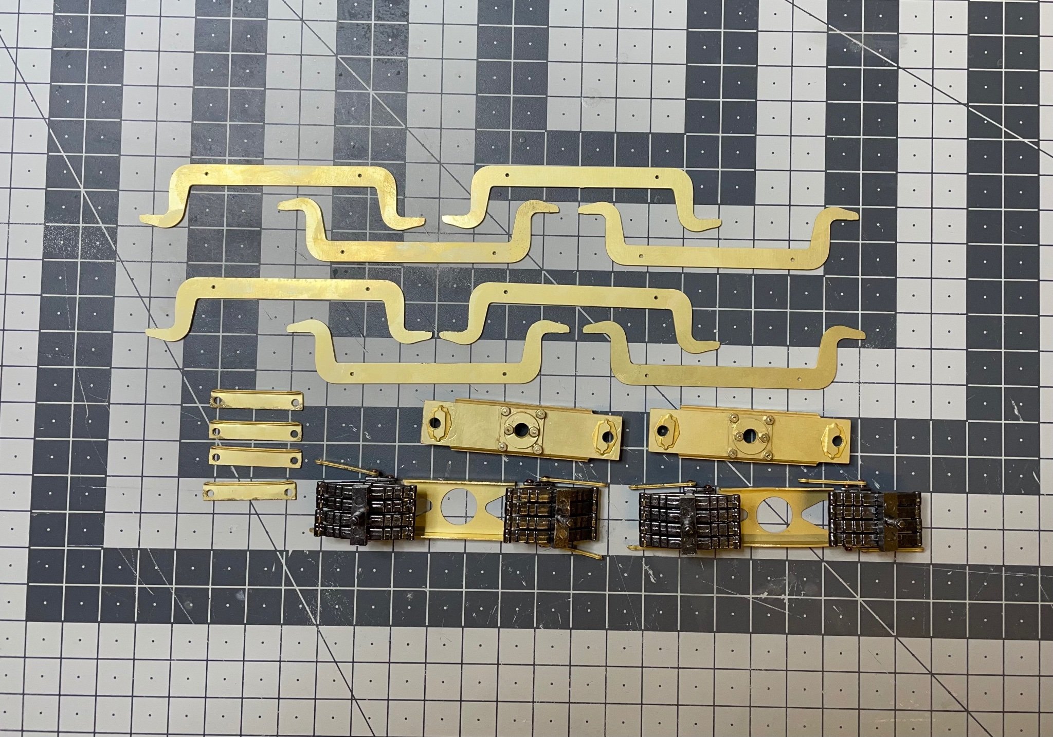
Figure 79: Brass parts for the suspension.
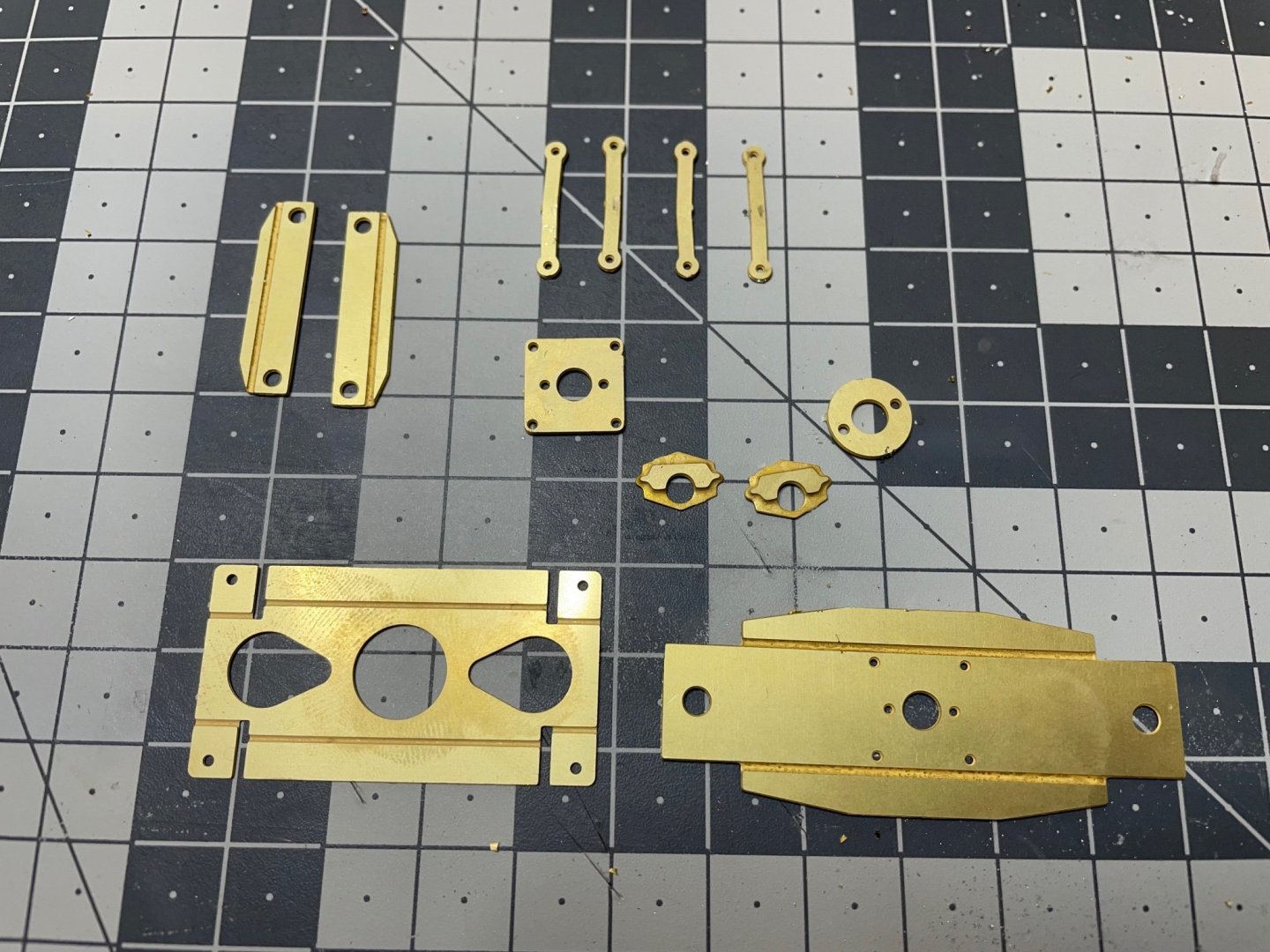
Figure 80: Bent as instructed.

Figure 81: Parts mounted and fixed using 1,5mm bolts.
- Canute, mtaylor, thibaultron and 4 others
-
7
-
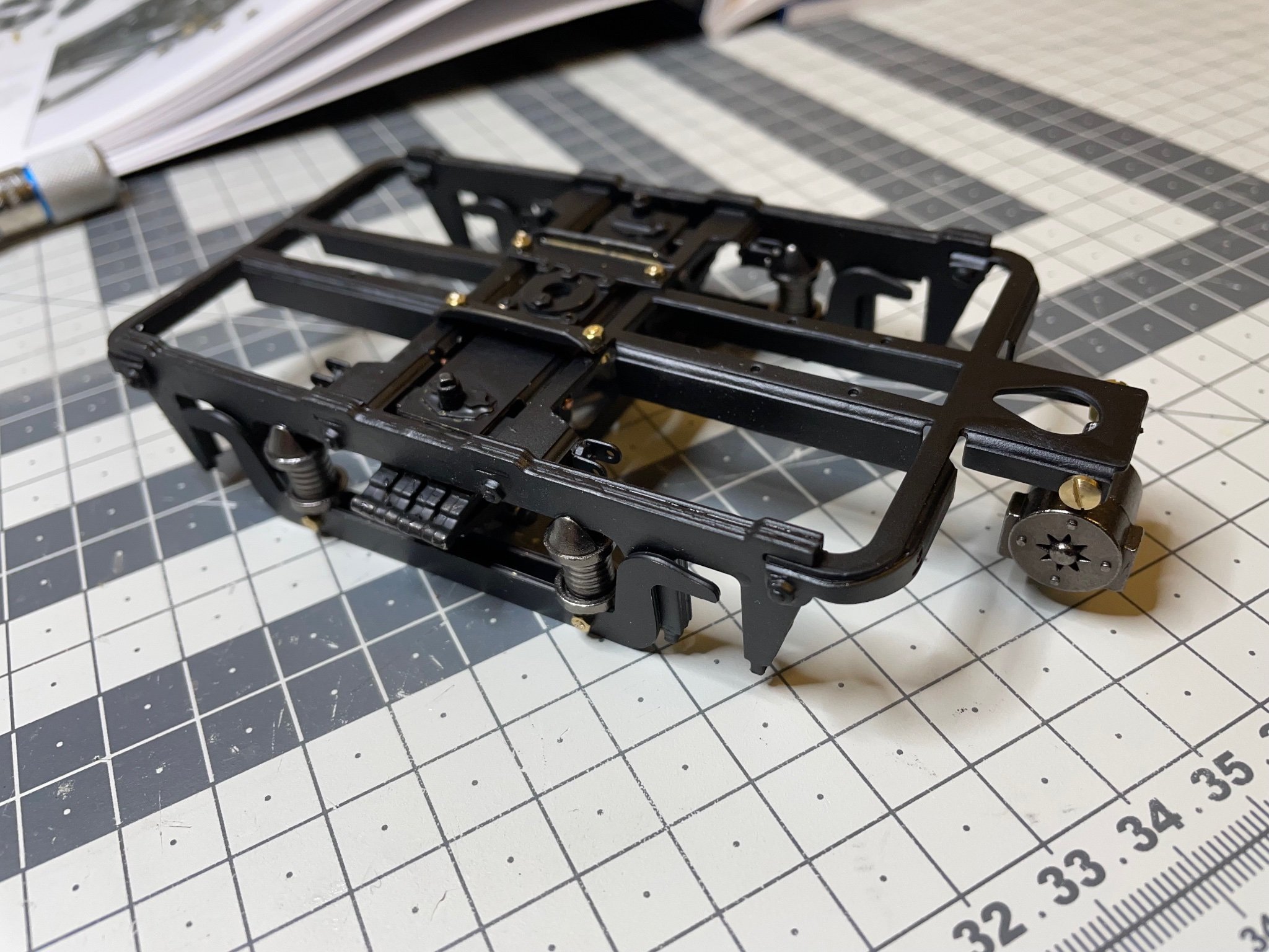
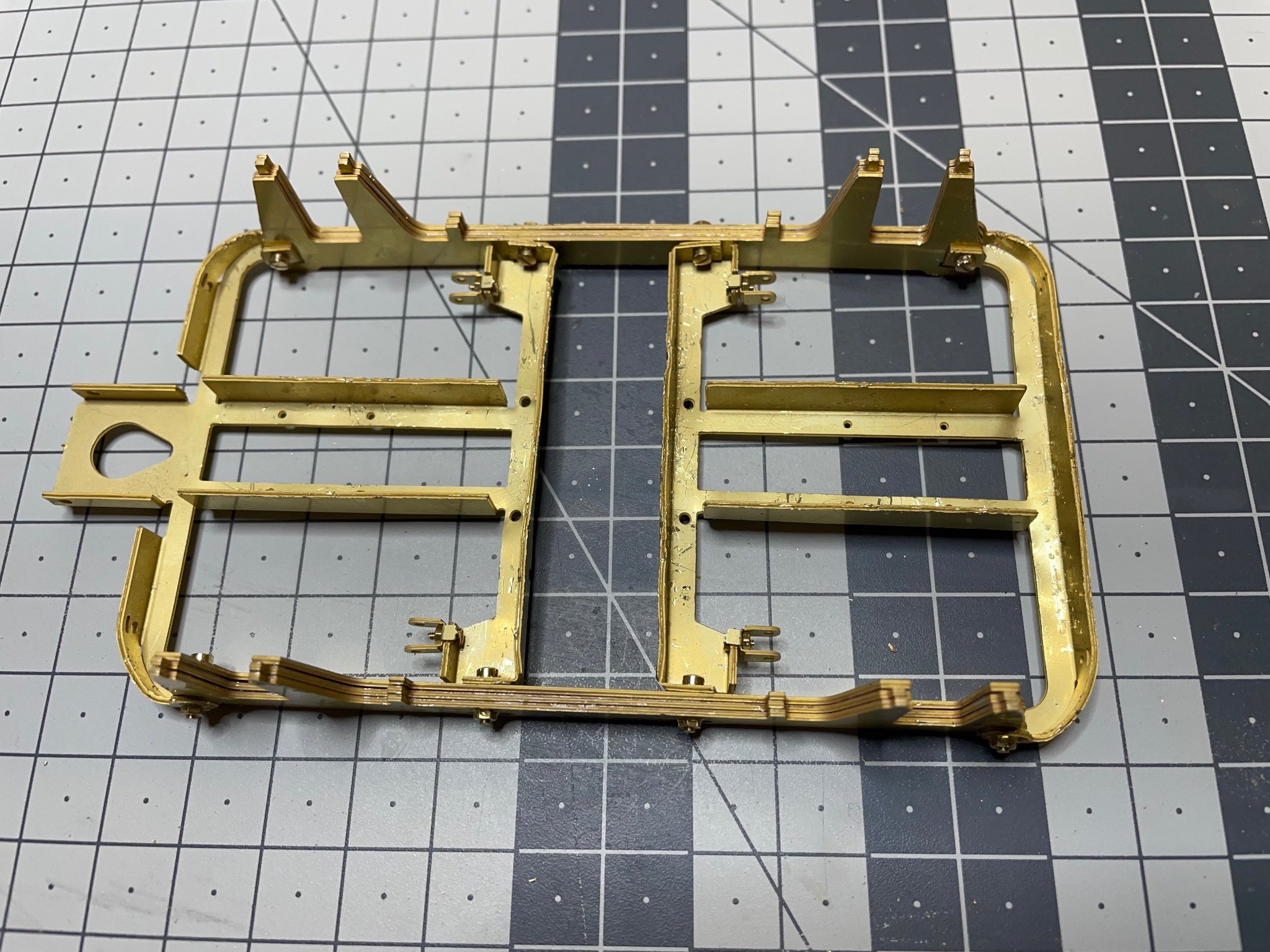
BUILD DAY 6: 3 hrs (TOTAL: 20,5 hrs)
Continuing with bogies. Now the frames are ready, it is time to fill them.
Note: The manual is instructing to finish one of the bogies first and then repeat the almost identical steps to build the second one. I will not follow this approach fully, nor a parallel building progress. Instead I decided to go with a "hybrid" approach. I build some pair of components at the same time where it looks more convenient and keep them aside until I build the second bogie.
Next on the line is the suspension structure. There will be two of these.
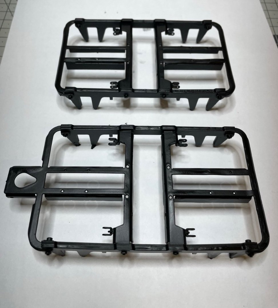
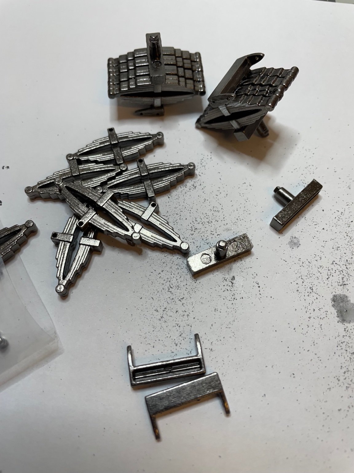
Figure 77: Die cast parts.
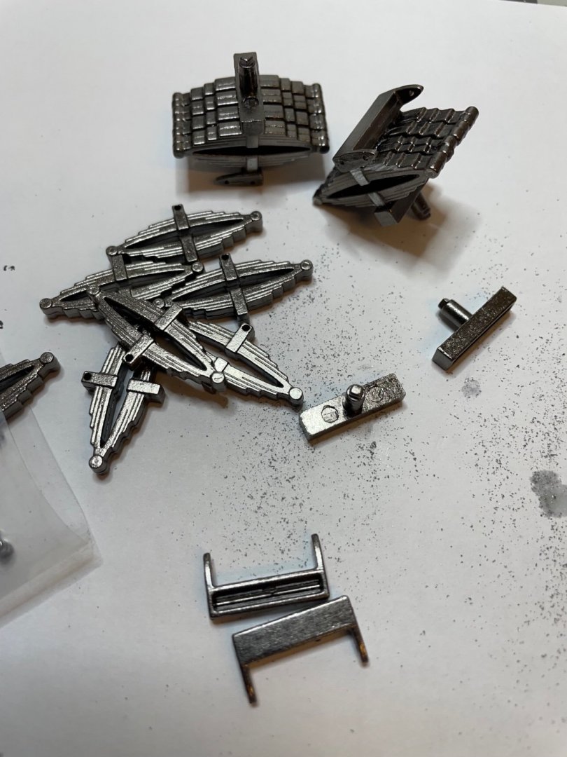
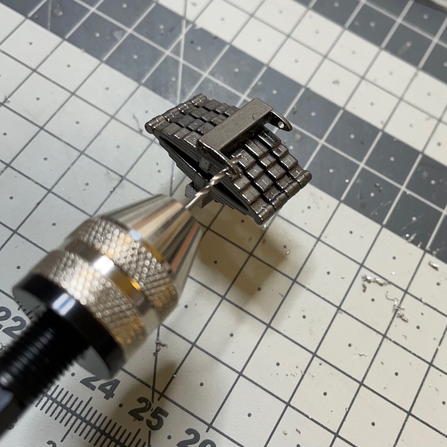
Figure 78: You will need to enlarge almost every hole by drilling, in order to fit the bolts conveniently. Do not try to push/pull the bolts with pliers or other tools to pass them through the holes, their pitches will get ruined very easily and the bolt will be impossible to use. Better open a wider hole and just insert the bolt smoothly.

- Canute, thibaultron, wefalck and 4 others
-
7
-
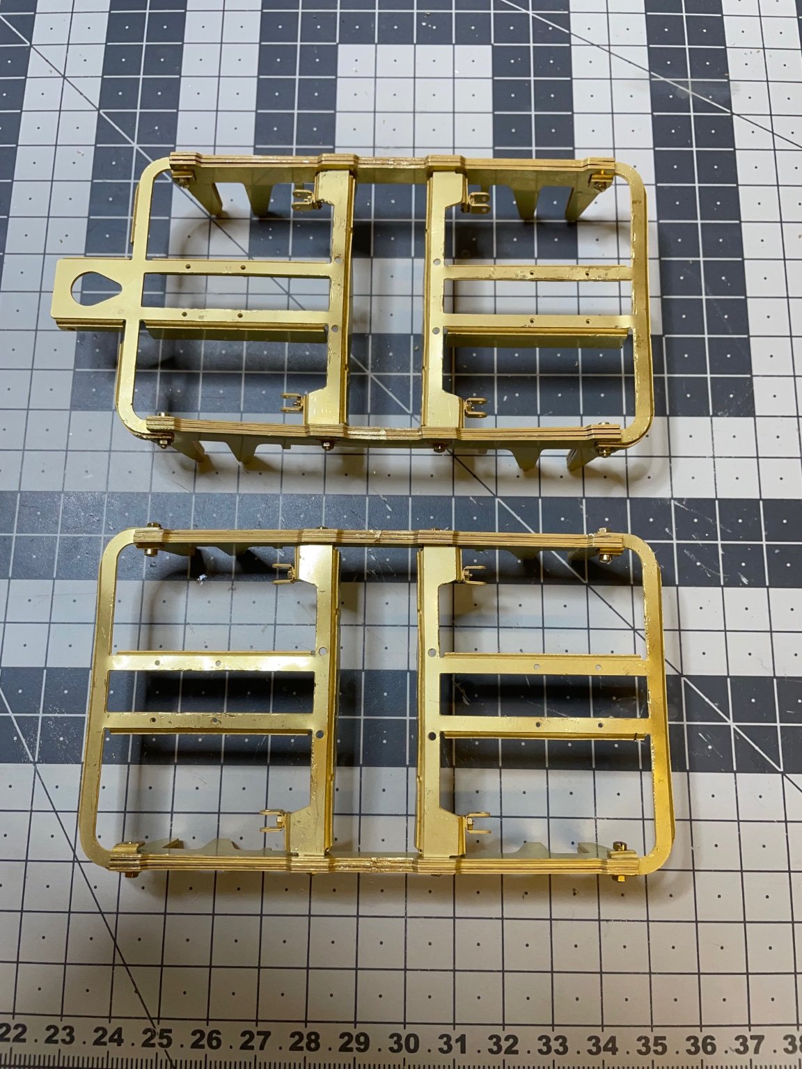
Figure 76: Bogies' frames painted.
- 1 layer matt black spray primer
- 1 layer matt black spray paint.
-
Figure 75: Followed the similar procedure for the other bogie. Now there are two of them.
Bogies are ready for first painting. There are still a lot to be done on them, but as per the instructions now they are at a stage ready for painting.

That's all for today!
Thanks for watching! -
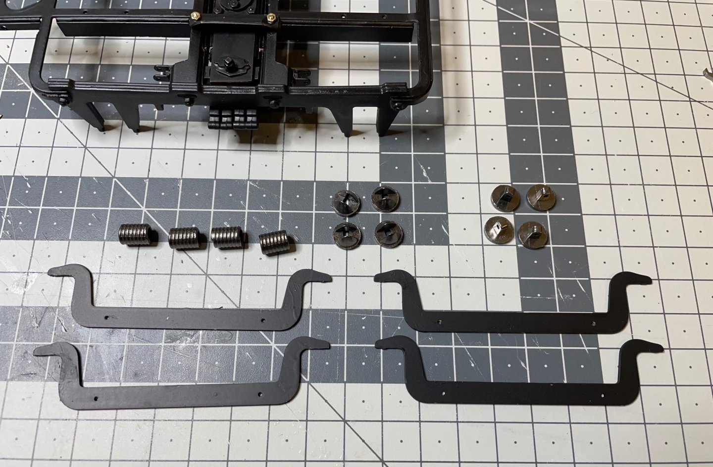
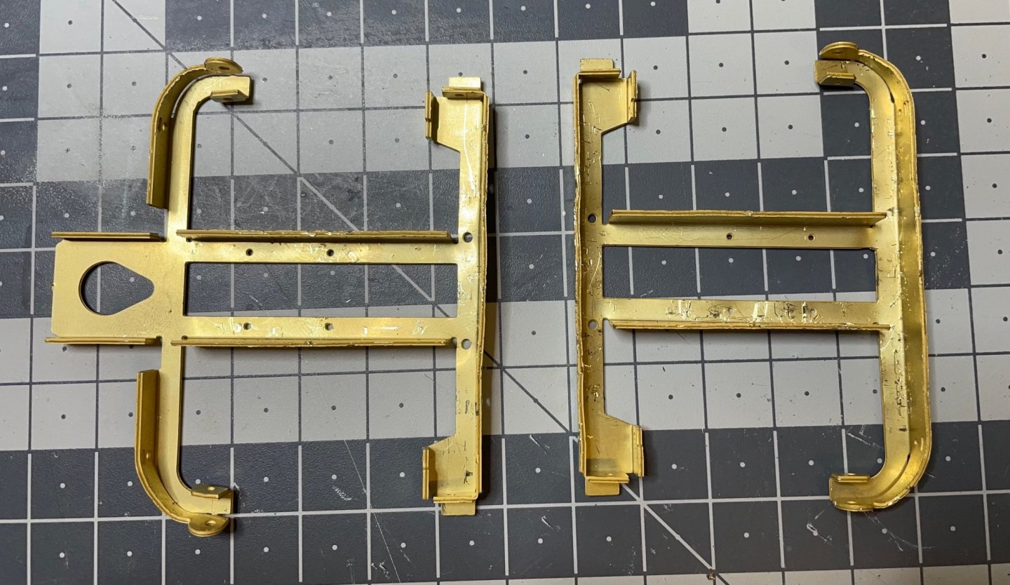
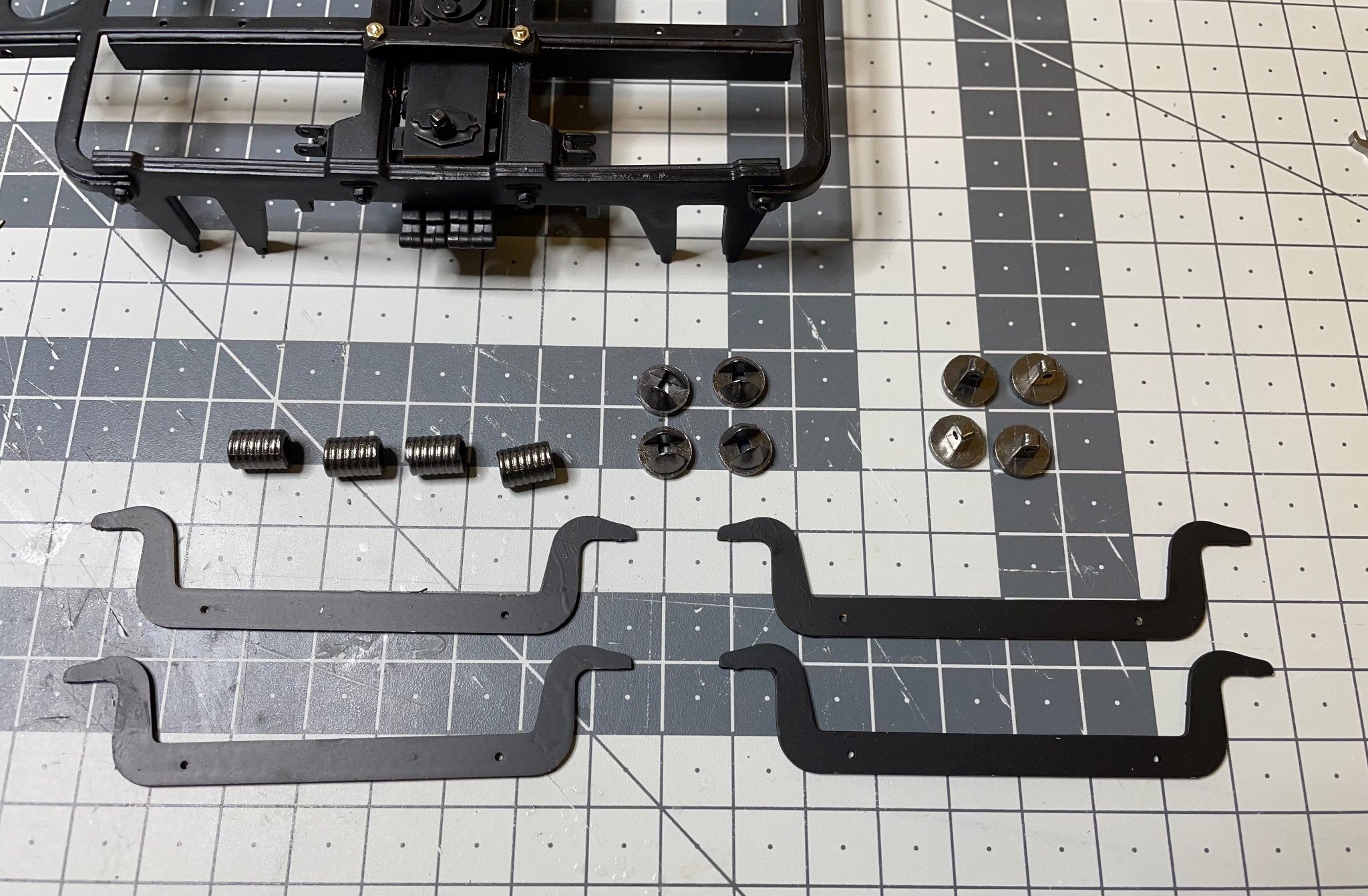
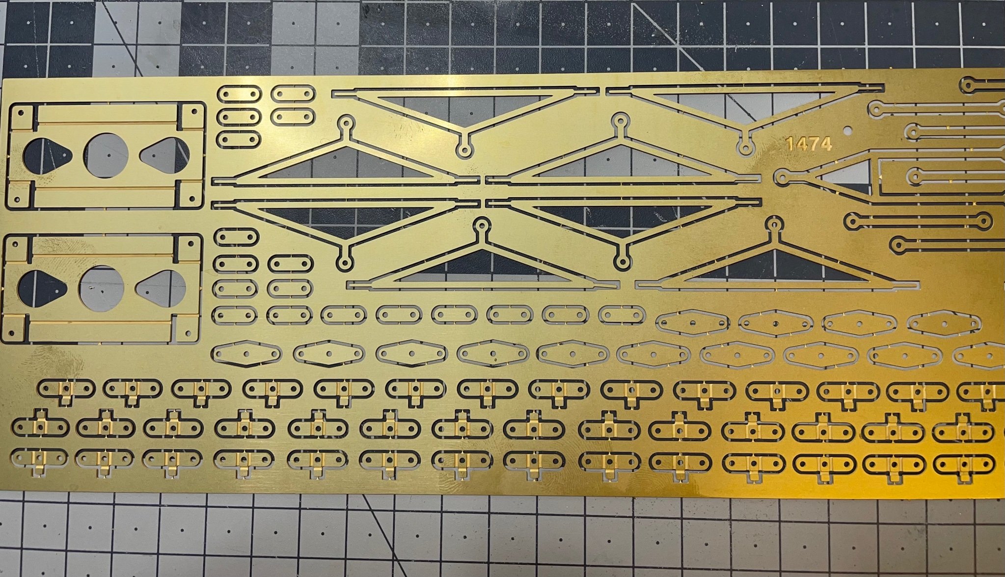
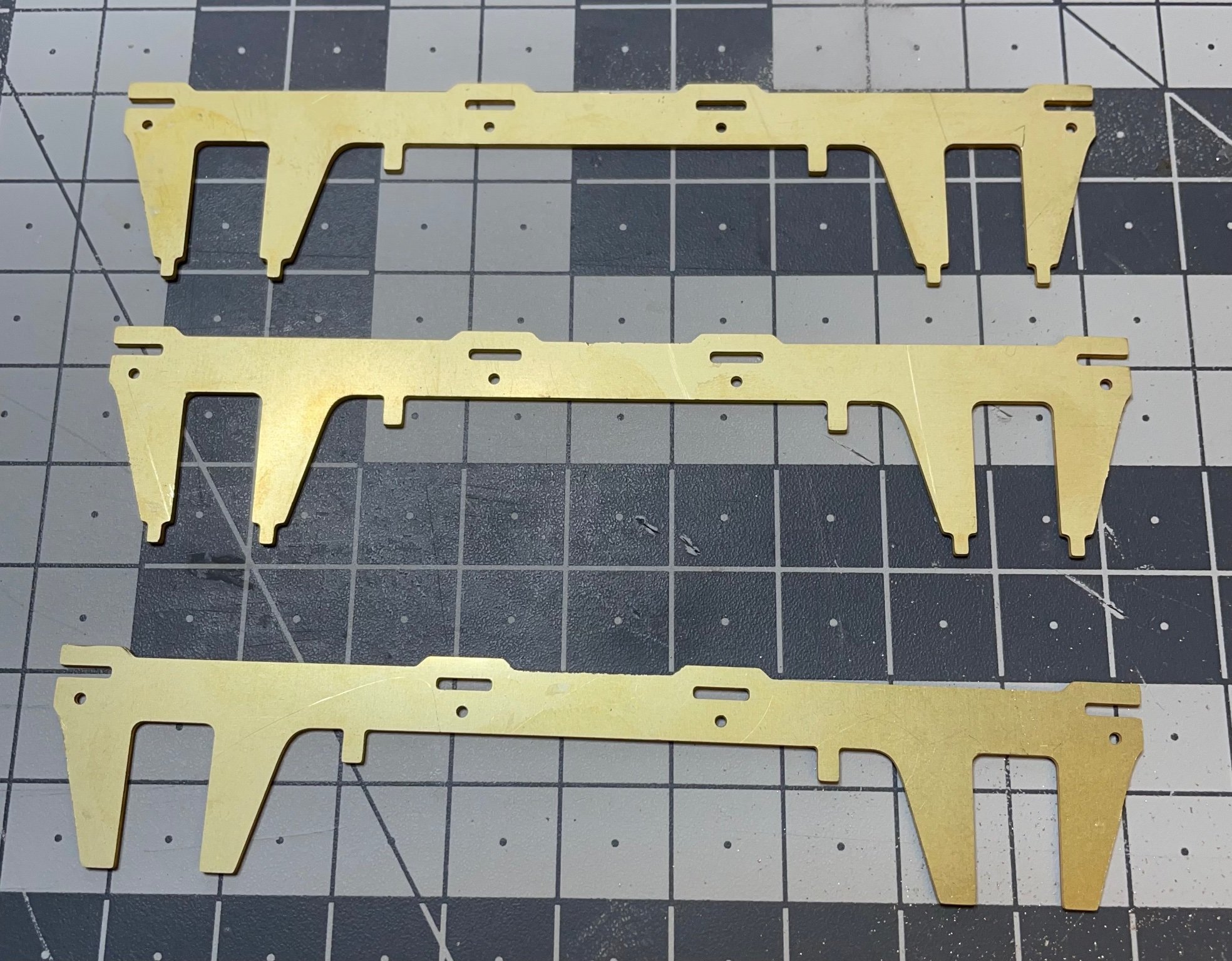
Figure 69: Brackets, on the brass sheet.

Figure 70: Removed 16 of them from the sheet. 8 of them are to be bent different than the other 8. Some will be used at a later stage.
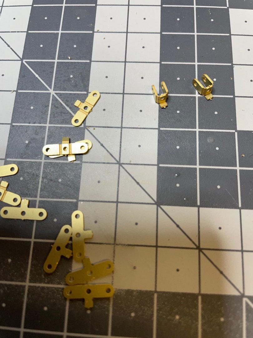
Figure 72: Bent the parts as instructed.
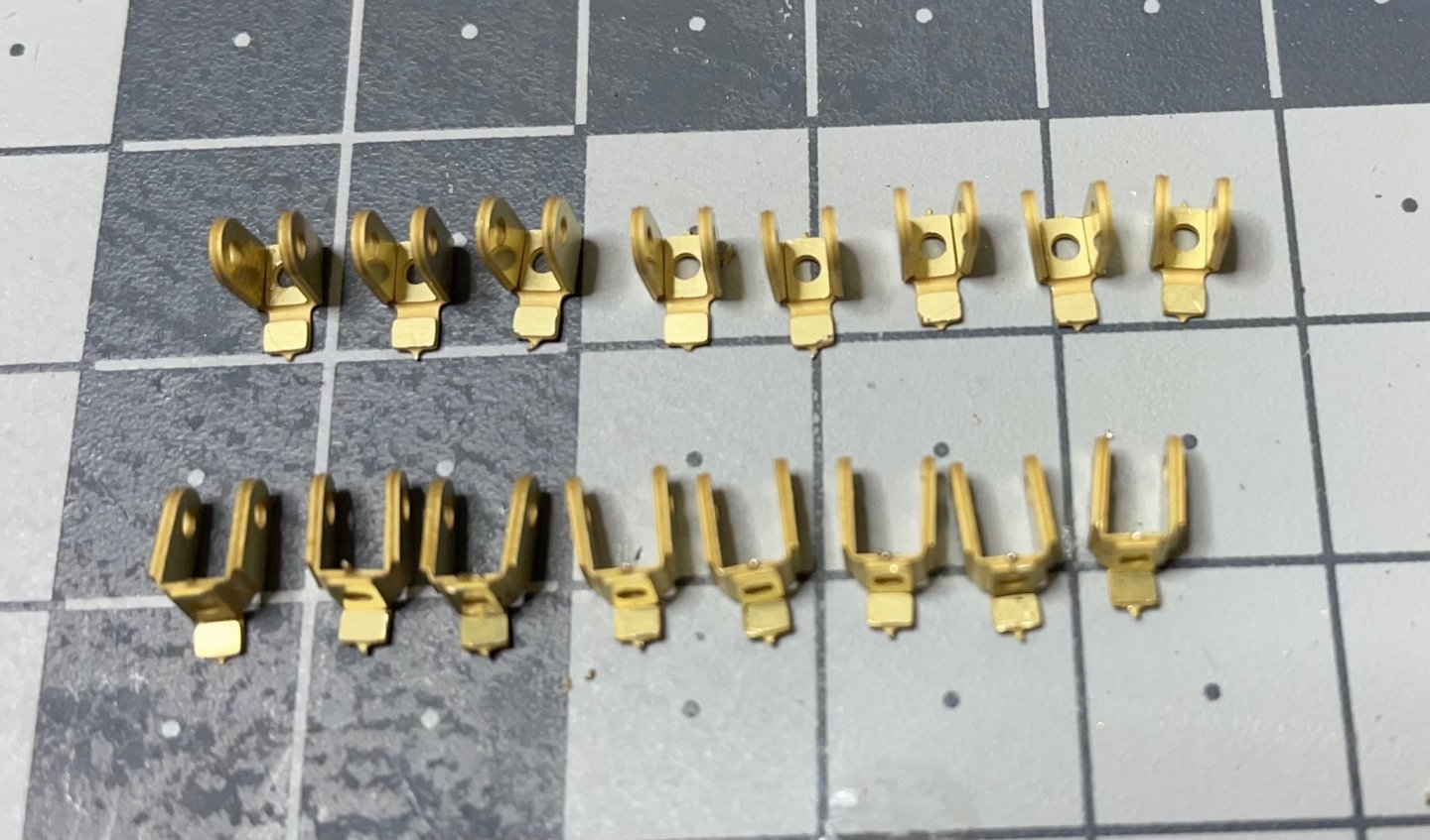
Figure 73: The brackets are in place.

-
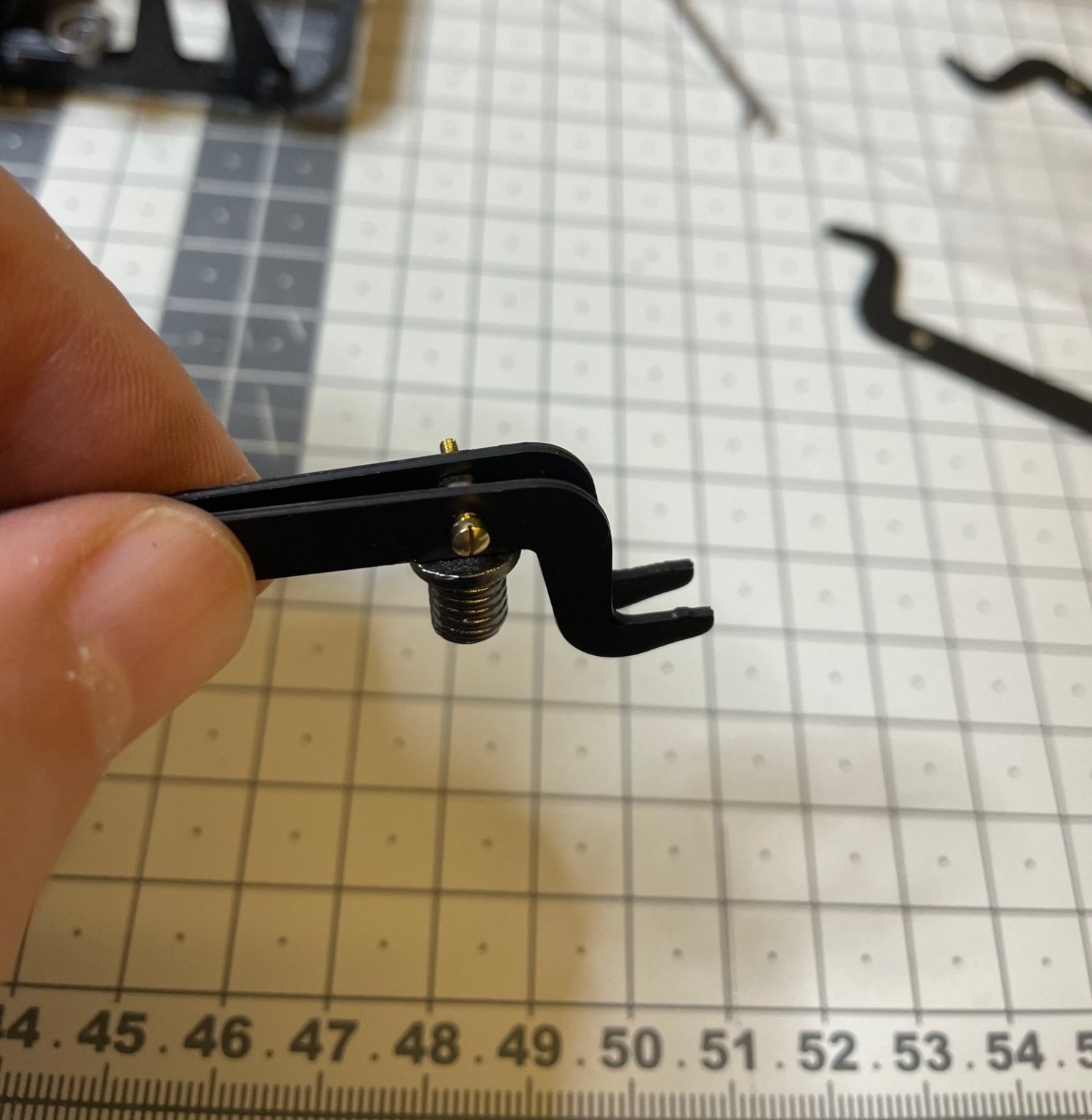
Figure 63, 64: Legs, formed of 3 pieces glued with super glue. 2 identical parts and on different. Pay attention to glue correctly.

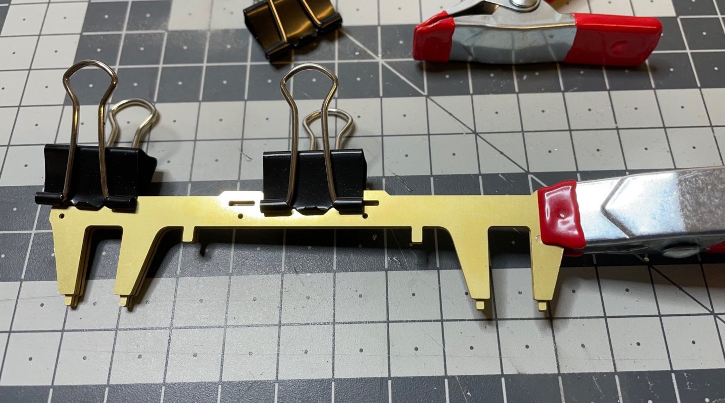
Figure 65: Legs in place. Dry fit.

Figure 66: My best friend of the day. A 2,5mm miniature hex wrench. Without it, I don't know what I 'd do.
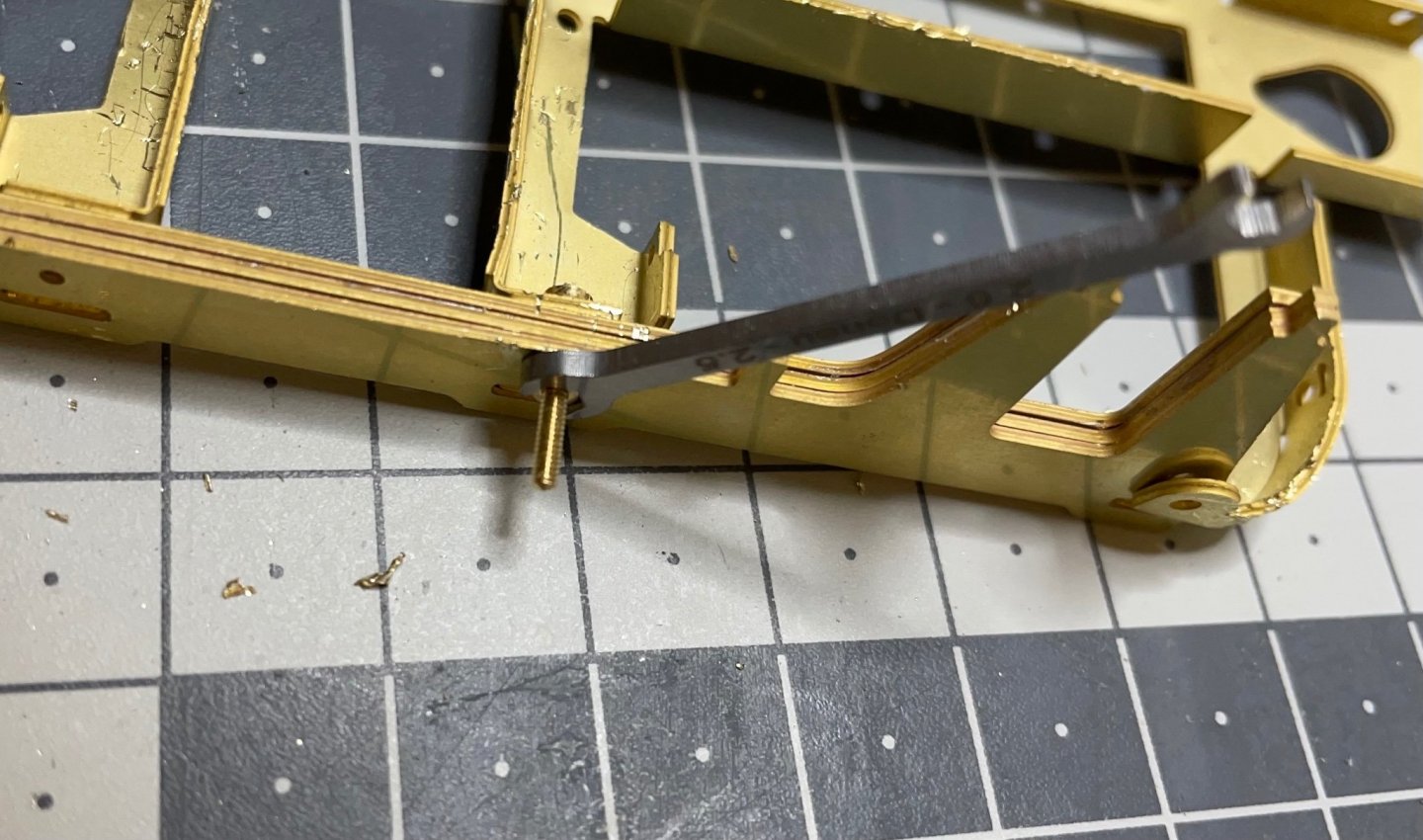
Figure 67, 68: First set of fixing screws in place. They will be trimmed later.
-
BUILD DAY 5: 6,5 hrs (TOTAL: 17,5 hrs)
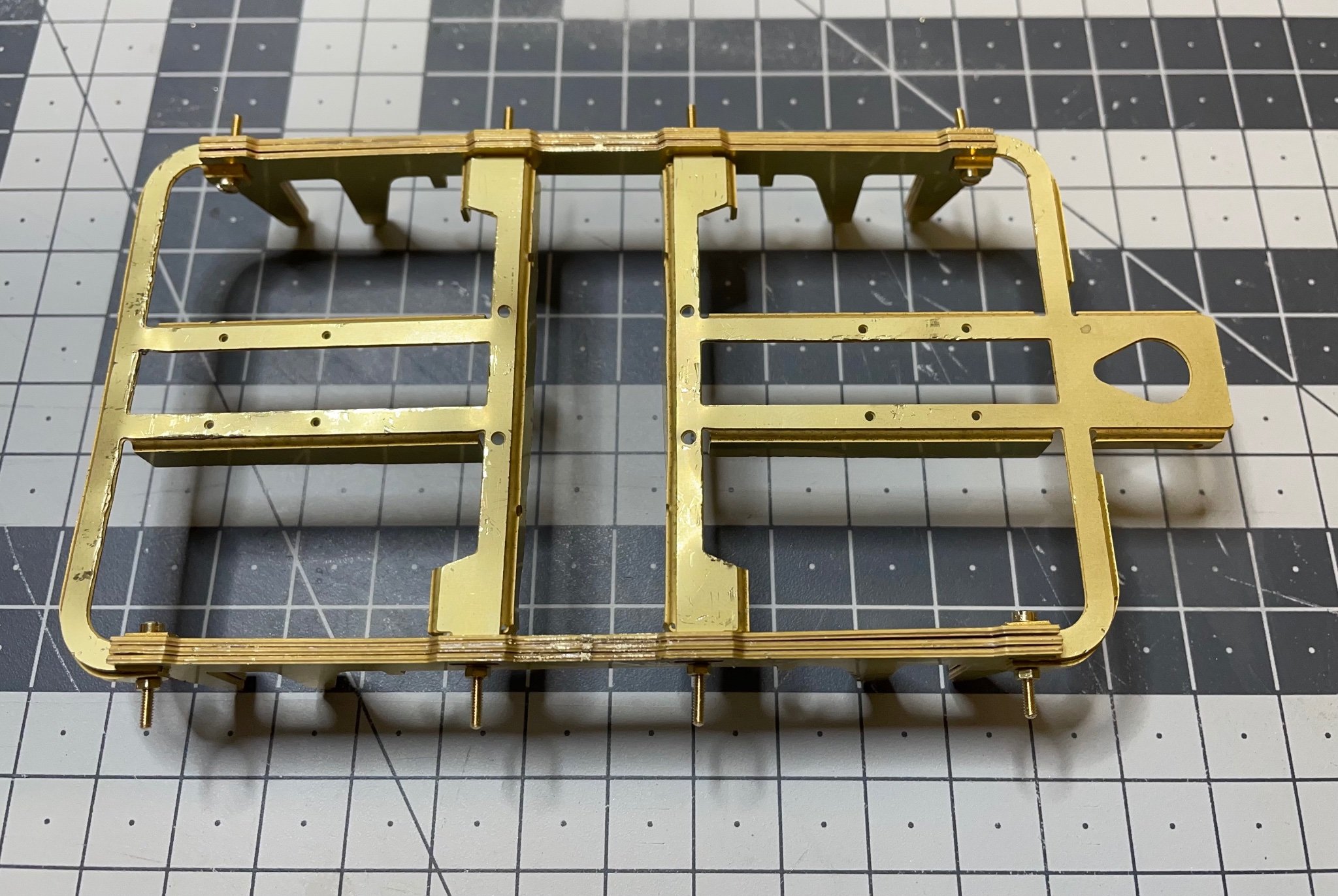
Today I started to build the bogies.
This was a 6,5 hours of blood, sweat and tears.
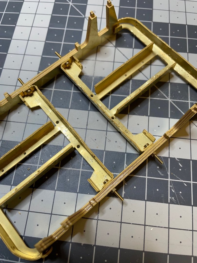
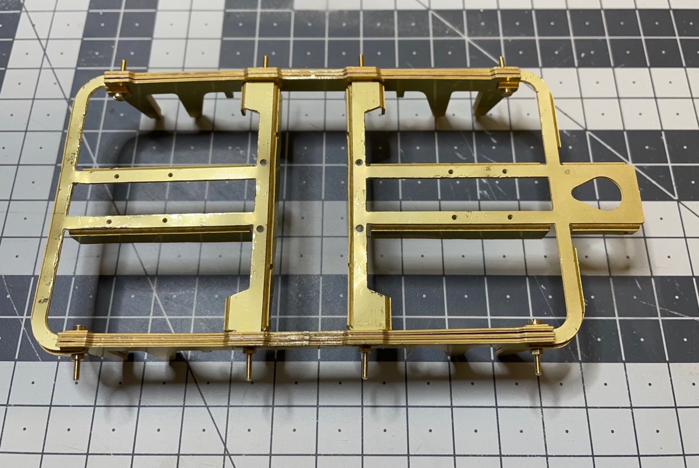
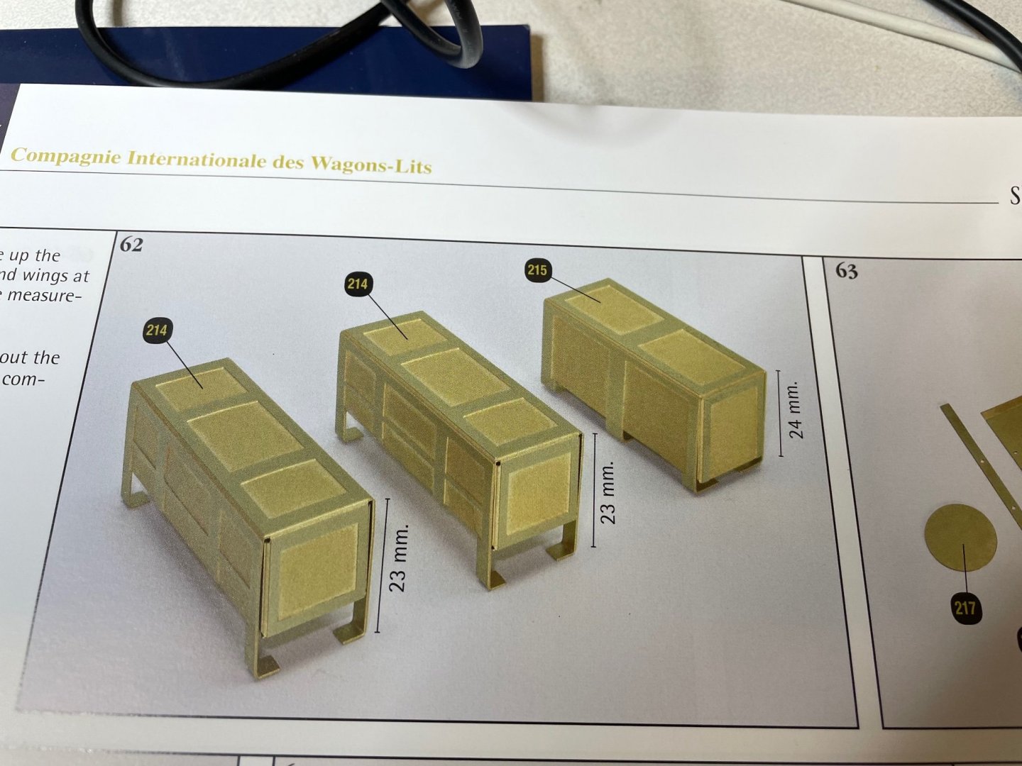
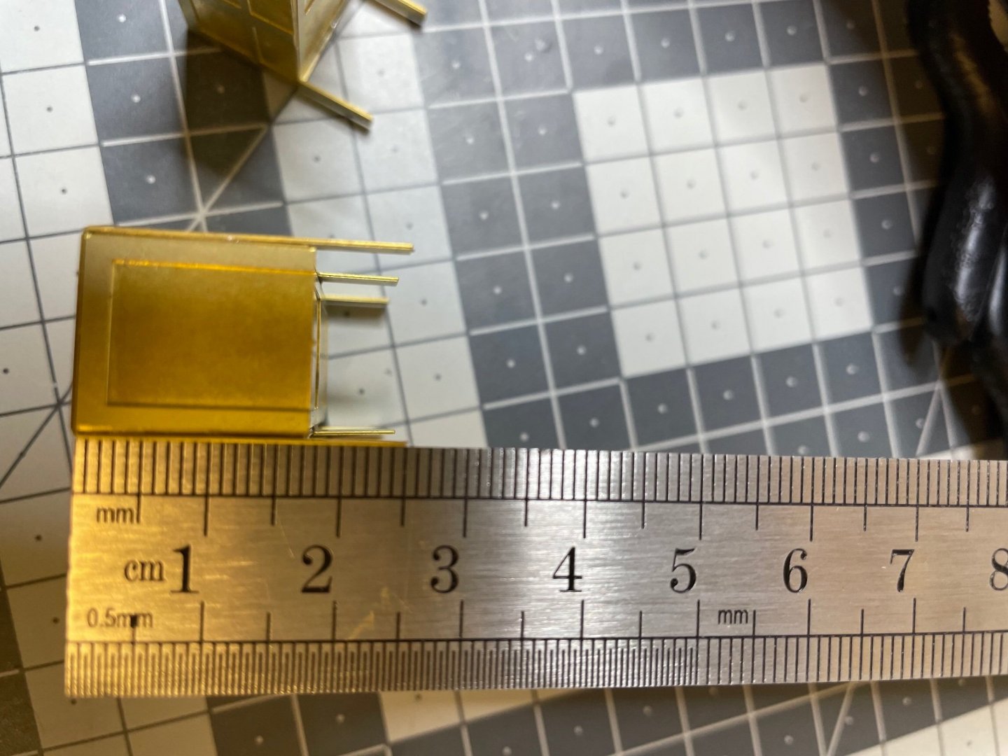
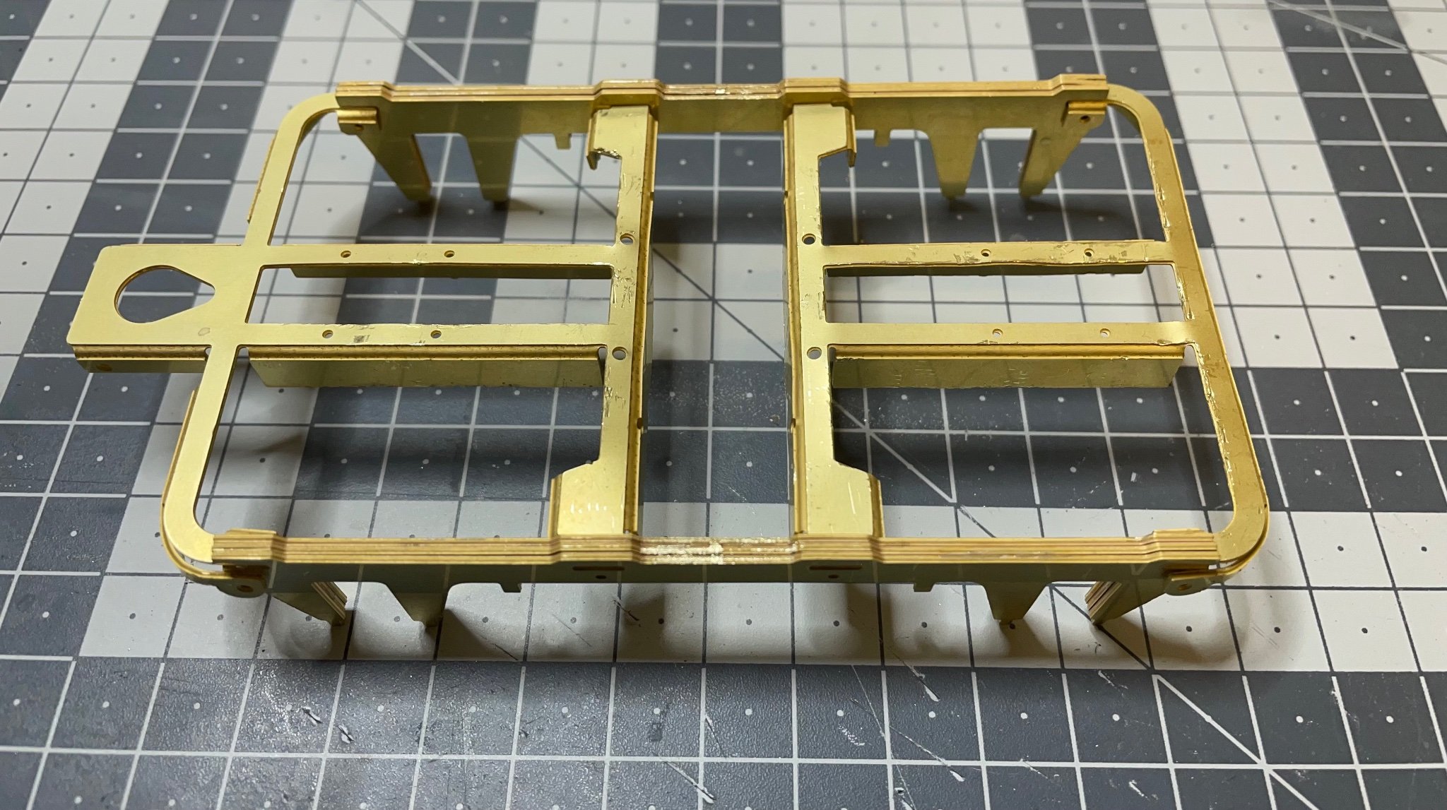
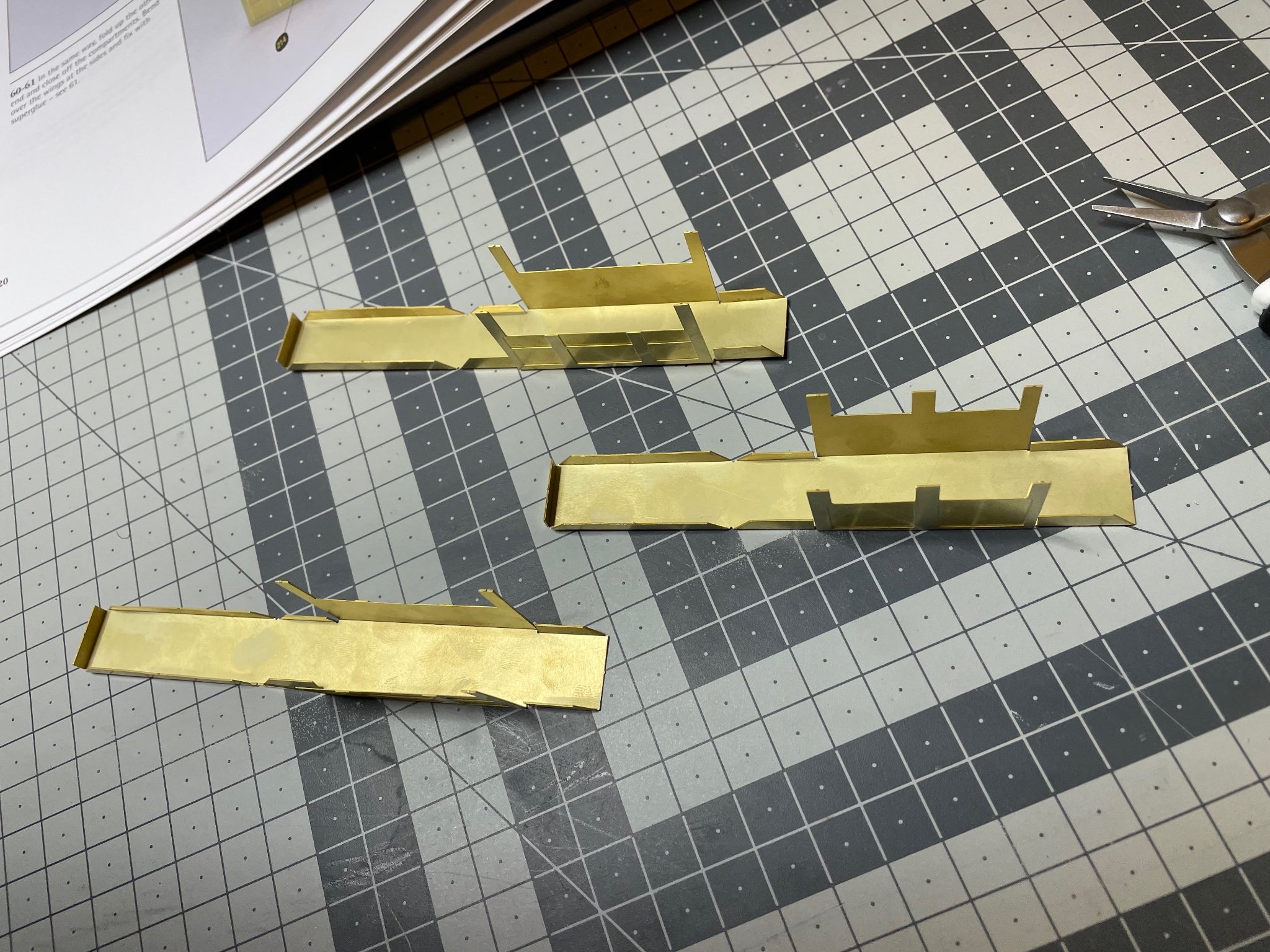
The components come in quite thick brass sheet. I have to say that the build videos of this kit I saw on the internet about bending these parts, are like a joke. At least at my level of experience, there is no way bending them easily using just a pair of pliers and hand. I am talking about bending the long sections on the sides and "wings" in the center. Since the section you want to keep flat is much narrower than the section you want to bend, the flat part bends before the section which you actually want to bend. Then a lot of twisting, unbending, hammering...
I used double pliers, hammer, thin pliers, briefly everything at hand while trying not to damage the visible side. Well, after all, I am quite happy with the result, for a first time handler of brass sheet at this scale.
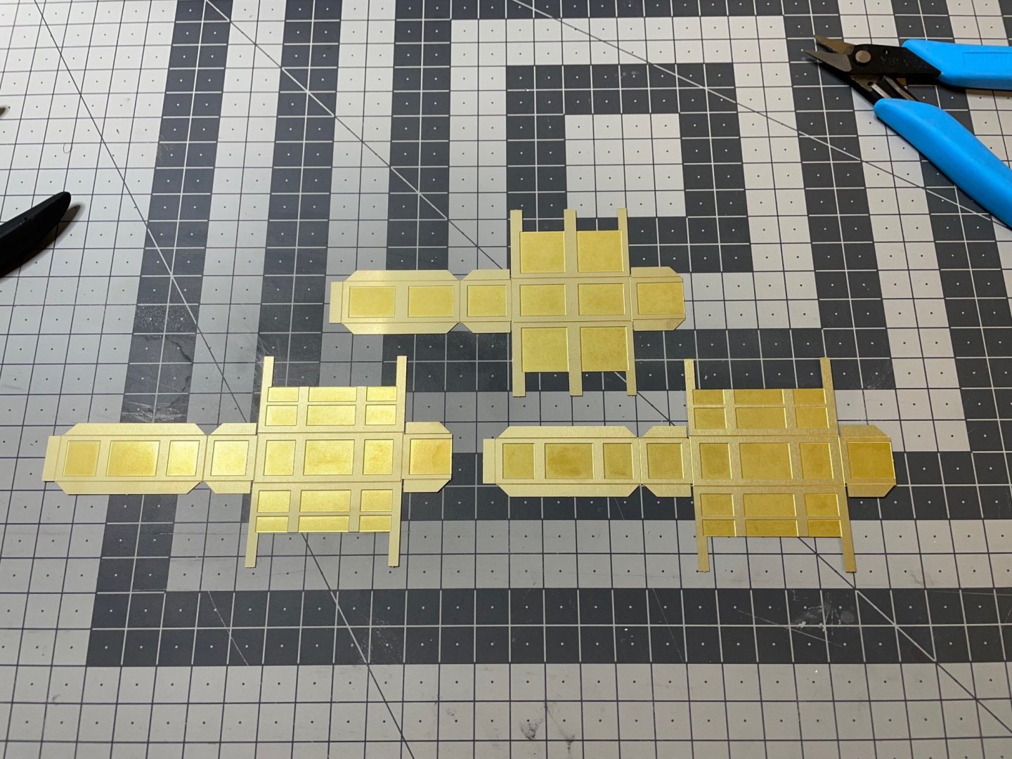
Figure 62: This is how we start.
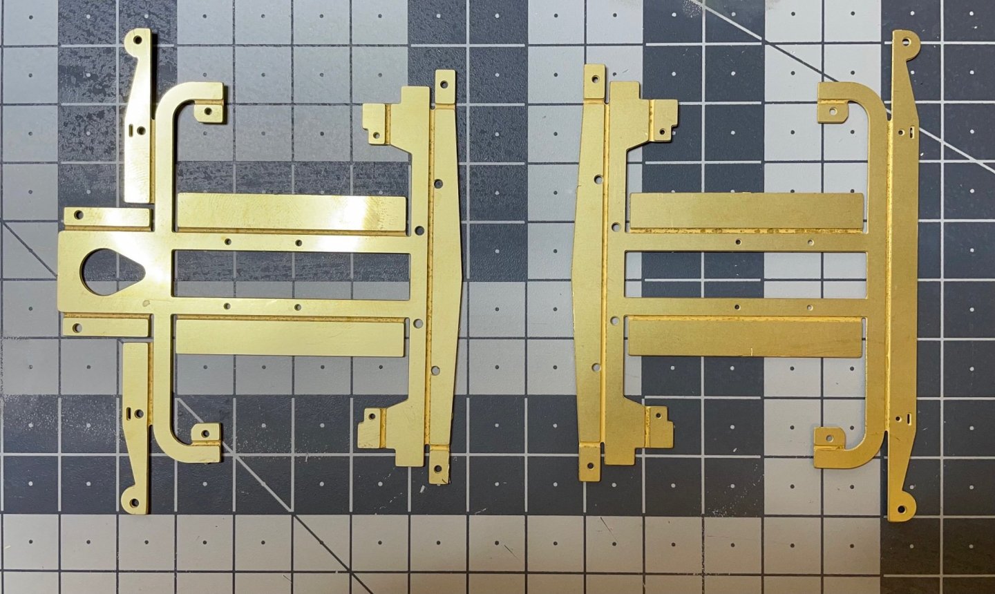
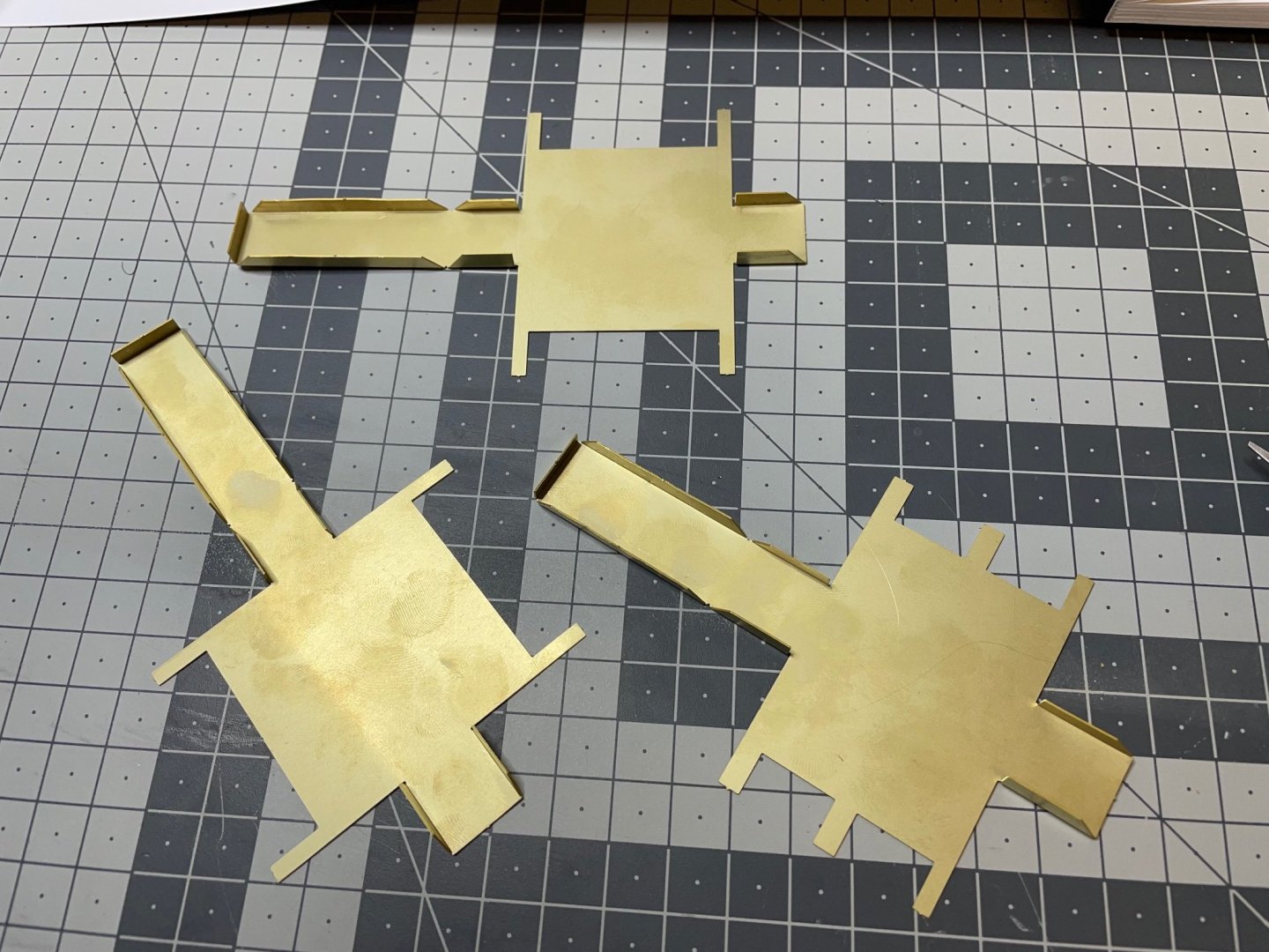
Figure 63: The hardest areas are bent. Never mind the small distortions. I will straighten them on the way as good as I can. Most scratches will stay under the paint and on the invisible side once they have been installed under the chassis.
-
-
BUILD DAY 4: 2 hrs (TOTAL: 11 hrs)
Completed the railway as described in the manual. Like I wrote above, I don't know what to do with it yet. If I choose to include it in the display then I may add some pebbles etc as decoration. So far I put it aside.
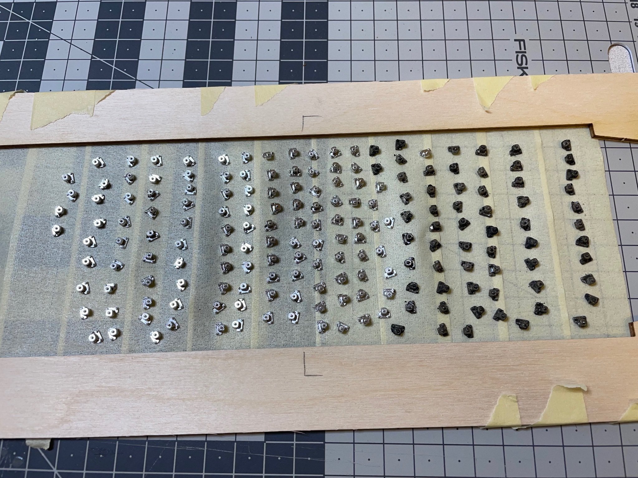
Figure 58: Fixings for the rails placed on the sticky side of masking tape, invisible sides down, ready for spray paint. I tried staining some of them with the brass blackener but it didn't work well. That's why they look dark. Probably because these are pressure die-cast, not brass. There are 180 of them.

Figure 59: Sprayed from a can of black primer. They look good enough and just the matt tone I wanted therefore I am not going to put any additional paint on top of them.
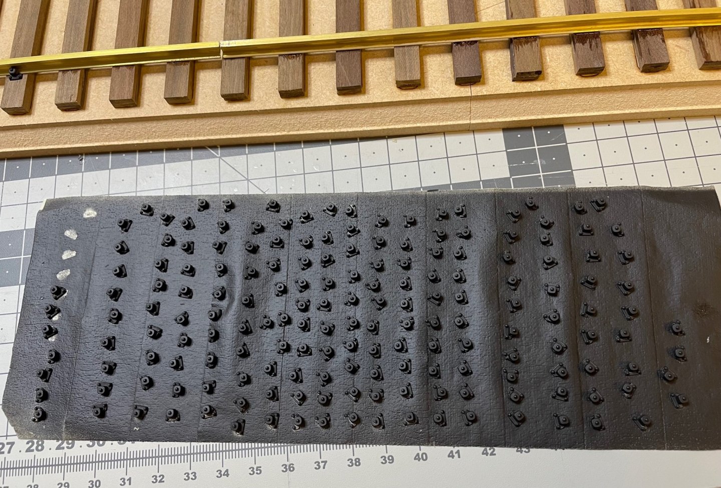
Figure 60: I work in batches of around 10. I first place them dry on their spots, then apply a tiny amount of ultra-thin superglue with a thin nozzle from the rail side. It penetrates instantly between the part and the rail and bonds right away. Saves a lot of time compared to gluing and placing each piece one by one.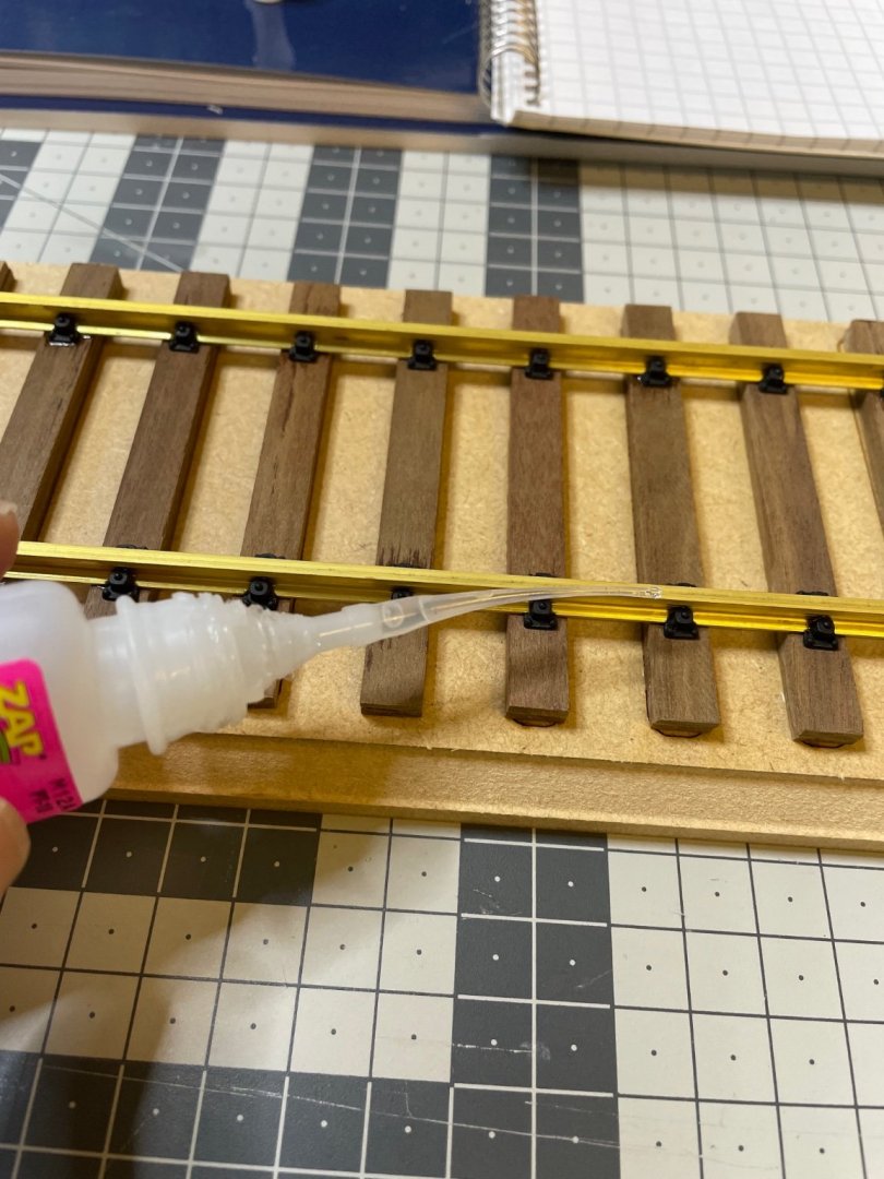
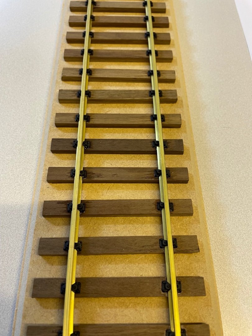
Figure 61: Railway ready.
That's all for today!
Thanks for watching! -
17 hours ago, yvesvidal said:
I know that you have spent some time working on the track, and I would like to suggest another solution, more realistic in my opinion.
Since you live in Europe, you have easy access to Marklin 1:32nd scale tracks. I recently used multiple flexible pieces to build a display for my BigBoy:
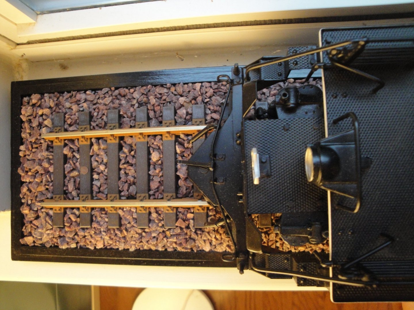
The track is raised on two pieces of wood to create the crown typical of railroad tracks. The plates are then painted in Rail Brown (Rusty) and the ballast is made of chicken grits #2, glued with diluted white glue. The gluing is the most delicate task since you do not want to put any glue on the sleepers or on the rail itself. The dilution is done with water and alcohol. Chicken grits is a small granite pebbles given to the hens so they can grind their food. You should be able to find that in any farm supplies store. Gluing is done with an eye dropper and a lot of patience.
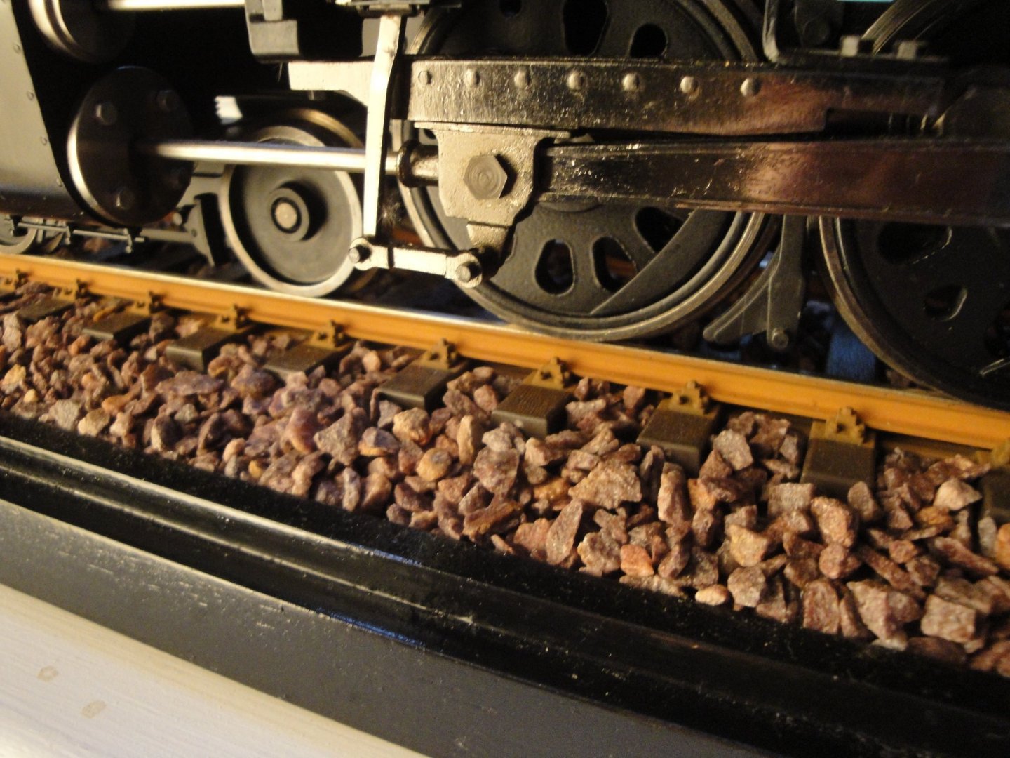
The Marklin track is very European and will in my humble opinion be more realistic than whatever Amati has provided in the kit.
Yves
Thanks, Yves, If I go for the railroad diorama option, I will consider this. Right now I am building the railroad only for curiosity and for reference to the distance between the wheels.
-
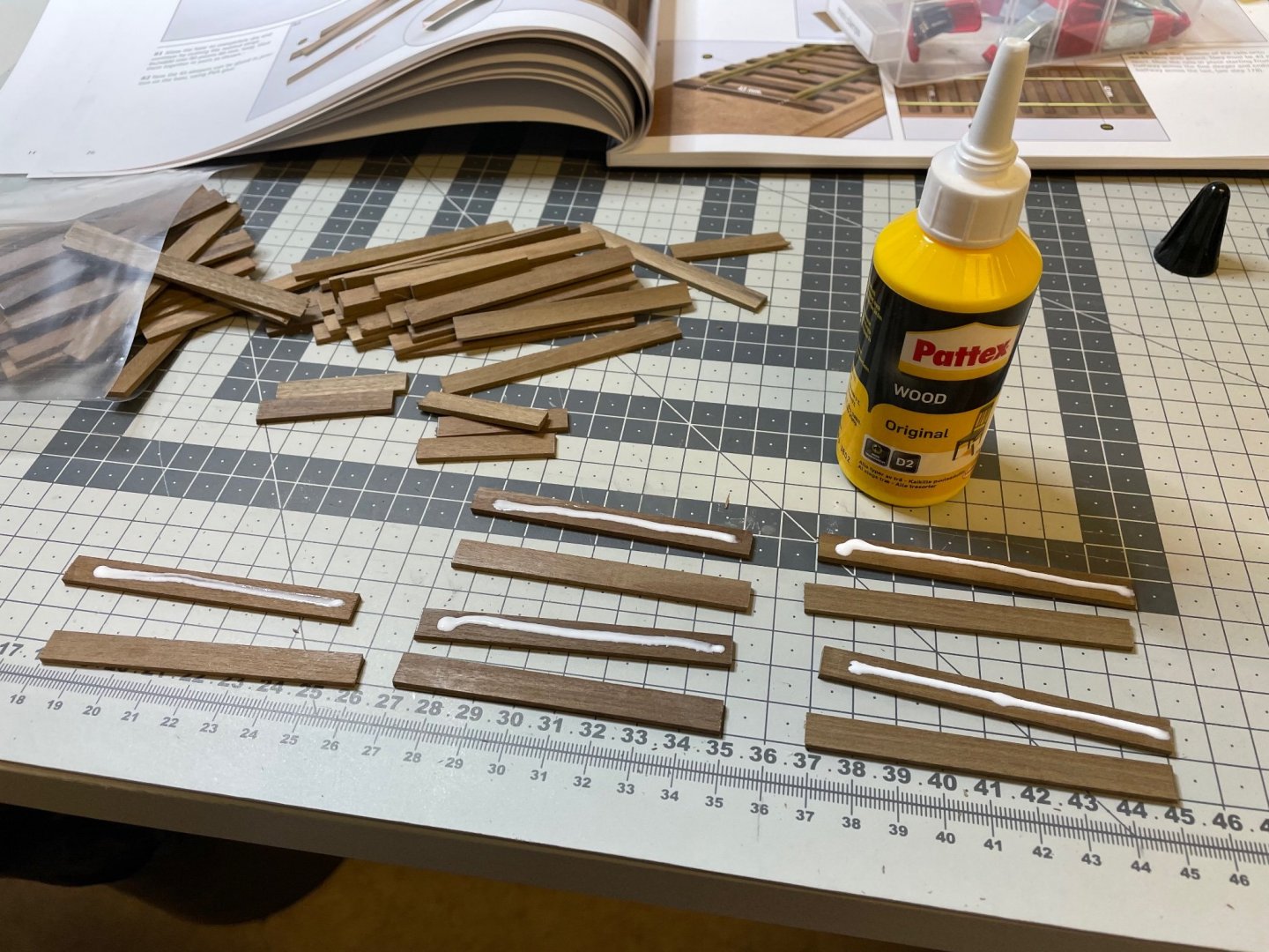
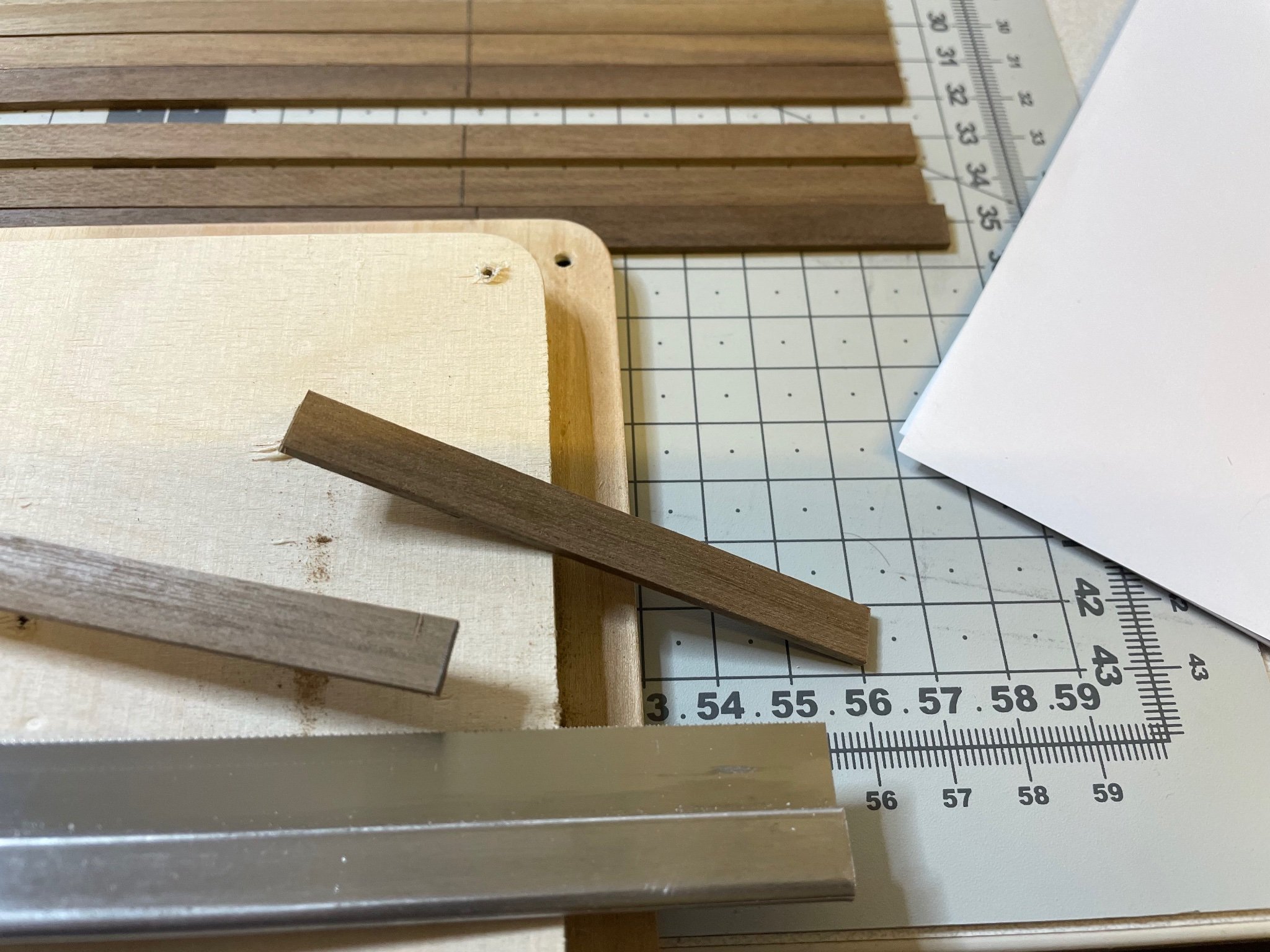
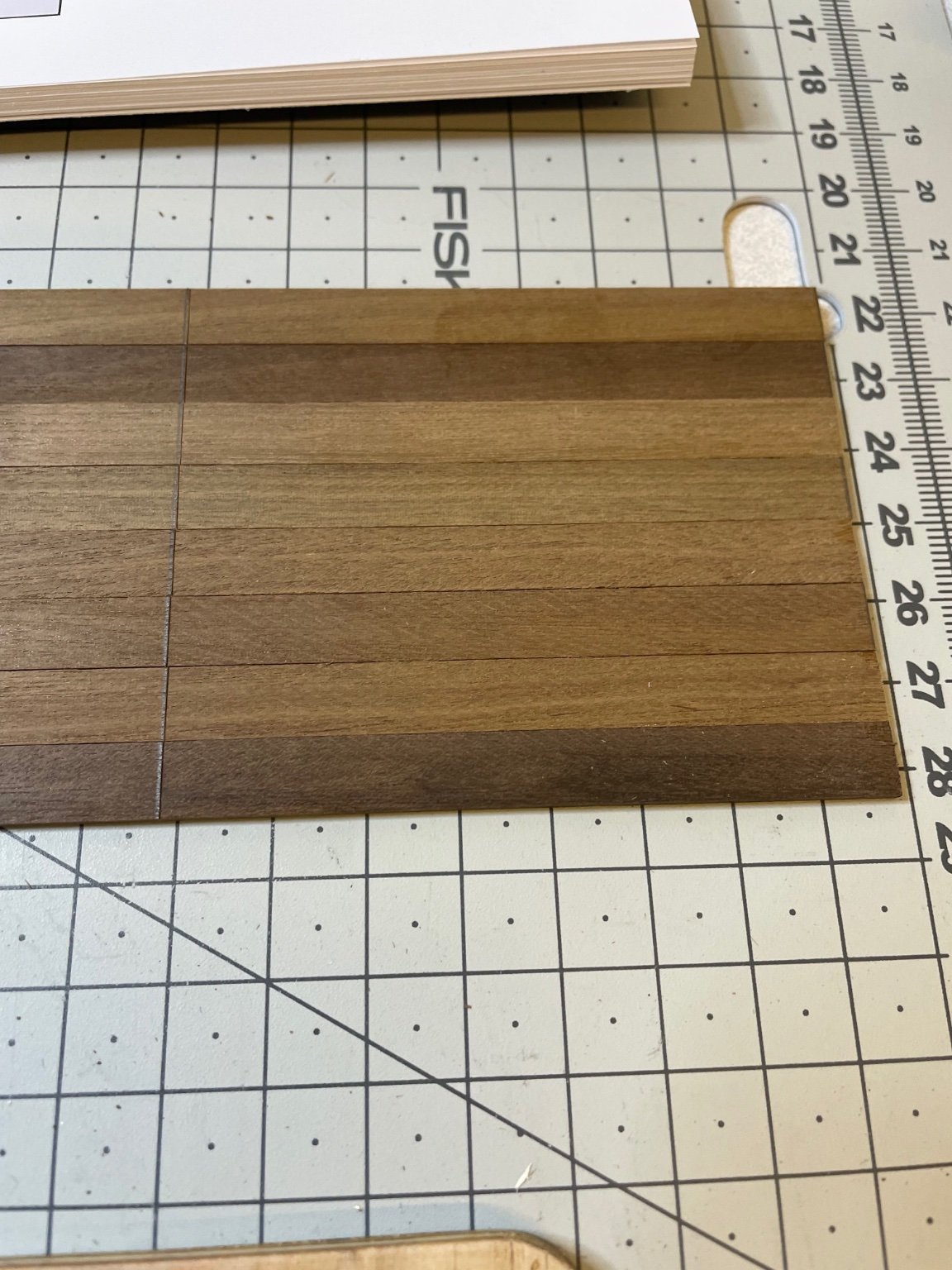
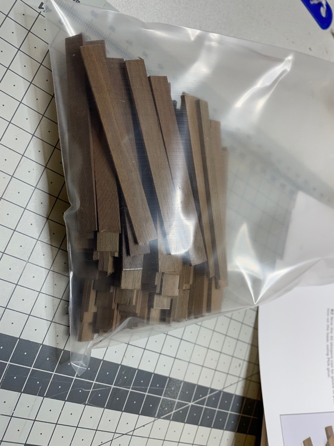
Sleepers
You need to cut 80mm size from the 8x2mm walnut strips supplied.
Altogether 90 pieces. In the photo that's 1 down,") only 89 to go
only 89 to go
Figure 52:
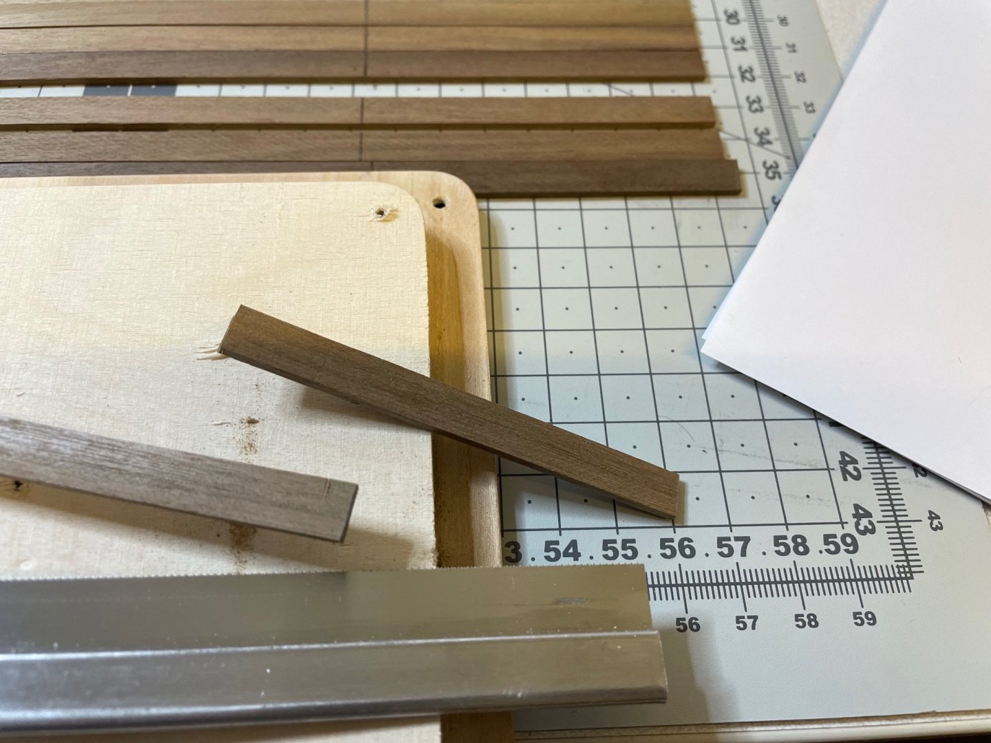
I used saw to cut them.
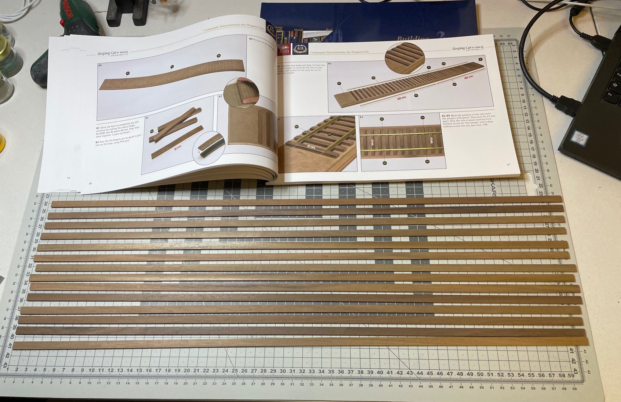
Figure 53-55:
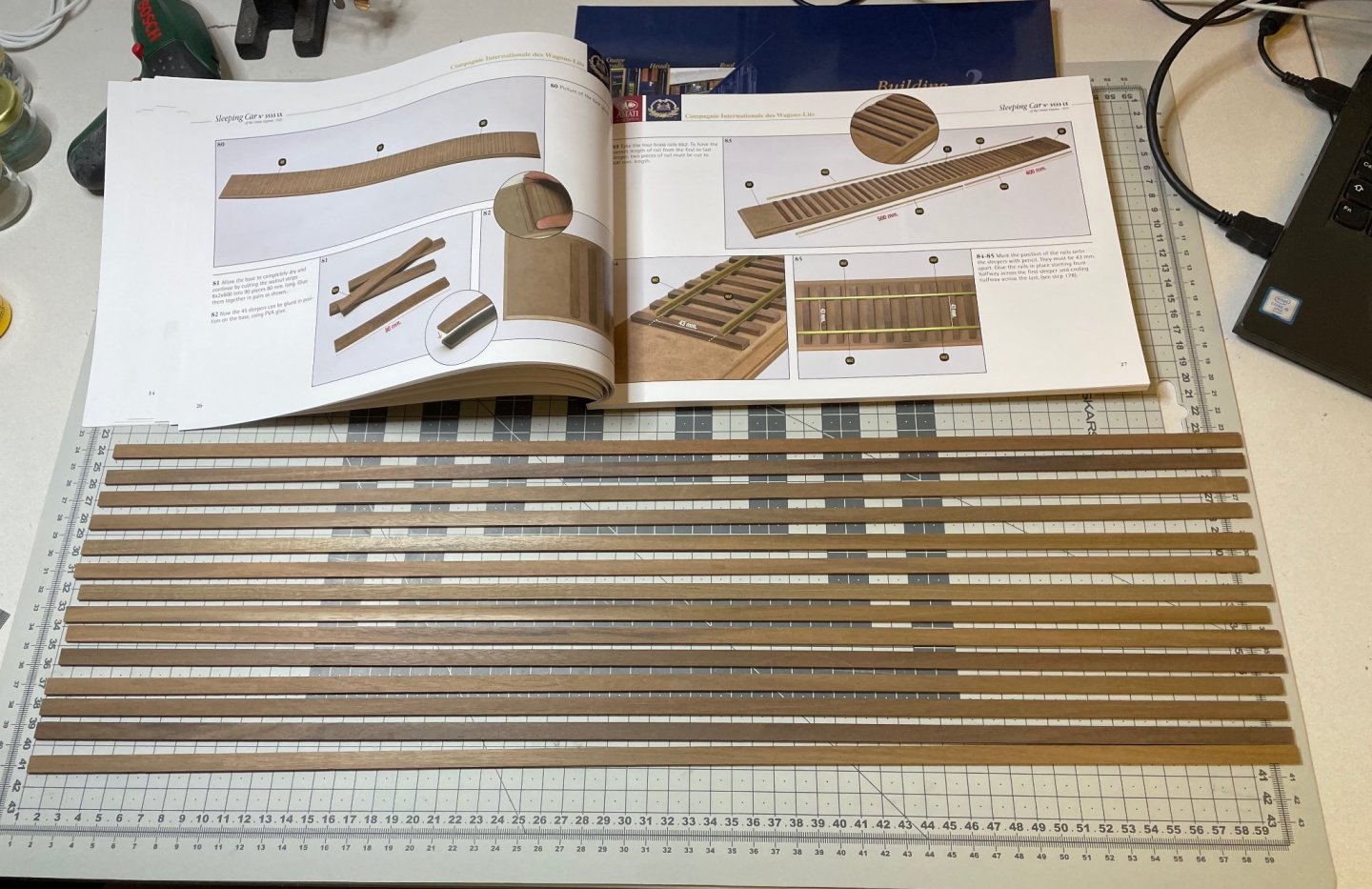


Each two are then are glued in pair to end up with 45 sleepers.Figure 56:

That's all for today!
Thanks for watching! -
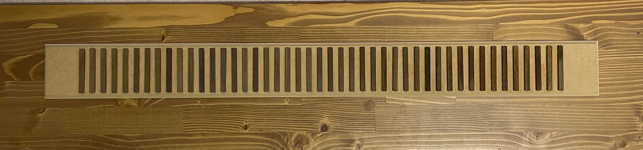
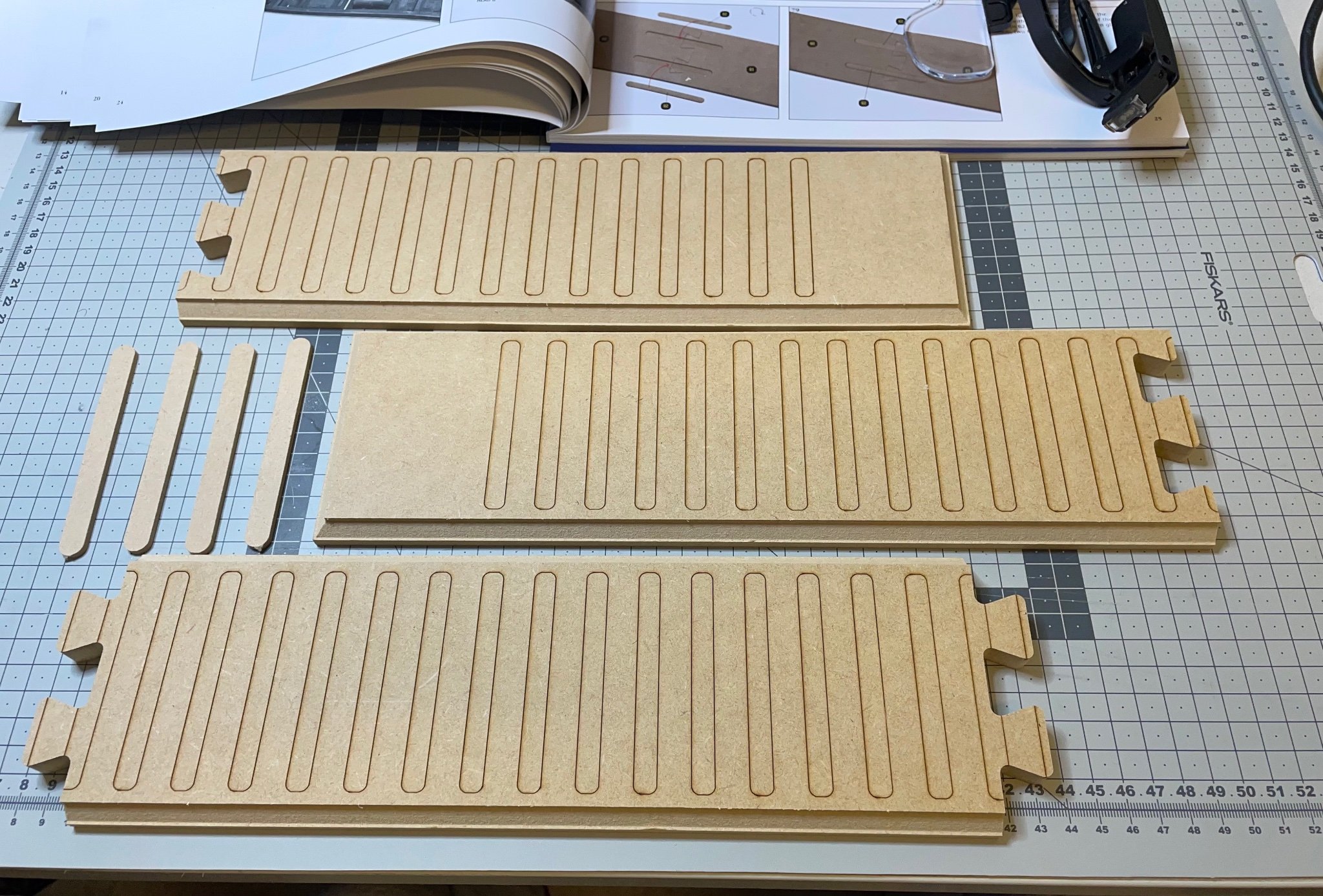
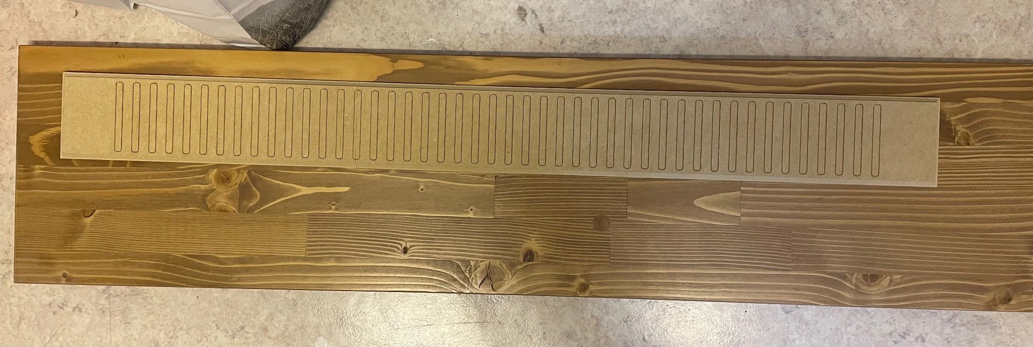
Rails.
Well I am not a big fan of dioramas. I don't like adding even human figures, I just prefer to display the model just as it is. It is a question of taste.
Having said that I will give a shot to build the rails. The main reason being the instructions say they will be used to align the wheels later. I am not sure if I would put it to the final display. It is 1 meter long, adding almost 25cms to the length of the wagon.
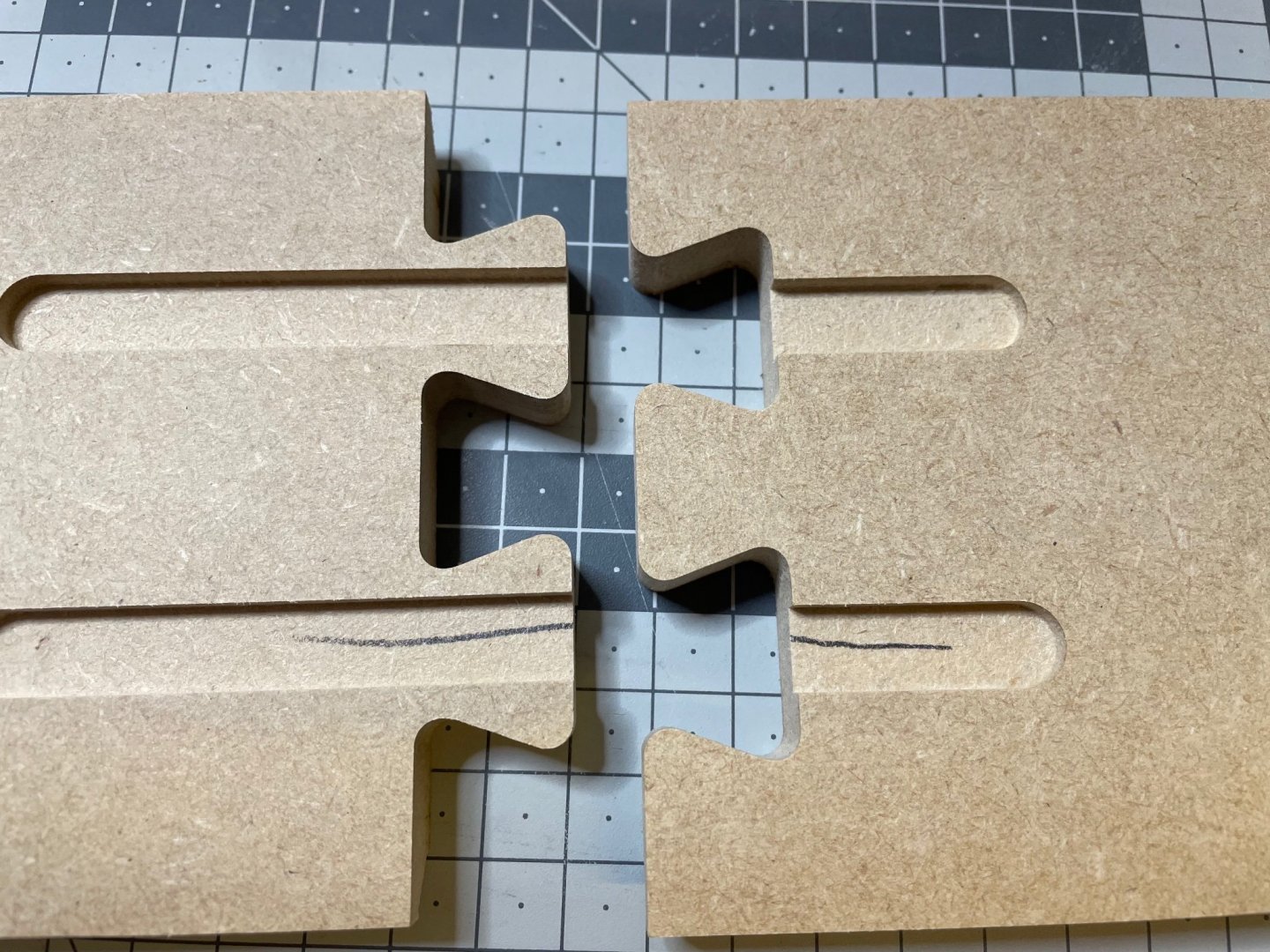
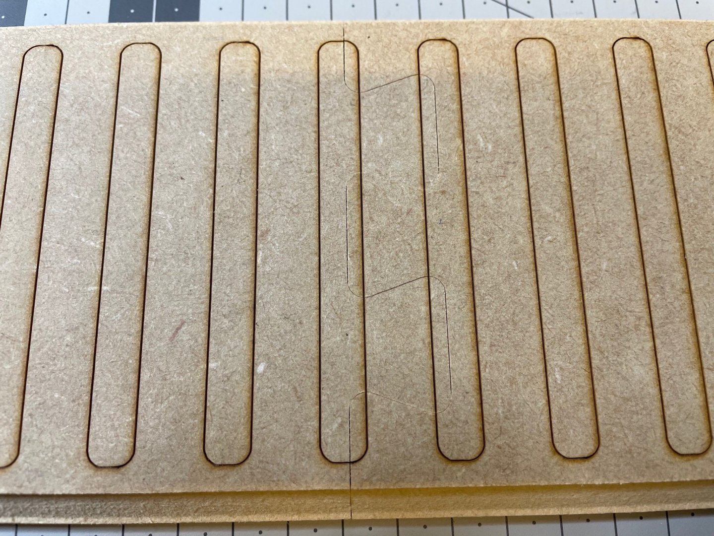
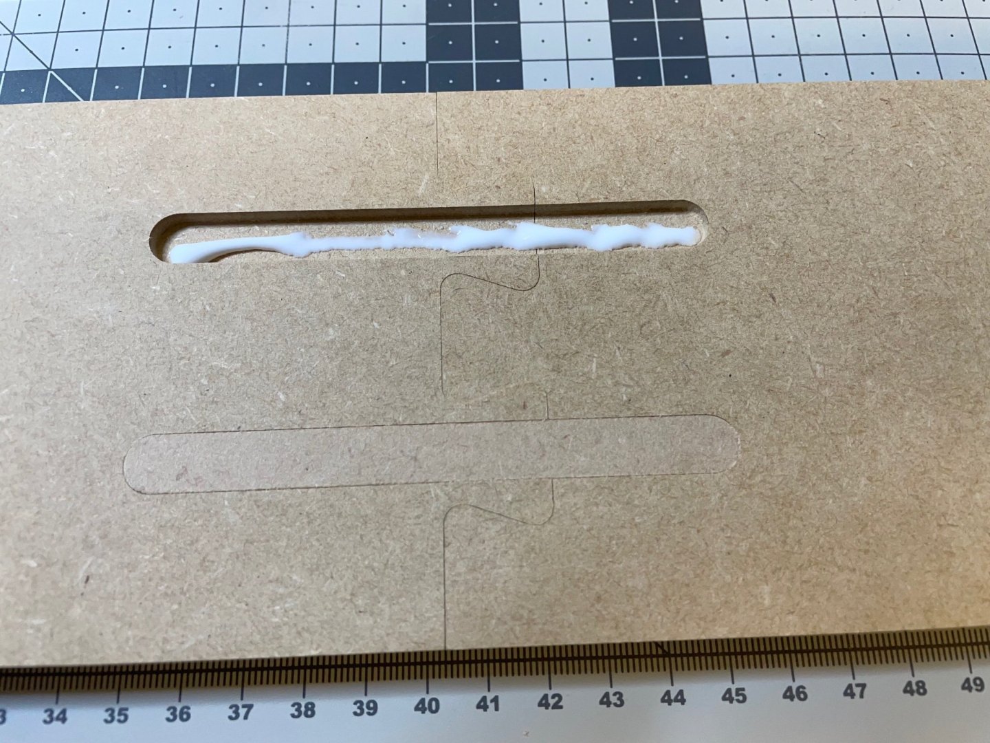
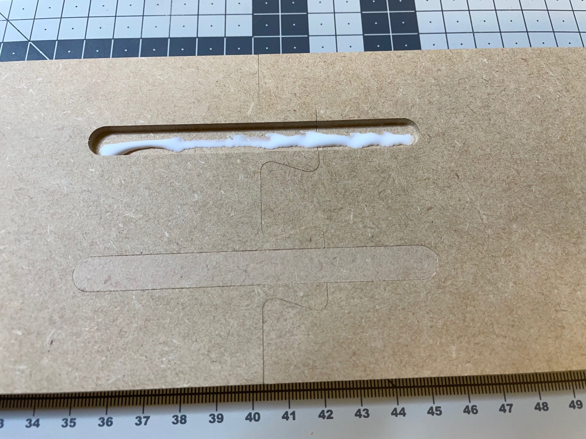
MDF base plates fit extremely precisely.
The pencil mark on the back in two of the grooves tell matching parts.Figures 48-52


-
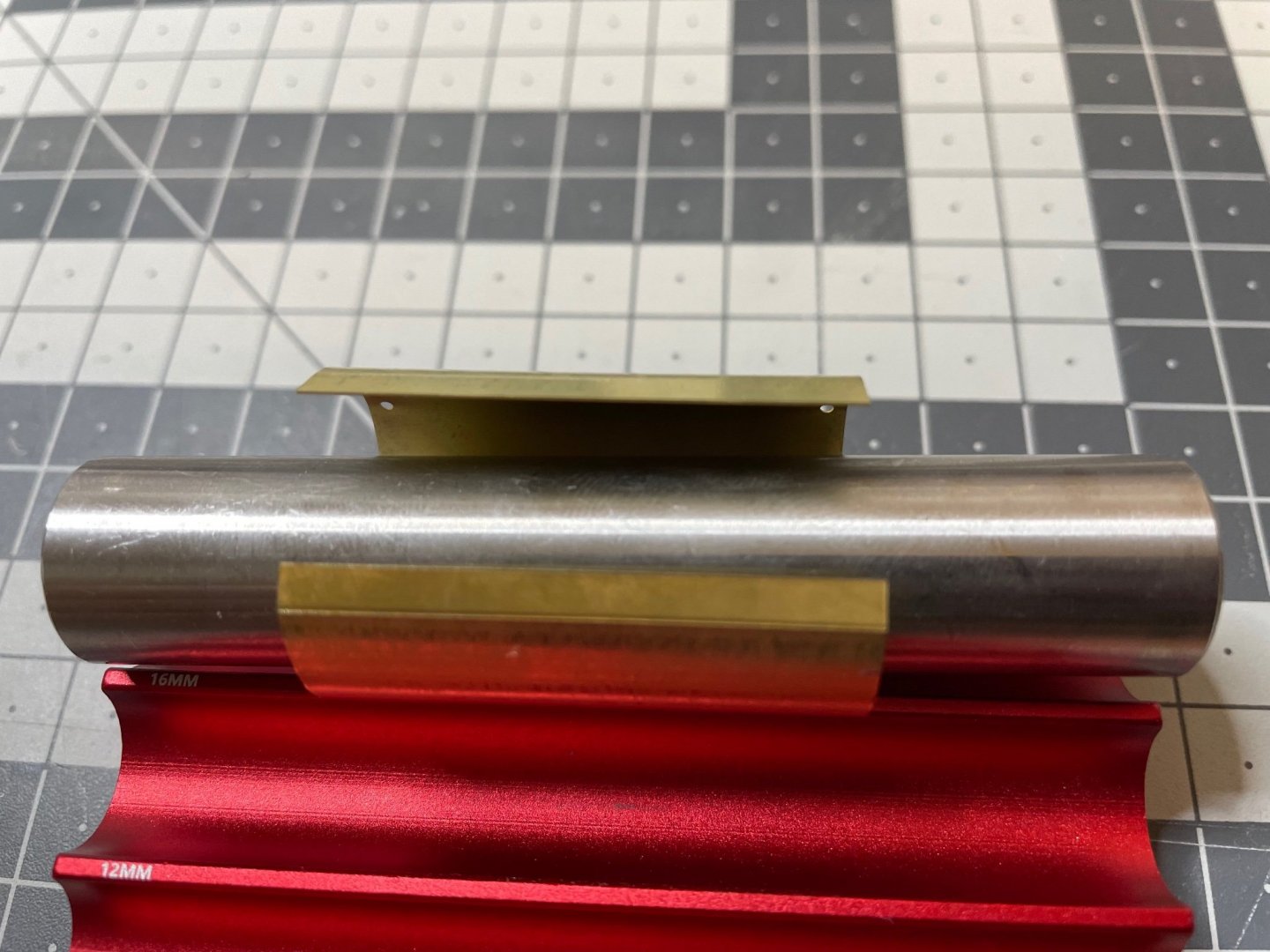
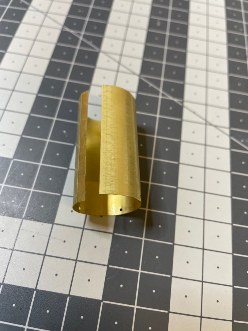
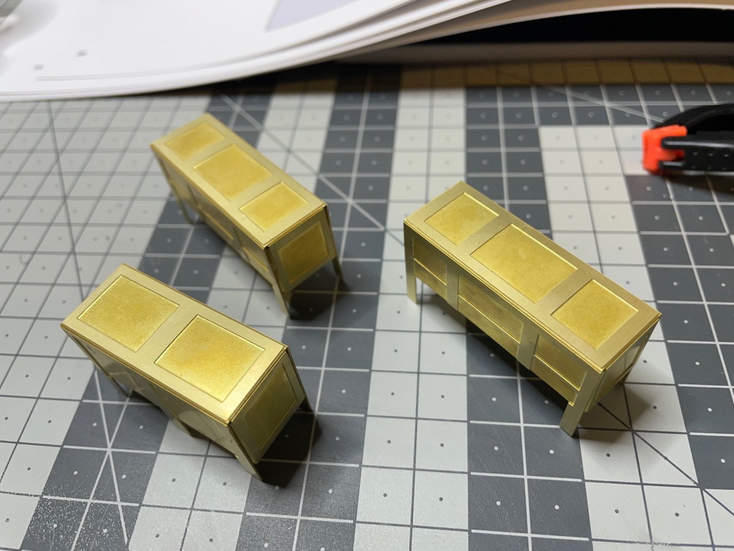
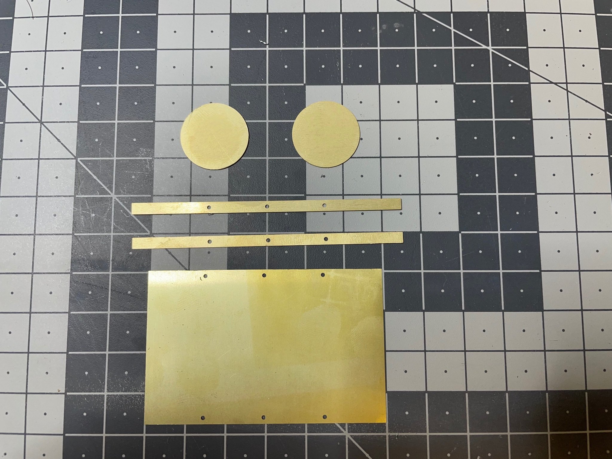
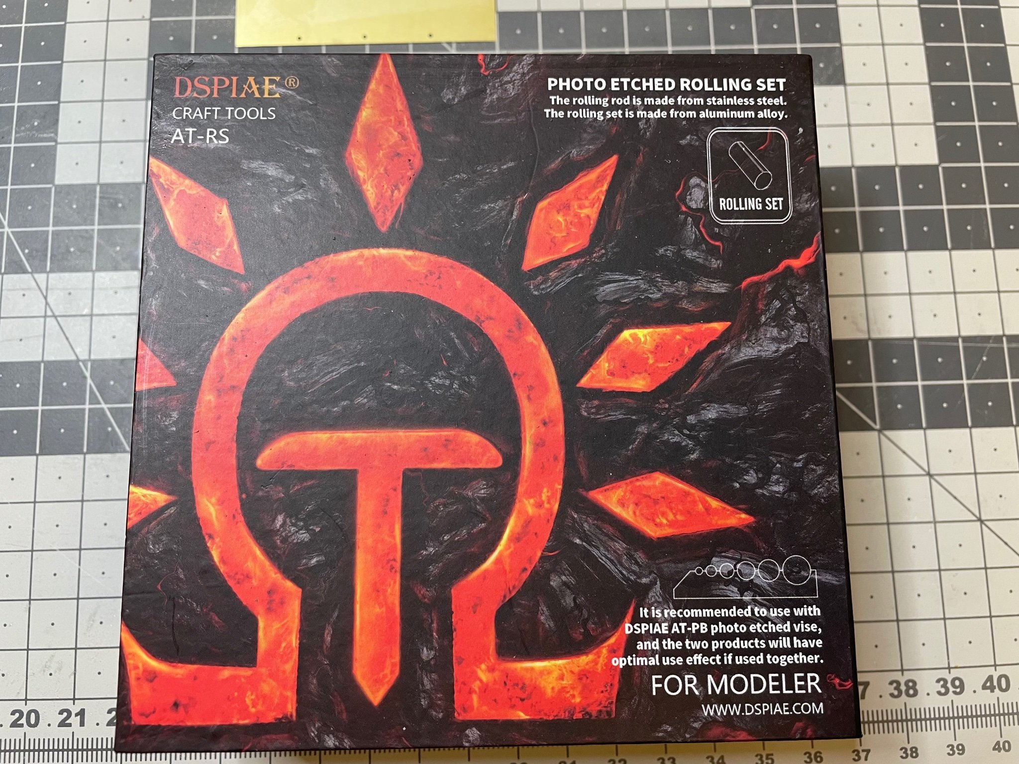
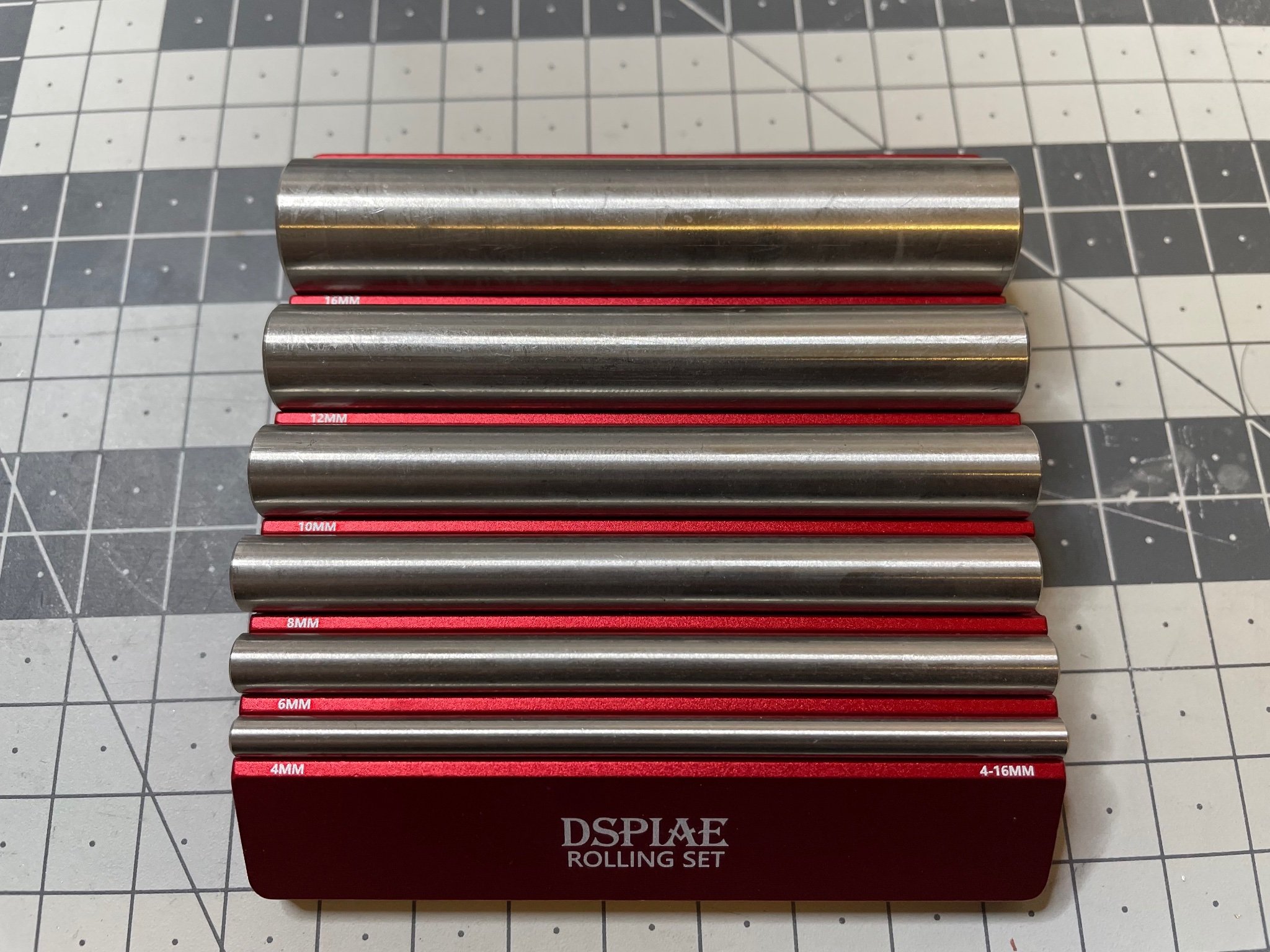
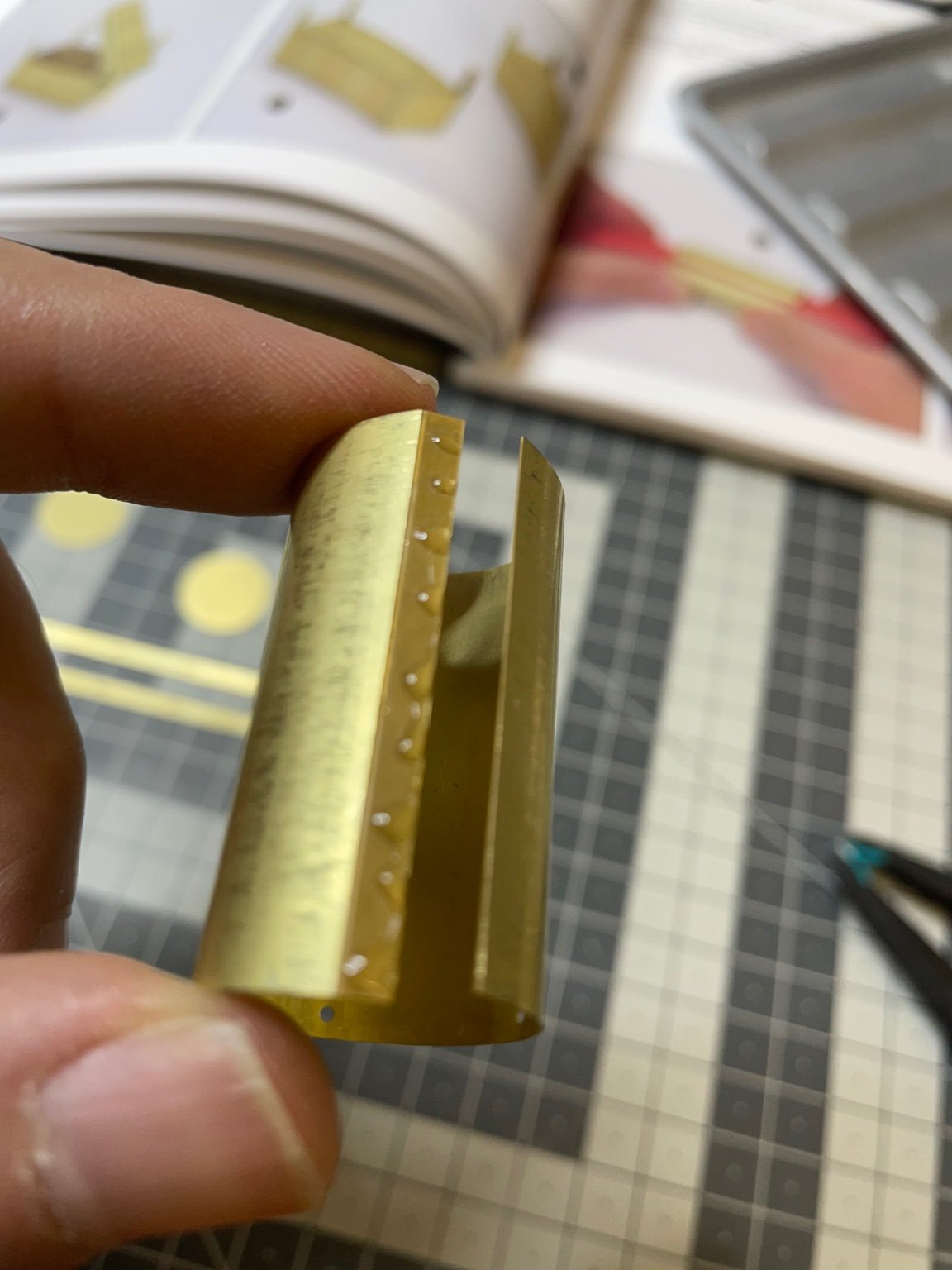
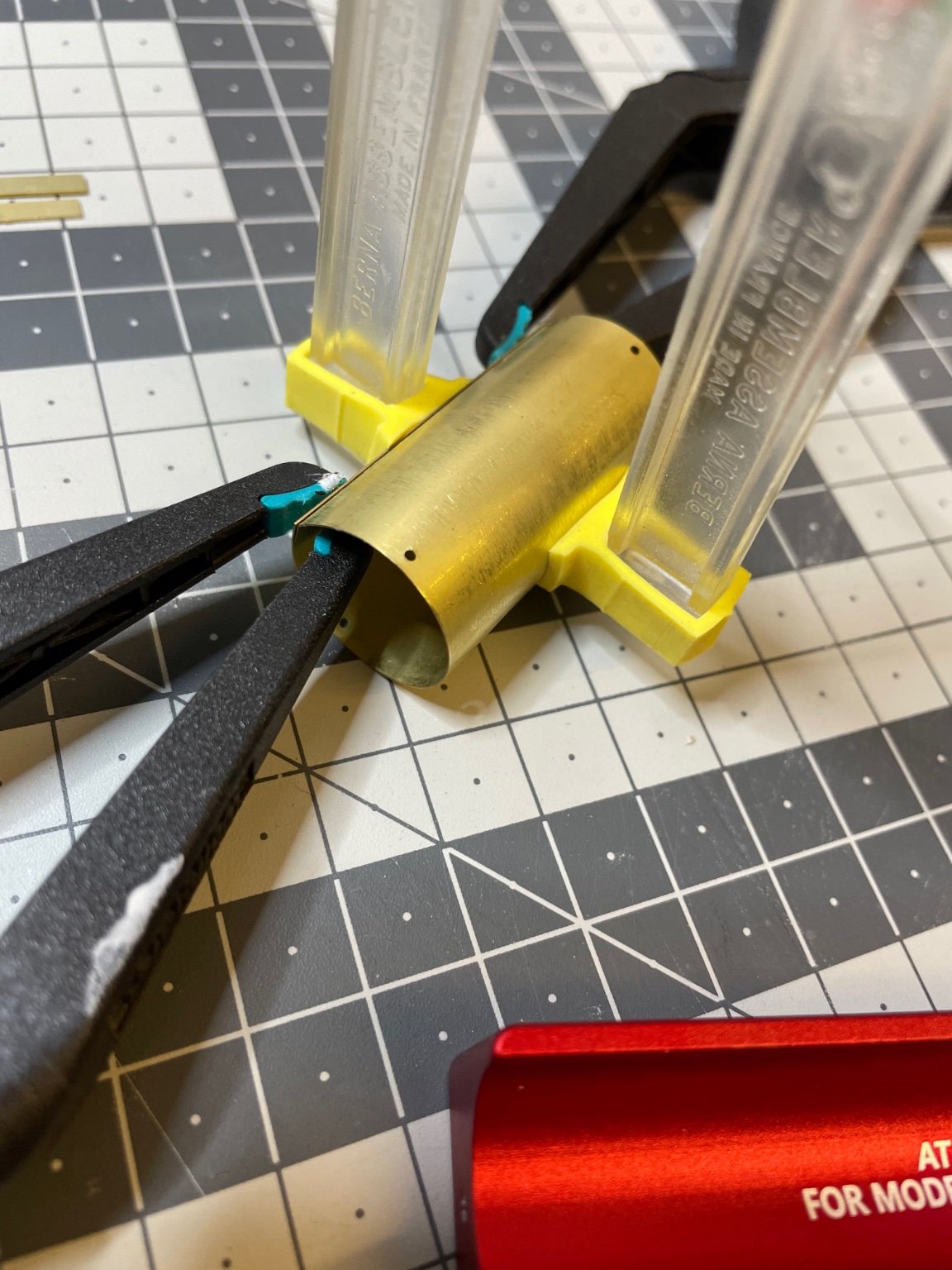
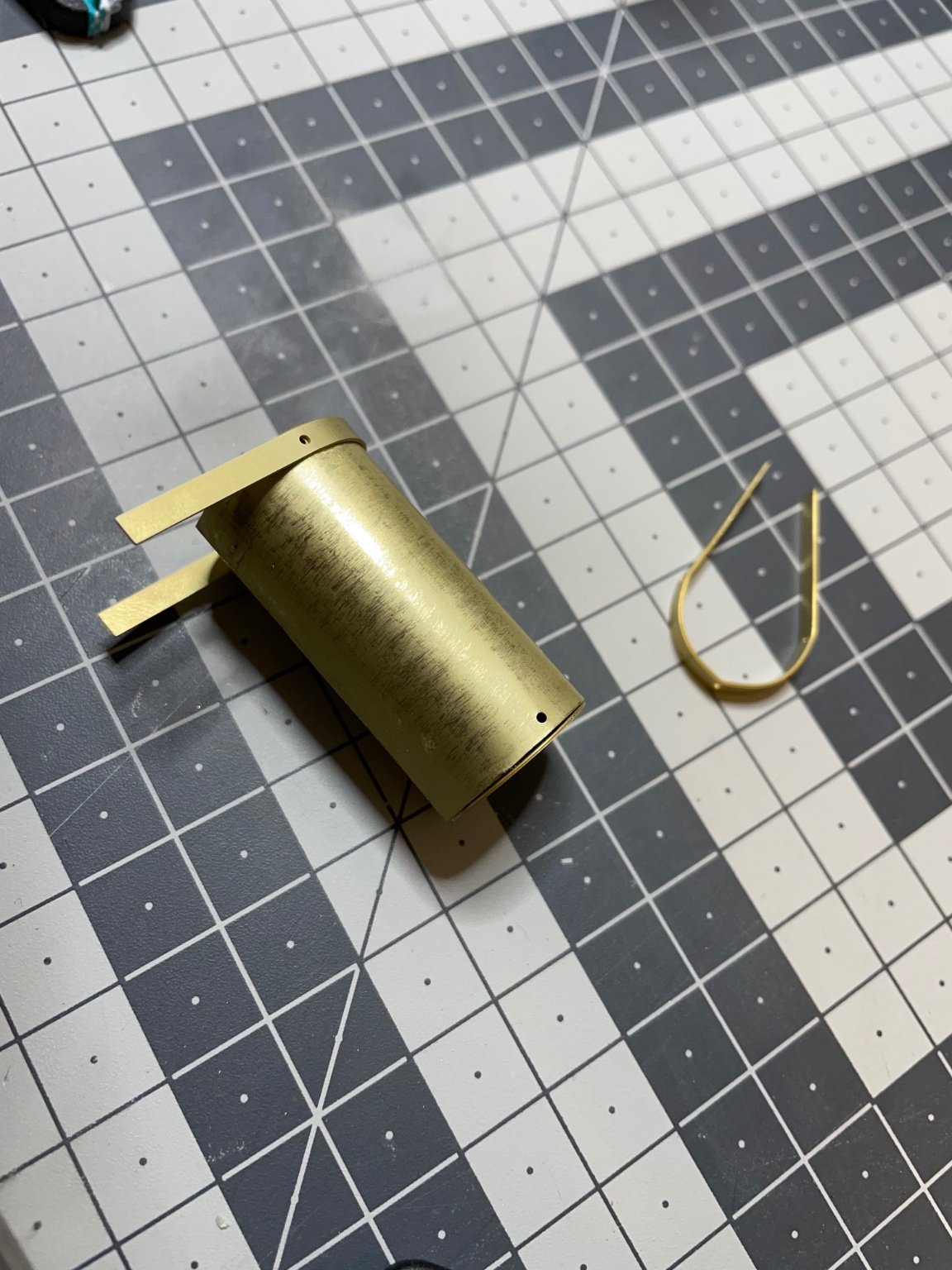
Compressed air cylinder.
First time in my life I have ever bended a brass sheet into a curve.
With the help of DSPIAE brass bender kit, I can say that the result was quite good.
You will make a cylinder of diameter 18mm. I used 16, 12 and 10mm rollers to achieve it.
I had to enlarge the holes with drillbit to fit the copper rivets.Here are 13 photos showing the progess.
Figures 35-47:


- Egilman, thibaultron, marktiedens and 11 others
-
13
-
 1
1
-
This is what I saw complaints in several build logs:The legs are quite short. As opposed to the picture in the manual, you are left with only around 1 mm margin to bend to act as feet to glue on the body.
The photo etched parts are clearly different size than in the manual. A bad point for a kit of this level.
Figures 33-34:
Maybe I'll add some wooden support or something like that to the bottom. I'll see when I come to that.
- thibaultron, mtaylor, Javlin and 7 others
-
10
-
BUILD DAY 3: 3 hrs (TOTAL: 9 hrs)
Making the battery housings. I used superglue all the way. Some modelers use solder at certain spots. Though I have soldering kit and done soldering on electronics level, I am not thinking of using it in this build, unless I have to.
Figures 28-32:


-
-
18 hours ago, yvesvidal said:
Great topic and beautiful kit. I hope you will give us a complete assembly review and not stop like James H did, with the kit that Amati sent him for review.
I collect trains at the scale of 1/48 and 1/32nd and thus have a special interest for that Build.
In addition, this kit depicts what used to be the most luxurious and romantic train in Europe. The Orient Express no longer runs between Paris and Istambul, Turkey unfortunately. I met an old colleague from IBM in the late 80's who used to be a sales representative for IBM. He and his wife as well as the entire French Sales team were taken by the Sales department of IBM for a trip between Paris and Venice in the Orient Express. The entire train was rented by IBM. He told me that nothing in his life had been more luxurious and lavish than this trip.
Yves
Thanks Yves, I also hope to post all my work to completion!
I would also dream of traveling in Orient Express, maybe some day some company will bring it back as a tourist attraction, who knows.
- Old Collingwood, Jack12477, Egilman and 5 others
-
8


Orient Express Sleeping Car 1929 by aydingocer - FINISHED - Amati - Scale 1:32
in Non-ship/categorised builds
Posted
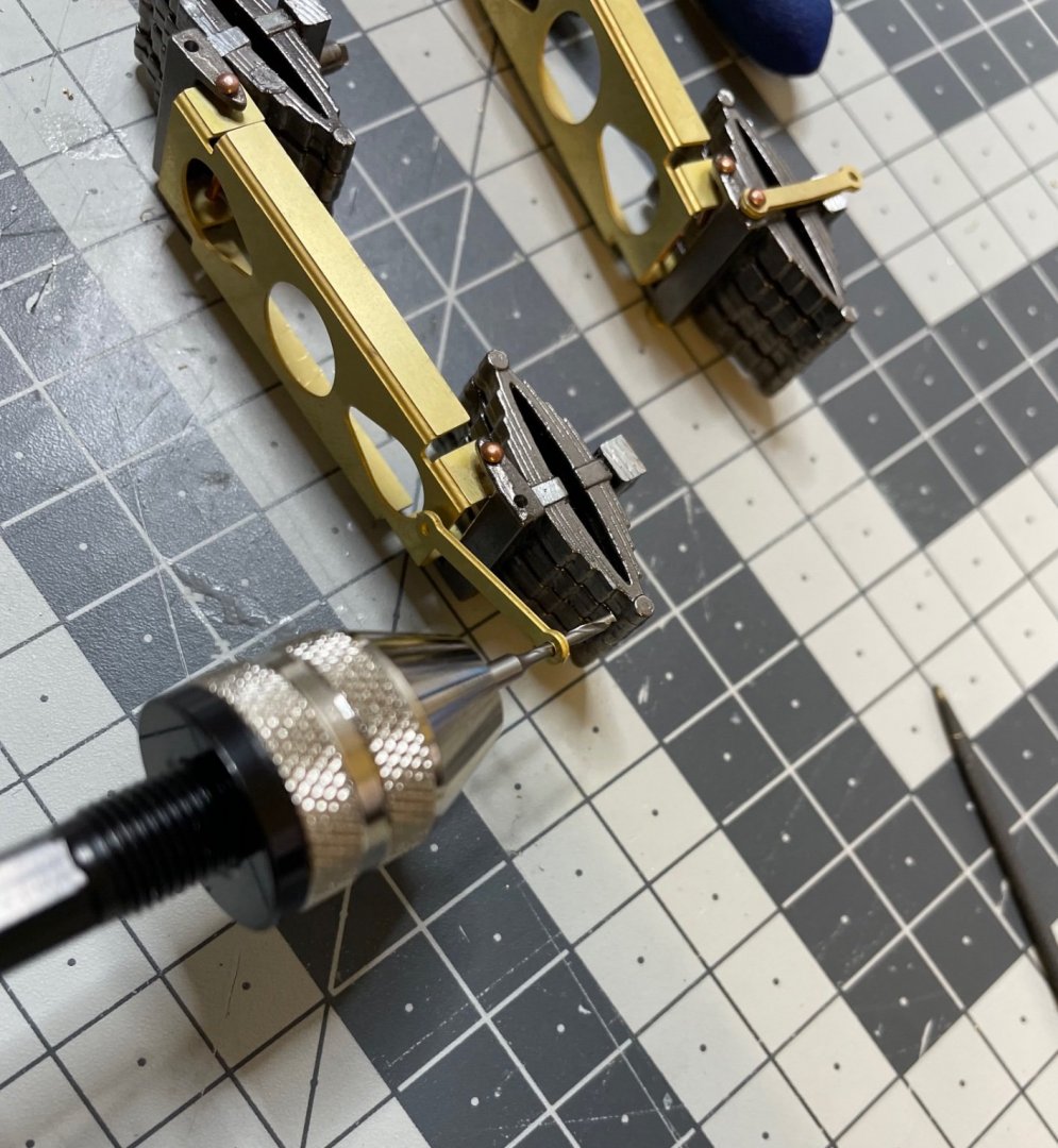
Time to install the wheels.
Figure 103: Parts.
Figures 104-105: Painted matt black with airbrush.