
Supplies of the Ship Modeler's Handbook are running out. Get your copy NOW before they are gone! Click on photo to order.
×
Chuck
-
Posts
9,447 -
Joined
-
Last visited
Reputation Activity
-

 Chuck reacted to Stuntflyer in HM Cutter Cheerful 1806 by Stuntflyer (Mike) - FINISHED - 1:48 scale
Thank you all for the kind words, comments and "Likes".
After a week off vacationing, I'm finally getting around to building again. I finished the lower backstay and tackle today. Next up is the sling and then the mainstay. After that I'm going to clean up some of the scratched paint work. At least that's the plan.
Mike
-
Chuck reacted to Dharma66 in HM Cutter Cheerful 1806 by Stuntflyer (Mike) - FINISHED - 1:48 scale
I read the whole of Chucks Cheerful thread, and thought to myself that no mere mortal could ever replicate that.
You sir, are no mere mortal.
-
 Chuck got a reaction from mtaylor in HMS Pegasus 1776 by Trussben - 1:48 - Swan-class sloop based on TFFM
That is looking great Ben.....Everything seems back on track.
-
Chuck reacted to BANYAN in Michael Mott Designed Third Hand
Hi folks,
I thought I would do a bit of a tool review on a great new tool I have just received. Michael Mott, in his build log for the restoration of the Basset Lowke Albertic introduced a great new third-hand he had designed for himself - a new take on the usual designs. This looked very promising but as I am no tool maker, I asked him if he might make one for me - which he did See following picture.
This was such a great adaption of the common cheap tool that are usually next to impossible to use for finer soldering projects, that I started looking at alternate uses for it. I realised it could also be very useful for rigging and opened another discussion with Michael on alternate clamp designs/arrangements that would not crush rope cordage, but could also be utilised for working wire rope where necessary. Michael has agreed to trial a few alternate clamps and has asked me to feed back to him on how useful they are. I thought the best way to do this is via a tool comparison and review; so here goes.
Early in my hobby days, I had purchased two of those cheap version you can find in many tool, hobby and electronics stores. These were okay for basic use, until I found they were difficult to configure exactly for the job at hand, the clamps were very poor quality (fit, purpose, pressure) and marred the parts, or crushed the fibres of rope. I made a quick fix by putting heat shrink on the alligator clamp teeth which helped with grip and stopped some crushing of the fibres, but they still were not flexible enough to configure to hold small parts for a tight fit for soldering.
I looked around on the Internet and found what looked like the best solution available; the GRS soldering station used by many jewellers, and some electronics guys - they seemed to have good reviews, and although expensive I invested in one. See the following photo:
These have proven much better for soldering but did not resolve my rigging requirements. I then made a jig, based on a jig made by CristiC (I think) to assist in rigging which I used in conjunction with my 'rigging crab' which is an adaption of an idea by the late 'Hubert Sicard' on his Wood Ship Modelling Dummies site. However I still found I needed another arm, so invested in a single arm version of the GRS third arm soldering station. These can all be seen in the following photo:
This collection of tools and jigs worked okay for my Endeavour rigging - that was until I saw what Michael had designed .
Michael's third-arms are very well made, and with a wider spaced/longer base arm, and rotating components that can be tightened securely without damage to the arms, provide great flexibility in positioning to hold parts or cordage. The flexibility is enhanced with some great clamps, of which a wider range will be available after some further refining (if needed) whenI have used them for a while. I will provide an update to these clamps once I have received them and had an opportunity to try them for awhile:
1. soldering small and larger pieces typically used in our hobby;
2. holding soft cordage in various sizes for various tasks such as whipping, seizing, making tackles etc.; and
3. holding wire rope for the same purposes.
With the wider spread of the lower bar, I am also going to trial its use to hold spars while fitting stirrups and blocks etc.
As to soldering, at times you just need another hand to hold things, so I am going to trial an adaption to the base to allow me to screw in one of my GRS arms. I opted for a rectangular rather than circular base, and glad I did now as I can drill and tap a hole in one of the corners to allow me to fit that arm out of the way and get max configuration options Happy days!
If anyone has any queries, or additional comments to make please feel free to add to this thread.
cheers
Pat
-
Chuck reacted to Bill Tuttle in Michael Mott Designed Third Hand
I also purchased one of these from Michael and was unsure as to whether I would put it in the shop or just leave this beautiful example of fine machine work on my coffee table in the living room. Seriously, this is one fine piece of work and very functional. I also own the GRS soldering station that Pat pictures above as well as the single arm version mentioned. All of these are very fine tools. Michael's just has an added touch of class that you don't find in the usual manufactured tools.
-
 Chuck got a reaction from popeye the sailor in HM Cutter Cheerful 1806 by Chuck - FINISHED - 1:48 scale - kit prototype
Al
Unfortunately I cant add to an order already submitted. Its protection for you and your CC's are deleted immediately after the order is finalized.
This is how the traveler ring looks after rigging it. The jibsail and foresail rigging is now completed. All that remains to rig are the two yards....once I make them. That will complete the rigging and then its the final stretch with a few additional details....anchors....flag....boarding ropes......and she is officially done.
-
 Chuck got a reaction from Nirvana in USF Confederacy by Augie & Moonbug - FINISHED - Model Shipways - 1:64
Thats a lot port lids....way more than are needed. Remember that not every port gets a lid. Only 7 per side.
Chuck
-
Chuck reacted to HIPEXEC in US Brig Syren by Hipexec - FINISHED - Model Shipways - 1:64 - building as USS Argus
As per the instructions, I stained the lower deck Golden Oak. Now I will finish bracing the bulkheads
-
 Chuck got a reaction from Blighty in 18th Century Longboat by Tigersteve - FINISHED - Model Shipways
Very nicely done.
-
 Chuck got a reaction from James H in Queen Anne Style Royal Barge by Chuck - FINISHED - Syren Ship Model Company - 1:24
Barge instructions to date for those that are interested.
Click here
-
 Chuck got a reaction from Moonbug in USF Confederacy by Augie & Moonbug - FINISHED - Model Shipways - 1:64
Thats a lot port lids....way more than are needed. Remember that not every port gets a lid. Only 7 per side.
Chuck
-
Chuck got a reaction from mtaylor in USF Confederacy by Augie & Moonbug - FINISHED - Model Shipways - 1:64
Thats a lot port lids....way more than are needed. Remember that not every port gets a lid. Only 7 per side.
Chuck
-
 Chuck got a reaction from Canute in USF Confederacy by Augie & Moonbug - FINISHED - Model Shipways - 1:64
Thats a lot port lids....way more than are needed. Remember that not every port gets a lid. Only 7 per side.
Chuck
-
Chuck got a reaction from mtaylor in HM Cutter Cheerful 1806 by Chuck - FINISHED - 1:48 scale - kit prototype
Thank You very much!!!
-
Chuck reacted to Erik W in HM Cutter Cheerful 1806 by Erik W - 1:48 scale
I finished planking the first belt of port side strakes. This had been partially done when I posted last weekend, so no, I didn't plank 10 rows of strakes in a week. These photos show the first rough sanding. There are still areas that are uneven or need a little more attention . . . which pop out to me when viewing these photos. That, and ignore the dinged paint, and glue marks. Definitely not a clean finished look yet! I'm looking forward to working on the square tuck next. I could use a little break from planking the hull sides!
Erik
-
Chuck got a reaction from mtaylor in Cutter Flag Hoist
If not out at sea, the loose ends are belayed to a cleat which would be convenient. But if out at sea, the boom would need to swing freely so many contemporary models have the two loose ends belayed to the boom itself. This is also shown on many contemporary paintings as well like the ones shown.
-
Chuck got a reaction from popeye the sailor in HM Cutter Cheerful 1806 by Chuck - FINISHED - 1:48 scale - kit prototype
I added the sheer pole. It is lashed to the outside of the shrouds above the deadeyes. I painted it black but it could have been left natural also. It is just a 1/32" x 1/32" strip with the edges rounded off a bit.
Then I started the ratlines with .012 rope. You dont want to go heavy with these. The outside shrouds are simple square knots. But I used clove hitches on each inside shrouds. I urge folks to use them rather than simply tie a knot on all four shrouds. The lines hang much better. Its easy to do.
I used a card with both horizontal lines and lines to show the shrouds. Its not enough to just use horizontal lines. Having the shrouds drawn on the card will make it easier to watch your progress. You dont want to gradually pull the shrouds in. That hourglass shape for shrouds on a model is the kiss of death. This helps you keep them straight and not pull them in as you progress. I found it better to leave the ratlines a little loose rather than pull them tight and I try to shape them after its done.
Only some watered down white glue was applied on the knots of the outer shrouds only. The two inner shrouds have no glue at all. I waited until a series of rows were complete so I could adjust them before adding the glue. You can also see that I finally cut off all the loose ends at the belaying points after re-tensioning the lines and I added rope coils to the belaying points.
Now its time to start the ratlines on the starboard side. Yay for me. Merry Christmas everyone!!!
Chuck
-
Chuck got a reaction from popeye the sailor in HM Cutter Cheerful 1806 by Chuck - FINISHED - 1:48 scale - kit prototype
Insert some wire the same size as the I.D. of the tube. Then roll an xacto blade over it. See this video even though they didnt stick a wire into it.....thats the best way though.
-
Chuck got a reaction from popeye the sailor in HM Cutter Cheerful 1806 by Chuck - FINISHED - 1:48 scale - kit prototype
Thank you for the kind words guys.
The lower backstays are completed so next up was to make the sling and then add the mainstay.
The sling for the lower yard is served its entire length. I used .035 dark brown rope. It has a thimble seized to it with a hook made of 22 gauge wire and eyes formed on each loose end. After determining the length for the loose ends I formed the eyes and you can see how the eyes close up the sling by being inter-twined. I originally thought it would be easier to make the sling off the model. Which it was. BUT there were trade-offs. This meant that I had to unhook all of the blocks on the mast to get it in position. That wasnt too bad BUT afterwards I discovered that the sling wasnt long enough to get around the forward spreader.
This was bad. I either had to cut the sling off and make another one...rigging it in place.....OR, try to carefully remove the forward spreader. I ended up removing the spreader without any damage. BUT I wouldnt recommend this to all the Cheerful builders out there. Best to rig it in place.
The main stay was rigged from .054 dark brown rope. It was served around the masthead only down to about 1/2" below the splice. Thats right....a splice rather than a mouse. This was very common on cutters of the period and appears much more often on contemporary examples than the one or two found with a mouse.
The other end of the stay had the 5-hole deadeye turned into it. The lanyard was rove through it as usual but the loose end was taken up around the stay once and then finally seized to the stay as shown. I used very fine fly-tie thread for this. It finished it off nicely.
Now that the main stay is completed I can go back to all these loose ends at the belaying points and re-tension the lines. After that I will cut off the excess and add rope coils....
Next up....ratlines!!!!!
-
 Chuck got a reaction from FrankWouts in HM Cutter Cheerful 1806 by Chuck - FINISHED - 1:48 scale - kit prototype
Today I finished the standing rigging.
Once the ratlines were done I only had to rig the topmast shrouds and the topmast stay.
Even though I have shown the topmast backstay on the plans, I did not rig them. I just wanted to show what they would look like. Only under rare conditions were they used. I have never seen a contemporary model with them rigged and the straps on the side of the hull are always left empty. So I decided to follow suit. I think it ruins the look of the model a bit as well and this is more in keeping with what everyone is used to seeing.
Next up I will start the running rigging. Its getting close!!!!
-
 Chuck got a reaction from egkb in HM Cutter Cheerful 1806 by Chuck - FINISHED - 1:48 scale - kit prototype
Al
Unfortunately I cant add to an order already submitted. Its protection for you and your CC's are deleted immediately after the order is finalized.
This is how the traveler ring looks after rigging it. The jibsail and foresail rigging is now completed. All that remains to rig are the two yards....once I make them. That will complete the rigging and then its the final stretch with a few additional details....anchors....flag....boarding ropes......and she is officially done.
-
 Chuck got a reaction from JerseyCity Frankie in HM Cutter Cheerful 1806 by Chuck - FINISHED - 1:48 scale - kit prototype
Mike
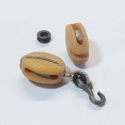
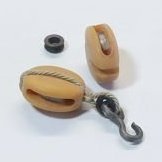
You will have to show me when you drop by the shop. Today I am preparing to start the running rigging. The first thing I did was make all of the hooks and also prepare the traveler ring for the jib rigging. The traveler ring has both a shackle and a hook. A simple version is shown on the plans but I will be using the traveler ring available "ready made" at Syren Ship Model Company. It is ready to use right out of the package. It has a 3/8" inside diameter. They can be finicky things to make.
Now if I only remembered to slip one of these on the bowsprit before I finished the standing rigging!!!! No worry though. I will be able to assemble one in place.
Chuck
-
 Chuck got a reaction from Hubac's Historian in How to deal with badly drawn plans?
You cant use auto trace...its just not accurate. It also creates too many nodes in your lines. Unfortunately there are no shortcuts and these "quick-fix" auto functions are just a way to do the job quickly and rather sloppily. The only way you will be able to really do an accurate job is to import the image and trace over it while making corrections yourself. Then as Druxey said, use diagonals and waterlines to fair and correct your traced lines. It is a very time-consuming process but its the only way you will be sure its correct before you start making sawdust.
I usually import an image and scale it to whatever the scale is I am working on...say 1:48. But others find it easier to make the drawing full size so they can use the real measurements from Steele or a builders contract. I use Corel Draw X8. It works great and once you become proficient with using the dozen or so tools and functions needed it goes well. You can use small tricks and methods to speed up the process. I have taught several people over the phone how to use CD and in person. I can usually get them to the point where they can work on their own with good results in just a few hours. But they must understand lofting and fairing and ship design before they start using the software or the lack of architectural knowledge usually does them in. Its easy enough to learn the software....much more difficult and time consuming to learn and understand how draft frames and proof out and fair your lines, along with adding all of those important details not shown on an original draft or simple plan original.
In the image posted above for example, you can see the original draft I will begin drafting and tracing over. Also added to the workspace is an image of a similar contemporary model. This is also scaled up to the same size as the draft. Rather than flip back and forth to a photo on a different file or on paper, having the photo right above my work is an excellent and convenient reference. I can quickly examine the contemporary model for features not shown on the draft or incorporate and design my parts to mimic those on the model. For example, I can quickly use the model to design the joints between the stem and keel to closely mirror that models construction because its right above my workspace and not shown on the draft.
I usually have many more draft copies and photos in my workspace than shown here but this is how I work up a set of plans....once at a pont to fair the frames or correct inaccuracies in the draft I can hide those images while I create my own half-breadth plan or whatever third view I need to prove out my lines. I use waterlines and diagonals to correct my frames while creating my own Half breadth view from the body plan and sheer plan I traced.
Chuck
-
Chuck got a reaction from mtaylor in How to deal with badly drawn plans?
You cant use auto trace...its just not accurate. It also creates too many nodes in your lines. Unfortunately there are no shortcuts and these "quick-fix" auto functions are just a way to do the job quickly and rather sloppily. The only way you will be able to really do an accurate job is to import the image and trace over it while making corrections yourself. Then as Druxey said, use diagonals and waterlines to fair and correct your traced lines. It is a very time-consuming process but its the only way you will be sure its correct before you start making sawdust.
I usually import an image and scale it to whatever the scale is I am working on...say 1:48. But others find it easier to make the drawing full size so they can use the real measurements from Steele or a builders contract. I use Corel Draw X8. It works great and once you become proficient with using the dozen or so tools and functions needed it goes well. You can use small tricks and methods to speed up the process. I have taught several people over the phone how to use CD and in person. I can usually get them to the point where they can work on their own with good results in just a few hours. But they must understand lofting and fairing and ship design before they start using the software or the lack of architectural knowledge usually does them in. Its easy enough to learn the software....much more difficult and time consuming to learn and understand how draft frames and proof out and fair your lines, along with adding all of those important details not shown on an original draft or simple plan original.
In the image posted above for example, you can see the original draft I will begin drafting and tracing over. Also added to the workspace is an image of a similar contemporary model. This is also scaled up to the same size as the draft. Rather than flip back and forth to a photo on a different file or on paper, having the photo right above my work is an excellent and convenient reference. I can quickly examine the contemporary model for features not shown on the draft or incorporate and design my parts to mimic those on the model. For example, I can quickly use the model to design the joints between the stem and keel to closely mirror that models construction because its right above my workspace and not shown on the draft.
I usually have many more draft copies and photos in my workspace than shown here but this is how I work up a set of plans....once at a pont to fair the frames or correct inaccuracies in the draft I can hide those images while I create my own half-breadth plan or whatever third view I need to prove out my lines. I use waterlines and diagonals to correct my frames while creating my own Half breadth view from the body plan and sheer plan I traced.
Chuck
-
 Chuck got a reaction from Dubz in How to deal with badly drawn plans?
You cant use auto trace...its just not accurate. It also creates too many nodes in your lines. Unfortunately there are no shortcuts and these "quick-fix" auto functions are just a way to do the job quickly and rather sloppily. The only way you will be able to really do an accurate job is to import the image and trace over it while making corrections yourself. Then as Druxey said, use diagonals and waterlines to fair and correct your traced lines. It is a very time-consuming process but its the only way you will be sure its correct before you start making sawdust.
I usually import an image and scale it to whatever the scale is I am working on...say 1:48. But others find it easier to make the drawing full size so they can use the real measurements from Steele or a builders contract. I use Corel Draw X8. It works great and once you become proficient with using the dozen or so tools and functions needed it goes well. You can use small tricks and methods to speed up the process. I have taught several people over the phone how to use CD and in person. I can usually get them to the point where they can work on their own with good results in just a few hours. But they must understand lofting and fairing and ship design before they start using the software or the lack of architectural knowledge usually does them in. Its easy enough to learn the software....much more difficult and time consuming to learn and understand how draft frames and proof out and fair your lines, along with adding all of those important details not shown on an original draft or simple plan original.
In the image posted above for example, you can see the original draft I will begin drafting and tracing over. Also added to the workspace is an image of a similar contemporary model. This is also scaled up to the same size as the draft. Rather than flip back and forth to a photo on a different file or on paper, having the photo right above my work is an excellent and convenient reference. I can quickly examine the contemporary model for features not shown on the draft or incorporate and design my parts to mimic those on the model. For example, I can quickly use the model to design the joints between the stem and keel to closely mirror that models construction because its right above my workspace and not shown on the draft.
I usually have many more draft copies and photos in my workspace than shown here but this is how I work up a set of plans....once at a pont to fair the frames or correct inaccuracies in the draft I can hide those images while I create my own half-breadth plan or whatever third view I need to prove out my lines. I use waterlines and diagonals to correct my frames while creating my own Half breadth view from the body plan and sheer plan I traced.
Chuck