
Supplies of the Ship Modeler's Handbook are running out. Get your copy NOW before they are gone! Click on photo to order.
×
Chuck
-
Posts
9,450 -
Joined
-
Last visited
Reputation Activity
-


-
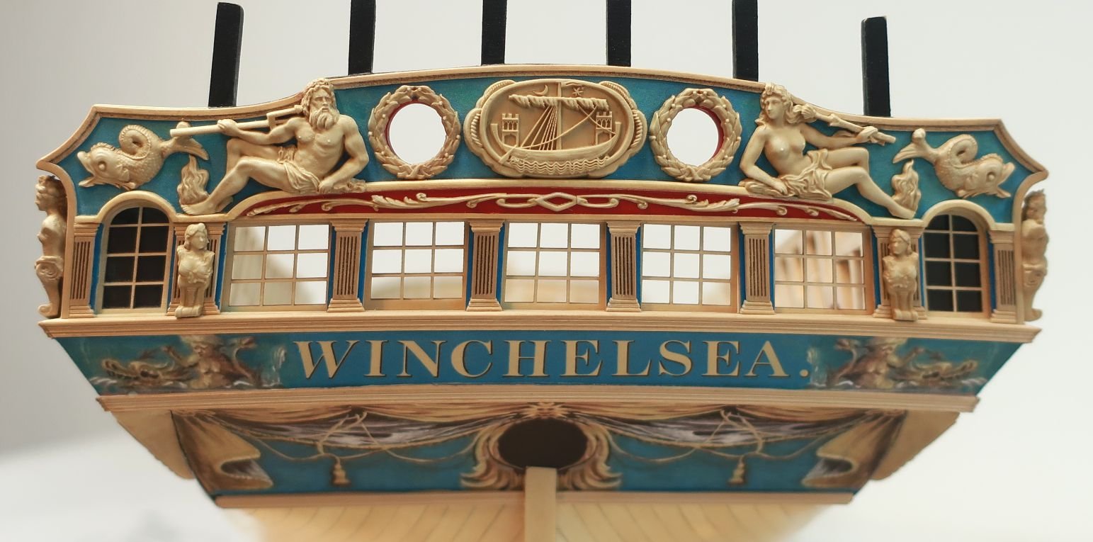
Chuck got a reaction from FrankWouts in HMS Winchelsea by tedrobinson2000 - 1:48
Its in there....take a look at that chapter again. Also mentioned in the instructions is another filler piece I recommend you place along the stern post that is faired to the hull shape. Its all in there so take a bit more time to examine the images and instructions. Adding that length of faired strip along the sternpost and glued to the bulkhead former will save you a lot grief later when planking.
Should you recognize something that doesnt seem right or is missing I can only strongly urge you to ask those questions in your log before moving forward There are probably a dozen or so group participants that would be able to direct you to the info and post many images like those below. They are readily available.
I would suggest trying to correct any twist on that stern before moving further ahead. That will only get harder to rectify as more planking is completed. Have you tried more "L" brackets against the former at the stern to force the stern transom into alignment? Perhaps just one on the Starboard side to force your transom a bit to port....after planking it should stay there.
Chuck
-
Chuck got a reaction from FrankWouts in HMS Winchelsea by tedrobinson2000 - 1:48
Ask the question before you proceed.....That is my only suggestion....
Its all here and a wealth of info and experience from participants who are well ahead of you. Take advantage of the fact that this is a group project. Its a wonderful thing.
Chuck
-
 Chuck got a reaction from Stuntflyer in HMS Winchelsea by tedrobinson2000 - 1:48
We are here if you need us!!! Post more frequent updates of less progress and I am sure it will be easier for us to fore-warn you of future issues. We have all been there so its something the group routinely does for other participants.
Just remember to have fun with it.
-
 Chuck got a reaction from bdgiantman2 in HMS Winchelsea 1764 by Stuntflyer (Mike) - FINISHED - 1/4" scale
At a loss for words Mike....She is a beautiful model. So sweet. And it was fun getting in the trenches with you on it for so many years.
Chuck
-
Chuck got a reaction from FrankWouts in HMS Winchelsea 1764, by Gary B
That looks very good Gary. It will be a relief once its all done. Dont be afraid to sand the hell out of it.
Chuck
-
 Chuck reacted to Tigersteve in Mayflower by Tigersteve - Model Shipways
Gratings for the upper deck were completed using 3/16” cherry grating strips from Model Expo. The coamings were created first using a jig I created from previous projects.
The quality of the grating strips were good. It was a tedious and frustrating process. The center gratings are slightly askew. This being my second assembly of this portion, I opted to not redo them. They will be obscured by the ships boat anyway.
Steve
-
Chuck got a reaction from FrankWouts in HMS Winchelsea - FINISHED - 1764 - by Chuck (1/4" scale)
You are welcome. I will be the first to admit that I take forever to design and produce these projects. I cant rush through them. So many kit mfgs seem to announce the availability of new kits every few months. That is something I can never do. This next project will be a bit of wait. Hopefully worth it. POF projects have triple the parts and more complexity. I prefer quality over quantity any day.
I am also trying out some new design features to make it easier to build.
Chuck
-
Chuck reacted to Edwardkenway in HMS Winchelsea 1764 by Edwardkenway- 1:48
I got several hours on Winnie, and removed the darker planks.
I gave a few of the suggestions a try, but in the end the last plank was taken out by running a brand new no.11 blade carefully down the seams and drilling two holes large enough to take my needle nosed pliers, carefully applied gentle pressure and the whole plank came out albeit with the attached false deck. I have some ply of the same thickness to replace that. I'd not edge glued the planks, so they came out easier and didn't damage any of the adjoining planks
The planks were cut, shaped and dry fitted
glued in and given an initial sanding
I'm happier with the result.
Thank you to everyone who commented or gave some advice on how to remove the offending planks, I much appreciate the help and encouragement.
Also thanks for all the likes and for looking in.
Cheers
-
 Chuck got a reaction from Archi in Sloop Speedwell 1752 by Chuck - Ketch Rigged Sloop - POF - prototype build
I wanted to show you guys a glimpse into the world of designing a kit. Especially one as complex as a fully framed project like the Speedwell. Its why I get so passionate about other folks just copying plans developed like this. It takes hours and hours to design each element. This forward cant frame jig is no exception. Its not like it ever gets done on the first try.
This jig and all of the parts needed for Speedwell up to this point require a level of precision above and beyond a typical POB kit. I actually had to make about nine forward cant frame jigs before I was fully satisfied. Each iteration was tweaked just slightly and laser cut. It was tested and measurements taken from all angles.....then adjustments were marked and redrafted....and repeated.
Here are some of the discarded jigs. All of them would have worked. But the last one worked best.
Things should progress quickly now until it comes time to make the aft cant frame jig. Using a copy of the plans helps identify issues as well. Here you can see the working plan cut and in position and how it matches up pretty darn close to all the framing. Once drawn, you have to tweak the parts to account for the laser kerf and sanding of char etc.
-
Chuck reacted to Blue Ensign in Medway Longboat 1742 by Blue Ensign - FINISHED - Syren Ship Model Company - ½” scale
Thank you Ryland and Bob, it's good to have your respective works to refer to. 👍
Post 11
The three required strakes of this version are now fitted, but not fully fettled.
I found that the planks altho’ pre-spiled did require a fair amount of tweaking to get them to fit.
0270
0267
0263
The second strake below the sheer (plank15) proved trickier to fit.
Starting with the port side, once around the bow curve it did not readily sit down against the sheer plank. Repeated bending and some sanding was required to get the plank into position.
0266
The aft section (plank16) was a little easier but did require some sanding and bevelling along the section between frame 8 and the transom. Mid way along a slight curve was induced, and from frame 8 a slight twist is also required where the plank starts to curve beneath the transom.
0265
The forward plank on the Starboard side also required similar treatment. The aft section (16) proved problematic, I just couldn’t get rid of an annoying gap, so the plank was scrapped and a replacement cut which went on with minimal sanding and bevelling.
The third strake bow plank (13) is a long plank near 70% of the overall hull length.
0262
An almost instant disaster the end of the plank split along the grain where it fits into the bow rabbet, just where you don’t want it – under pressure at the bow.
Fortunately, there is sufficient sheet to cut replacements which is easily done using just a scalpel. Based on the trial fitting of the now replaced plank, the new plank can be tweaked before cutting to allow a little extra material for better sanding to fit.
0264
Both sides of plank (13) were re-cuts and it took me some time to get anywhere close to a tight fit.
0268
The same applied to the aft section where both planks (14) were re-fits.
0269
The one comforting thought is that the first and second strakes are covered by an extra layer of duplicate planks which form the wale, so there are in effect two chances to get it right.
This will be the next step.
B.E.
22/02/2023
-
Chuck got a reaction from FrankWouts in HMS Winchelsea 1764 by Stuntflyer (Mike) - FINISHED - 1/4" scale
At a loss for words Mike....She is a beautiful model. So sweet. And it was fun getting in the trenches with you on it for so many years.
Chuck
-
Chuck reacted to Freebird in Medway Longboat 1742 by Freebird - FINISHED - Syren Ship Model Company - 1/2” Scale
Hi Bob! Thank you for the compliments! Yup, lots of mistakes have been made along the way, some were fixed, others, well, you know. I have referred to your build log many times for the rigging, it has been very helpful! Your Medway is a fantastic build and has been an inspiration! Medway has been an extremely fun build and I have learned a lot of new skills. For my first build, I’m pretty pleased on how she’s coming out. My hat is off to Chuck for his awesome design and endless help. I’ve been building models as far back as I can remember, and I’ve never come across a mentor and designer like Chuck who so freely shares his knowledge. Because of him and the many talented builders on MSW, like yourself, I’ve been able to pursue something I’ve wanted to do for many years. Thanks again Bob!
And a big thank you to All for stopping by and all the likes!
Best Regards …. Rick
-
Chuck reacted to Kusawa2000 in HMS Winchelsea 1764 by Kusawa2000 (Mike Draper)
Frank: Actually yes! I am nearly done the first planking of the wales as well as the planking below the Stern gallery windows. I have also milled the boxwood I will be using for the hull planking. I used the Alaskan cedar for the wales and below the windows as they will either be painted or covered in ornamentation. But I got access to some amazing boxwood and its colour and hardness was perfect for the Winnie.
Also, as Chuck outlined in his chapter 2, that first wale is critical in getting it aligned. It was a real hassle getting it just right. I had a few false starts. But after all of that framing work it was a real pleasure to get some planks on her.
I will post some pictures as soon as I can get the wales done and get that first plank using the boxwood.. Im stoked!
Mike Draper
-
Chuck reacted to Wxchsr in HMS Winchelsea 1764 by Wxchsr - 1:48
Going great. Back to the point of starting the port framing. It was at that point last time I noticed the issues, I’m not seeing those this time, so the added precision has made all the difference.
-
Chuck got a reaction from FrankWouts in HMS Winchelsea by Beckmann 1/48
Wow that looks so good. I am loving what you did with this model. Well done.
-
Chuck got a reaction from FrankWouts in HMS Winchelsea by Beckmann 1/48
Beautiful…getting close to the finish line now.
-
Chuck got a reaction from FrankWouts in HMS Winchelsea 1764 by Kusawa2000 (Mike Draper)
Time to put some meat on those bones. That a great foundation for planking.
-
 Chuck got a reaction from Saburo in HMS Winchelsea 1764 by westwood - 1:48
I think they look great. Glue them on.
-
-
Chuck got a reaction from Saburo in HMS Winchelsea by James G (Jim) - 1:48
Lite ply always. Just make sure it isnt warped.
-
 Chuck got a reaction from FrankWouts in Sloop Speedwell 1752 by Chuck - Ketch Rigged Sloop - POF - prototype build
Took a break from restocking inventory to work on the model.
Forward cant frames....
The jig is first. BUT before you do anything, make sure the hull is positioned correctly on your build board. Line up the forward face of the last square frame with the corresponding lines on your baseboard. Slide it forward or aft if needed because you will be lining up the cant frame jig with your baseboard plan.
Take the laser cut square shown below and glue it to the underside of the last square frame cross piece. The laser etched guide on the square should help you with positioning it.
It will look like this. The fore cant frame jig is resting on top which will be added next.
Place the cant frame jig in position. The "puzzle piece" connection was left a little loose on purpose to give you some room to adjust it. Not a lot...its not a sloppy fit. But there is just enough room to adjust it side to side based on what we will do next.
This next step is super important....
Use your square to check that the notches in the top of the jig match the cant frames as drawn on the baseboard. The machine square I have actually fits right into the slots making this pretty easy. I got these from MicroMark. They are pretty common and if you have one this works perfectly. There is also a laser etched line down the center of the jig to help with alignment.
The forward edge of each slot....should line up with the aft edge of the cant frames as drawn on the baseboard. This is important. Its worth mentioning it again. The forward edge of each slot....should line up with the aft edge of the cant frames as drawn on the baseboard. See below. Check this on both sides of the hull obviously. Try and get it as close as you can.
Then tape the cant frame jig to the first square frame cross piece. Remember, there is some wiggle room so you can adjust as needed to get your slots lining up as close as possible. But dont be upset if they are off by a hair. Just get them as close as you can.
Next up, and you will do this for every cant frame....take the two strips laser cut and marked "1", and glue them into the forward slots. Make sure the numbers face forward. Slide them all the way into the slots. This is also important. The top of these strips should be flush with the top of the jig.
Note the laser etched line on the forward side. This line references the outboard edge of each cant frame. We are starting with the most forward pair for a few reasons. The most important being to help firm up the cant frame jig at the correct height and "lock" it into position. Every cant frame after this first pair will also have a corresponding numbered strip. You will be progressing aft with one cant frame pair at a time. Just like this.
You can see below how this jig will work. I have placed the square against the strip. Note how it rests against the forward edge of the strip and at the same time...The bottom of the square shows it lining up with the cant frame drawing on the baseboard. The angles match. We are talking about the aft edge of the cant frame. The cant frames will all sit against the forward edge of those numbered strips.
Below you can see the forward pair of cant frames glued into position. I of course sanded the char off the edges first. But dont sand the heel of the cant frame. Only remove the char from the inboard and outboard edges. These frames are cut to length with tight tolerances so dont sand the heel end that gets glued to the angled wedge on the apron.
Note how the outside edge of the cant frame lines up with that laser etched reference line that was on the numbered strip. Also note that the top of the cant frame is flush with the top of the numbered strip. This first cant frame is important because it locks the jig in at the correct height as well and stiffens it all up.
One down and ten to go. Repeat this process working aft with the remaining cant frames. Remember to just work on one cant frame pair at a time. Some of these forward cant frames are made in two pieces with a simulated chock like the frames. We shall discuss this when I get that far.
Next up will be cant frame "2". You can see the numbered strips sitting on top ready to go. But now that the jig is in position its pretty easy and should go quickly. No need to sand the bevels into the heels of each cant frame. All you really have to do with each cant frame is sand off most of the laser char on the inboard and outboard edges and glue it into position. The apron has all the correct angles in for each cant frame already.
Let me know if you have any questions.
-
 Chuck got a reaction from Mark P in HMS Tiger 1747 by Siggi52 - 1:48 - 60 gun ship from NMM plans
Wonderful work.
Chuck
-
 Chuck got a reaction from PeteB in Sloop Speedwell 1752 by Chuck - Ketch Rigged Sloop - POF - prototype build
I wanted to show you guys a glimpse into the world of designing a kit. Especially one as complex as a fully framed project like the Speedwell. Its why I get so passionate about other folks just copying plans developed like this. It takes hours and hours to design each element. This forward cant frame jig is no exception. Its not like it ever gets done on the first try.
This jig and all of the parts needed for Speedwell up to this point require a level of precision above and beyond a typical POB kit. I actually had to make about nine forward cant frame jigs before I was fully satisfied. Each iteration was tweaked just slightly and laser cut. It was tested and measurements taken from all angles.....then adjustments were marked and redrafted....and repeated.
Here are some of the discarded jigs. All of them would have worked. But the last one worked best.
Things should progress quickly now until it comes time to make the aft cant frame jig. Using a copy of the plans helps identify issues as well. Here you can see the working plan cut and in position and how it matches up pretty darn close to all the framing. Once drawn, you have to tweak the parts to account for the laser kerf and sanding of char etc.
-
 Chuck got a reaction from KARAVOKIRIS in Sloop Speedwell 1752 by Chuck - Ketch Rigged Sloop - POF - prototype build
I wanted to show you guys a glimpse into the world of designing a kit. Especially one as complex as a fully framed project like the Speedwell. Its why I get so passionate about other folks just copying plans developed like this. It takes hours and hours to design each element. This forward cant frame jig is no exception. Its not like it ever gets done on the first try.
This jig and all of the parts needed for Speedwell up to this point require a level of precision above and beyond a typical POB kit. I actually had to make about nine forward cant frame jigs before I was fully satisfied. Each iteration was tweaked just slightly and laser cut. It was tested and measurements taken from all angles.....then adjustments were marked and redrafted....and repeated.
Here are some of the discarded jigs. All of them would have worked. But the last one worked best.
Things should progress quickly now until it comes time to make the aft cant frame jig. Using a copy of the plans helps identify issues as well. Here you can see the working plan cut and in position and how it matches up pretty darn close to all the framing. Once drawn, you have to tweak the parts to account for the laser kerf and sanding of char etc.