michael mott
-
Posts
5,200 -
Joined
-
Last visited
Content Type
Profiles
Forums
Gallery
Events
Everything posted by michael mott
-
 Dan Just catching up. superb work on the ship a lot of interesting detail at a small scale. Michael
- 238 replies
-
- 7
-

-
- leviathan
- troop ship
- (and 2 more)
-
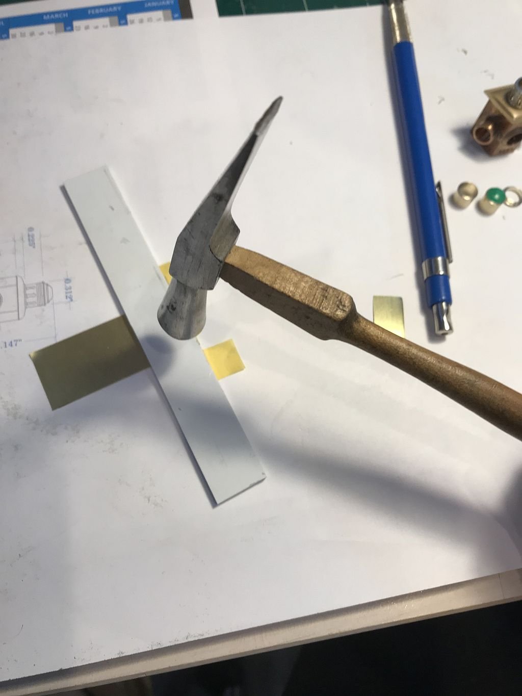
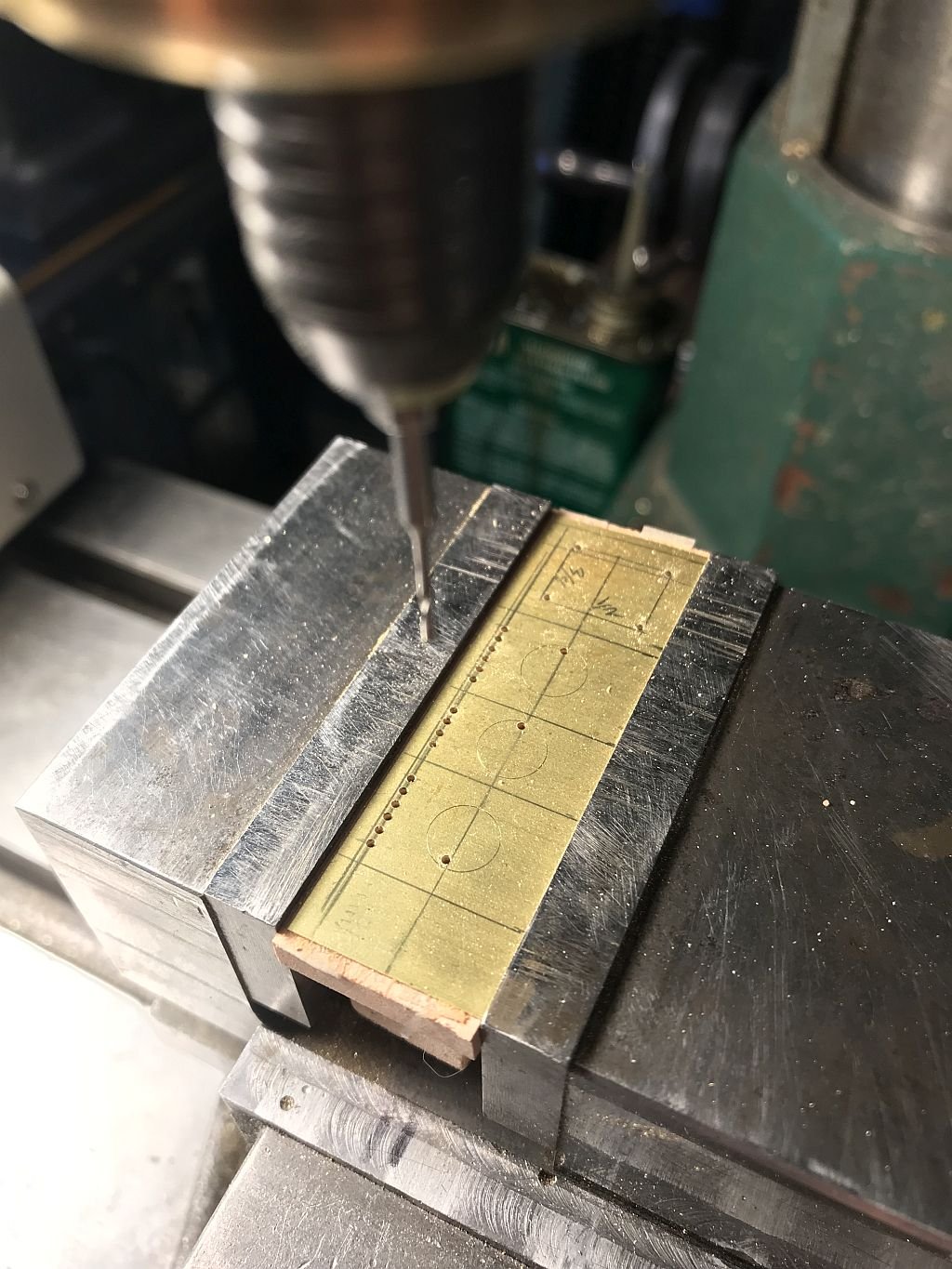
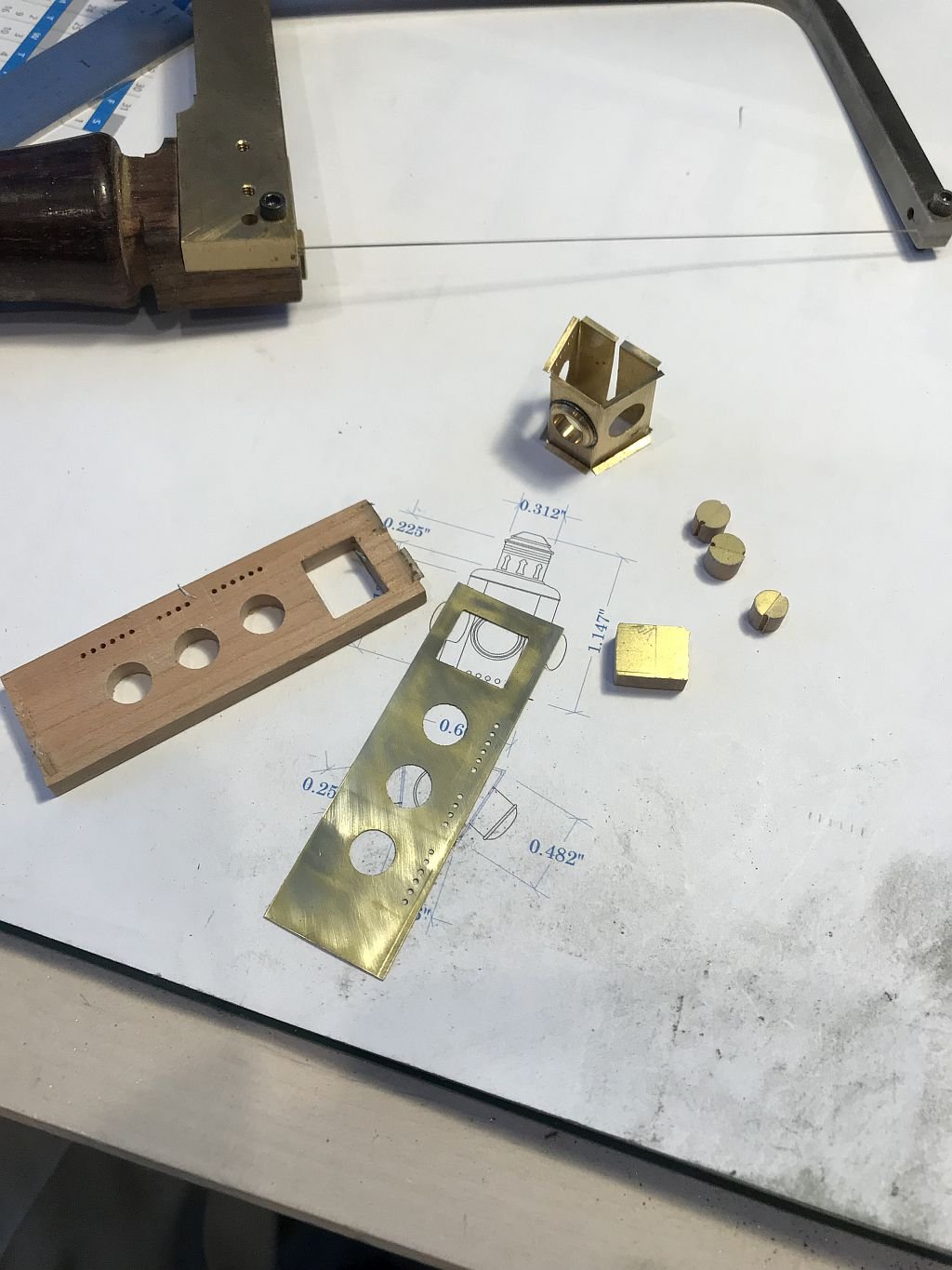
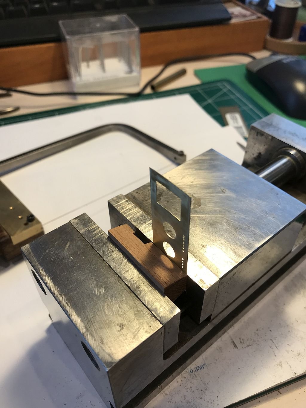
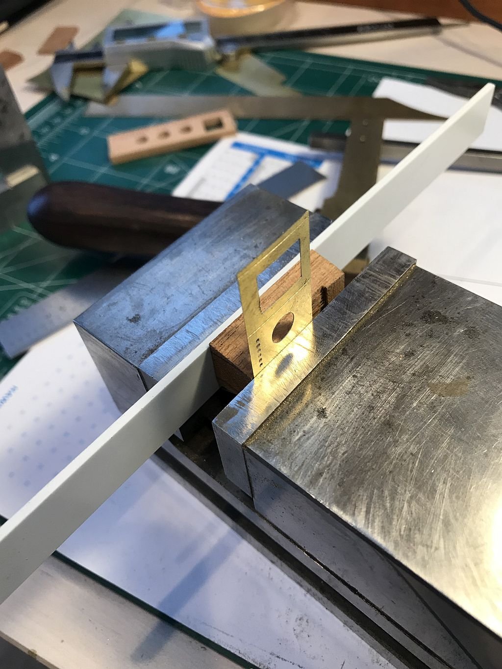
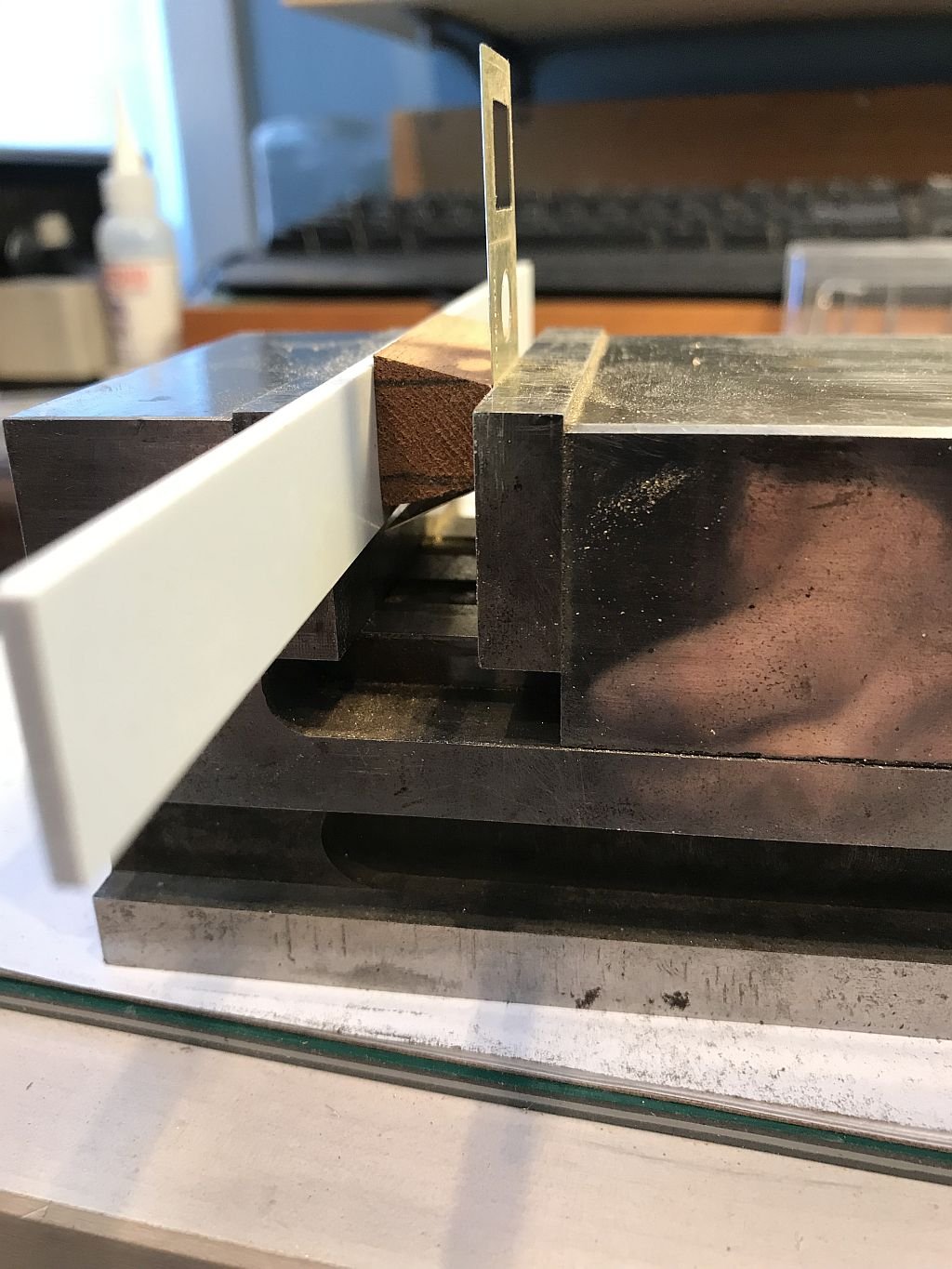
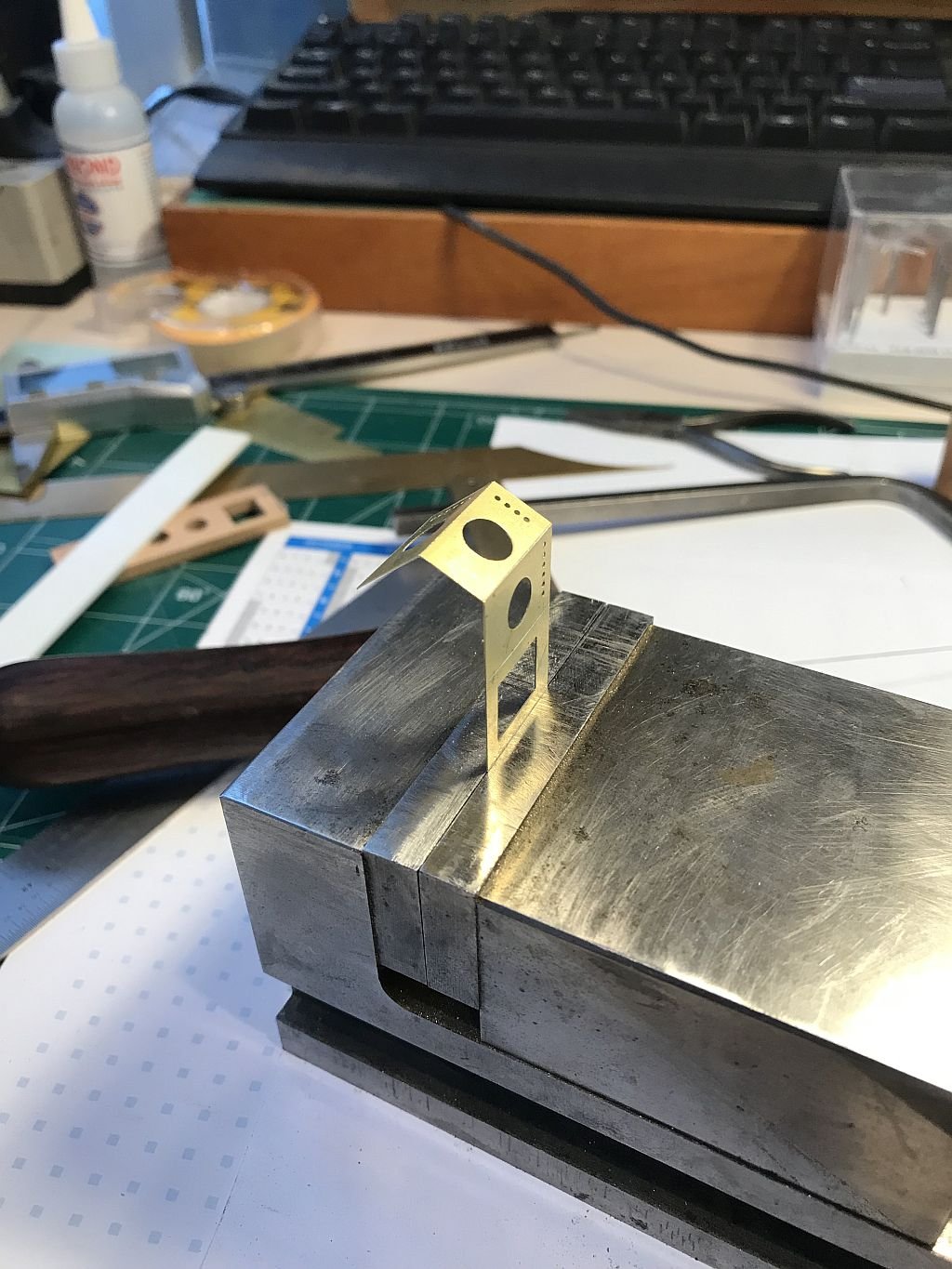
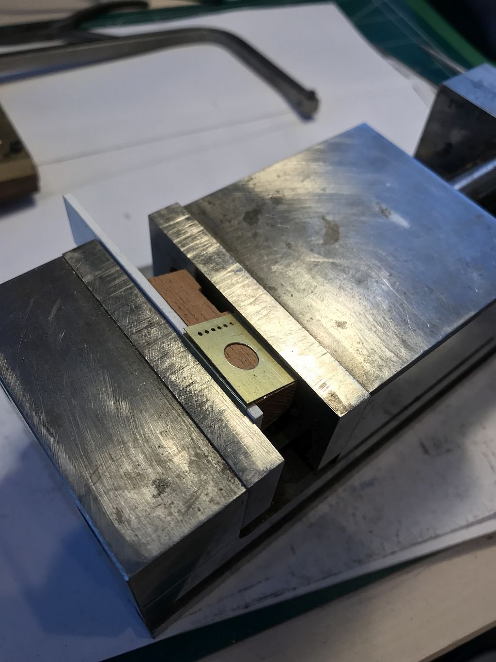
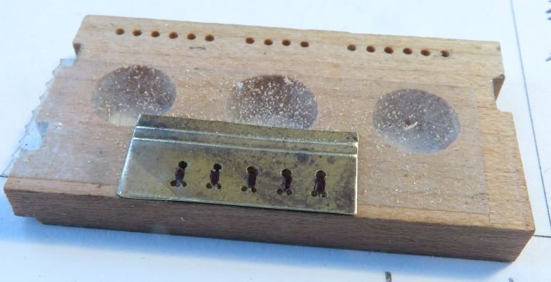
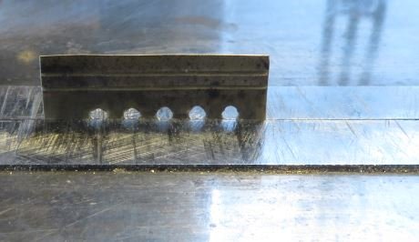
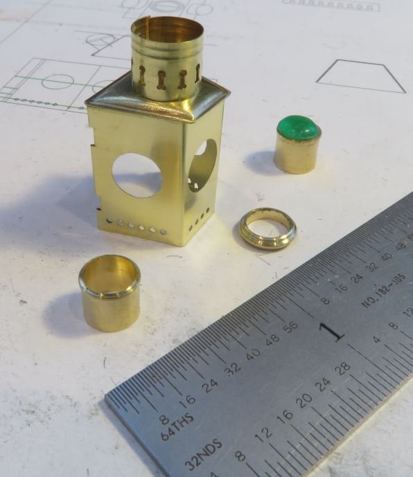
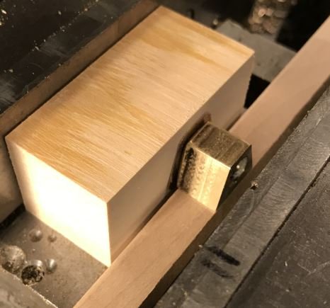
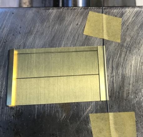
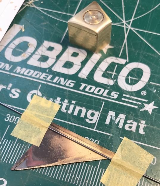
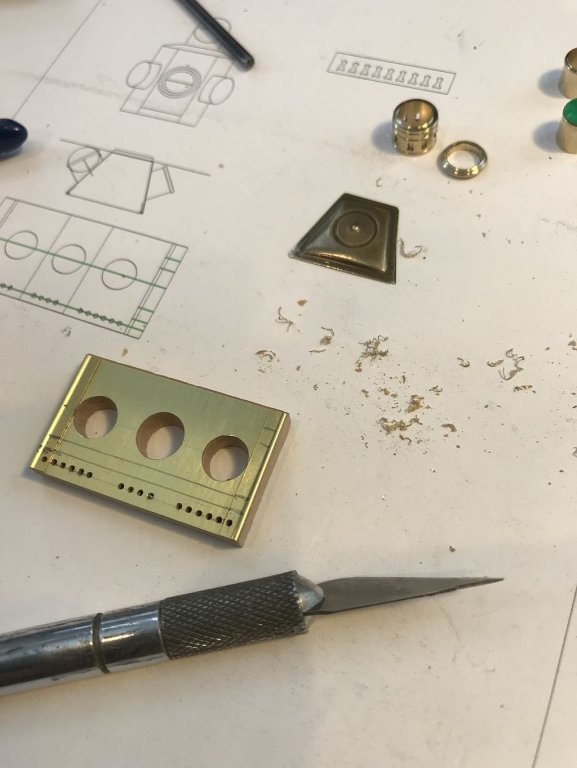
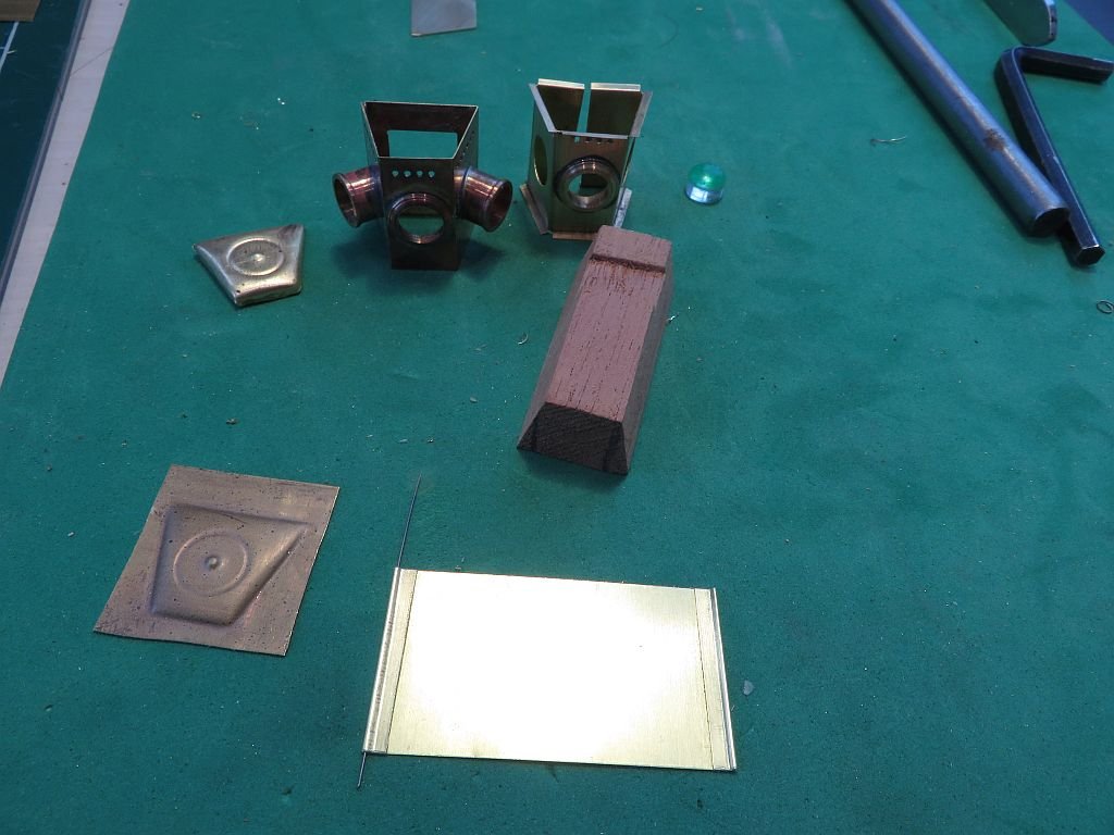
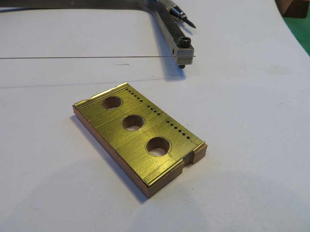
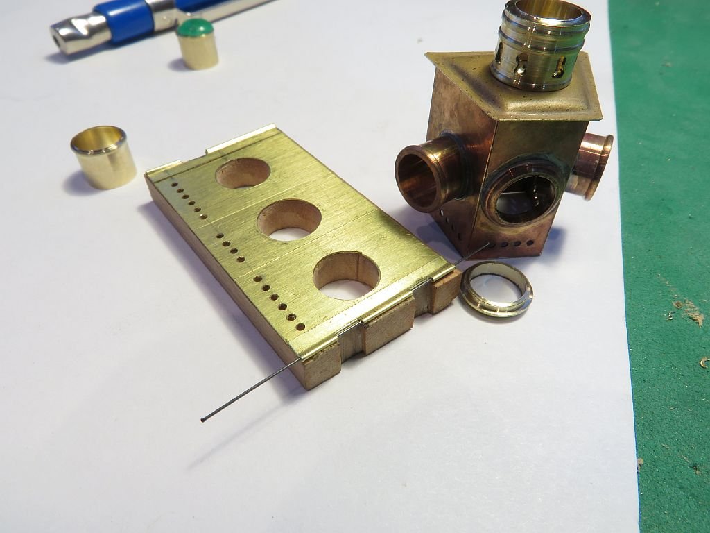
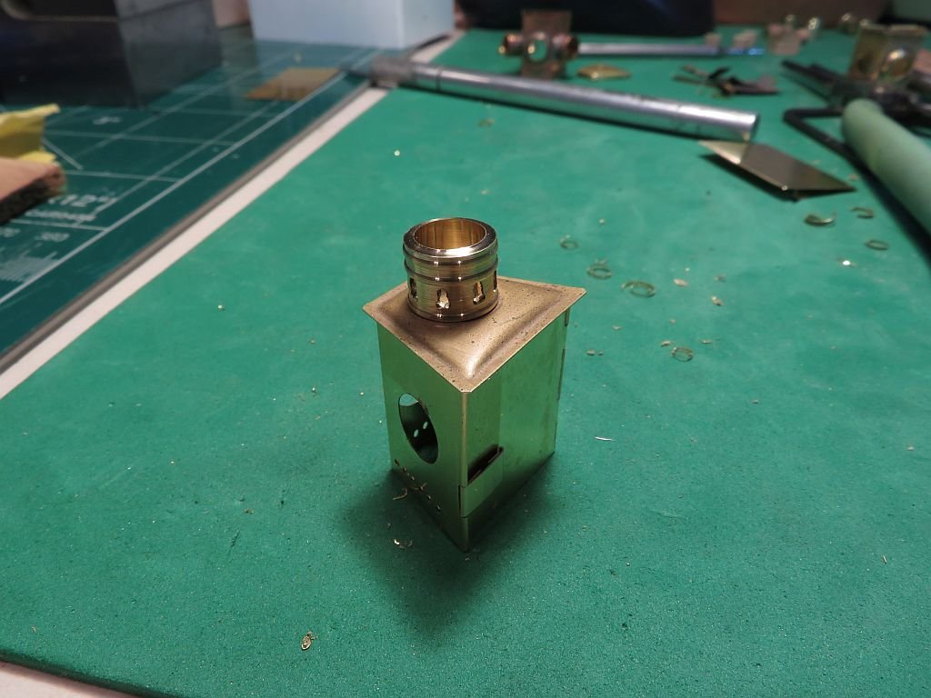
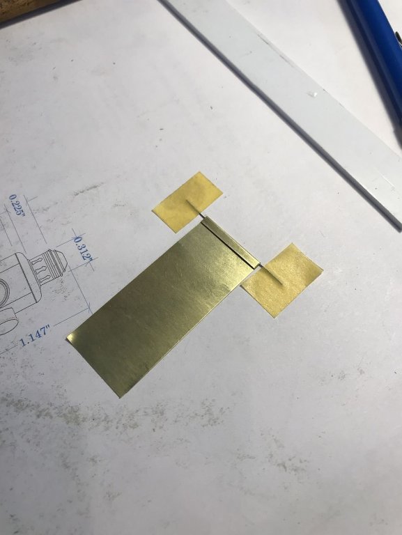
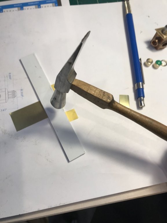
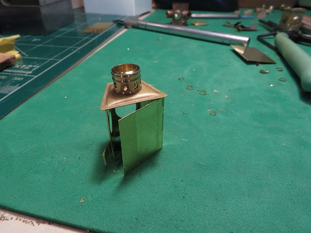
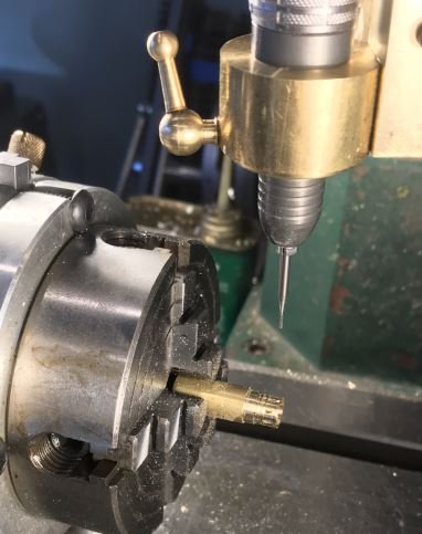
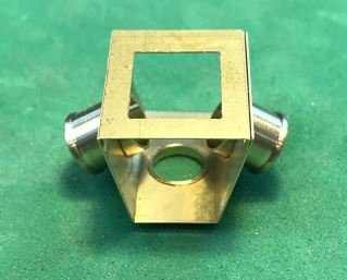
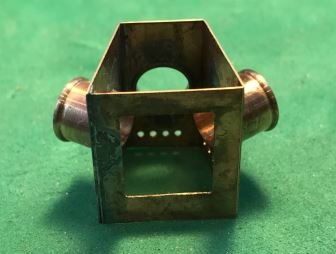
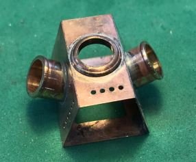
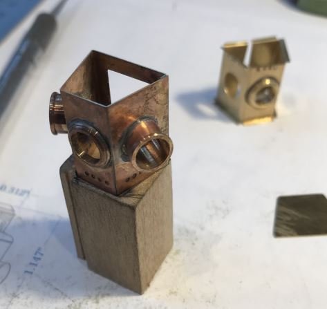
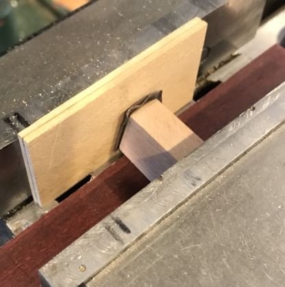
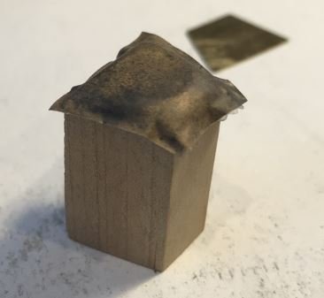
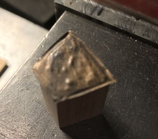
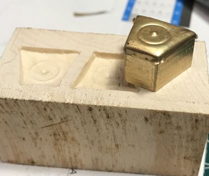
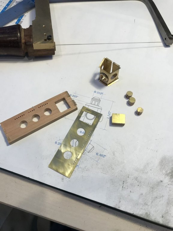
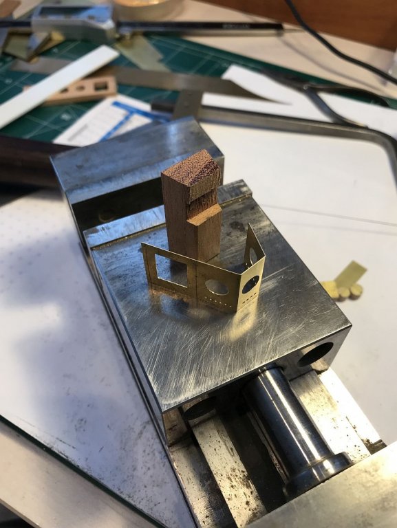
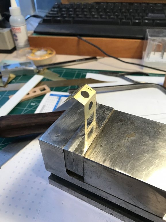
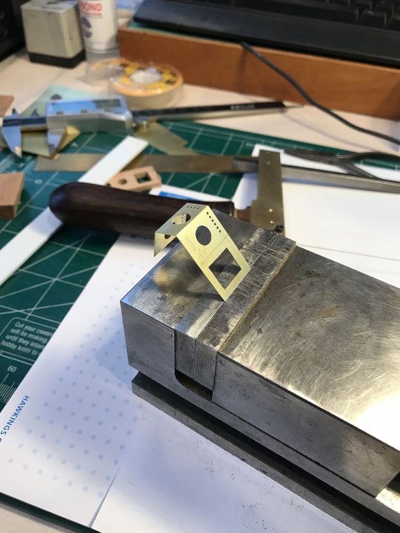
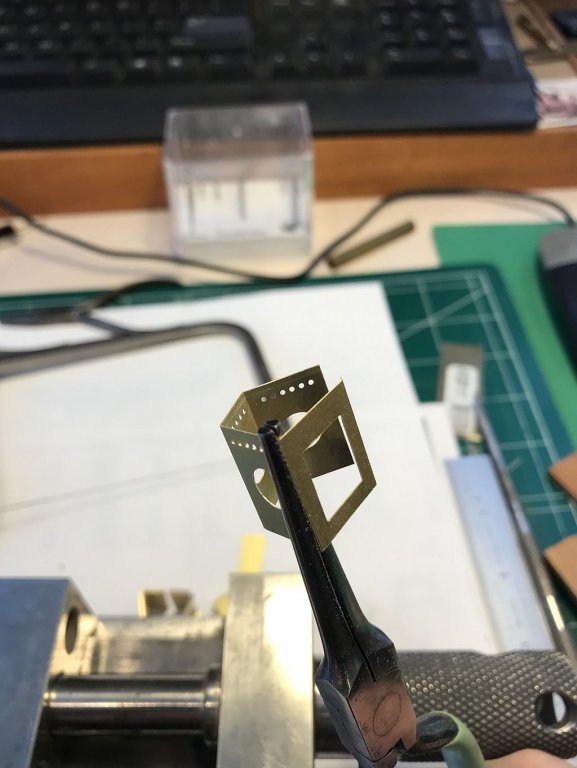
Ed thanks I appreciate you compliment. Hi Mark, the form for the top was all hand filed and polished. The brass form was placed in the milling machine vice so that the form was raised about 3/8 off the base with a wood spacer. The annealed sheet of .008" brass was stood up between the former and the smooth sanded block of Linden with the end grain facing the brass. The closing of the vice pushed the form into the brass and squashed the sheet and the form into the end grain of the linden. A shot of the mess on the bench. I wanted to see whether I could do a better job of the top of the lamp especially the tree like vents. So I did a new drawing in Cad and set up the measurements to be easily transferable to the dials on the mill/drill., but before that was done I wanted to see if I could form the two bands above the vent holes. A small piece of annealed brass was taped to the cutting mat and a rod of .021" music wire was taped into position then covered with a slab of I/8th inch brass and whacked with a hammer. I seemed to be successful, so I trimmed it up to see how the vent holes would work and then see how it curved into a tube. Teh trimmed piece was stuck to a piece of Cherry and using a combination of drills and burs I roughed out the holes. Then placed the piece in the vice to shape the holes some more with the fine rat tail file. It seemed to work in principle. so now to make the final part. It formed into a tube easily without distorting the brass looks terrible and dinged up because it was just a scrap. The new drawing gave me a better way of sequencing the body part so on to version 4 The folding was done on a hard surface which improved the results. After drilling and fretting out yet another three holes I am pleased with the results. The holes were slowly opened up with the exacto knife in the same way the you spin the knife around in the end of a tube to remove the burr. You can see the tiny shavings, it is slow but very effective way to set the holes. Next a top ring sheet for forming the vent tube was cut to match the cad Drawing and using an .8mm drill and an included 60 degree burr I was able to make a better looking series of vent holes. The top plate needed to have a hole cut and this was done the same way as the rest of the holes. The top plate was polished up and reduced the flange to better reflect the original. The vent tube was trimmed until it fit snug into a 5/16 diameter hole. a flanged retaining ring was turned for the base of the tube so that it could seat properly for soldering to the top plate. and an inner collar was turned up for the top of the tube. That's it for today. Michael
-
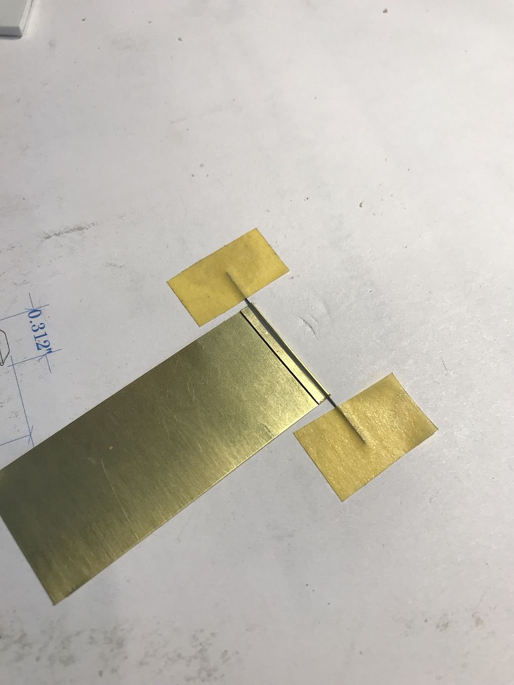
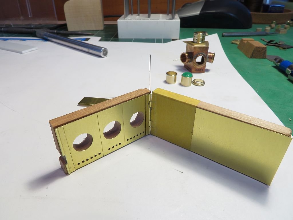
Well thank you Keith, and like all magic we have to practice our craft. Roger's photos this morning caused a rethink. The test is to see how well the integrated hinge will work. I went back to some .005" brass with some .011" music wire, a fold back with the wire placed at the apex and taped to stop it moving. Next a bit of evergreen to use to close the brass with a tap from the small hammer. The styrene is able to slip a little without damaging the brass. After both ends were folded it was back to the drilling and fretting out the three holes again. I also turned up some new lens tubes with a bit finer detail Using the jewelers saw to cut out the spaces for the hinge tab locations. then made a door using the same procedure. The hinge fitted better than I expected first time. The next task was to fold up the body this was a little easier not having to make the closing fold. again the same methods were used to make the folds. A small tab was folded to act as the closing piece. All dry assembled and the locking tab will need to be redone with the folds opposite to each other. The top is also new and follows the design of the original more closely. That's it for today. Michael

-
Stunning Work Gerald! The overall shot with the tools etc, Will the tools be on display as well as the models? Michael
- 281 replies
-
- 3
-
-
- falls of clyde
- tanker
- (and 2 more)
-
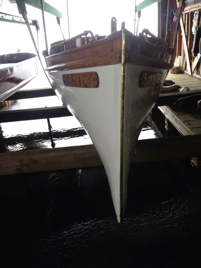
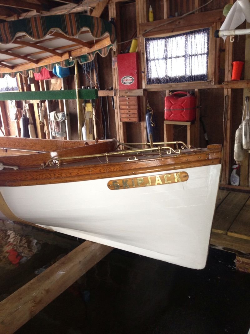
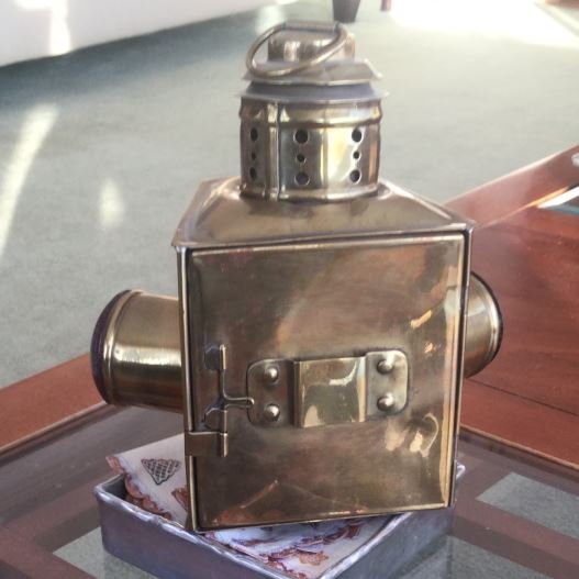
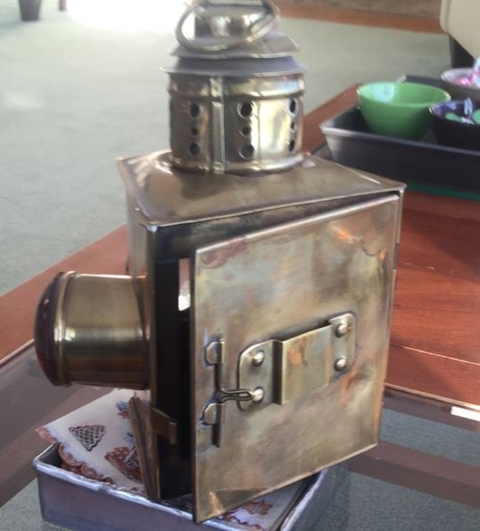
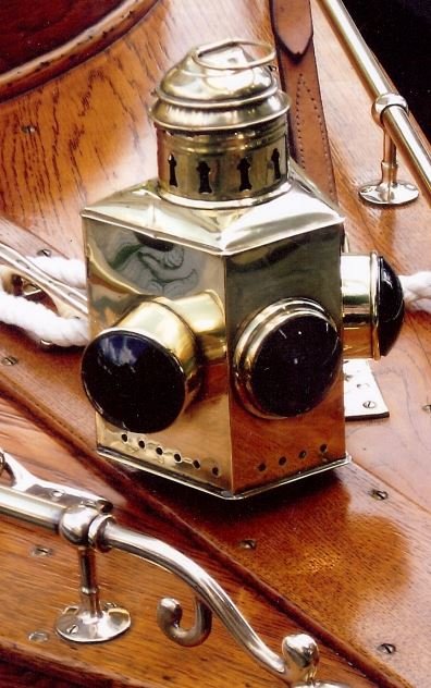
Hi Mark, The forward light was a clear lens and "It was a clear magnifier lens and was just a fwd facing headlight IN THEORY." Roger sent back this info this morning along with a picture of the door on the back of a light very similar to the one on Skipjack at the cottage. This was great because I was wondering how the lamp sat on the bracket and how big the door was. This was not shown on any of the light I saw on the internet search and the hinges are built into the bead along the back edges I did have the size of the lamp correct. Michael
-
GL Thank you for the information and the diagrams I will look into setting up something when I get a spare moment, (there are no spare moments in retirement) I remember something about using the carbon rod in a D cell battery or is that not done these days. Michael
- 219 replies
-
- 1
-
-
- smack
- cross-section
- (and 2 more)
-
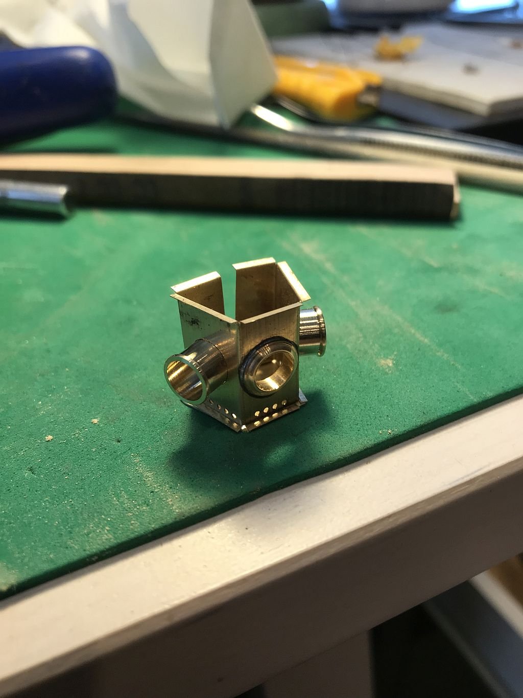
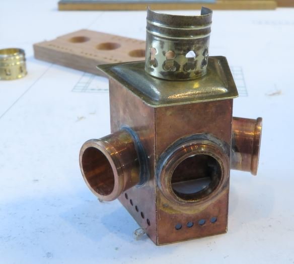
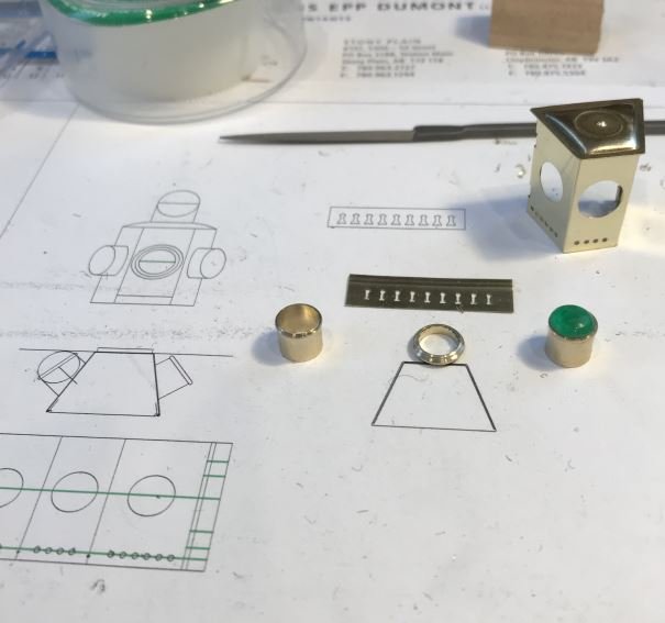
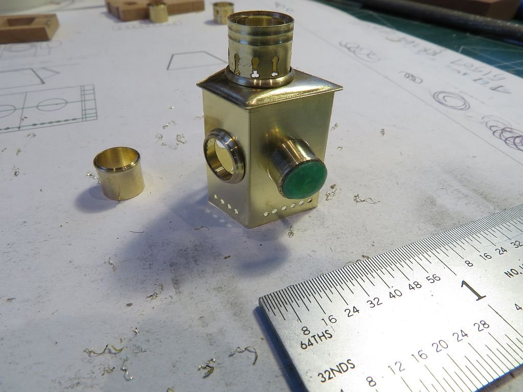
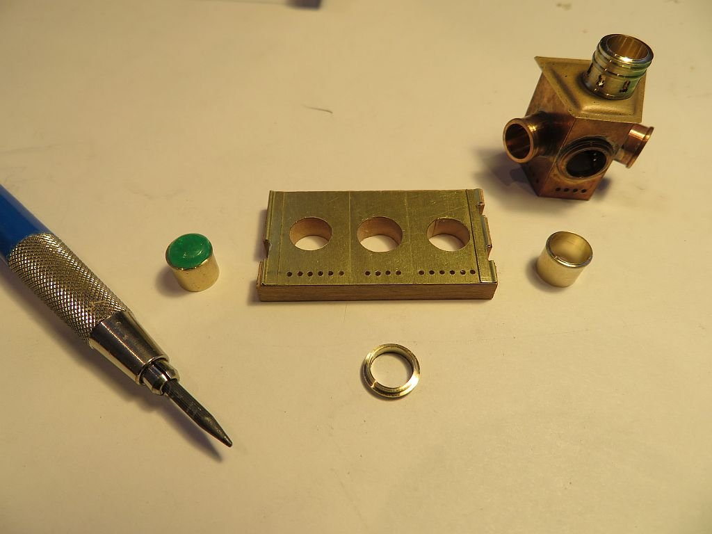
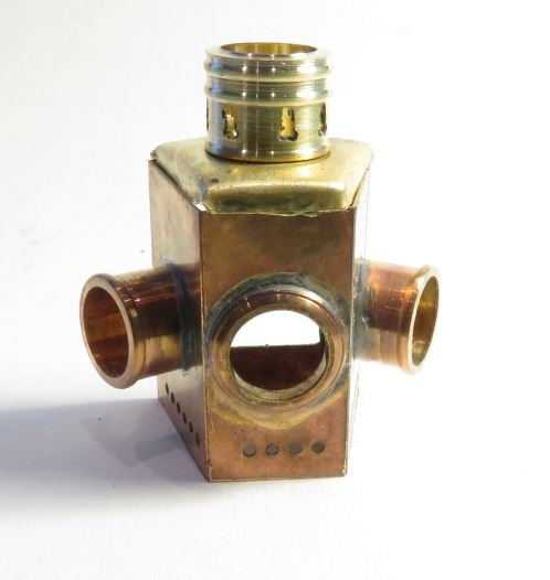
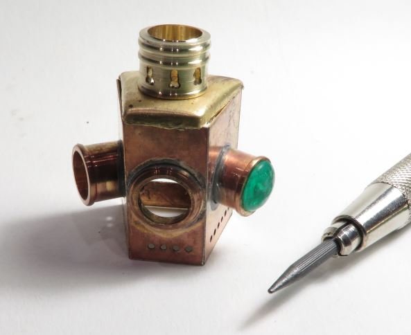
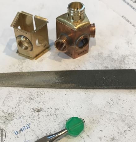
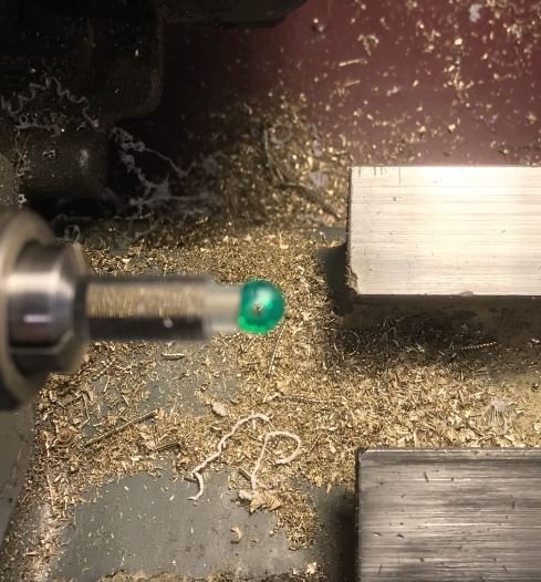
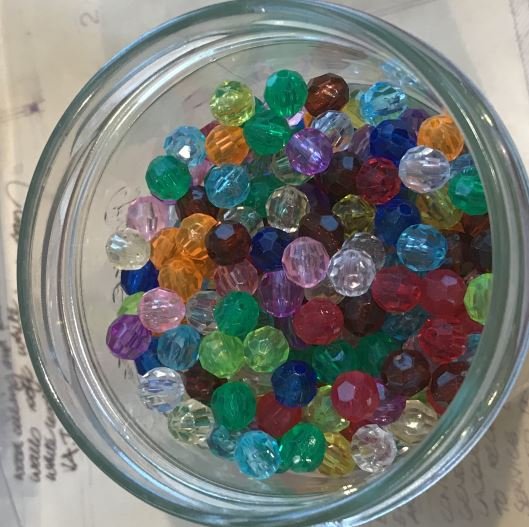
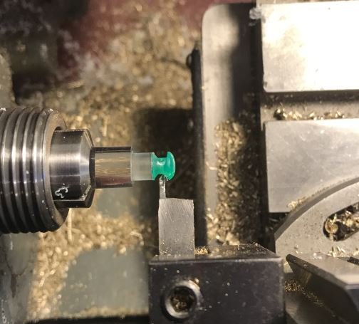
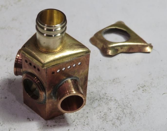
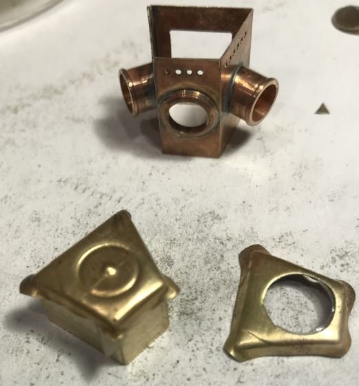
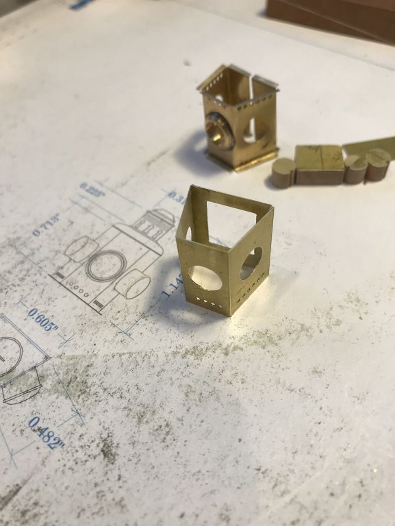
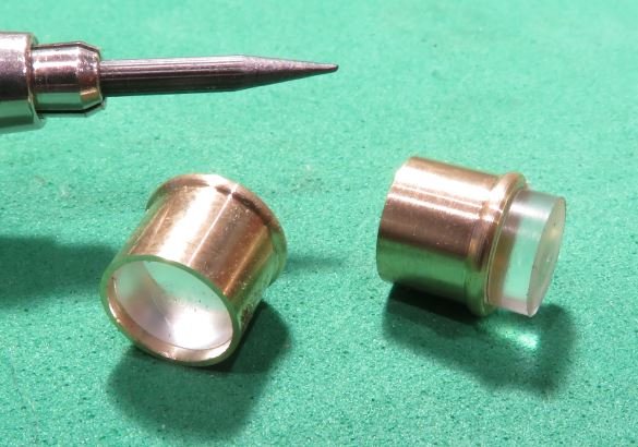
Thank you all for your compliments. I woke up thinking that I would have to make another top because the body is very slightly A symmetrical, so when I flipped it up the right way I was happy that it fit properly. I made a better top vent and put the holes in best I could with the small rotary table on the mill. So back to the lenses I went to Michael's today to get some glass stain to colour the plex to get the red and green. As I walked in there were all the coloured beads and for a song I got a box of a few hundred multiples colours of beads that were somewhere between 1/4 and 5/16" in diameter. The first thing was to put a small flat parallel to the hole so that it could be glued to a plex rod. It was wedged onto a tapered pin holder and with a course file slowly made a flat. this plastic melts easily if you file too fast and the friction makes the filing gummy. Next the flattened bead was glued to the plex rod for the initial shaping. Then the lens was machined off from the back side working slowly to let it cool between each cut. Once it was parted off the back side was polished up on a bit of card with some Novus #3 plastic polish. then glued back onto a short length of plex that was a slide fit into the lamp tube. The top will get soldered to a plate of .015 brass with the edges rounded to form a bead and the centre will be removed to allow the heat to rise to the top vent. Michael
-
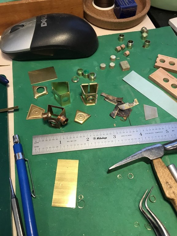
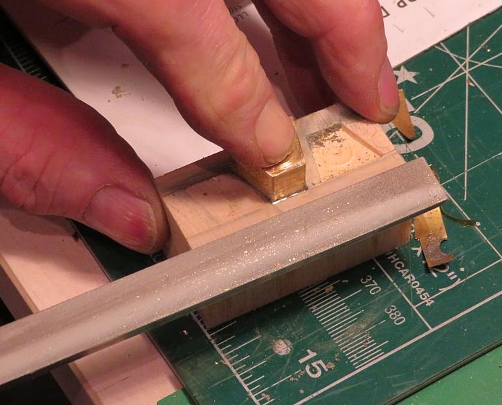
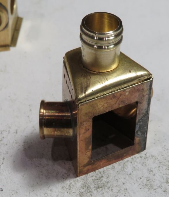
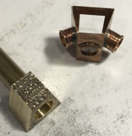
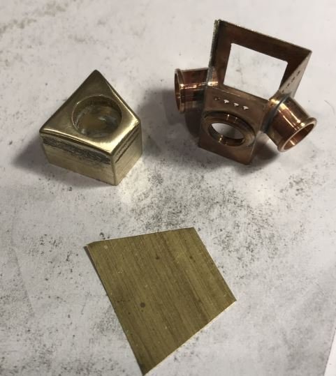
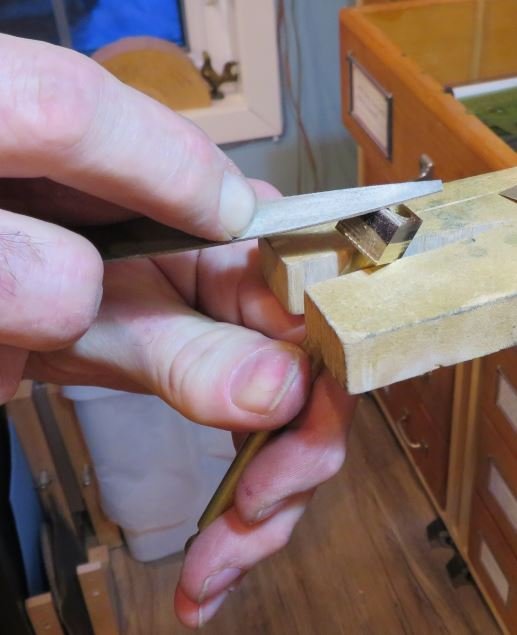
All the parts ready to solder, I had to shave the opening with the knife blade as if I was de burring to shape the hole to cause the lens holder to angle down Soldered with regular soft solder A new former to form the curved top was made from maple forced into some soft Jelutong it was ok but I wanted a crisper form so trued soe soft end grain maple it didn'r work and destroyed the form I made a new form out of brass and set it on a 5/16 rod with some locktite out of sequence picture of the raw block shaped and polished with a stub of 5/16 in filled in the hole, I did not use the short stub and made a longer one. A new block from some linden salvaged from an old drafting board a few years ago. a couple of tries with the new block and form with some anealed .005" A couple of presses later the form is deep enough. Filing off the excess with a safe edged file The journey so far, in this last picture the lamp is upside down, but i am pleased with the curved top. and a decent opening for the door. Michael

-
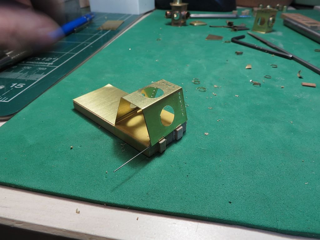
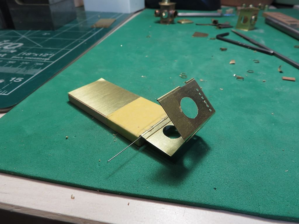
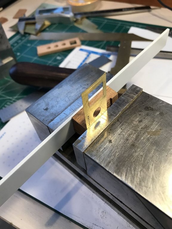
Thanks for all the kind remarks. Well like many of the other things that I have made over time on these models. Now that I know what I am up against I started over with some thicker brass sheet and laid it out differently. glued to block with double sided tape and drilled. cut out with jewelers saw Using the original for block. The second bend required an extra spacer Next a small tab on the back side needed to be folded for soldering the shell together Ready to fold the tab + closing the back require a different strategy so out came the long needle nosed pliers and the back was gently eased over with a flat block floding down the tab to match the back After some twaeking with the needle nose it all sat pretty nicely. Will continue in the next post Michael


-
A bit more progress the sheet is .005" The lenses have to go in after soldering. Michael

-
Thanks for your incredible tenacity is putting all this together Ed.... you must have been a rigger in a former life. And an incredibly steady hand in this one. It just occurred to me, with your comment about needing a few times to place a line without fouling, I'm sure that you have already thought of this, but if you harden the end of the line for an inch or so and also colour it red or some other definite contrast would that make it easier to thread the new lines through the maze? Michael
- 3,618 replies
-
- 5
-
-
- young america
- clipper
- (and 1 more)
-
Can you show us your equipment, it sounds like a good way to do some jobs. Nice sequence of pictures showing the way that you made the roller through the bulwark. Michael
- 219 replies
-
- 4
-
-
- smack
- cross-section
- (and 2 more)
-
Carl, short answer, no. But if you mean "sharing the ways that I do things" as teaching then I suppose you could call it that. It just seems to me that so many members of this forum have taught me so much about model ship building, that it only feels right to pass on some of the things that I do that might be helpful or useful to the other members. Sometimes it feel a bit like showing off but that is not the intent. One of the amazing things to me about this hobby, is that the members who share their knowledge here bring to the table without realizing it all of their own background knowledge, and each profession or workplace job teaches them skills and ways of seeing things that I don't. So in that sense we are all teachers. Thanks for the question Carl Michael
-
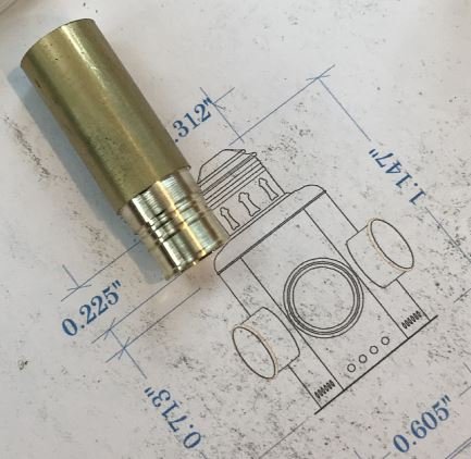
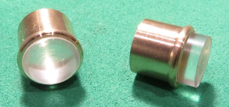
Made a start on the lamp turned up the two side lenses. I first machined some 5/16 brass to .284" for the flange then reduced the diameter to .254" then bored out to .246" and parted them off. Then turned down some 3/8 cell cast to .250" and relieved the section that would go into the tube until the tube just began slip on tightly, then pushed it up snug with the tailstock. Next parted off the plex leaving enough to shape for the front curvature with a form tool then polished it with some novus #3 on a bit of white card stock. Michael
-
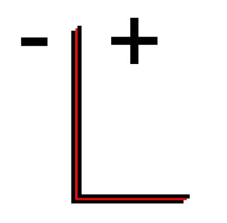
Hi Keith yes. My thought is to use a tiny led and make the deck bracket like a bi-metal strip so that when the lamp is pushed onto the part that stands up the front and back of the bracket are separated from each other but do not look that way. The two parts will sandwich an insulated strip. the lenses will be plex Michael
-
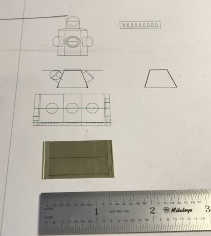
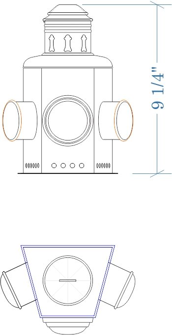
This is the plan for the Bow Lamp. Michael
-
Keith, Your use of the freezer bag as a clamp was brilliant. One of the great things about this forum is just this sort of sharing of out of the box sort of thinking that often goes on when we need to solve a problem with our models. Michael
-
While looking for some information about the lamp I came across this site which has some similar lamps and of course the name didn't escape me either. Michael
-
Kortes the blocks look wonderful, I am guessing that after soldering on the hooks you then filed the profile to create the rounded bulge where the pin passes through. Michael
-
Mark as far as I know the only ballast is the engine and Passengers. Keith I will think of you as I make them.... how about that? Michael
-
Kortes, thank you for you kind words. Further to your comment Roger this site which is for the Windsor boat works is building a new Dispro boat and I used their site as well to gain some insight into the Boats that were built around 1909-1915 Although there were all sorts of new innovations some things changed more slowly. Michael
-
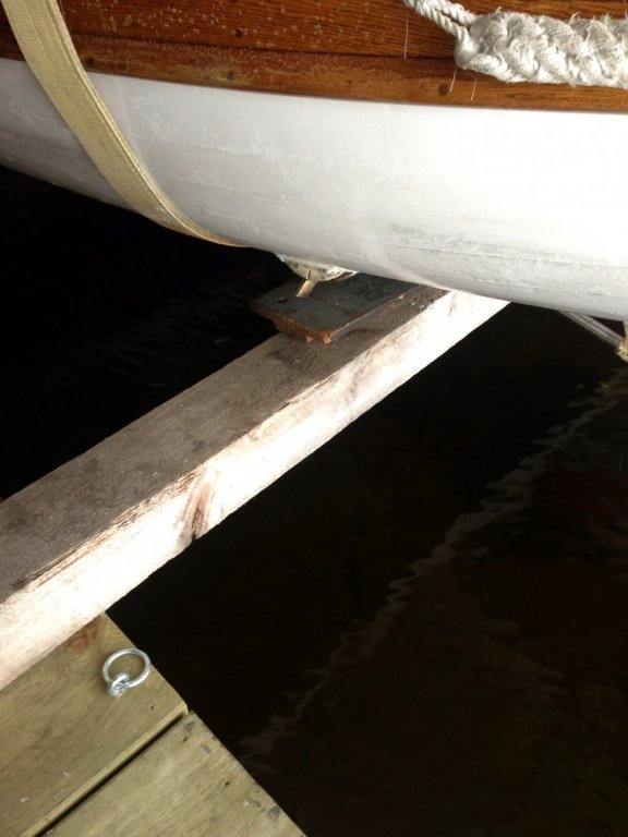
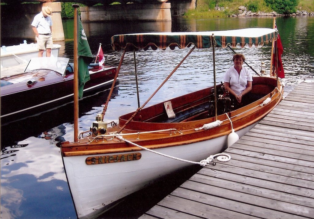
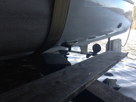
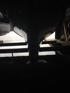
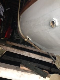
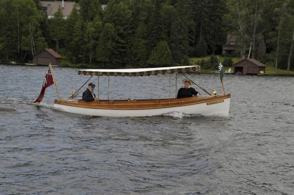
Hi Roger Thanks for your thoughts here are the photographs that I used to develop the lines. The bilges seem fairly soft but I am open to a clearer interpretation. I have searched for some lines of this boat, but other than heading out to Muskoka in the spring before Roger puts her back in the water this is all I had to go on. Michael