HOLIDAY DONATION DRIVE - SUPPORT MSW - DO YOUR PART TO KEEP THIS GREAT FORUM GOING! (Only 13 donations so far - C'mon guys!)
×


michael mott
-
Posts
5,195 -
Joined
-
Last visited
Content Type
Profiles
Forums
Gallery
Events
Everything posted by michael mott
-
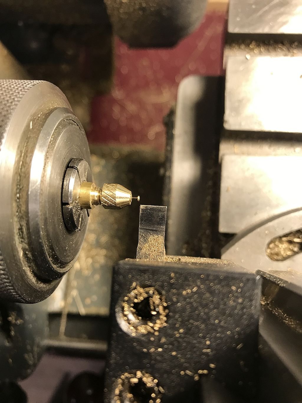
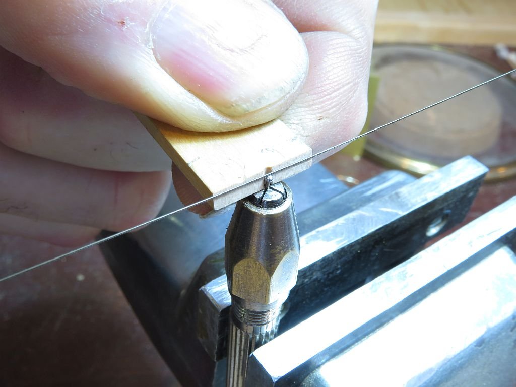
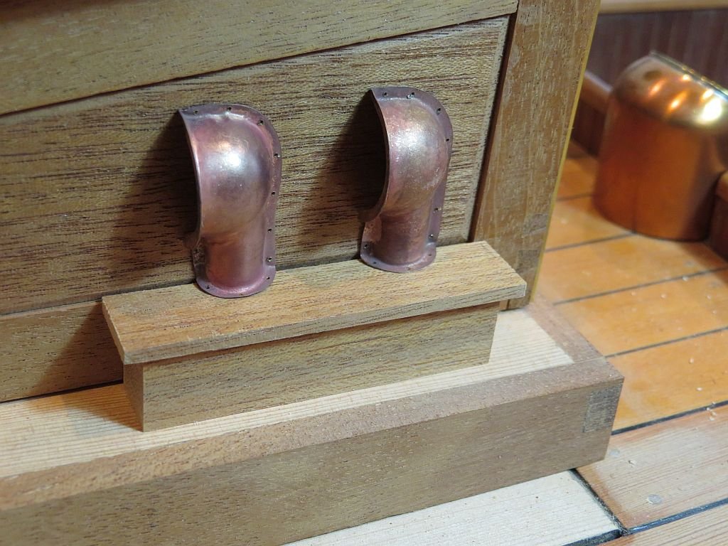
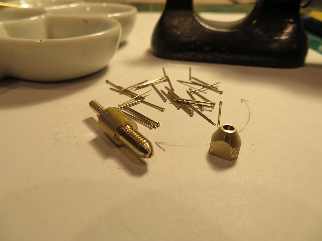
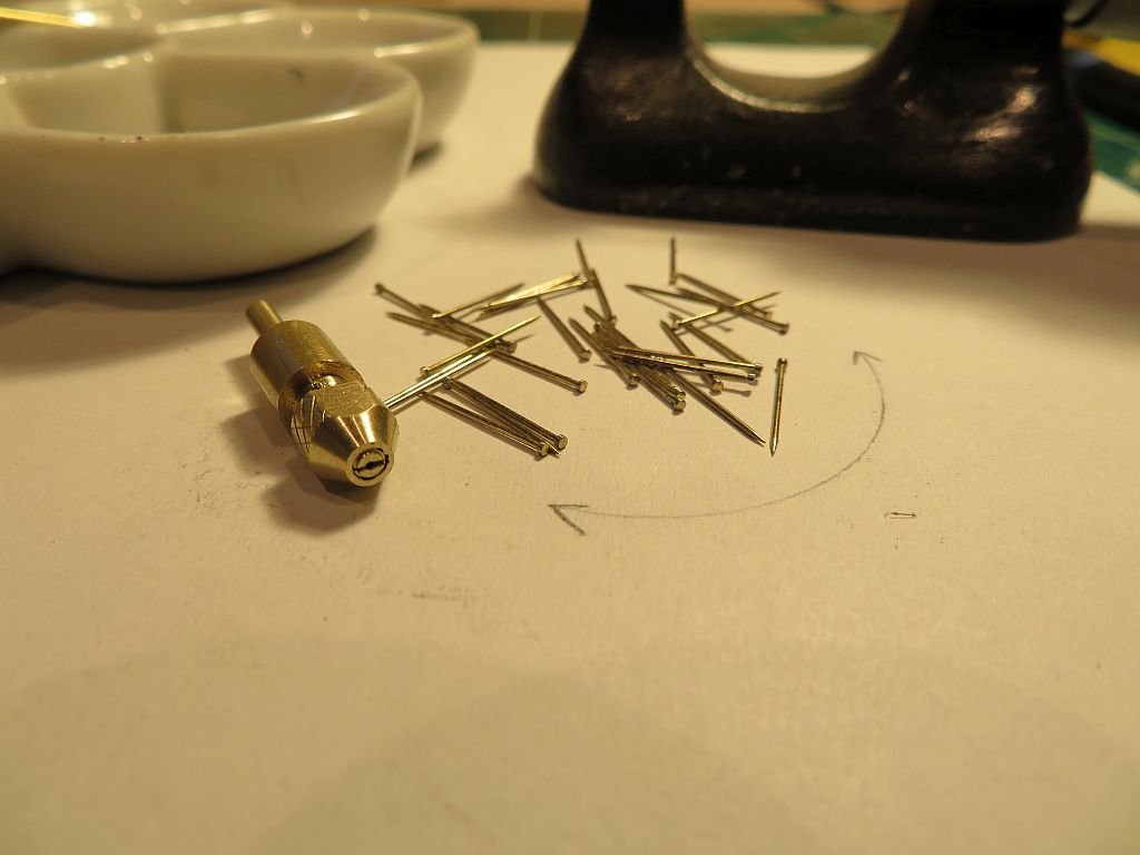
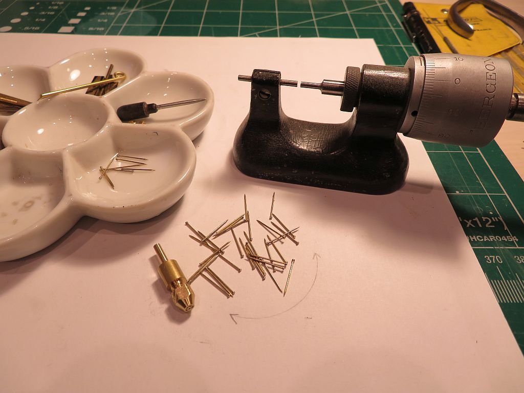
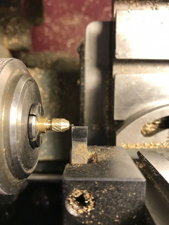
 Thanks to all for your complimentary comments and for the additional info on the dorade vents. When i made the first set of "screws" for attaching the vents to the side of the cabin I used a commercial pin vice that is the traditional one that allows very small diameters down to basically 0 the way it works is a bit hit and miss being a shaft with a couple of cross cuts. This took a few tries each time to get the pin properly centered. I also used a file to reduce the diameter of the pin head and basically did the work by eye. Knowing that when they were assembled in the vents the slight variations in diameter would become obvious. So I decided to make a small pin chuck specifically for these pins. I used a bit of 1/4 inch brass rod and using the collet chuck on the lathe turned down the shaft to fit the new micro drill which is 3/32. Keeping some of the shaft at the 1/4 inch in order to thread the opposite end for the locking collar. This was then reduced and threaded 8x36. The threaded end was then tapered about 1/8 so that the locking nut could work to clamp the threaded end. The threaded end was drilled with a hole the same diameter as the pin to a depth of 5/32 then slit lengthwise with a .010" slitting blade. The shaft end was drilled to the pin hole with a #50 drill as a relief and to allow the pin end to close. First picture shows the chuck with the locking nut off. the lock nut was easier to work with the flats filed which allowed a wrench to tighten it instead of my finger and thumb (which got cut on the sharp edges hence the flats) The cross cut is more visible in the next picture. I cut enough pins to complete both sides. By using the collet chuck and the new pin vice it enables me to complete a single operation on all the pins knowing that they will be concentric for the next operation. The pins stayed concentric in the new chuck. The heads were turned down to .93mm which turns out to be just under 5/16 actually closer to 19/64ths in diameter which is very close to the diameter of a #8 round head wood screw at 1:1 The next operation I will shape the round and then slot them using a different pin vice and a block of wood to position the jewelers saw blade as in the next picture. I will set up the boxes with a slot on the bottom and by bringing the vents up it looks better than having them cross the panel reveal. That's all for now. Michael
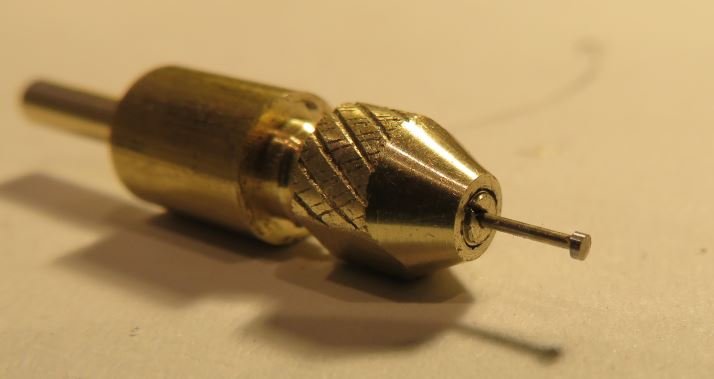

-
Eberhard and Kurt, thanks for posting those pictures. That watchmakers staking tool caused me to drool a little.😉 Michael
-
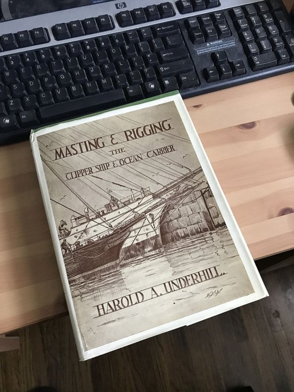
This should give me some Ideas. l received this in the post today. I know I only have one mast but this will expand my knowledge. Michael
-
Very nice Johann, Does the carriage with the spool need to be moved by hand or does the threading pull it along as it winds? I solved this by using a slightly springy brass plate that put just enough tension on the spool but let it get pulled along. here is the link to the serving machine that I did, it went through a number of improvements as I looked at Alex"s machine which is also great. I of course enjoy building my own tools as well. I really like the way you have supported the rope being served, and also beautiful Drawings. I thought about using a lead screw to move the carriage similar to the leadscrew on a lathe, My eventual feeling was that the thread pitch on the leadscrew would need to be the same as the thread that was being wound on the rope. At that point i decided to keep it simple, by using the action of the serving thread to pull along the spool. Regards Michael
-
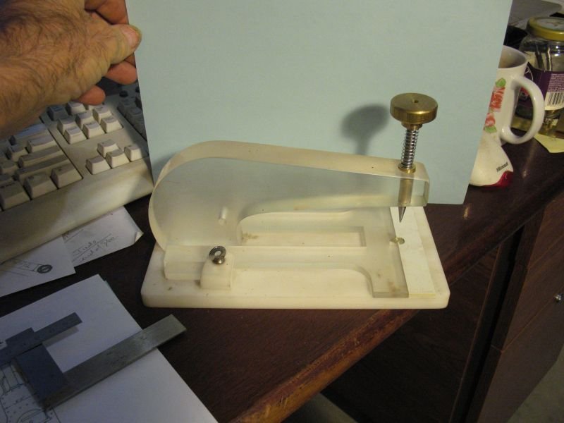
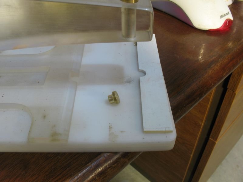
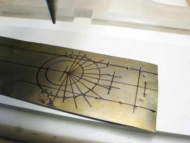
Here is a simple riveting tool I made to punch small rivet impressions in metal or styrene. the punches are made from 1/4 inch drill rod with brass anvils quite complex layouts ate possible by using a marked layout or very straight sets using the fence One of the ways in which the spacing of the rivets is accomplished is by setting the anvil up in such a way that there is a set distance from the recess in the anvil and the edge the punched rivet then is registered against the edge before the next rivet is punched. The Anvils are made of brass and the depression is done with a hardened punch made from the 1/4 inch drill rod. These are all nominal dimensions of course because any combination of nominal sizes will suffice. A fine ball point pen works well also in soft brass or copper. The hardwood dowel would only be useful for a short few rivets a harder anvil of brass or steel would be much better. Wefalk mentioned in Eric's Arabia thread "Somewhere on a railway modeling site I saw someone putting a second hole into the anvil at a distance required between two rivets. This acts as a register for making the distances between rivets equal. Thin copper, brass, or aluminum sheet can be used as well, but then I would make the anvil from brass or steel, with holes drilled of the rivet diameter." Perhaps there are some other great Ideas regarding this subject that would be helpful. Michael
-
So as not to hijack Eric's thread I made a more substantial riveting tool but it is also in another thread so I will start a thread about this subject. Michael
- 599 replies
-
- 4
-

-
- sidewheeler
- arabia
- (and 4 more)
-
My drill to mill adapter
michael mott replied to steamschooner's topic in Modeling tools and Workshop Equipment
Hello steamschooner An interesting adaption One thing that is important to remember is that a drill chuck that is attached with a morse taper is not a safe option for using sideways pressure on a bit. If the chuck is screwed on it is not so much an issue with small cutters and soft materials, or if there is a capture screw that is inside the chuck securing it to the mandrel if it is a morse taper type. I have seen a chuck come off used this way. Be safe. Michael -
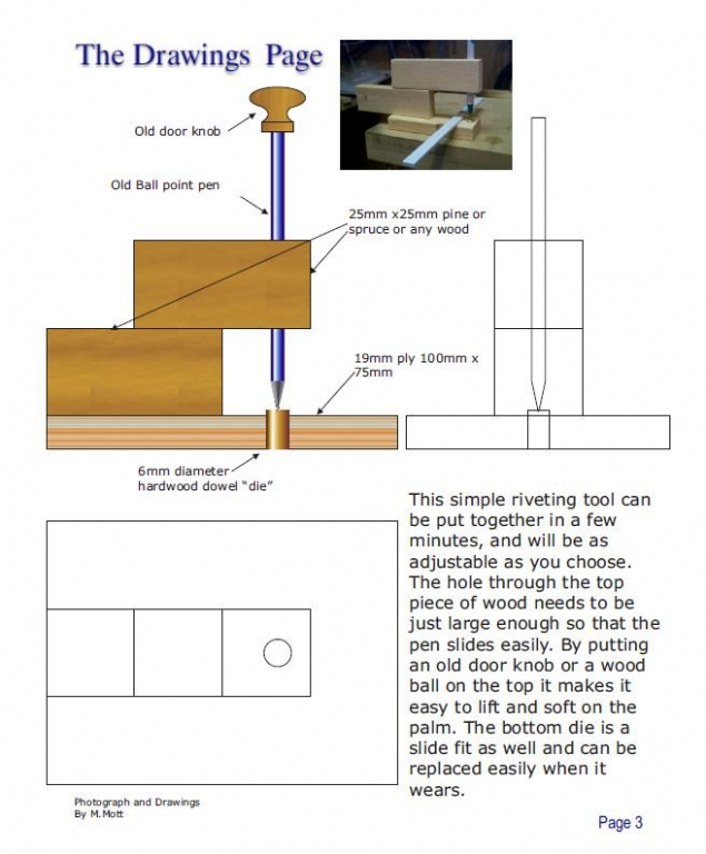
Looking good Eric! Styrene is such an adaptable material. an old ball point also works well for riveting simulation in thin styrene. I pulled this from a small magazine I did for Gn15 forum (a model train site) many years ago. Michael

- 599 replies
-
- 11
-
-
- sidewheeler
- arabia
- (and 4 more)
-
Mark Ah I see you are adept at adding material to your scrap box just like I am. It is amazing how these bits get used up over time. Michael
-
Another way to make shackles
michael mott replied to vaddoc's topic in Metal Work, Soldering and Metal Fittings
Hi Vaddoc look like you are well on your way and as you say the more you make the more uniform your shackles will be, and in any case they come in a wide range of sizes so you will be able to group them as they accumulate. I have noticed that the copper is a little easier to form when it is annealed if you can use the vice to squash the ends flat you might find it a little easier to control just how much flattening you want. you could tape a steel washer to act as a stop so that you don't squash them too much. Just some thought to add to the great job you are doing. Michael -
Mark great solution, it is always great to see how others solve how to do something with alternative tooling. Happy new year to you and your family. Michael
-
Hello Mark, following Druxey's comment about dusting the inside of the mold with talc first, I totally agree, once dusted however make sure to bang the open faces of the mold on the table before closing it. this will remove any loose particles of talc. I say this after casting thousands of pieces of jewelry in pewter and white metal in centrifugal vulcanized molds when I was a young man. Beautiful work on the turning. and I agree with Greg's comment about the view out your window as well A happy new year to you and your Family Michael
-
Exquisite workmanship Michel Thank you for sharing it with us. Michael
-
Hello Kevin, welcome from the northern part of the continent. Michael
-
I always find your thoughts and work to be very inspiring Gerald. A happy and prosperous new year to you and your family. Michael
- 281 replies
-
- 3
-
-
- falls of clyde
- tanker
- (and 2 more)
-
HMS VICTORY 1765 by albert - 1/48
michael mott replied to albert's topic in - Build logs for subjects built 1751 - 1800
A happy new year to you as well Albert. Michael -
Great looking Workshop Antony, also nice progress on the model. A happy and prosperous new year to you and your family. Michael
-
Congratulations Dave, I have to agree I would not have guessed that this model was carved from a block of wood, nicely Done! Happy new year to you and your family Michael
-
Cutty Sark by NenadM
michael mott replied to NenadM's topic in - Build logs for subjects built 1851 - 1900
Nice re-purposing of material Nenad a complex little piece looks like you have it well under way. A happy and prosperous new year to you and your Family. Michael- 4,152 replies
-
- 5
-
-
- cutty sark
- tehnodidakta
- (and 1 more)
-
Rob this seems counter intuitive. Is this a scaling of Nature issue, similar to the fact that one cannot make scale tubes in a model steam boiler because you cannot scale steam. and in the case of the sails we cannot scale the stretch of the canvas in the non wind? And a happy new year to you and your family. Michael
- 1,208 replies
-
- 3
-
-
- great republic
- clipper
- (and 1 more)
-
Beautiful work on the Chair Doris! I am guessing that you have more than 24 hours in your days. A happy and prosperous new year to you and your husband Doris. Michael
- 1,035 replies
-
- 7
-
-
- royal katherine
- ship of the line
- (and 1 more)
-
I hear you! Good to see that you are still getting work done Dave, in the end it is my opinion that it really does not matter on what one works so long as the reason for doing it, is to bring you peace of mind (isn't that why we work at hobbies). Have fun in the new year. Michael
- 742 replies
-
- 5
-
-
- constitution
- frigate
- (and 1 more)
-
Daniel, That is some superb precision fitting those stringers, (I think that is the correct term). Michael