


michael mott
-
Posts
5,200 -
Joined
-
Last visited
Content Type
Profiles
Forums
Gallery
Events
Everything posted by michael mott
-
 Great to hear the health issue is behind you Danny,I look forward to seeing how you proceed with this kit. I spent hours as a kid looking at similar vehicles in the Science Museum when it had large volumes of models on display. Michael
 -
Greg I had the same problem with the backlash on the big mill drill, it is why i fitted the dial verniers backlash is no longer an issue because the dial does not move until the carriage moves so the information about the position of the table/vise is always the same when you follow the dials. Michael
-
Micro Drill Press
michael mott replied to michael mott's topic in Modeling tools and Workshop Equipment
Thanks everyone for the compliments. Keith the large mill drill is out in the shop and the motor on it is 3/4 horse, as i mentioned the poor mans DRO is accomplished with three butchered dial vernier calipers. The sensitivity is quite a way from the smaller drill inasmuch as the quill on the big mill drill is 3 inches in diameter and the handles are about 12 inches for a radius of 24. which means that when using it to drill tiny holes I need to be able to view the work through a magnifying visor while stretching my arm up to the handle to make very fine pecks at the surface. I am comfortable doing a lot of work with the big mill drill. The small drill is very quiet and I can get close without feeling like I am doing Yoga stretches to operate it when drilling. I guess the best analogy is the difference between cutting some brass with the jewelers saw versus the 20 in bandsaw, not that I don't use both for the appropriate tasks. I hope that I have clarified why I made this tool. Today another tweak to smooth out the operation I flipped the quill dial over so that it read the proper direction when going down It look a bit tidier as well. Also made a small keeper plate for the dial end of the x direction for the table so that the end of the dial does not get caught in the T slots and made another collet out of brass for the 1/8th shanks bits it now runs very true. Michael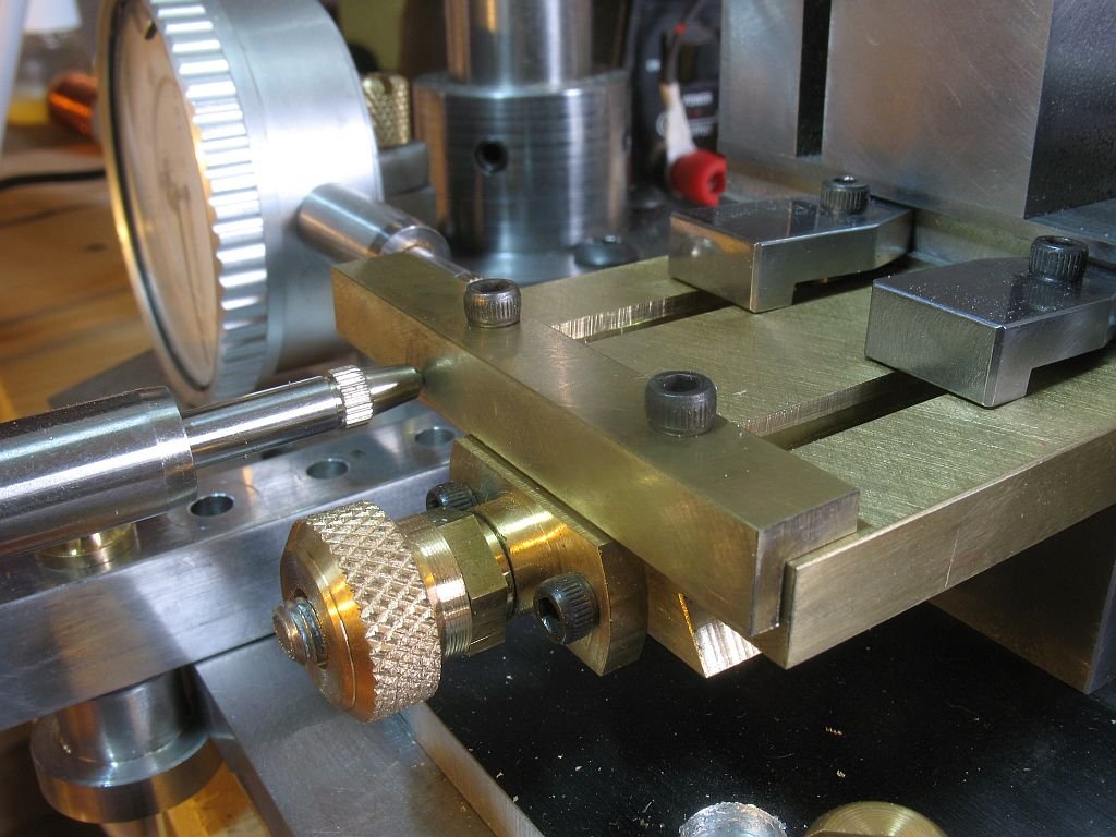
- 56 replies
-
- 12
-

-
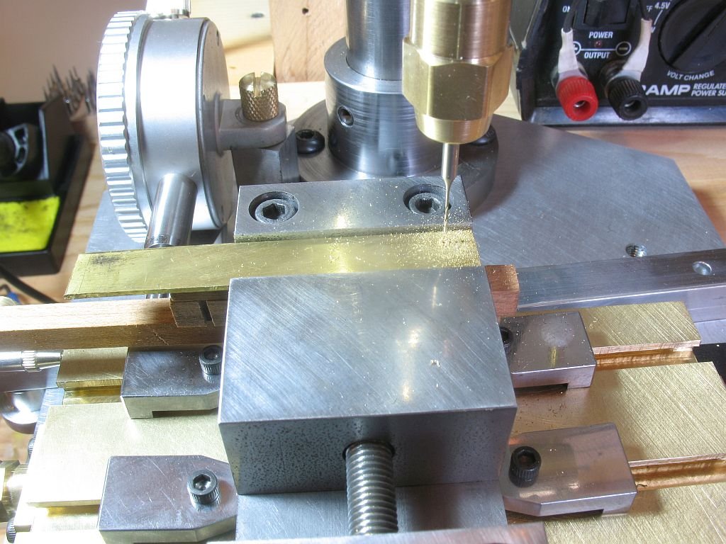
Riccardo yes you must. Keith It is hard to keep coming up with something original and constructive to say. So if I am understanding the sequence correctly the little metal keeper plates were primarily for drilling the holes for the brass rods that protruded through the brass crosspieces. You really are doing an outstanding job on this model. Michael
-
Micro Drill Press
michael mott replied to michael mott's topic in Modeling tools and Workshop Equipment
Joe that is too funny, basically I made this from stuff I had laying around in my scrap and material stock I had to purchase the dials ans the 3/4 hard aluminum plate for the base. Making something like this for sale would be a whole different ballgame. I would have to do a complete review of design considerations, source components like motors gears bearings. I am not sure anyone would want to spend the sort of dollars need to make this a viable option. Bespoke tooling is an exciting idea. One of the things I enjoyed about custom modelwork when i was working full time at it was that basically it was a labour intensive job and low cost on materials, the projects were expensive and I was well paid for them back in the late 70's I was charging $50 per hour shop time and getting it Quite a few of the architectural models were $25,000 -35,000 and took 3 to four months for a few guys. I worked of a fixed price and was sometimes caught short and the shop rate diminished accordingly. I look at the prices of the model machine tools that are on the market and I know that I would not be able to compete price-wise. As you know this tool evolved from a personal need to not have to use my big mill for very small work. A viable tool that I would be willing to sell would need considerable refinements and although would be that same sort of size would be cleaner regarding some of the design elements. It would have to be an individual and negotiated endevour. I need a nap! Michael -
Miniature Russian carving tools
michael mott replied to druxey's topic in Modeling tools and Workshop Equipment
Wow thanks for sharing the pictures vossiewulf. Druxey those do look rather tempting congratulations on your acquisition. Michael -
Micro Drill Press
michael mott replied to michael mott's topic in Modeling tools and Workshop Equipment
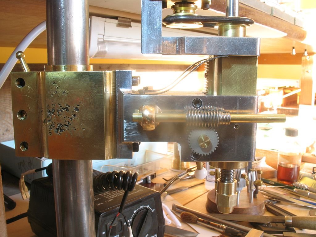
Greg Thanks you are too kind, But I have to admit looking at Gerald Wingrove's tooling was my inspiration. it still blows me away that he made all those machines design build in 9 weeks. I couldn't wait to go to town so stole the 1/2 inch travel dial of my magnetic base. Since the quill doesn't really need to travel any further than that before adjusting the whole thing on the pillar anyway it seemed like a good idea. I found a reject toolmakers clamp part and butchered it some more to make a tab for the dial to mate against. I had an odd bit of aluminum that was already bored 1 inch with a set screw so substituted the steel one for a brass thumbscrew to make adjusting it easy. So now it is good to go . Michael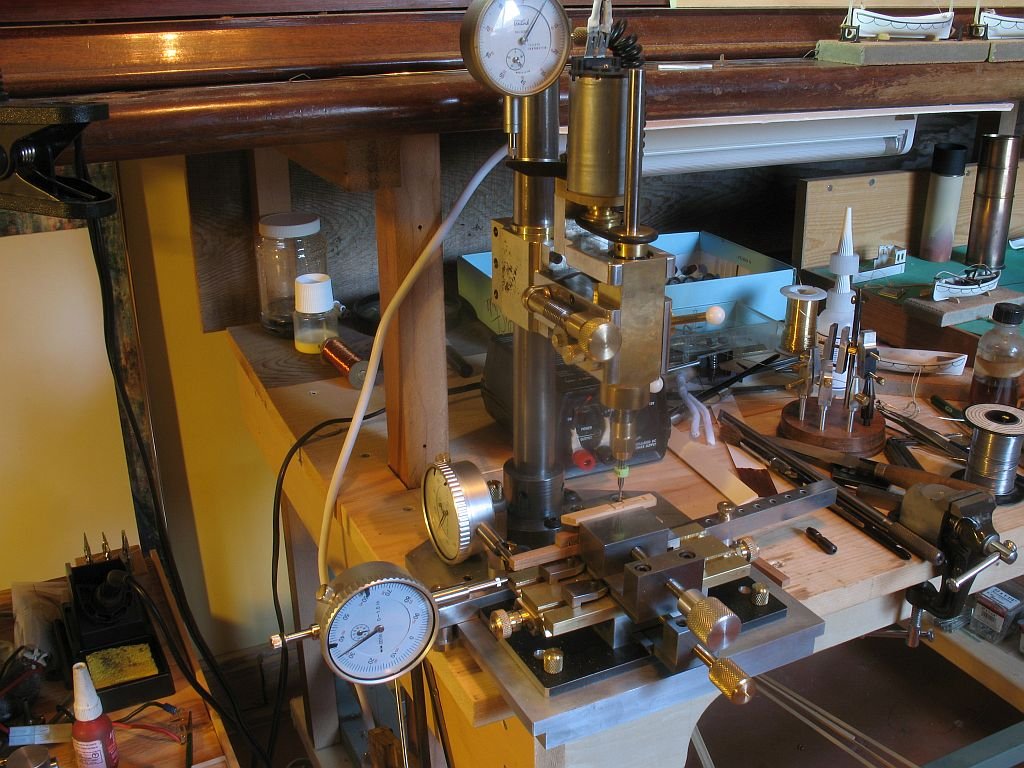
-
Micro Drill Press
michael mott replied to michael mott's topic in Modeling tools and Workshop Equipment
Riccardo thanks, the quill control is now sorted and the thumb-wheel works a treat. and raised a little Next up another dial, which will have to wait until I head into town again. So Mike yes it is now a micro Mill/Drill. Michael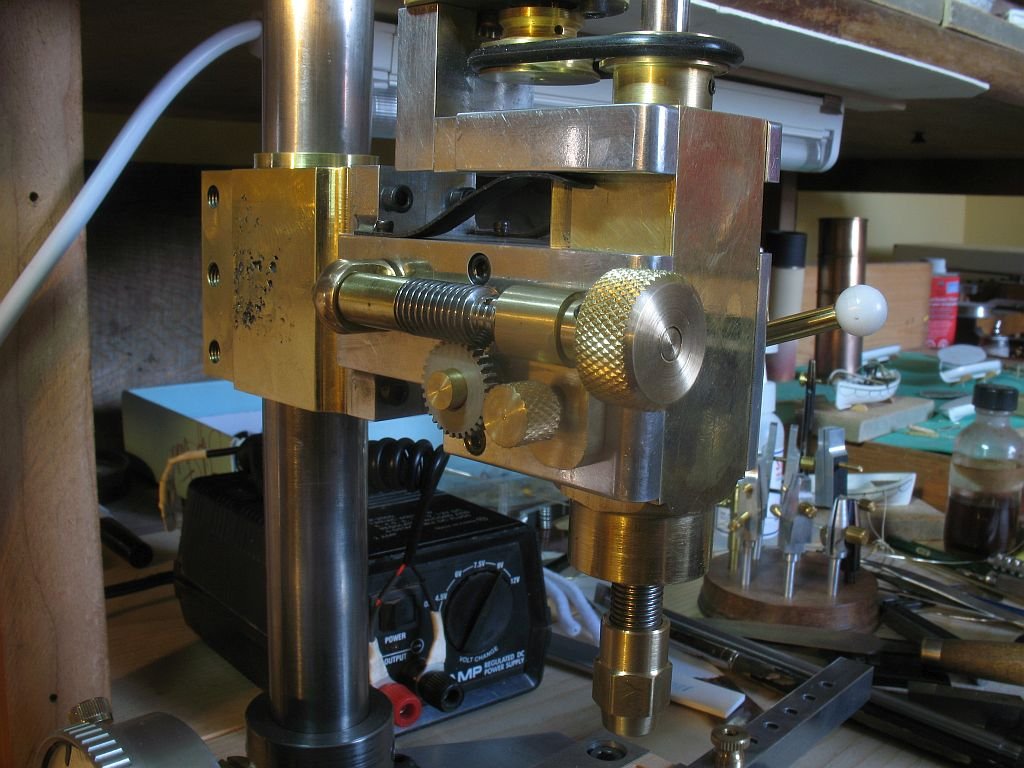
-
Hello Ed Seeing your picture of the parceling reminded me of the work by Longridge and Have just spent an hour looking for my book and I am not happy that I cannot find it. Beautiful work on the masts and shrouds, I think Longridge would be tipping his hat to your skill and Craftsmanship and asking to come and visit your shop. Michael
- 3,618 replies
-
- 4
-
-
- young america
- clipper
- (and 1 more)
-
Micro Drill Press
michael mott replied to michael mott's topic in Modeling tools and Workshop Equipment
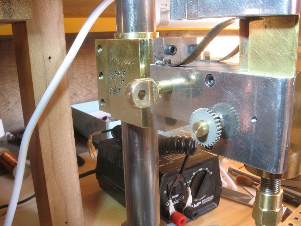
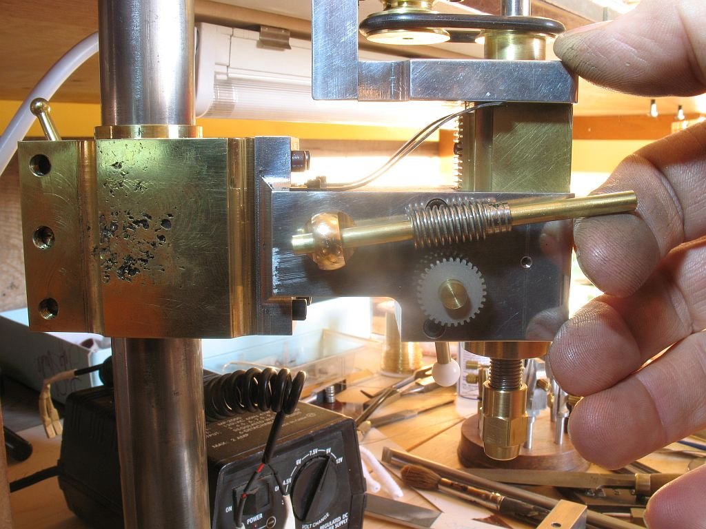
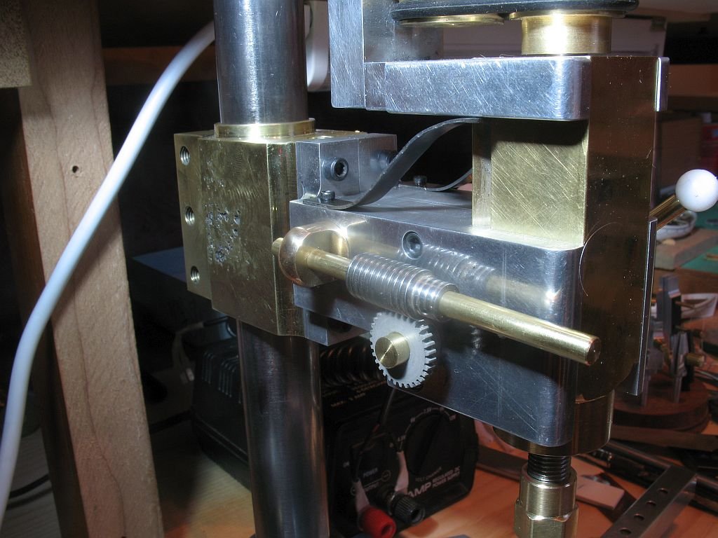
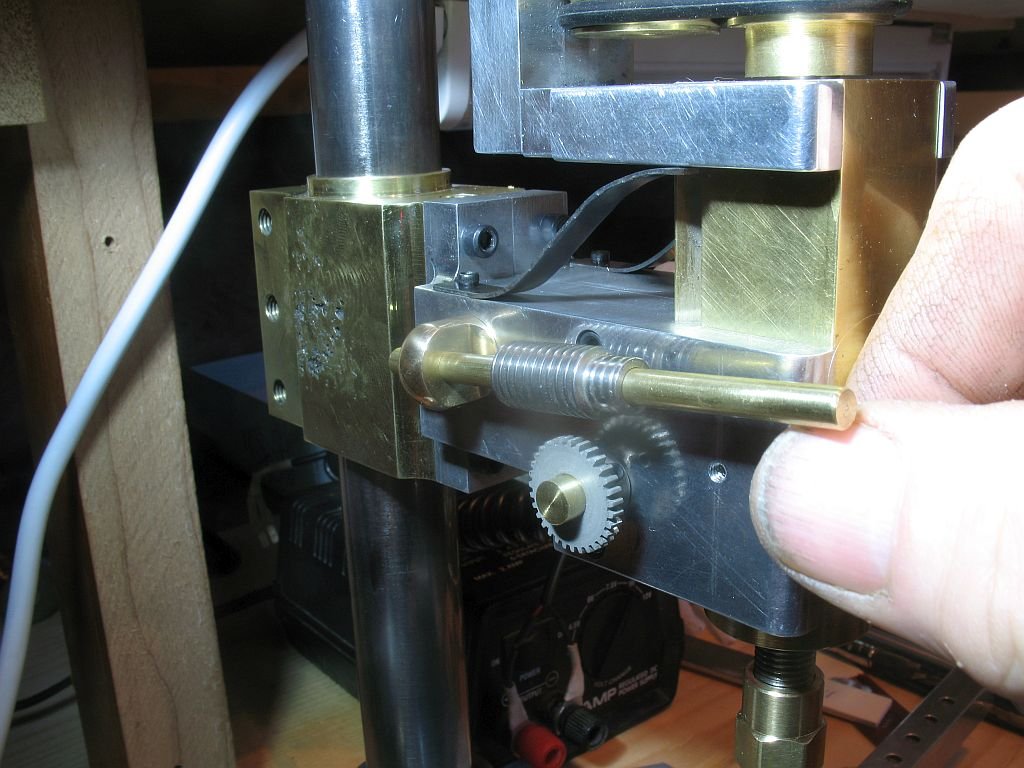
Fixed a new piece of 1/4 inch with a 1/8th hole offset.055" pivot end turned down to .125" then parted off the original shaft slipped into hole, it will get fixed with some locktite. now it is parallel in the engaged position just need to make the locking carrier for the finger control end and a couple of stop collars at the pivot. Michael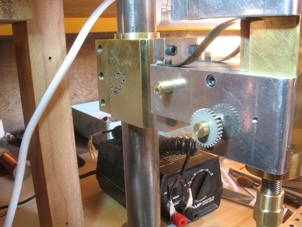
- 56 replies
-
- 12
-
-
Micro Drill Press
michael mott replied to michael mott's topic in Modeling tools and Workshop Equipment
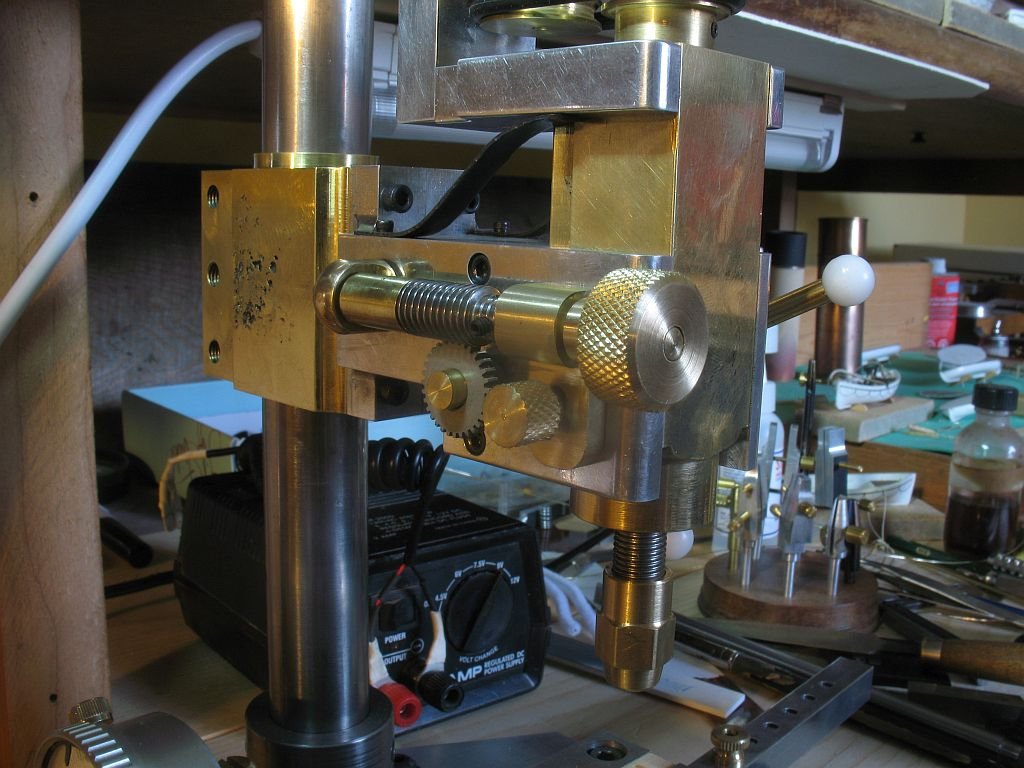
Jaager very true, but because i have a large mill drill that can do all that I need regarding the big stuff after all I used it to build this micro drill/mill. I should have the quill adjusting control finished by the end of the day. I copied the same mechanism that is used on my large mill pretty simple the toughest part was rooting through the gear scrap box to find a matching worm and gear. One minor irritation is that I followed the drawings I have been doing and the pivoting holder at the pillar end is a little too high because I had lowered the quill gear by .055" for some reason while doing that work but did not update the drawing so the shaft is not parallel to the horizontal when engaged. An easy enough fix it means having to cut the shaft of the pivot and shifting it by .055 vertically an re attaching it. so that the shaft is then offset from the centre. I had thought about turning a new one with the shaft offset, but cutting it off and resetting it is easier and since there is not a lot of strain on the part it makes sense rather than making a whole new piece. Michael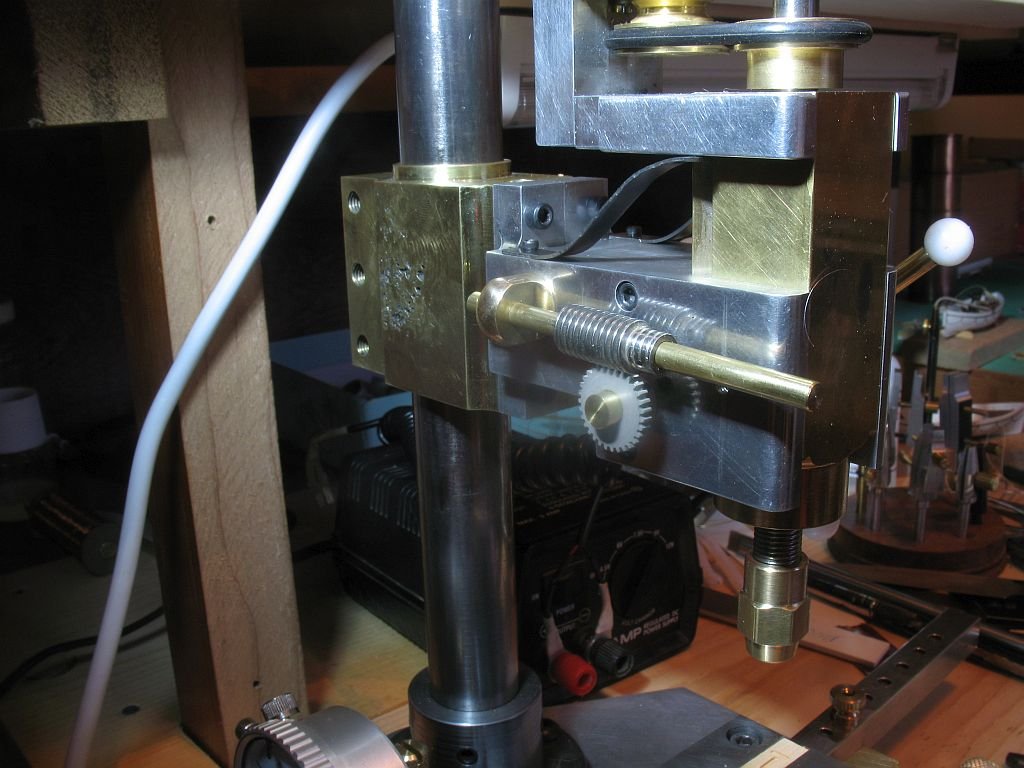
- 56 replies
-
- 12
-
-
Micro Drill Press
michael mott replied to michael mott's topic in Modeling tools and Workshop Equipment
Oh Keith, I love the digital age as well.... where would photography be if we were still using developer trays... and the camera technology is amazing. I just like seeing the whole day on the clock face, I can look at it and know that there is about enough of the day left to get this done . 6:35pm just doesn't convey the sense of the day to me, same with the dials. Off to add a little tweak to the quill. Michael -
Micro Drill Press
michael mott replied to michael mott's topic in Modeling tools and Workshop Equipment
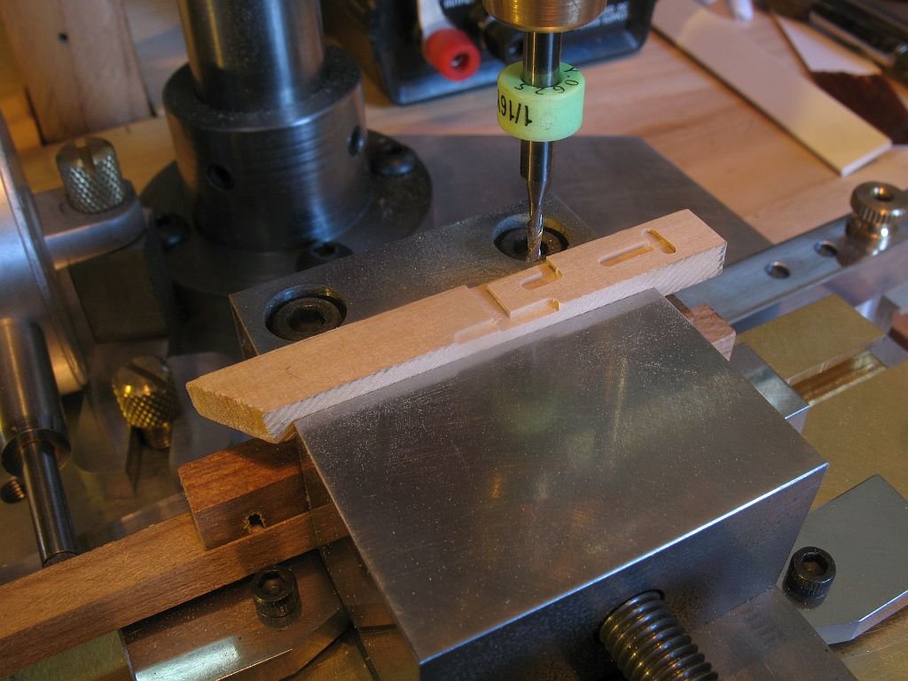
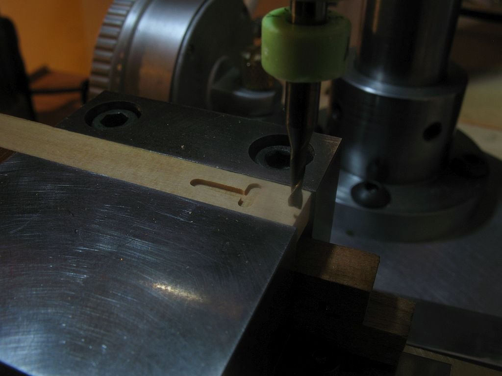
Hi Keith I have one digital caliper and do not like it, I guess I am just an old analog guy, that said I do have three dial calipers fitted to my mill in the shop a cheap man's DRO Of course I had to try the milling thing on it and immediately discovered that I do not have any means of locking the quill down nor do I have it set up to measure the depth. (I see another dial in the works) I did at first made a swipe on the brass it worked but I did not want to go any further because of the aforementioned issue. So a 1/4 inch scrap of Castello Boxwood was substituted...... I can see that I am going to have to make a couple of modifications to the quill control. This is encouraging because I had not thought about it as a mill drill, only a drill. Michael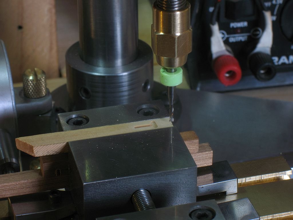
-
Micro Drill Press
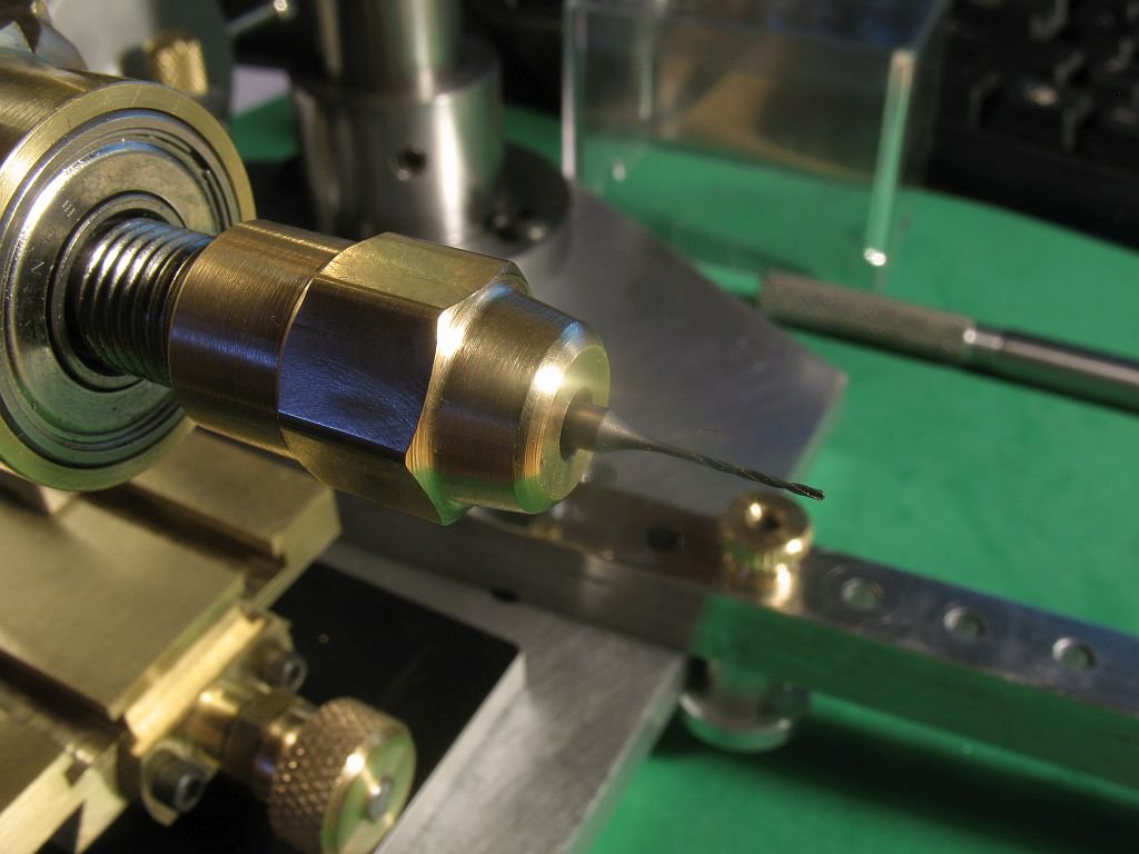
michael mott replied to michael mott's topic in Modeling tools and Workshop Equipment
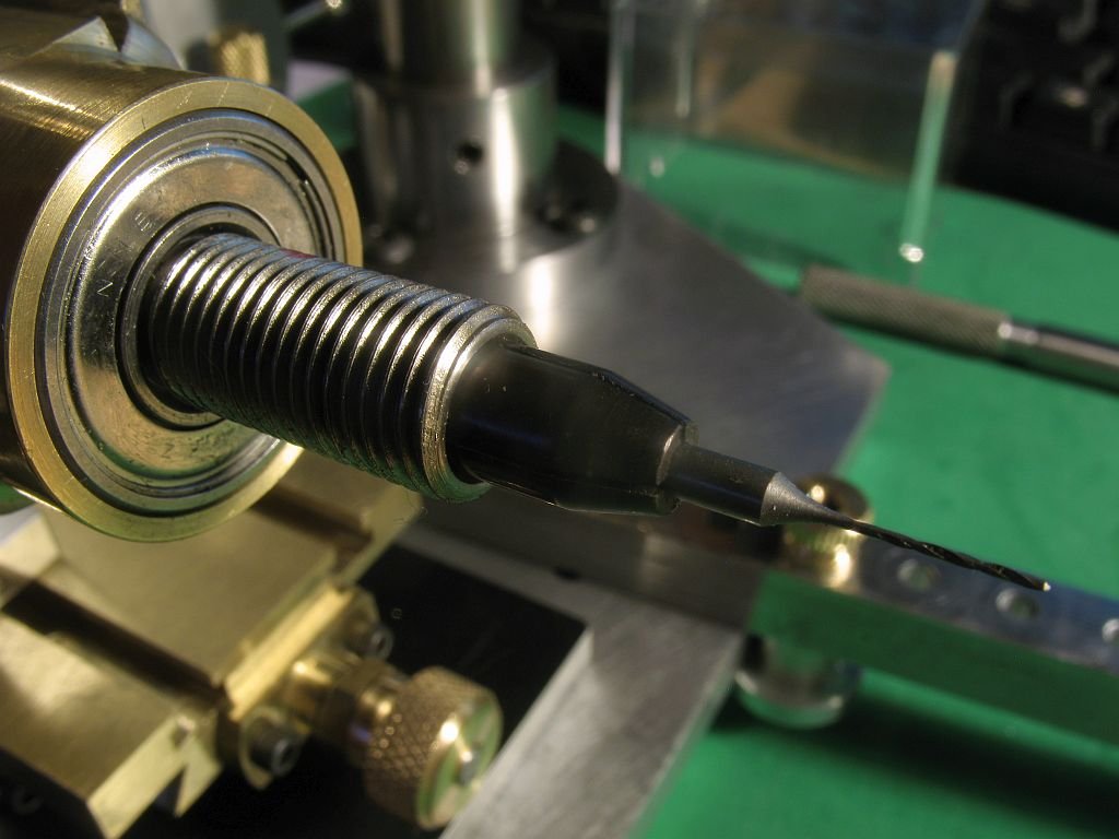
Bob thanks Mike yes it really is only a drill press, I would have done a few things differently if it were going to be a mill, now that you mention it maybe down the road I might make a small mill. Jack thanks I just finished the 1/8th collet and set to drilling with the #80 drill bit the smallest I have 2 holes .040" apart The first attempt i was a bit too aggressive with the feed down and broke the drill in the hole.... could have been a faulty bit........ The second bit worked well and I was much more gentle with the feed. The thing I like the most about this drill is that I can barely hear it. I probably wont be drilling too many #80 holes but it is good to know that the drill can handle it. Michael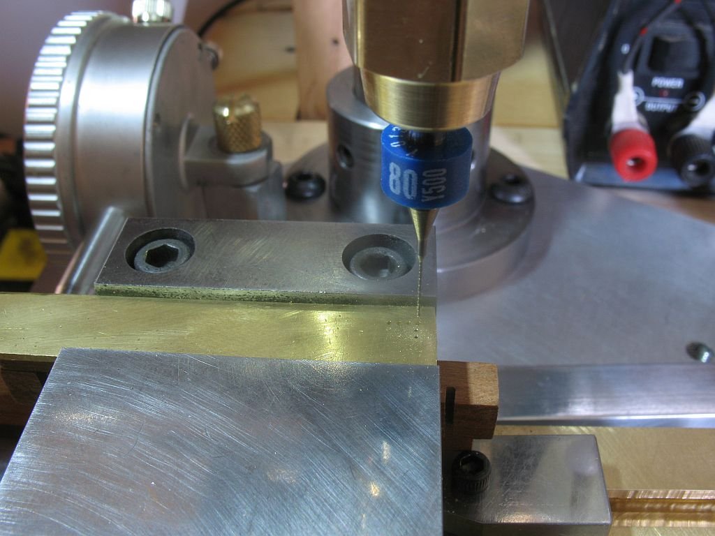
- 56 replies
-
- 11
-
-
Micro Drill Press
michael mott replied to michael mott's topic in Modeling tools and Workshop Equipment
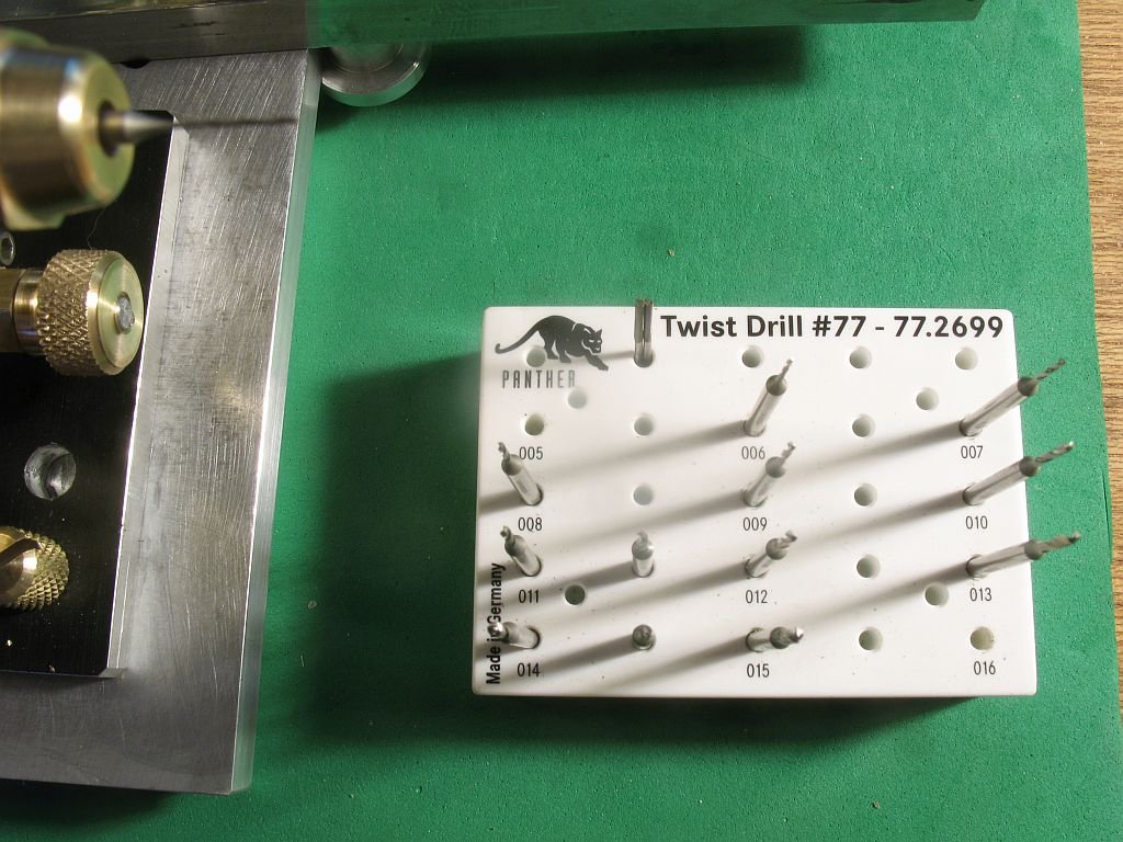
Thanks Druxey, I did quick test with the .05mm drill (.019") which is still pretty large as micro holes go but am pleased with the results in some .062" thick brass. 4 holes spaced .040" apart now to finish the 1/8th collet so i can test the #78 drill bits. Michael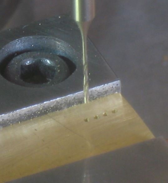
-
One other thought regarding the lifeboats is to use a drape form mould. Michael
- 2,625 replies
-
- 5
-
-
- kaiser wilhelm der grosse
- passenger steamer
- (and 1 more)
-
looks like is would function as a drip edge to direct water away from the glass. Look great so far Bob . Michael
-
Micro Drill Press
michael mott replied to michael mott's topic in Modeling tools and Workshop Equipment
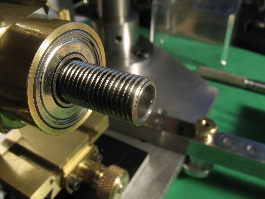
Thanks for the compliments Mark and Aviaamator Good morning Moxis. I like the machine that you have. Regarding the collets and chuck I generally find that collets are more accurate than 3 jaw chucks. The reason I built this small drill press was to overcome the issue that you describe. I began with the premise that very small drills come with one of two basic Shank Diameters this is using the imperial system which is common for me the 3mm and 2.35mm shanks are the metric equivalents. The quill shaft is turned from some 3/8 (10mm) drill rod or tool steel I used the 4 jaw chuck to ensure that the rod was concentric with the Lathe axis. the chuck end was threaded using the lathe cutting a 3/8 x 24 thread (common thread size for a lot of small drill chucks) then the end was drilled and reamed to 1/4 inch for about 1 inch to accept one of the two collets one being 3/32 and the other 1/8th The collets are turned from some 1/4 inch drill rod and the cross slit with the slitting saw with a .010" blade width. I made the collet to function in the same way that a Dremel collet works by being trapped at a dead end with the closing collar pinching down the conical section. The angle of the cone is 15 degrees I relieved the bottom end of the collets in order to give a little more spring to them. The collets were hardened and tempered for springs. The closing collar is made from some brass hex stock and threaded with a bottoming tap then the hole through the nose end was drilled out to .154" (#25drill) and them reamed with a cone reamer that was made to the same angle as the collet. I have the option of using the 3 jaw chuck but most likely will only be using the 2 collets. I have been able to drill with the smallest drill in this set through brass without any difficulty and the drills run true. as soon as I get the wiring harness finished i will be doing a lot more testing. I hope this answers your question. Michael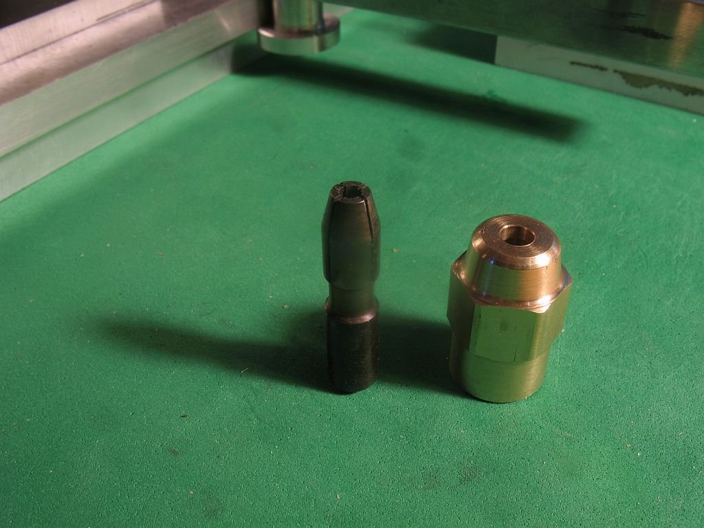
- 56 replies
-
- 12
-
-
Micro Drill Press
michael mott replied to michael mott's topic in Modeling tools and Workshop Equipment
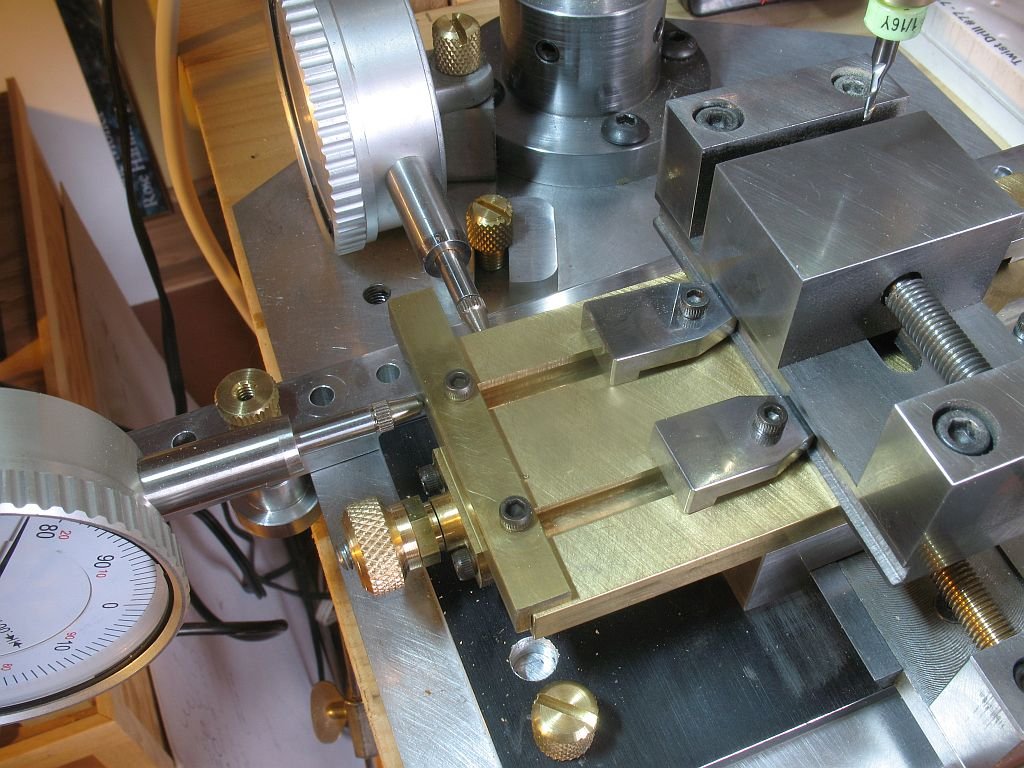
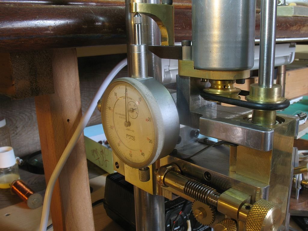
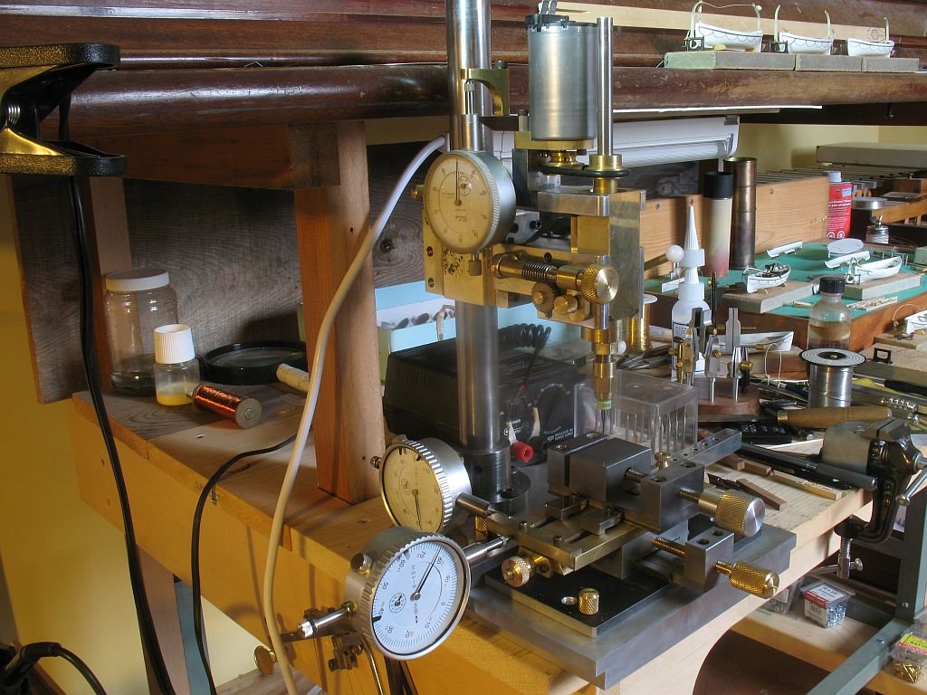
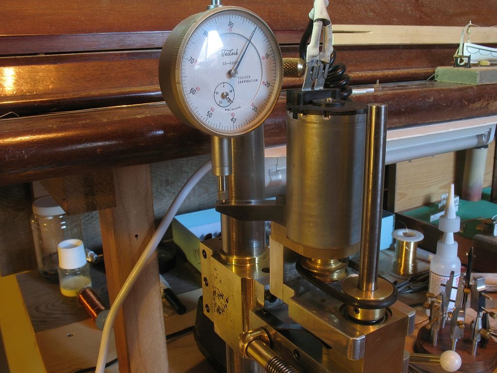
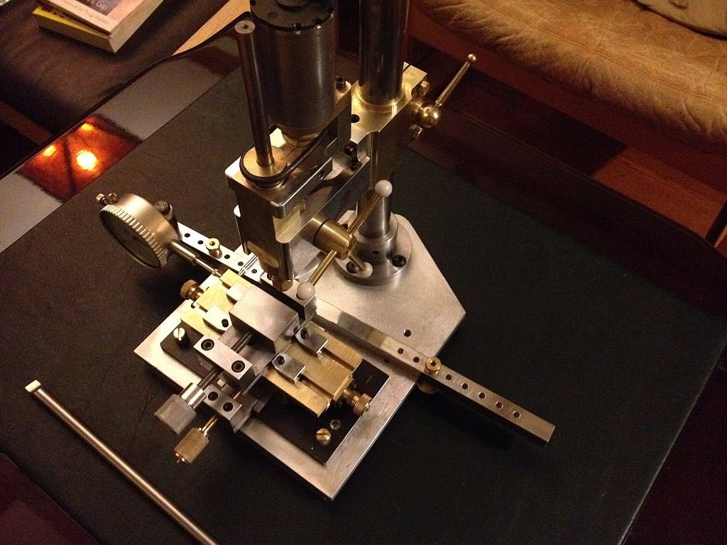
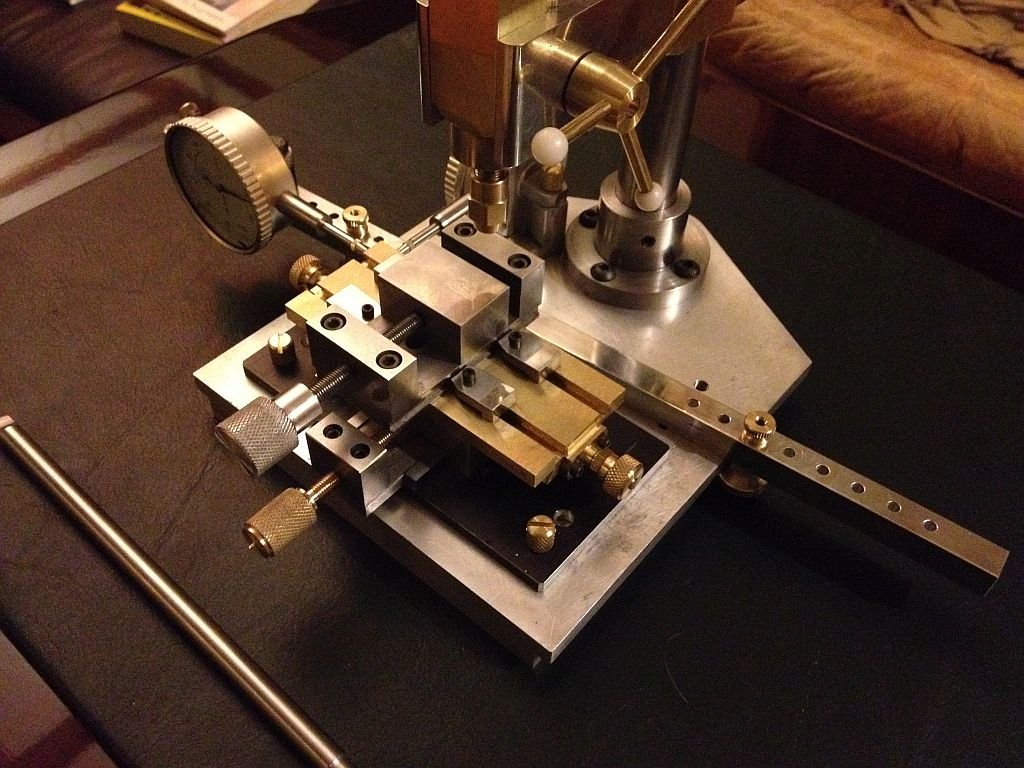
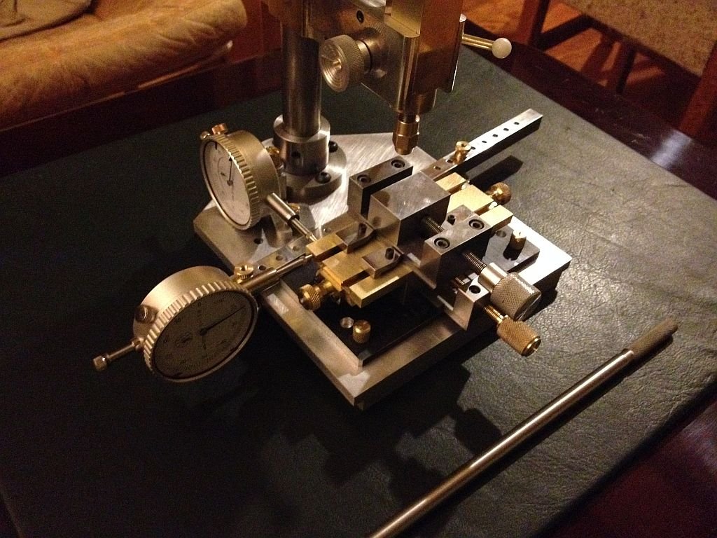
Hello everyone, thanks for the warm and encouraging remarks. The funny thing is that when I left school I started a tool-making apprenticeship but did not finish it for a number of reasons, not least of which the apprentices in the place I worked used us to do repetitive production work which was outside of the purview of learning, but served the management. So here I am 50+ years later making tools. I am happy building a few tools at a time the problem solving aspect of it keeps my mind active, and because all my tools are manual (no CNC) I find the concentration on each task sort of meditative and peaceful. I have been struggling with a rather nasty cold/flue bug this past two weeks so working has been hard to do, but I have to keep going. I have finished that main aspects of the micro drill and here are a few quick pictures of it. All that is left to do is to ad a small cable to the power tabs on the motor. I added a second leaf spring to the quill and it is much more responsive. The bar laying in front is a simple screwdriver that was an afterthought while trying to tighten the thumbscrews next to the pillar, so I slotted all of screws as well. The XY table was challenging to say the least. I had to make a T slot cutter in order to be able to clamp the vice or remove it and clamp work to the table. The XY table is held in place with the front brass thumbscrews and the holes in the base of the drill are spaced at 1 inch intervals front to back. There are things that will no doubt need some form of improvement, and I will find out about them as I use it. The trickiest part is being able to use the dial indicators instead of micrometer dials on the XY table. The front dial is attached to a 1/2 inch square bar that clamps to the base and is very adjustable, the rear dial less so. I will take some better pictures in the daylight tomorrow. Michael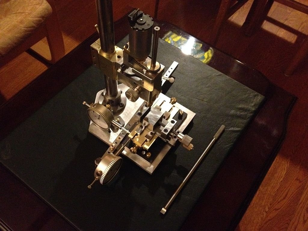
- 56 replies
-
- 16
-
-
Bob,Thanks for the link, it looks like a worthy project. I don't see any reason why with good hardwoods, and some quality threaded rod this would make a nice inexpensive tool that would be adequate for working with wood or plastic. Michael
- 13 replies
-
- 5
-
-
- dremel
- rotary tool
- (and 1 more)
-
Keith I must say that I enjoy seeing how you solve the manufacturing processes for the parts. The jigs that you devise are very interesting. Michael
-
Hi Nils, just catching up again things are looking like they are coming close to the finish, and it's looking great. Michael
- 2,625 replies
-
- 5
-
-
- kaiser wilhelm der grosse
- passenger steamer
- (and 1 more)
-
Hi Less this a similar jig to this one I designed a few years back. Michael
-
The nice thing about the .030" styrene is you can just hang it on a few pins which makes it very easy to remove. A word or caution regarding static, you would need to have some anti static solution similar to the wipes for large scree TV's. As Andy says a very inexpensive solution. Michael
- 3,618 replies
-
- 5
-
-
- young america
- clipper
- (and 1 more)
