Check out our new MSW Sponsor Innocraftsman
×


michael mott
-
Posts
5,195 -
Joined
-
Last visited
Content Type
Profiles
Forums
Gallery
Events
Everything posted by michael mott
-
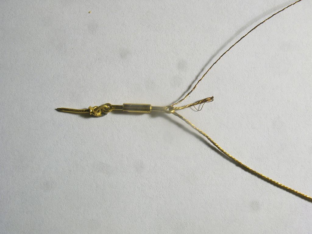
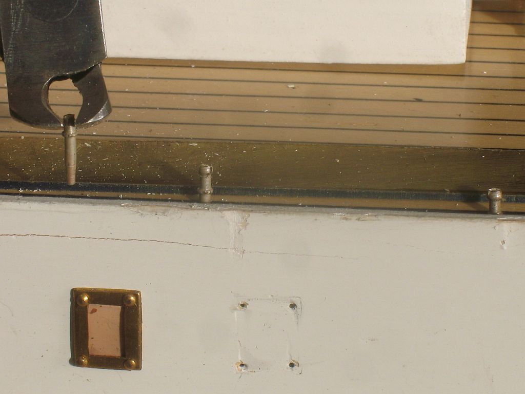
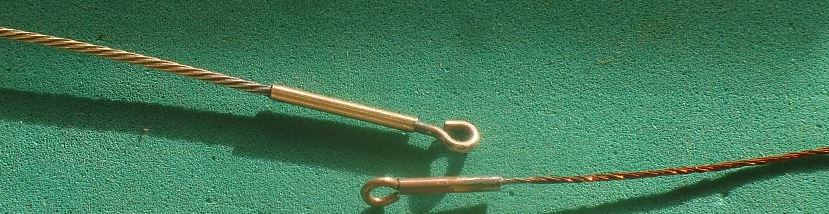
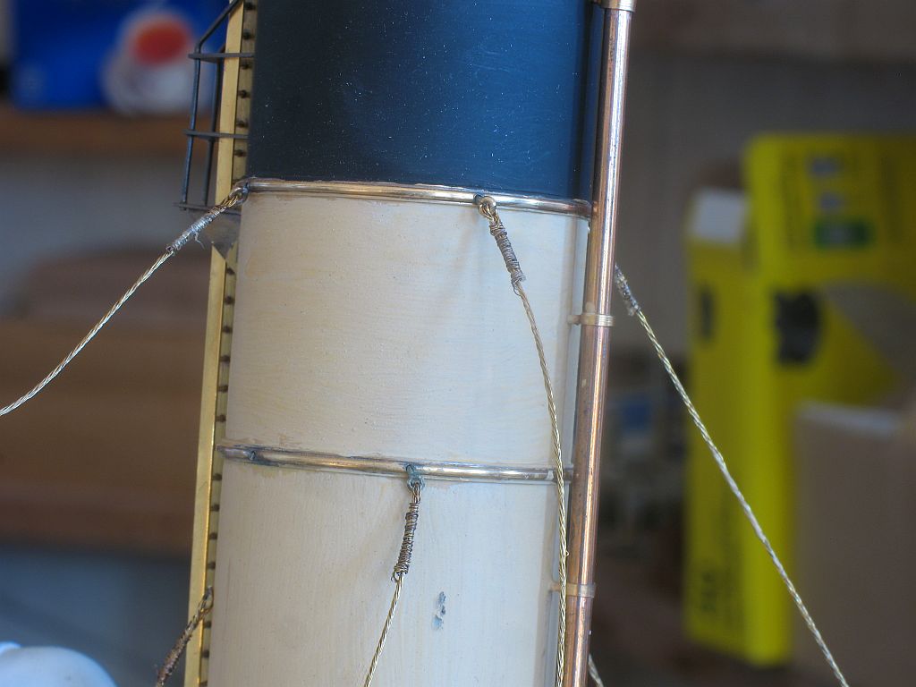
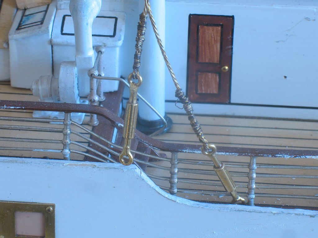
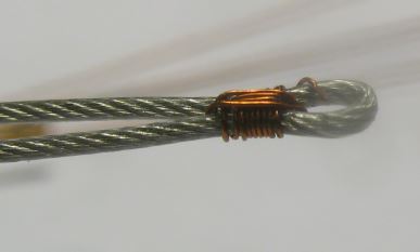
 Druxey, sad to say but the turnbuckles are fakes they look like some sort of forging or casting. I have figured out how they set them up, by unwinding one of them there are 4 strands of 3 wires and one set is left long and the other 3 are looped through the eye and then the long strand is wound round. I did a couple of tests with the fine copper wire by just twisting 12 strands then leaving just 1 strand long, I am confident that with a little practice I will be able to make the replacements I will look at tightening the loose ones in situ after I have mastered the method. The one on the turnbuckle is a rewind, and my first attempt not as pretty as I would like but I will get there. I am doing some practice runs and am getting ready to wind up some in the same manner as the originals I will look for some fine brass wire tomorrow. Druxey any thoughts on the potential cut? The only other way would be to remove all the upper deck which I am not going to do. Thanks for your support Joe Michael
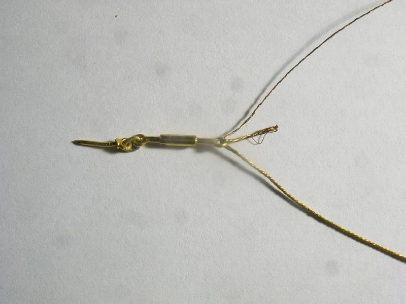
- 749 replies
-
- 13
-

-
- albertic
- ocean liner
- (and 2 more)
-
Congratulations Bob, must be a great feeling finishing up. Michael
- 348 replies
-
- 6
-
-
- pequot
- cable ship
- (and 1 more)
-
Thanks Mark. I just removed it I only installed it to use the bulk upload, Perhaps Admin will find a different solution than Flash 9. Michael
-
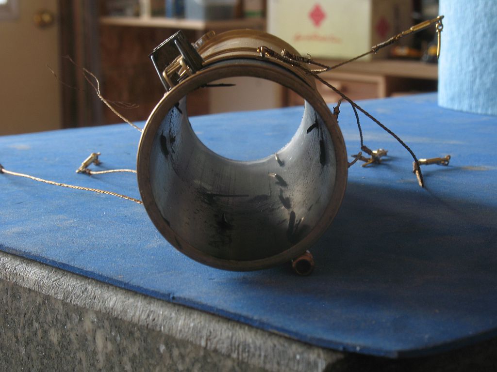
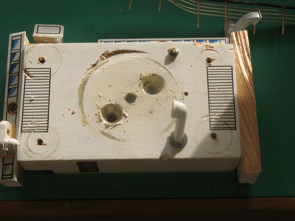
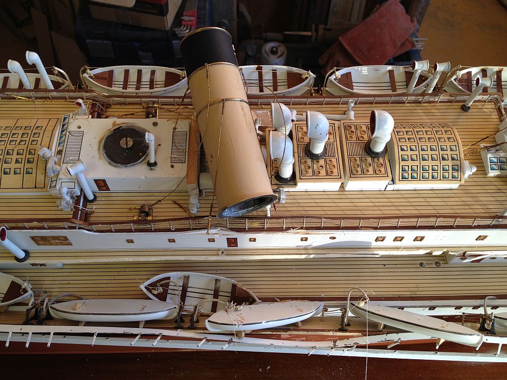
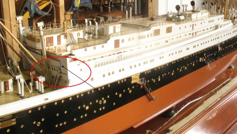
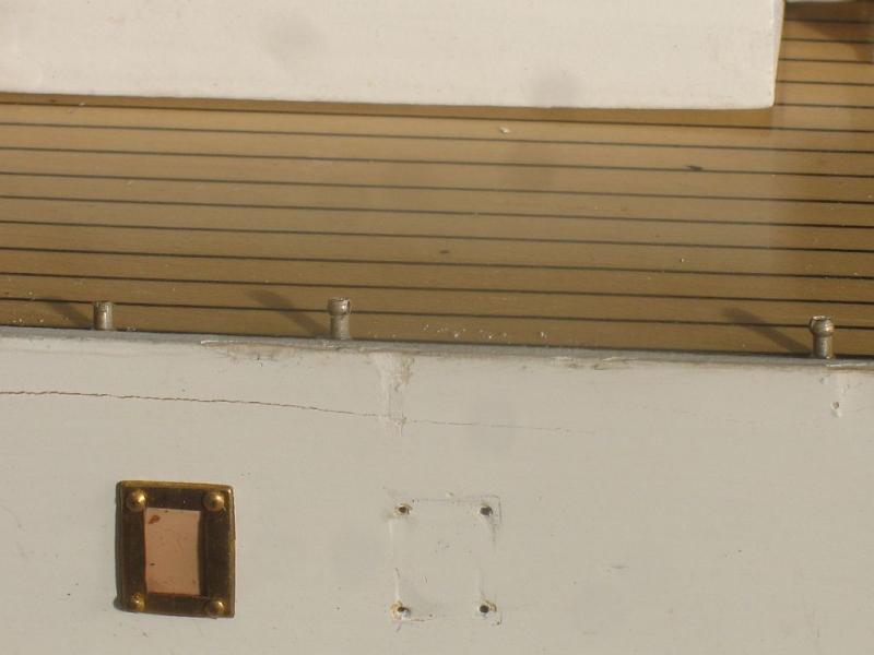
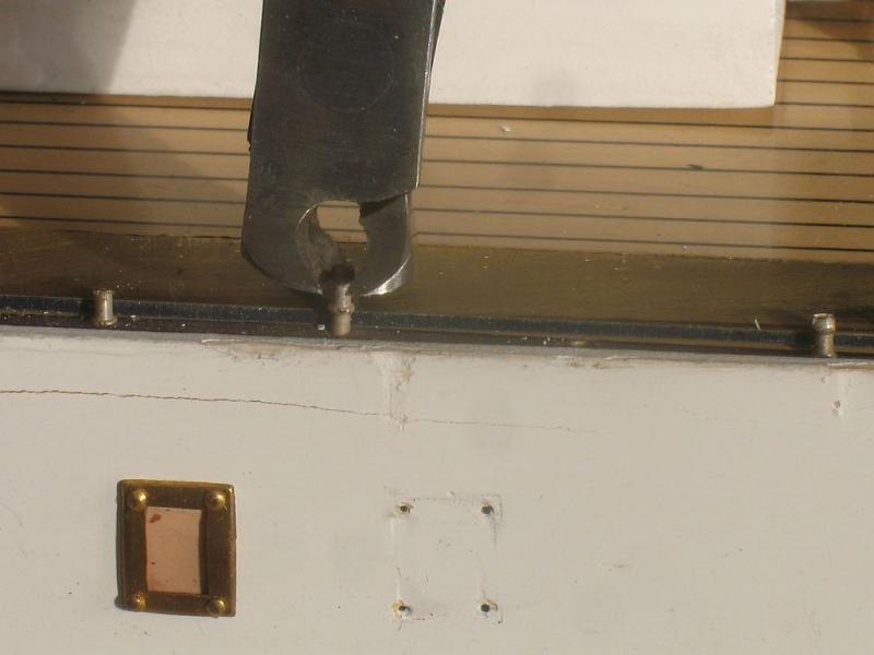
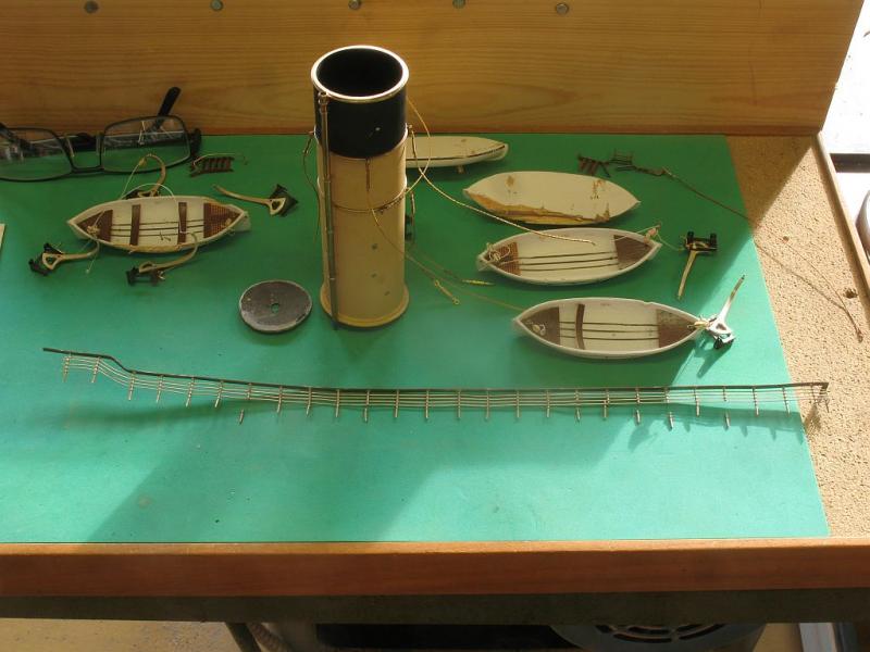
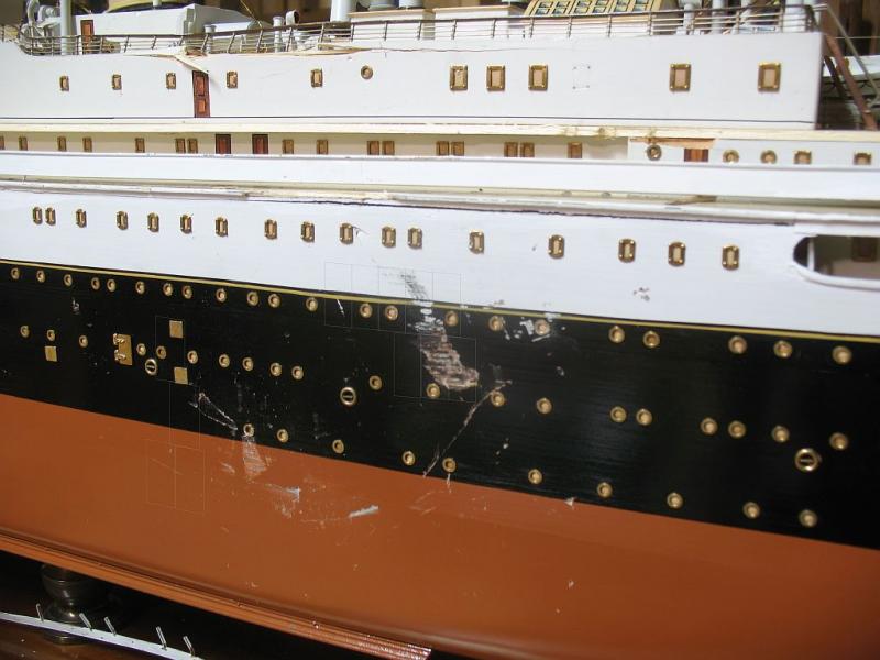
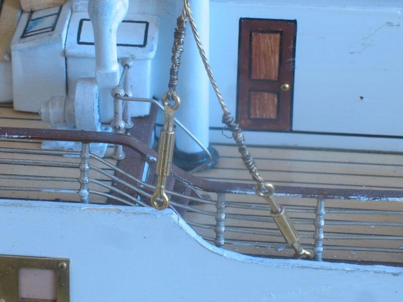
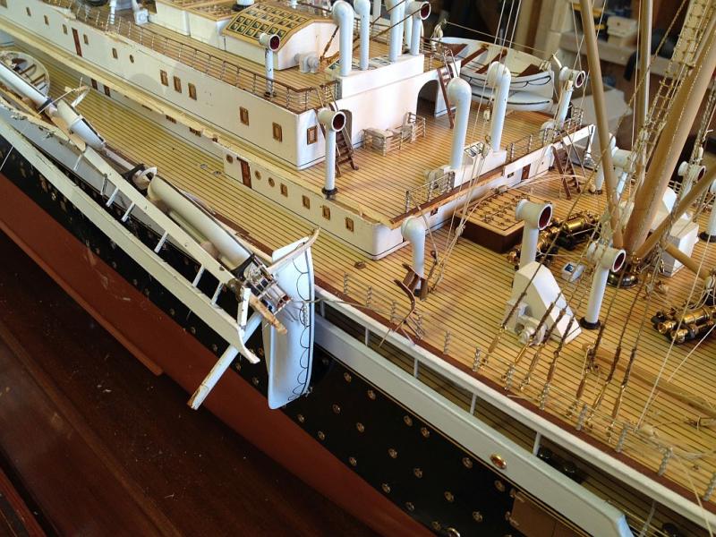
Yes, I do completely agree with you on this score. Jud you are right I do not want to replace all the wire standing rigging, but I might have to, a closer inspection shows that nearly all of the brass wire rigging is stretched and loose. One option is to undo then one at a time and then rewind them again and make a neater job of all of them. The other is to replace them all. All the funnel stays are all damaged to some extent, the eye-bolts that go into the funnel are bent wire and then bent down inside. Only a few of the running rigging lines that are fitted to the booms have been snapped and that will be tricky but likely easier to deal with that the wire rigging. I spent most of the afternoon removing the funnels and the structure under them the tops were crushed a bit. An area that is serious and not apparent in the beginning is the area highlighted in the next picture This one is troubling. Basically the whole of the front sheet is moved forward away from the deck behind it. This is the brass piece that the top member that supports the boat deck need to be soldered to after making a new piece. One thought is to cut the section at the blue line to remove the side in order to straighten and solder the new section to it. I am reminded of Druxey's comment now about hidden damage that was not apparent. I am having this feeling of digging a hole and it keeps getting bigger. Definitely stretching my abilities. I would love to have a time machine and go back to see how the chaps at Bassett Lowke assembled the metal rigging, did they have the metal stays pre-made on jigs, or did they wire them up in situ? better yet use the time machine to get to the model just before it got knocked over and prevent it from happening in the first place. Dale yes and a steady hand for sure, I am going to have to practice a bit, notice the fan that has been pinned onto the skylight. Whoever did that was just guessing and they even made a wedge for it. The other hidden damage is regarding the handrail, a number of the stanchions were snapped. I used some flush cutters and a bit of brass to lever out the remains. The handrail was pinned in quite tightly, perhaps the wood has shrunk over the years. This is the section I had to remove. you can see how many of the stations were damaged. I did do another experiment with the stays, this is some control line brass wire a little too heavy but interesting. Time for a break. And Thanks to all who have looked in and pressed the like button. Michael


- 749 replies
-
- 23
-
-
- albertic
- ocean liner
- (and 2 more)
-
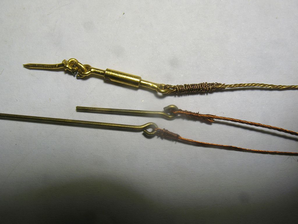
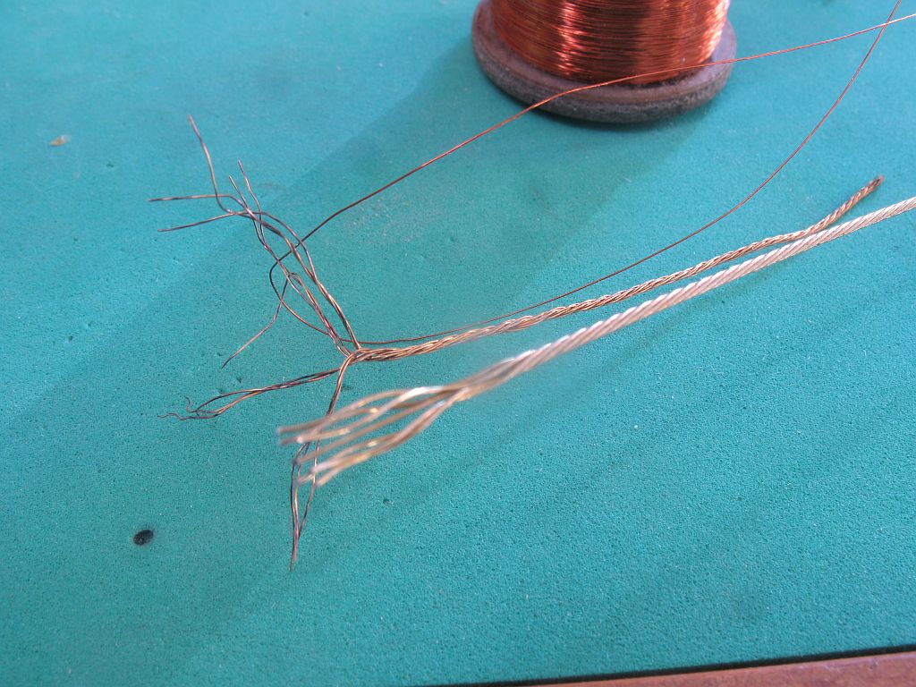
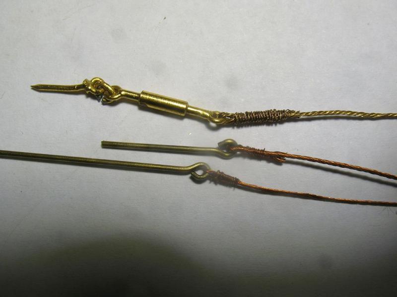
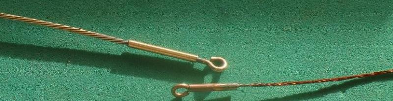
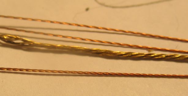
Bob Thanks for the information. I have a spool of .006" copper wire and I have been twisting up a few different combinations to see what happens, definitely a different process than the rope. This pic shows the large broken stay off the model and the 2 in the back are 3 strands, the one in the front is 4 strands. I did another experiment with some bright 49 strand Beadalon bead stringing wire that I happened to have in stock it is .024" some of the pictures on the web of older ships and the stays looked like they were folded through the thimble and whipped the copper wire in this picture is too heavy .006" but this might be a path with the right diameters of Beadalon and fine whipping wire. Michael
- 749 replies
-
- 13
-
-
- albertic
- ocean liner
- (and 2 more)
-
I am still having trouble with the bulk uploading of pictures any ideas as to why the latest version of flash doesn't work for this? I have looked at quite a few pictures now of funnels and their attendant staying, there seem to be quite a variation in methods. I think that proper looking cables and endings will improve the appearance of the stays. Roger thanks for the comment about Lloyd McCaffery, do you have a link or reference? Jbshan, yes I will certainly do a better job of the ends of the cables. This of course is an area that will no doubt cause some to be concerned regarding making this model look "original" It is not in my genetic make up to make something look wrong on purpose though. Jud thanks for stopping by. Michael
- 749 replies
-
- 6
-
-
- albertic
- ocean liner
- (and 2 more)
-
Very nice work on the boom buffer. the tree-nailing looks pretty nice too. Michael
-
The diameter of the steel cables holding up the stacks on the Titanic are noted in one source as 1 1/4 inch in diameter. I would think that the cable stays for the Albertic would not be any larger than that. At 1:100 the stay diameter would be .0125" which is close to 30 gauge in this chart of sizes. This would be smaller than the .028 measure on the model. Michael
- 749 replies
-
- 4
-
-
- albertic
- ocean liner
- (and 2 more)
-
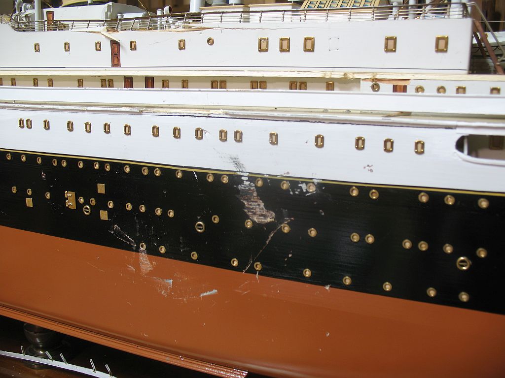
Hi John I am thinking something like this as subtle as possible the light colour is just to show the concept. the area would cover all the damage with the edges repainted along the imaginary plating of the ship around the damaged area It would need the brass ports to be removed the replaced after the painting. Michael
- 749 replies
-
- 7
-
-
- albertic
- ocean liner
- (and 2 more)
-
John regarding the photographs especially the Vallejo Gallery ones, I am glad that I saved the link because it is no longer visible when one goes to the website currently. I agree with you regarding the "Builders Model" designation I am going to see if I can find some good reference photographs of the funnel stays. Something else I have been thinking about as I had to go get water today, musing as I was driving. Regarding the damage on the side of the hull if I were to shape an area to represent the area of replacing the steel plating on a real ship by demarcating the area in a linear way with the paint matches it would allow me to pretty much hide the repair, what do you think? Michael ps I am having trouble uploading using the advanced upload, I have the latest version of flash and am using the latest version of Firefox The basic works but is a pain to have to go through so many steps Help Please
- 749 replies
-
- 4
-
-
- albertic
- ocean liner
- (and 2 more)
-
Denis I am thinking that I might replace all the funnel stays. Joe , yes is was kind of Brian to make the recommendation. Jack, that has occurred to me but I think making new cables might be easier. John, if you look at this model it appears to have all the hallmarks of being made by the same model builders but an upscale version, I am not sure that they are correct either although they look much tidier. I am wondering about replacing all the funnel cable stays This model appears to be the same level as the one I am restoring. Given the number of guy cables that have been damaged My preference would be to replace them with new properly laid up cables. What is the opinion of the experts? The model will go back on public display at a future date in a contemporary enclosure appropriate to the vocabulary of the architecture of its surroundings. Thanks Ed for your encouragement. Michael
- 749 replies
-
- 7
-
-
- albertic
- ocean liner
- (and 2 more)
-
I am having trouble uploading using the advanced upload, I have the latest version of flash and am using the latest version of Firefox The basic works but is a pain to have to go through so many steps Help Please Michael
-
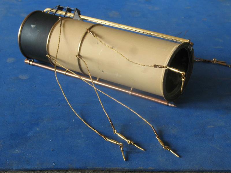
Thanks bob, I am looking at the cable damage and have some thoughts that I will have to make my own to make it match the last picture shows some 34 gauge copper wire and some control line stranded it is a little heavier but the difference in the look of both types leads me to think I will need to make up some strands of cable using my rope making skills Michael


- 749 replies
-
- 10
-
-
- albertic
- ocean liner
- (and 2 more)
-
I was just looking at the "cables that are used for the funnel guy cables. they are made from 4 groups of 3 wires cable laid the individual wires are brassand are .007" which is 34 gauge on the Stubs Wire or Birmingham gauge which was likely the standard used by Bassett Lowke. Anyone know where I can get some rather than making my own, I do not want the aluminum 34gauge that is brass coloured sold by the craft folk. I have had a cursory look on the web but really do not need a Ton of the stuff from Alibaba. Michael
- 749 replies
-
- 4
-
-
- albertic
- ocean liner
- (and 2 more)
-
Druxey, we must have been typing at the same time, the comment about repaired damage by previous folk made me smile, because there are a couple of the small cage fans pinned to the top of one of the skylights at a 45 degree to each other and obviously in the wrong location. Jack, I can assure you I will not be using any foam, I might end up foaming at the mouth dealing with the hull side though. Michael
- 749 replies
-
- 10
-
-
- albertic
- ocean liner
- (and 2 more)
-
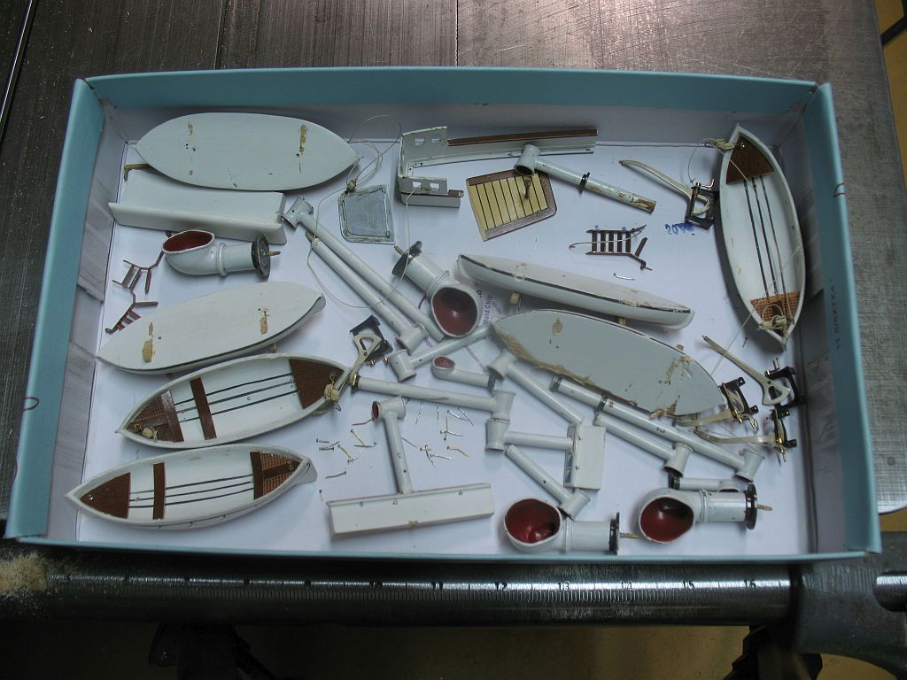
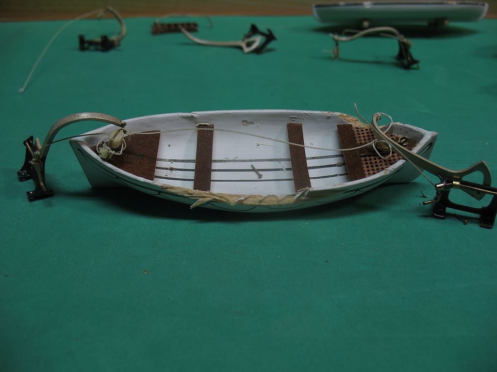
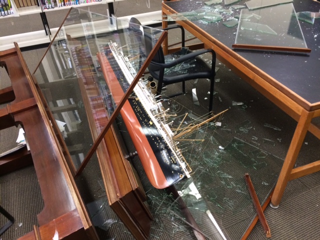
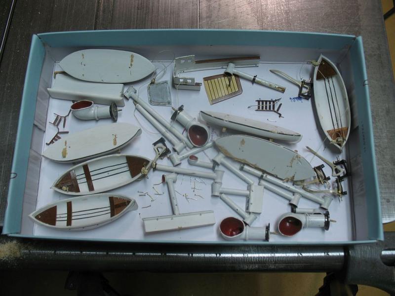
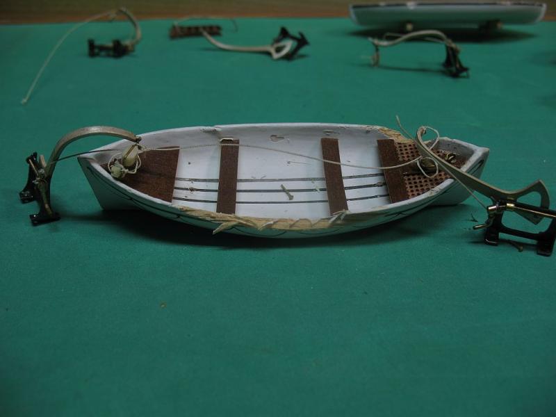
Hi Nils yes the original base had a narrow footprint and the model was knocked over, this was the first image that I saw. It looks like a few of the rectangular port holes got swept up with all the broken glass,when they cleaned up the area. Druxey, I fear you are correct on this score, I also notice that the hull was brush painted (very well I might add) Denis The credit goes to Brian Small, we have crossed paths on a number of occasions related to models, on this site as well as some others, the client contacted Brian and Brian contacted me. Scott I would think that they had a very sinking feeling. Denis funny you should mention the lifeboats, I woke up in the middle of the night and I started to think about what I had let myself in for and specifically thought about the lifeboats, it was a standard practice in England to use Jellutong for a lot of small parts like these, and I just happen to have lots of scrap bits of Jellutong. I plan to scarph in small bits and re-carve those areas. Michael
- 749 replies
-
- 15
-
-
- albertic
- ocean liner
- (and 2 more)
-
Thanks for the interest and positive comments I have started to do some background research and came across this wonderful image it would make a great painting. Michael
- 749 replies
-
- 12
-
-
- albertic
- ocean liner
- (and 2 more)
-
Hi Denis it is so interesting following your thinking and how you are able to cobble the disparate parts into a convincing winch unit that is believable. Michael
-
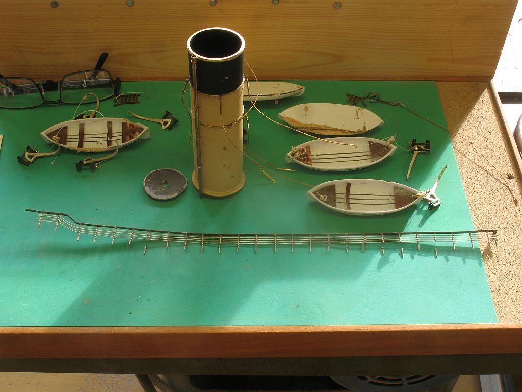
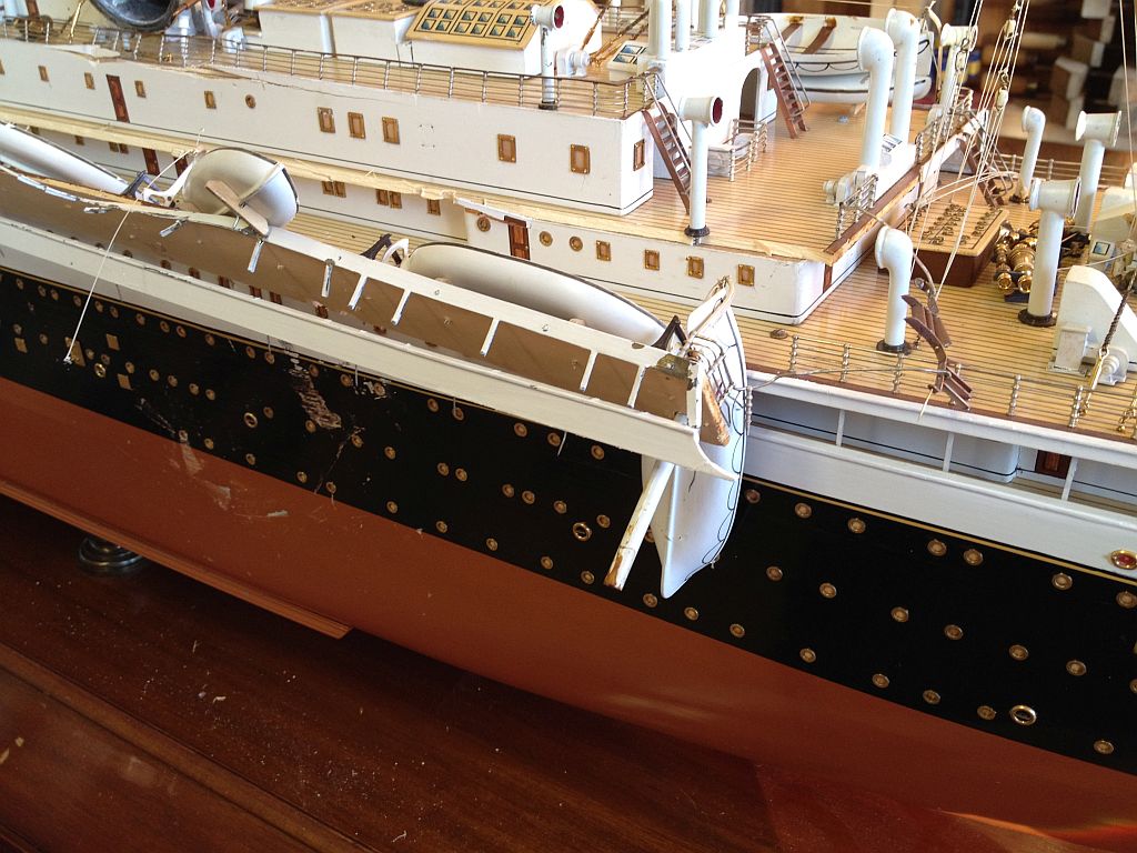
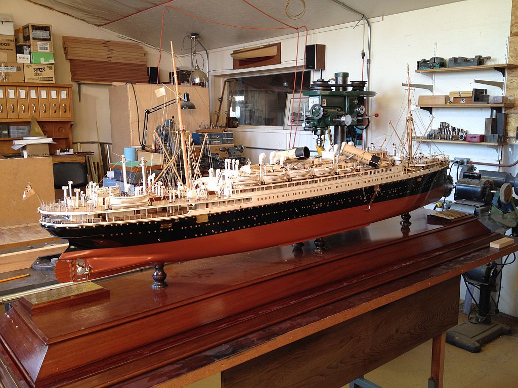
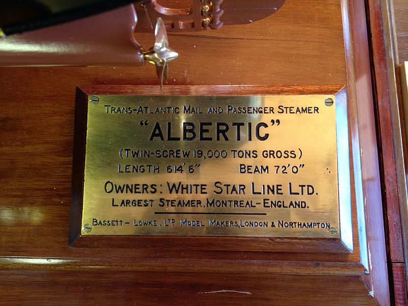
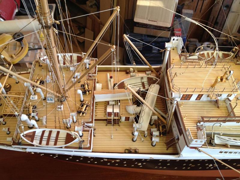
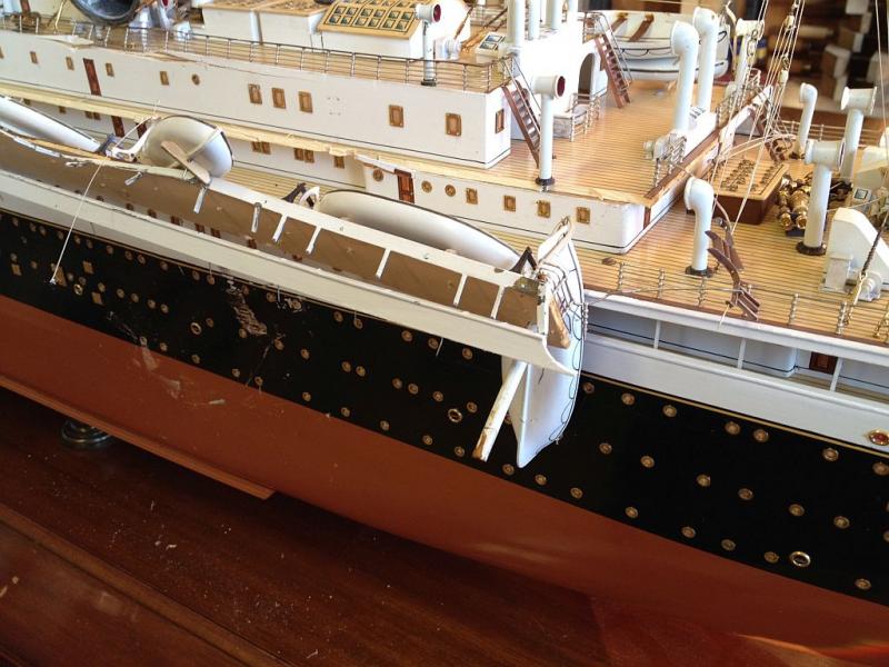
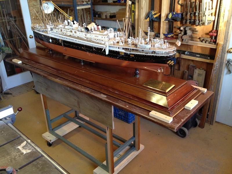
I was recently commissioned to restore to "Original Condition" A 1:100 model of the steamship Albertic. The model was knocked over and sustained considerable damage to the port side lifeboat deck Funnels and railings along with vents and all sorts of lines and wire stays. I have made extensive photographs of the condition as I received it, and have begun recording the removal of the damaged parts that were still attached, A few surprises that were not evident when I viewed it at the clients premises have come to light. I cobbled together a quick trolley so that I can move the model around, I will make a lightweight dust cover to keep the dust off the model. I will no doubt be calling on the expertise of the membership for advice as I move forward. As tragic as the damage is I am hoping that this will be a good experience and that I rise to the occasion with a smile as things become repaired. here are a few pictures to show the extent of my task. Builders Name plate Port side sustained the most damage Starboard side suffered mostly inertial damage The funnels took a beating because they are heavy and brass A lot of loose parts were piled on the deck in front of the bridge The stern end of the port lifeboat deck is badly bent and twisted The stairs didn't fair too well either Below the port lifeboat deck is the most damage on the hull I am really hoping that this area can be reworked without having to repaint the entire side, we will see? A box of the loose pieces now lifted off the ship Ouch This will keep me busy over the next couple of three months. As I was removing all the big loose parts I was noticing how much of the fine lines and wire cables have also been damaged. many of the parts were attached with micro brass pins, all the lifeboat davits for instance. Michael


- 749 replies
-
- 32
-
-
- albertic
- ocean liner
- (and 2 more)
-
Very nice work Aviaamator, the precision of your treenails is admirable. Nice also to see your son helping, such a great experience for him. I hope your health is improving well. Michael
-
Thanks for you quick answer Chuck. OK I looked up Albion tubes Are these the tubes you are referring to? and that of course leads to the next question what type are the ones you have used because your results speak for themselves. Michael
- 1,051 replies
-
- 4
-
-
- cheerful
- Syren Ship Model Company
- (and 1 more)
-
Hi glen that makes sense, It also occurred to me that you can also thin the inside edge before rolling so that the entire length of the seam looks thinner as if you had used a thinner material for the tube, while maintaining the serviceability of the thicker material. Michael