

CDW
-
Posts
7,719 -
Joined
-
Last visited
Content Type
Profiles
Forums
Gallery
Events
Posts posted by CDW
-
-
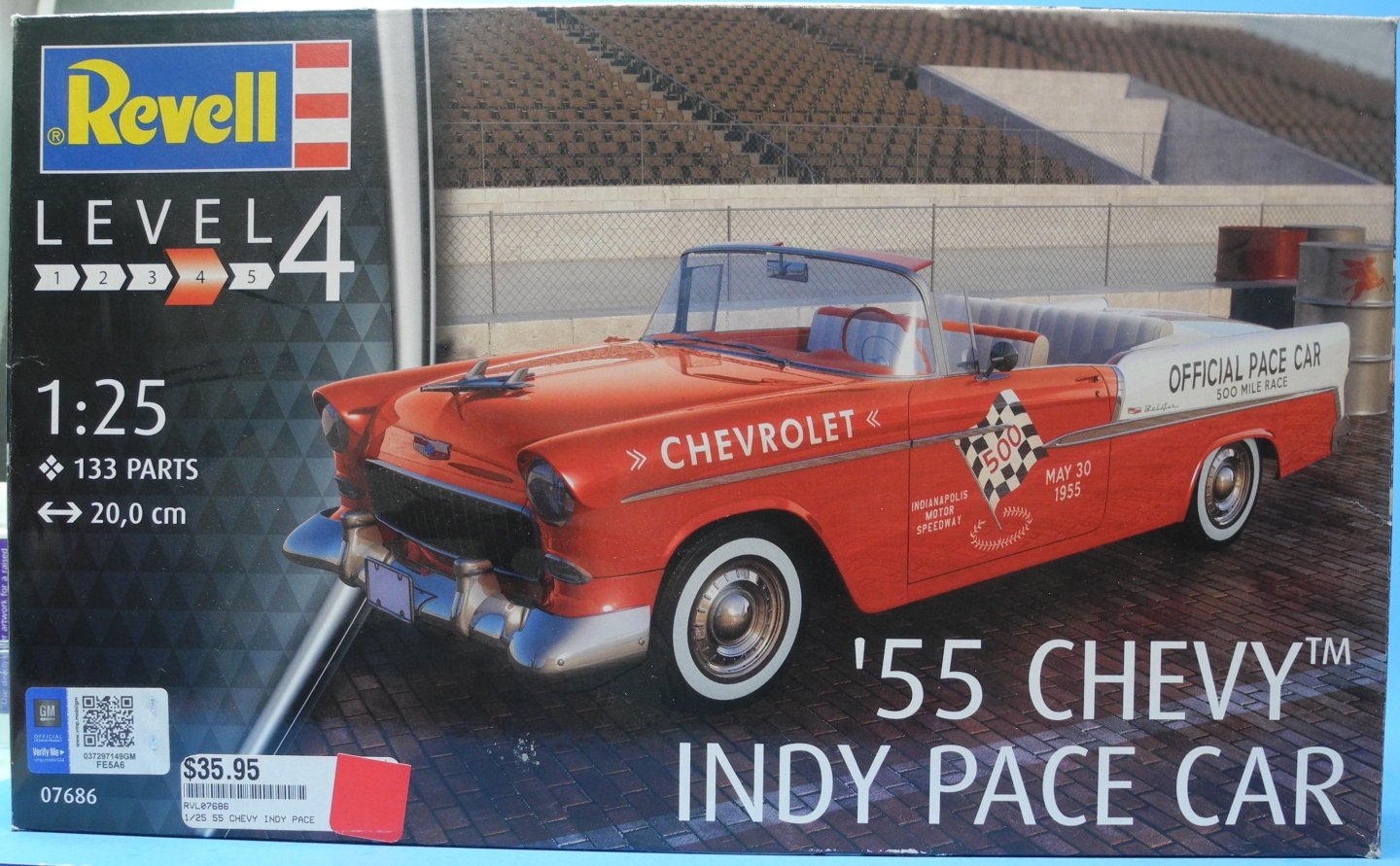
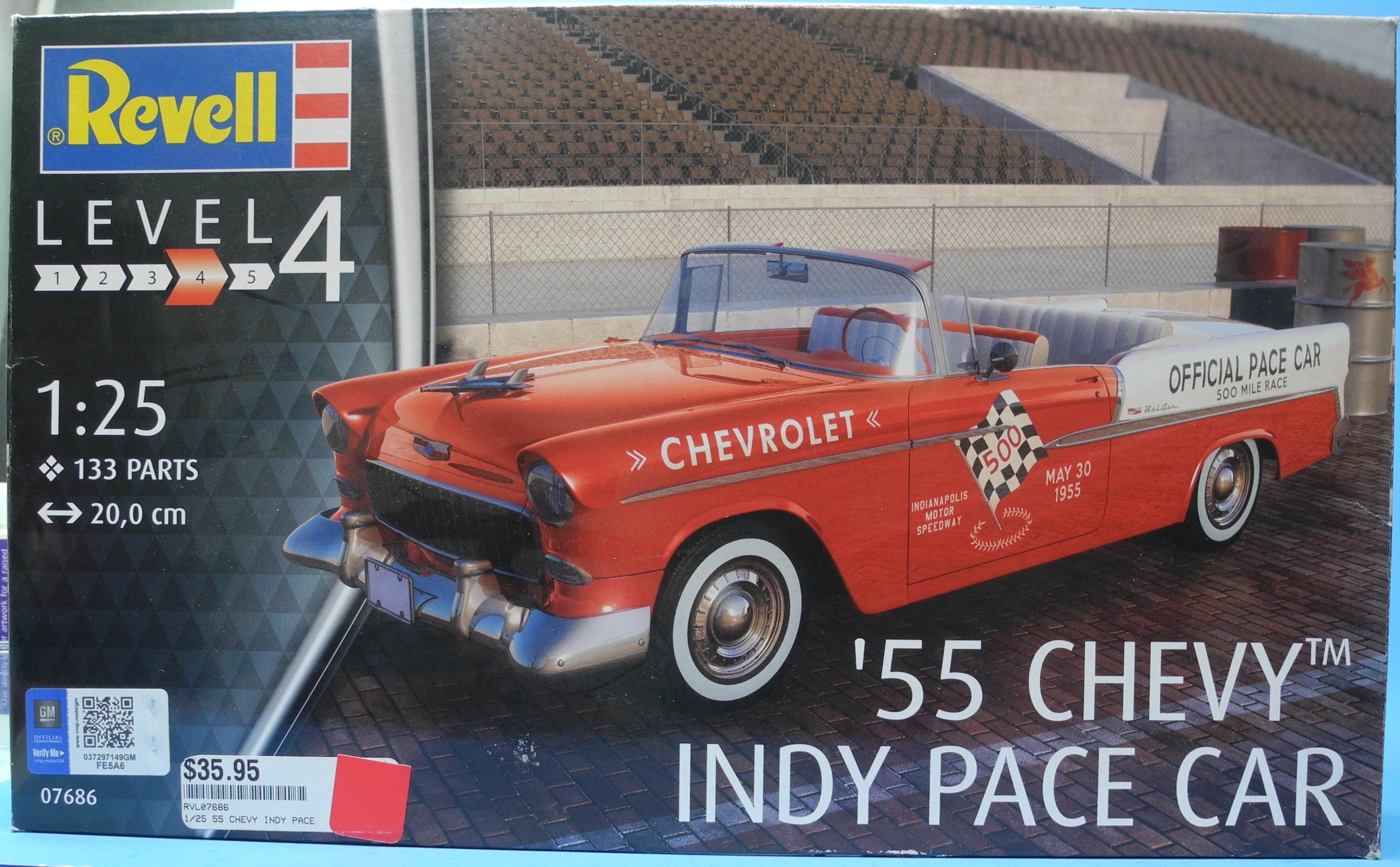
The Revell 55 Chevy Convertible Indy 500 Pace Car is one of three model cars I plan to complete in time for the upcoming Southlandz 2025 Spring Model Car Show, June 7, 2025.
I may be biting off more than I can chew in this short time span, but we'll see what happens together.
- Jack12477, thibaultron, gsdpic and 9 others
-
 12
12
-
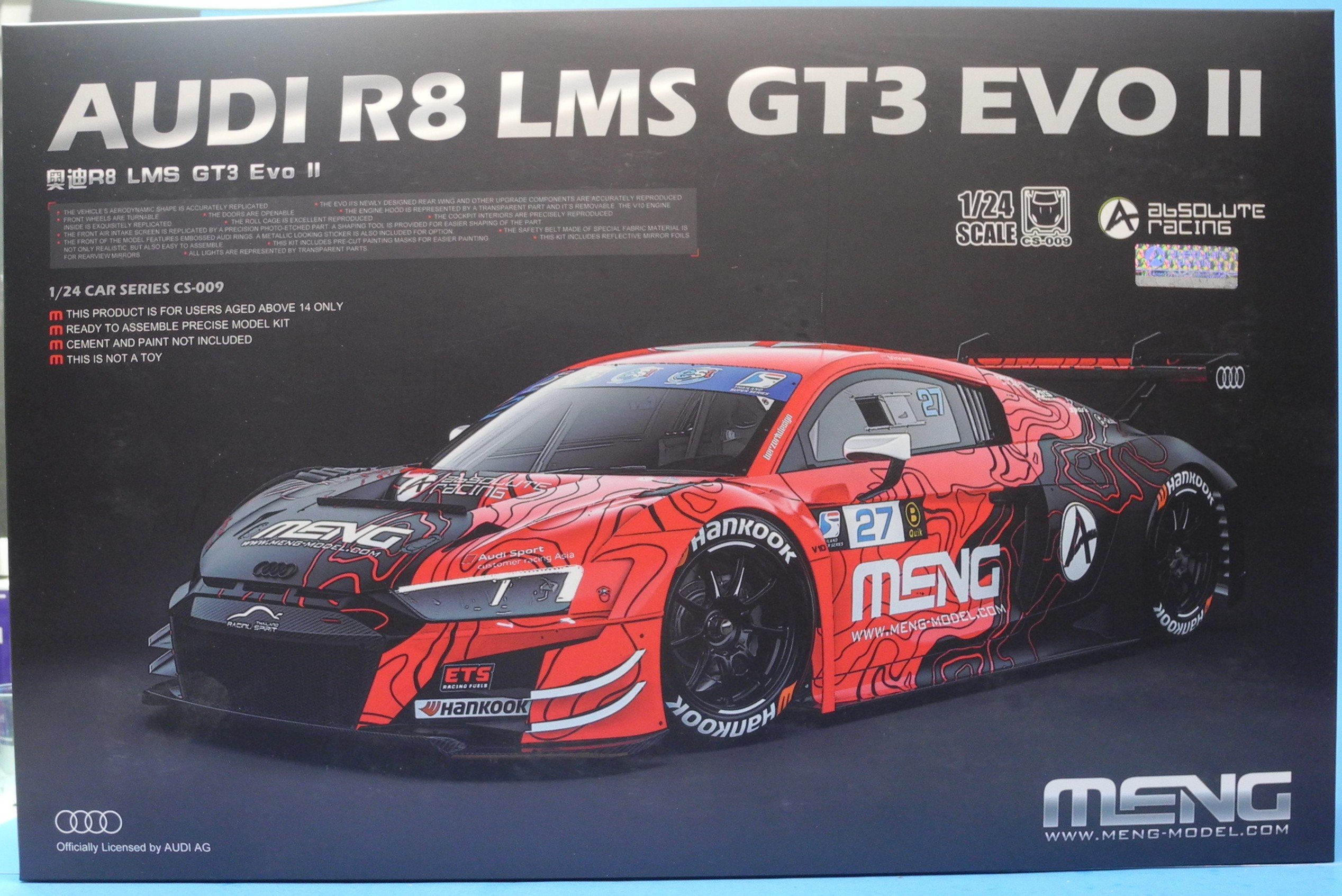
The Meng Models Audi R8 LMS GT3 EVO II is one of three model cars I plan to complete in time for the upcoming Southlandz 2025 Spring Model Car Show, June 7, 2025.
I may be biting off more than I can chew in this short time span, but we'll see what happens together.

- Canute, gsdpic, Old Collingwood and 8 others
-
11
-
40 minutes ago, gsdpic said:
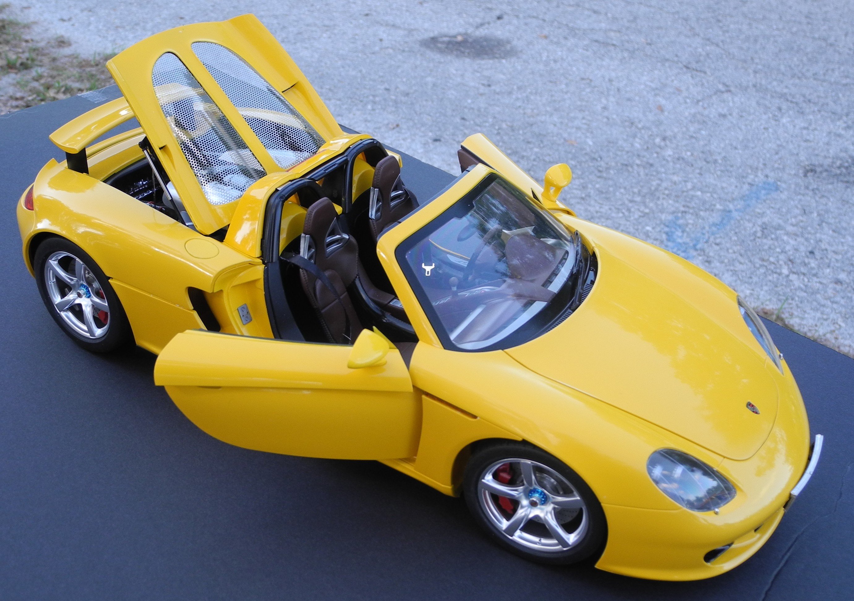
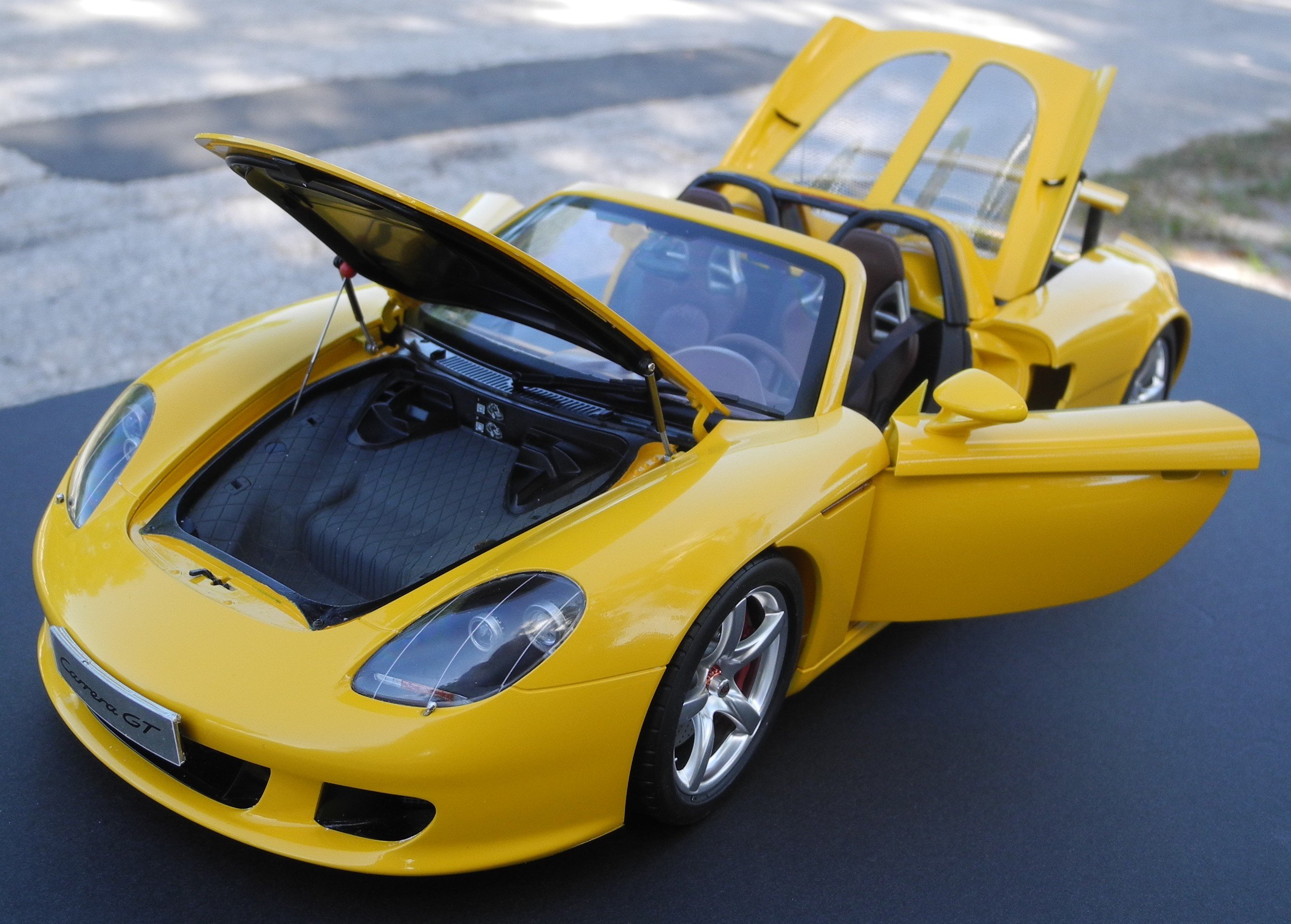
Yes, on the 1:1 car, the t-tops fit into what a Porsche guy would call the "frunk". If you want that extra little bit of detail, you could put a leather strap matching the interior color across the top, holding it down, using the connectors on either side of the inside of the frunk.
That's a great idea. Thanks!
- Canute, Old Collingwood, Jack12477 and 2 others
-
5
-
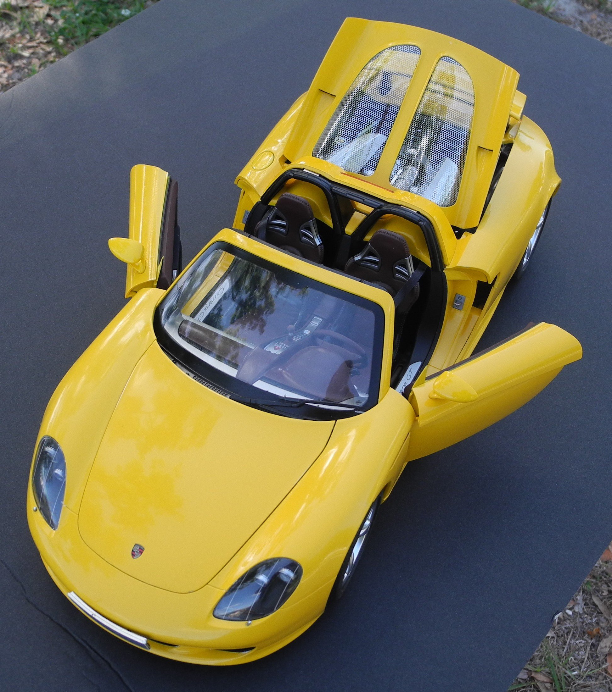
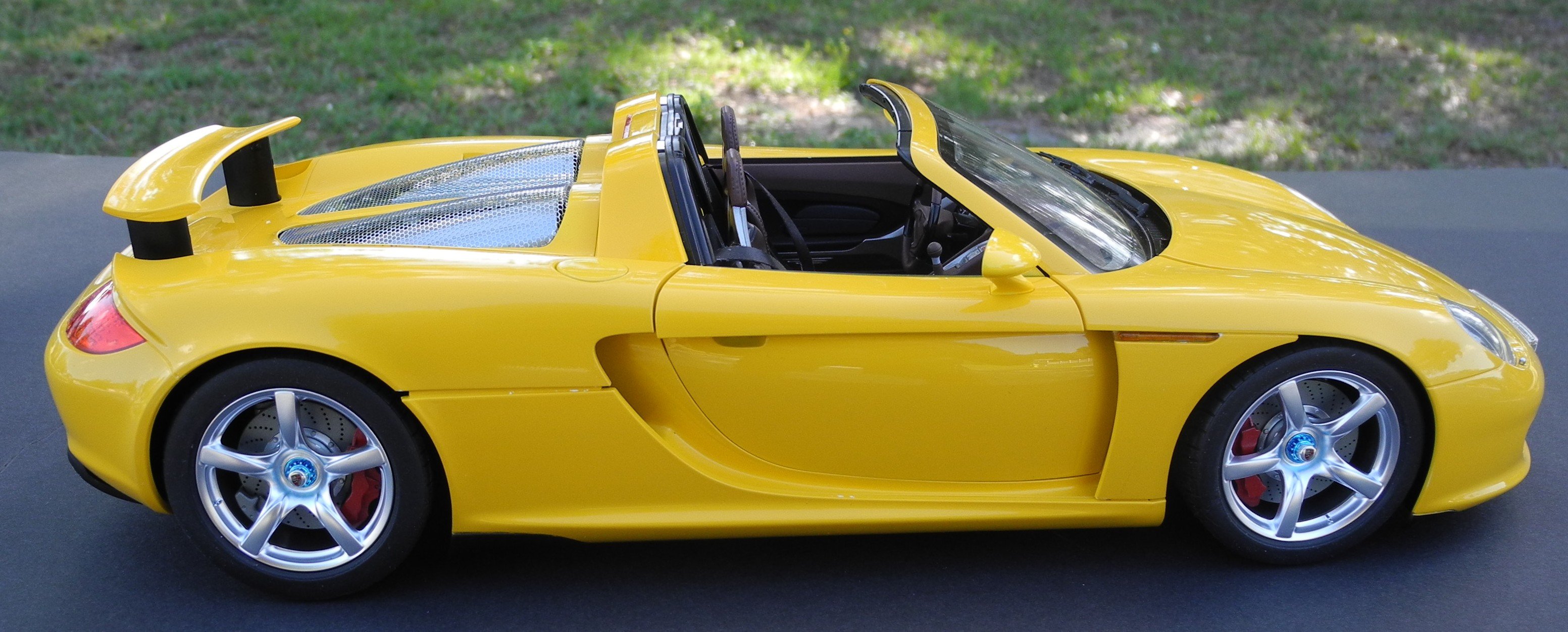
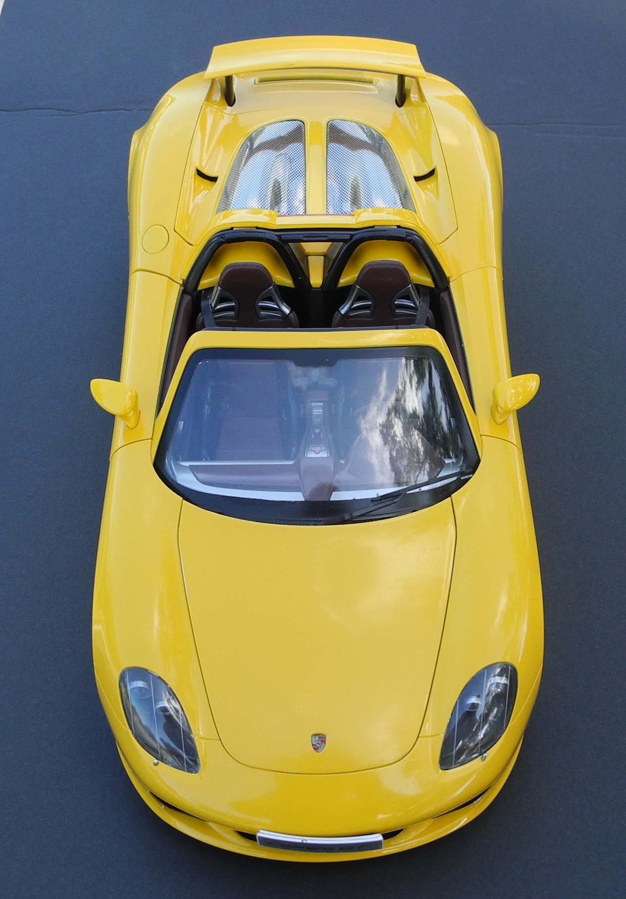
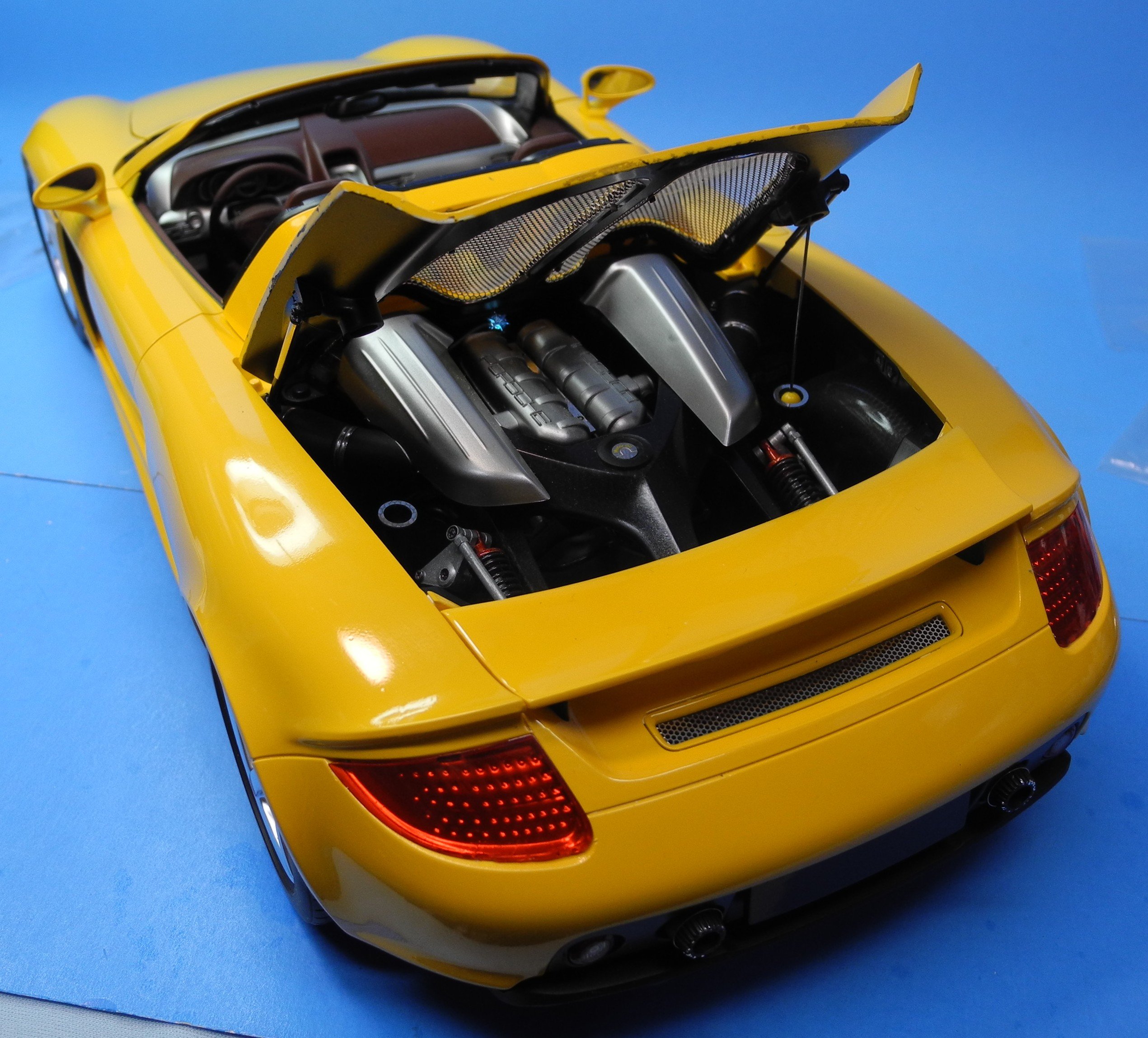
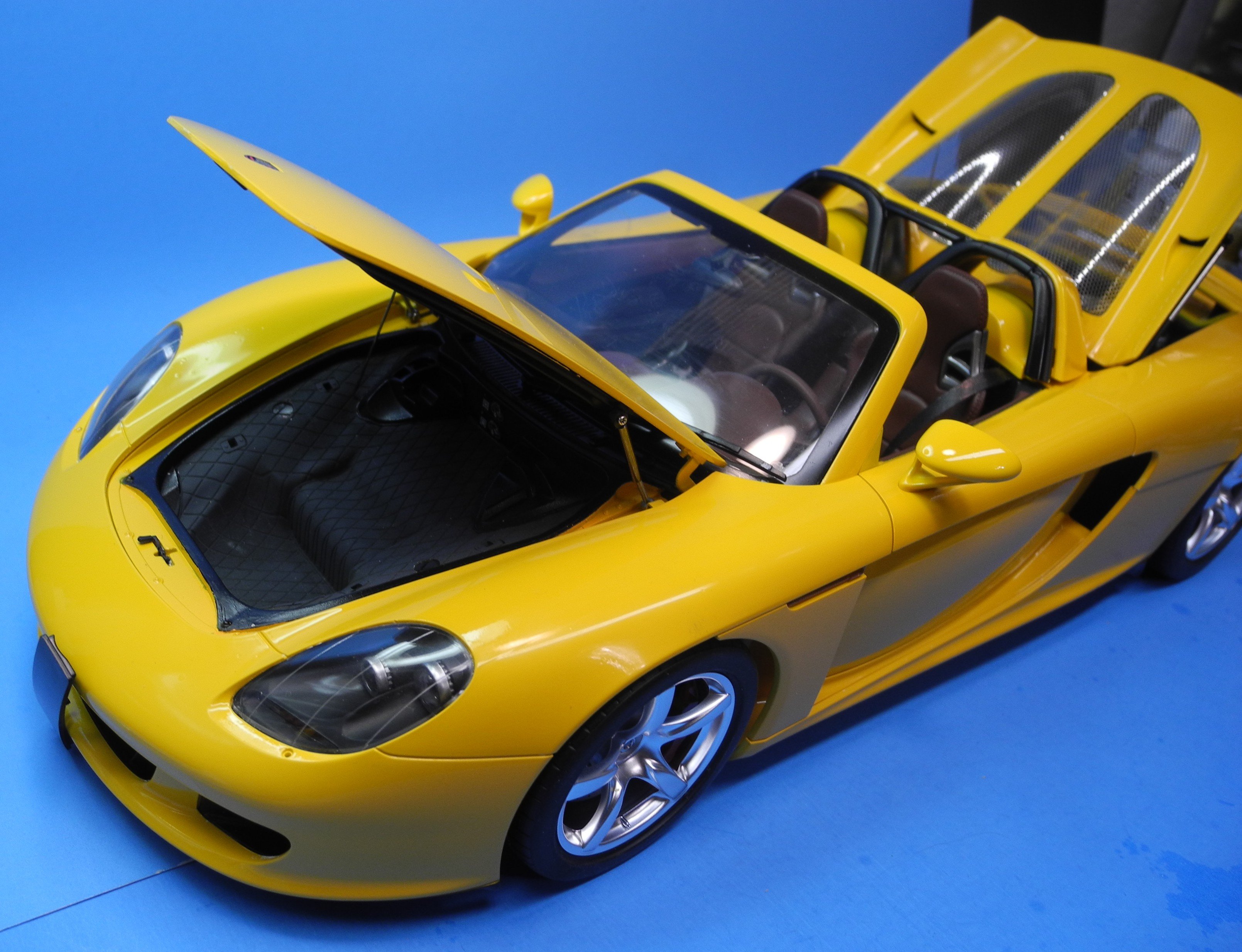
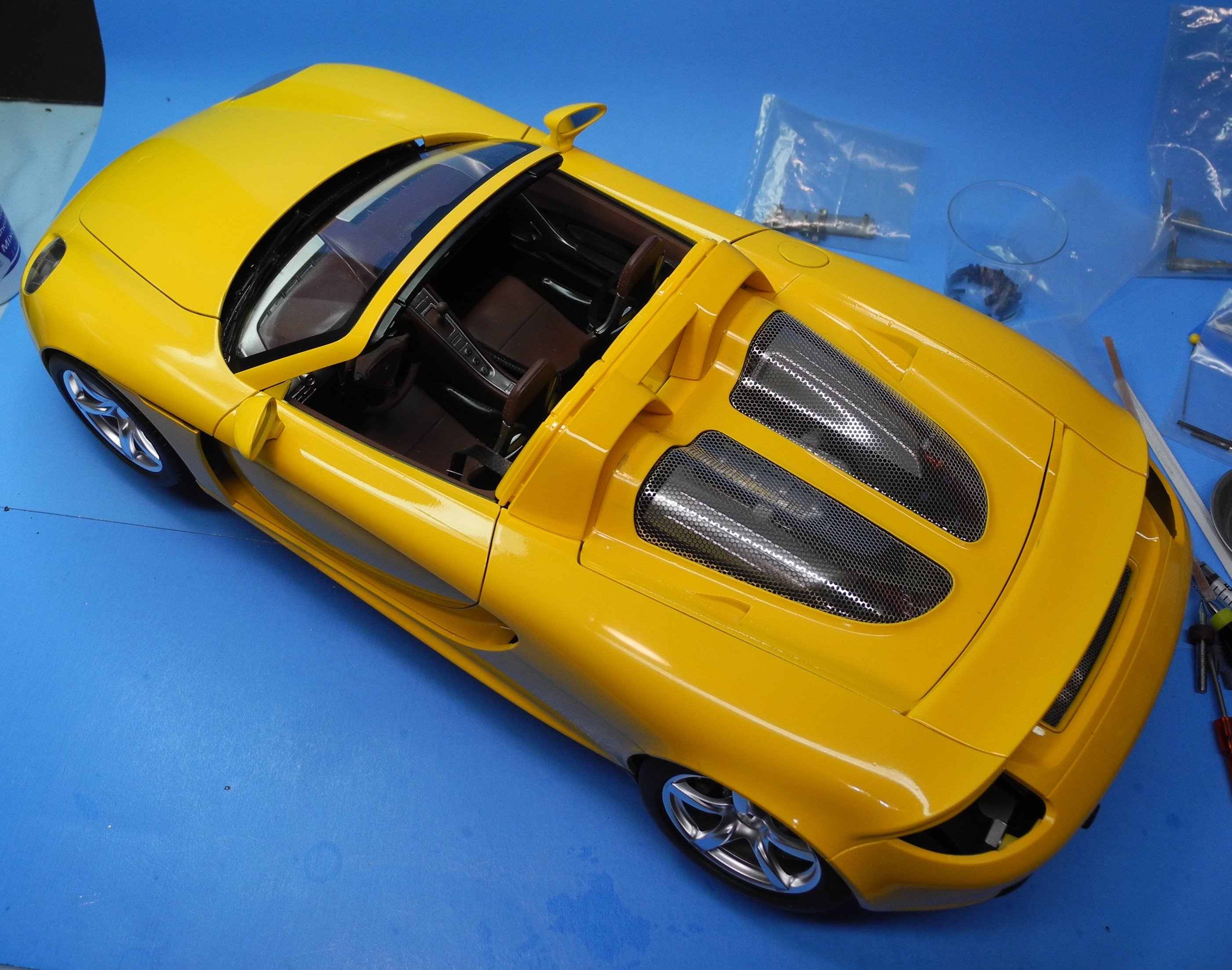
Tamiya cleverly designed the T tops to snugly fit inside the trunk. I guess it mimics the way the tops are stored away on the 1:1 car, but I am not certain.

-
-
That Tamiya aftermarket chain was an e3xercise in frustration for me. I'm hoping you will find the key that unlocks the secret of building it.
I would get mine all built, then when I tried to build and connect the last links, it would begin to fall apart for me, most of the time various places all at once.
I tried over and over again to no avail. In retrospect, I should have bought a Spot models chain set.
-
-
Mail call, got here today.

How should I proceed with my build, separate thread or here?
-
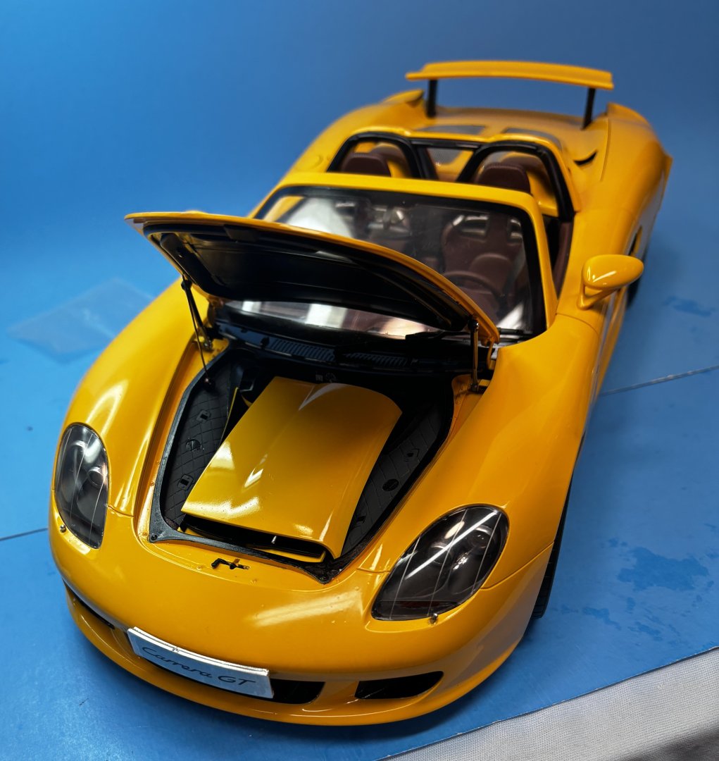
10 minutes ago, yvesvidal said:
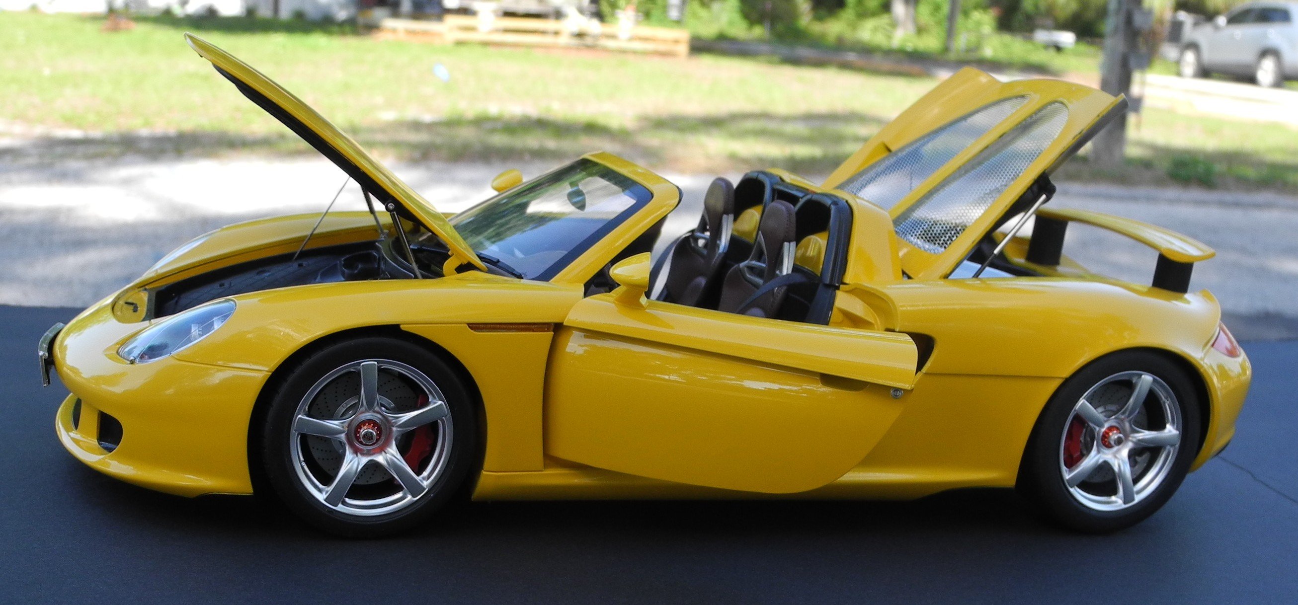
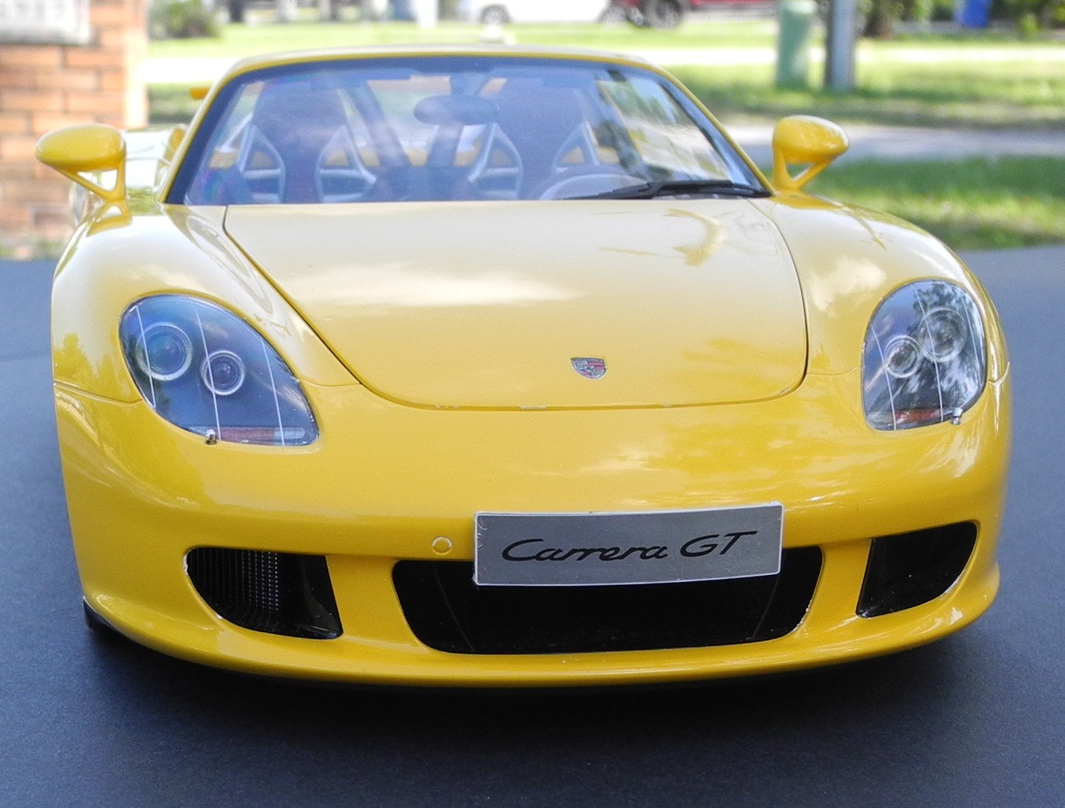
Your neighbors must be envious to see that beautiful Carrera GT in your driveway.
Fantastic model Craig.
Yves
Or steal it for a joyride. 🙂
- Jack12477, Old Collingwood, Canute and 2 others
-
 5
5
-
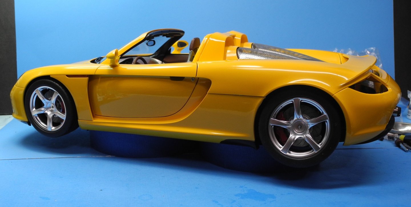
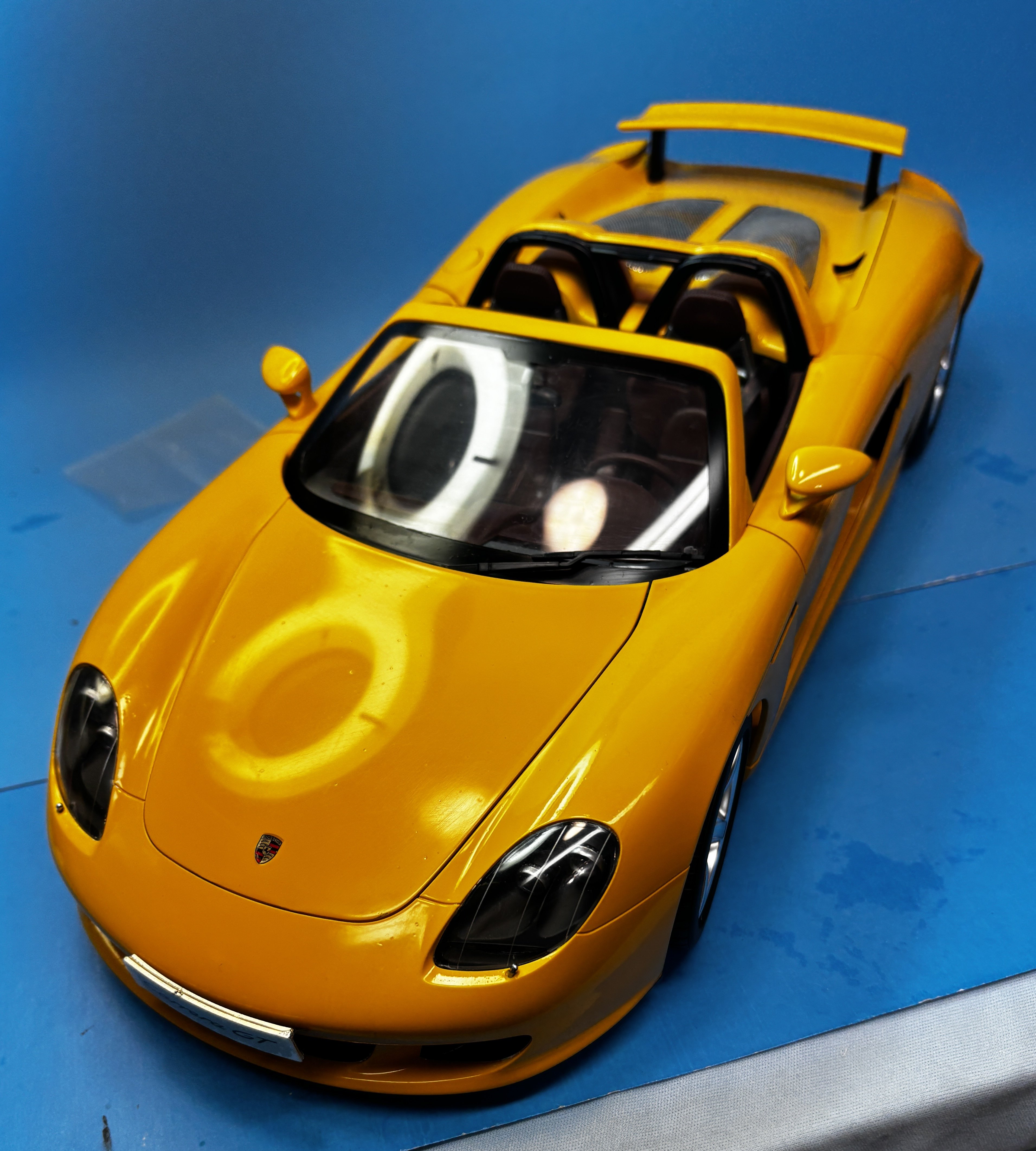
2 minutes ago, Danstream said:
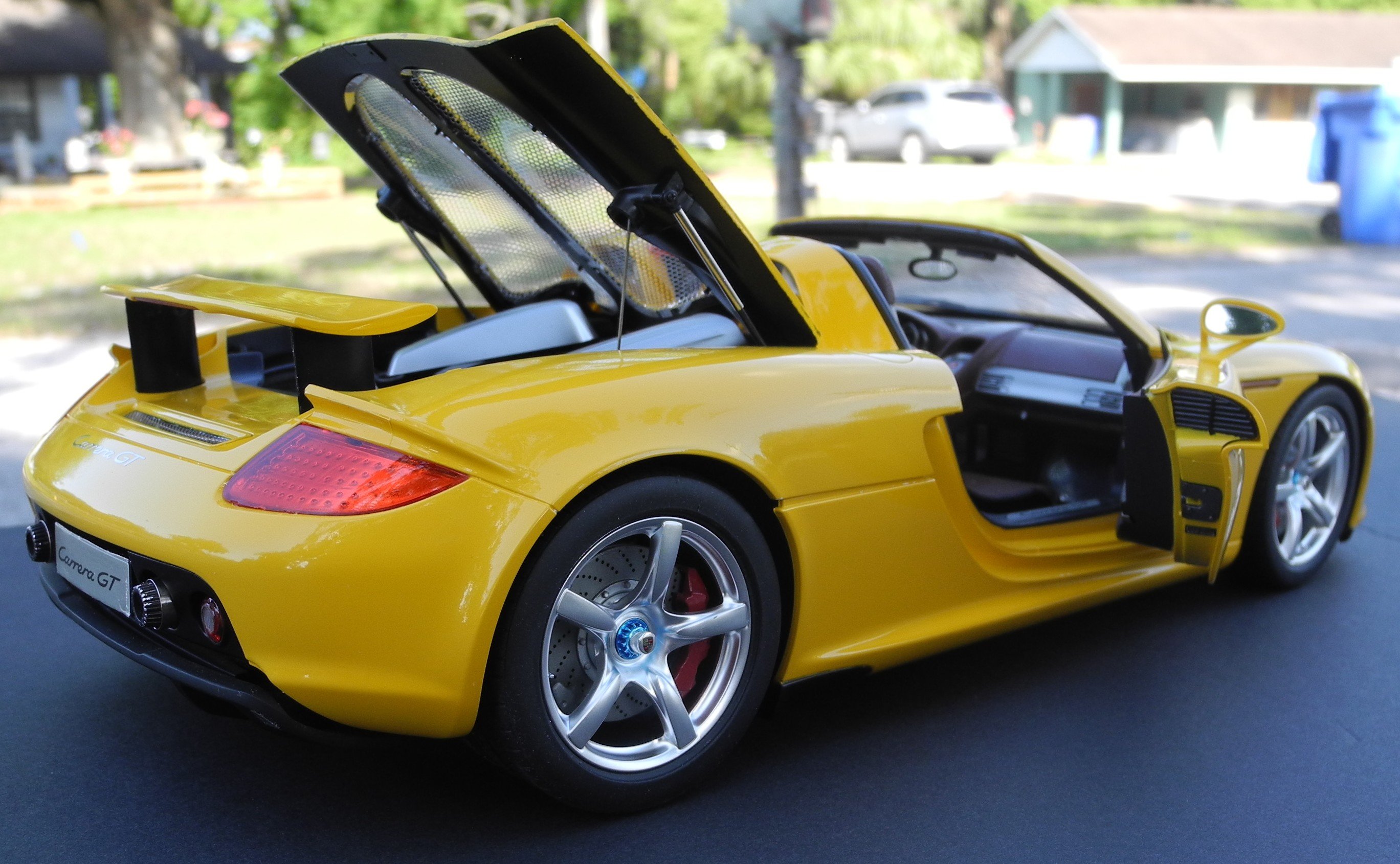
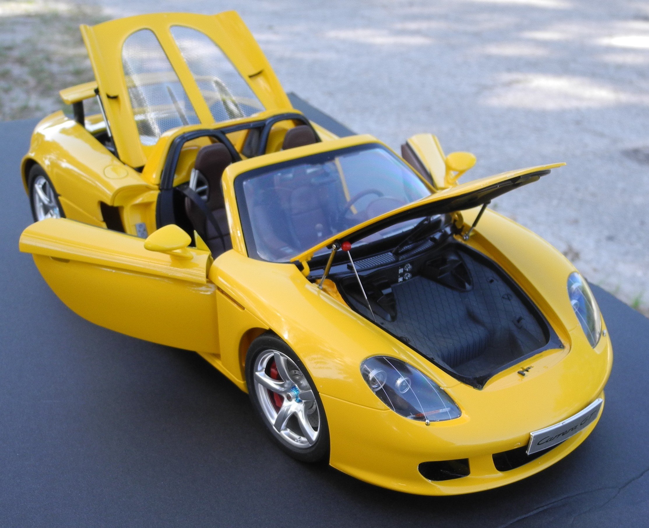
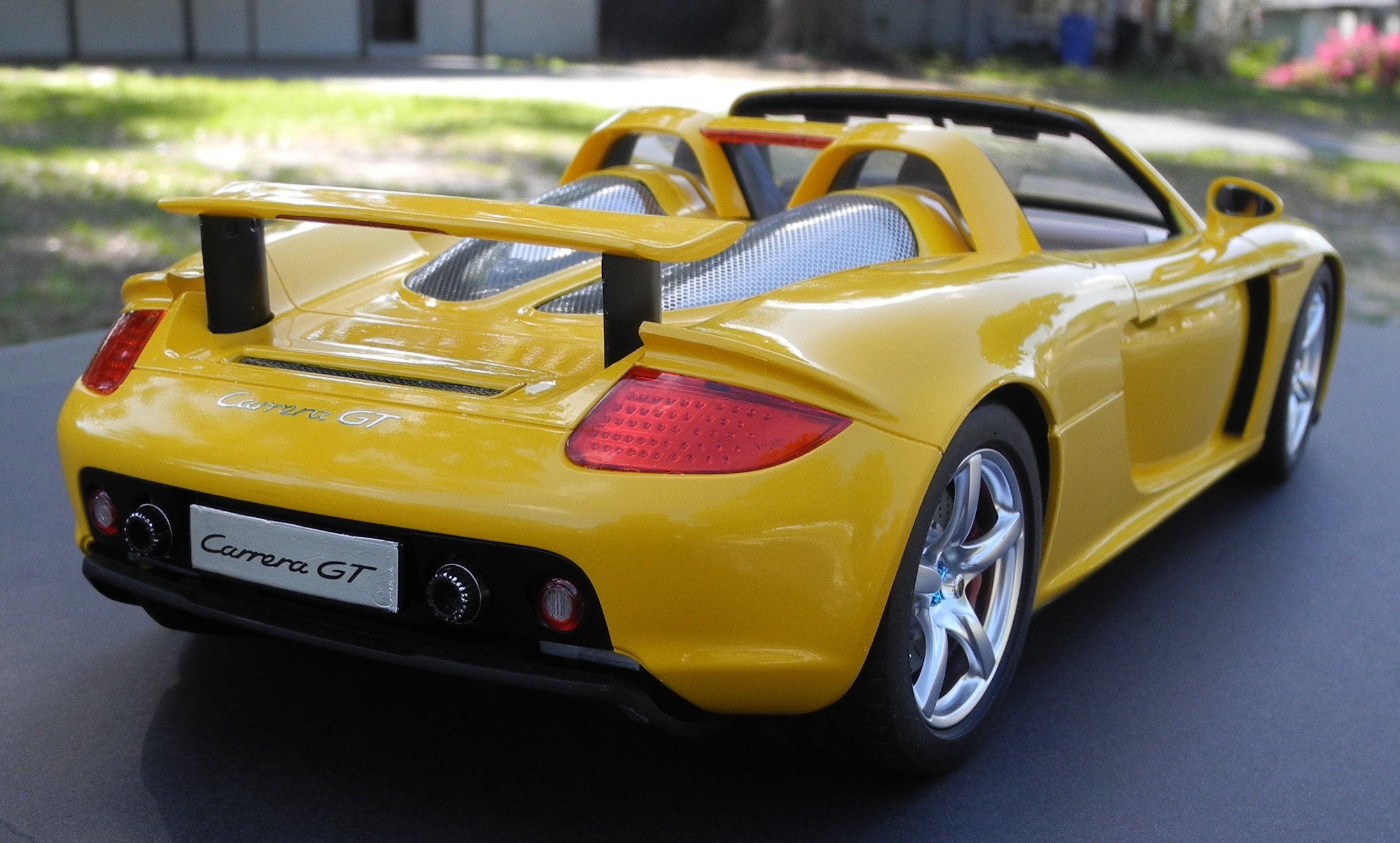
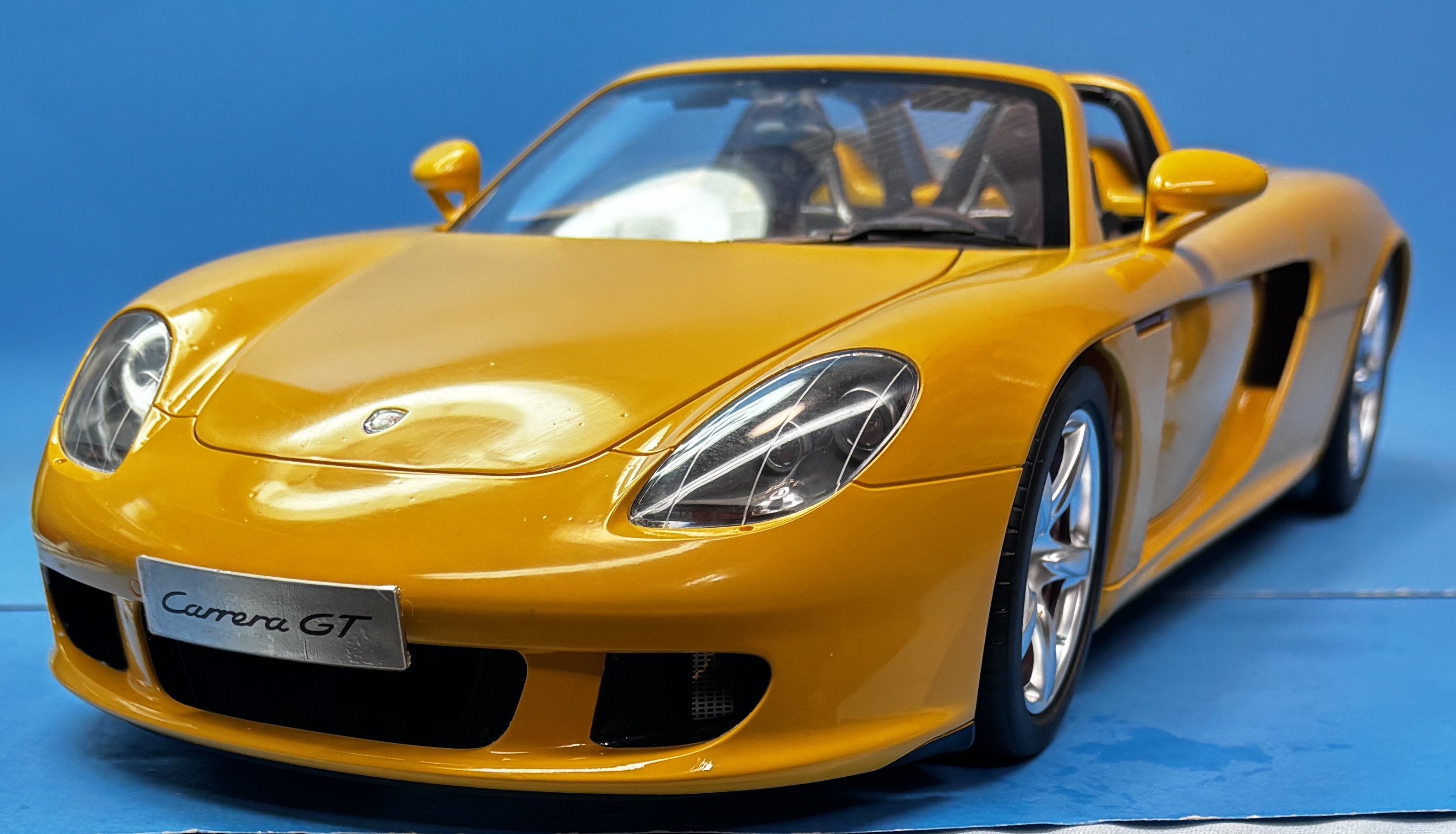
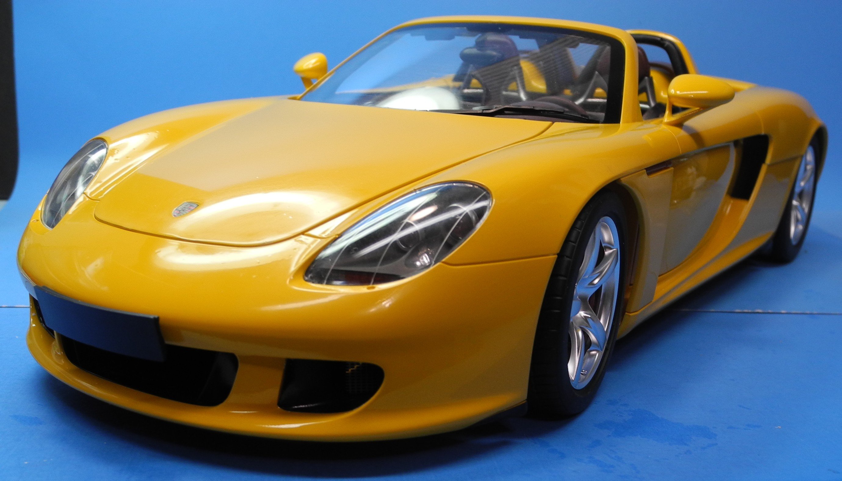
Spectacular! I could hardly tell this is a model. Details and finish are awesome. One thing (among many) that I find incredible is that the paint reflects light like a real car, with smooth and regular reflections. I can well believe that this is the closest thing to owning a real cabrio Porsche Carrera.
Congrats,
Dan
Thanks Dan. It's the closest I will get to owning one.
32 minutes ago, Jack12477 said:Beautiful! Fantastic color / photos
1 hour ago, Tim Moore said:That’s just crazy good. Perfectly finished, well done.
1 hour ago, king derelict said:A beautiful model Craig. The paint finish is spectacular and the details are superb. In several of the photos it looks completely real.
congratulations
alan
Thanks for the kind words gentlemen.
- mtaylor, Old Collingwood and Canute
-
3
-
-
-
-
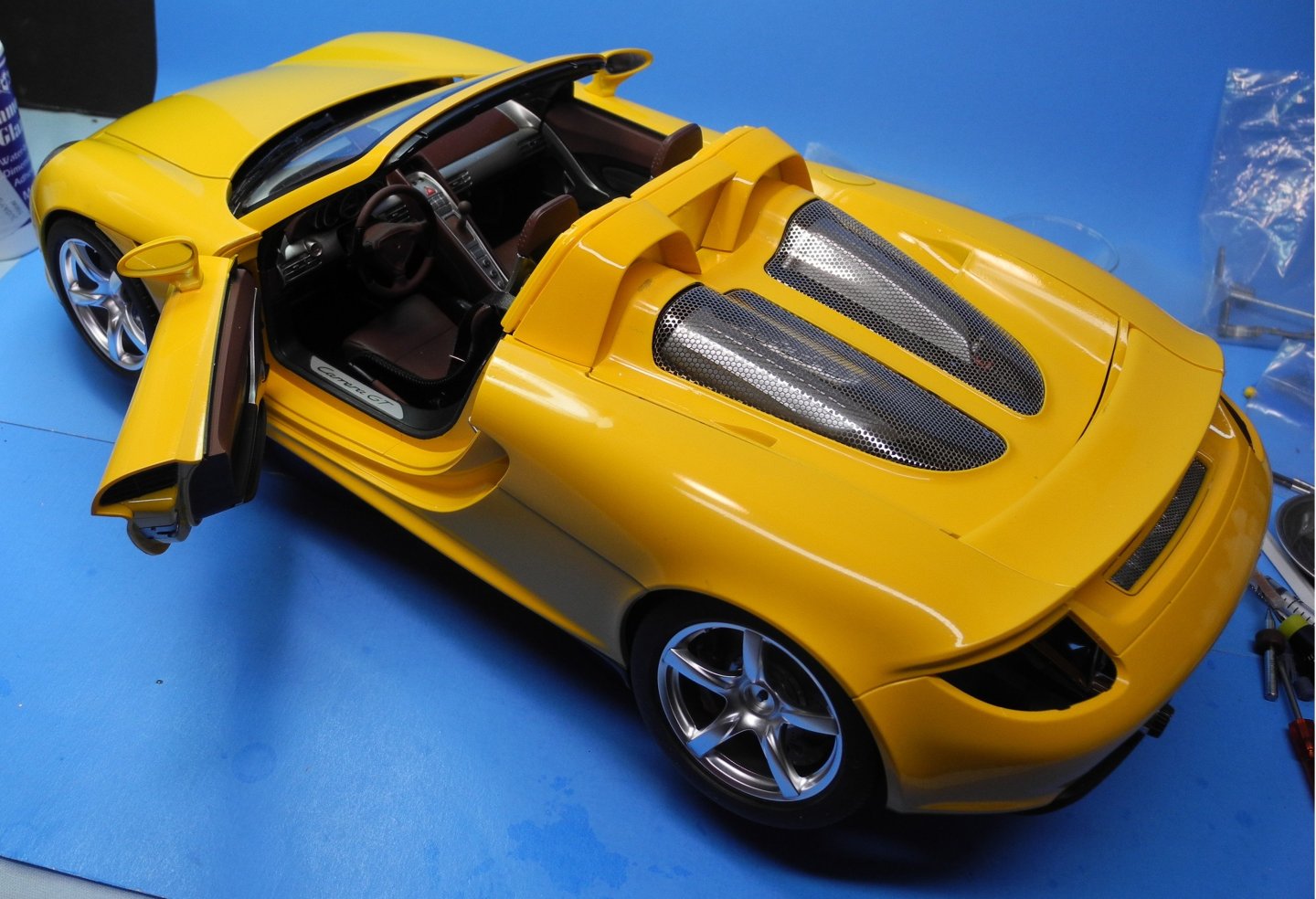
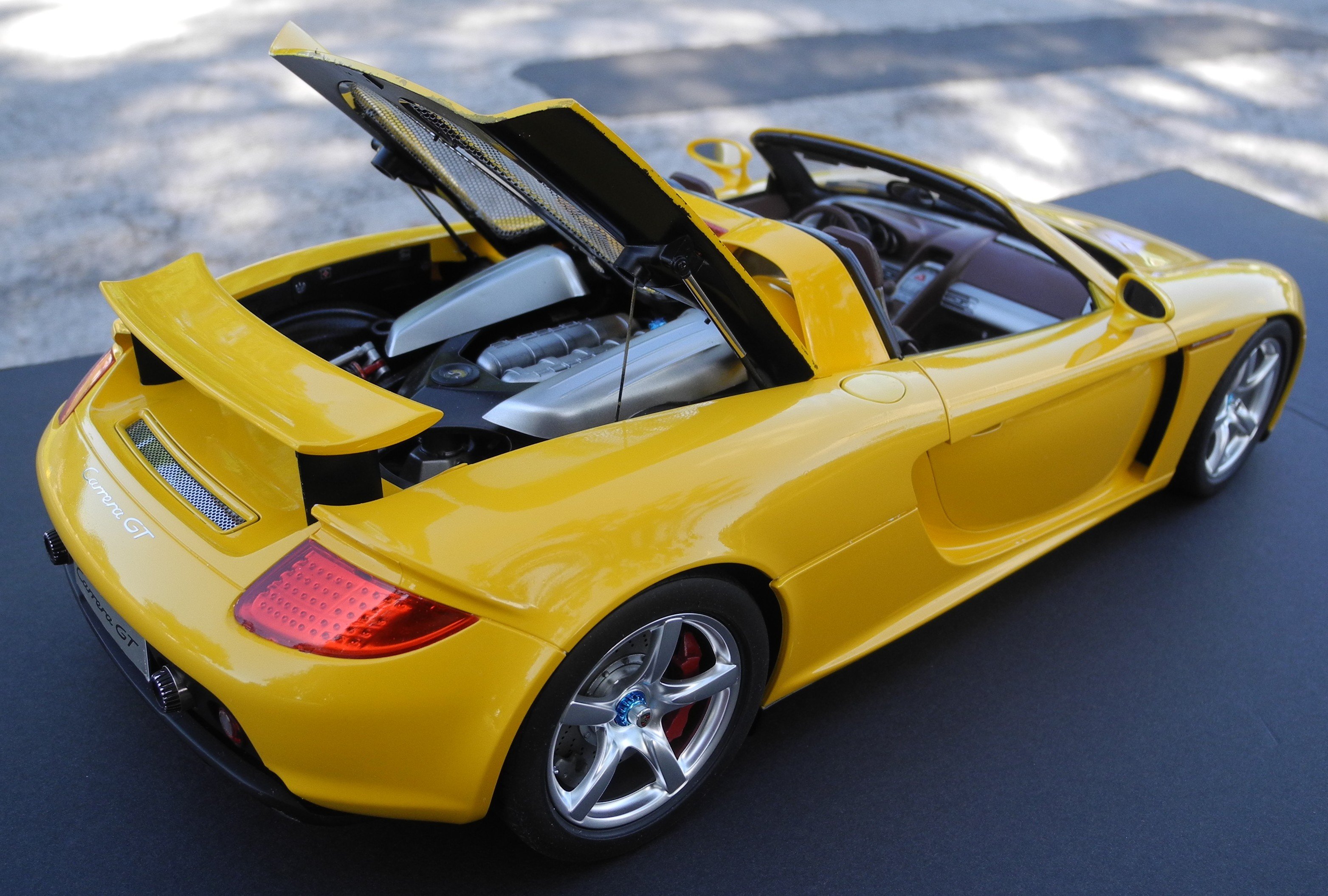
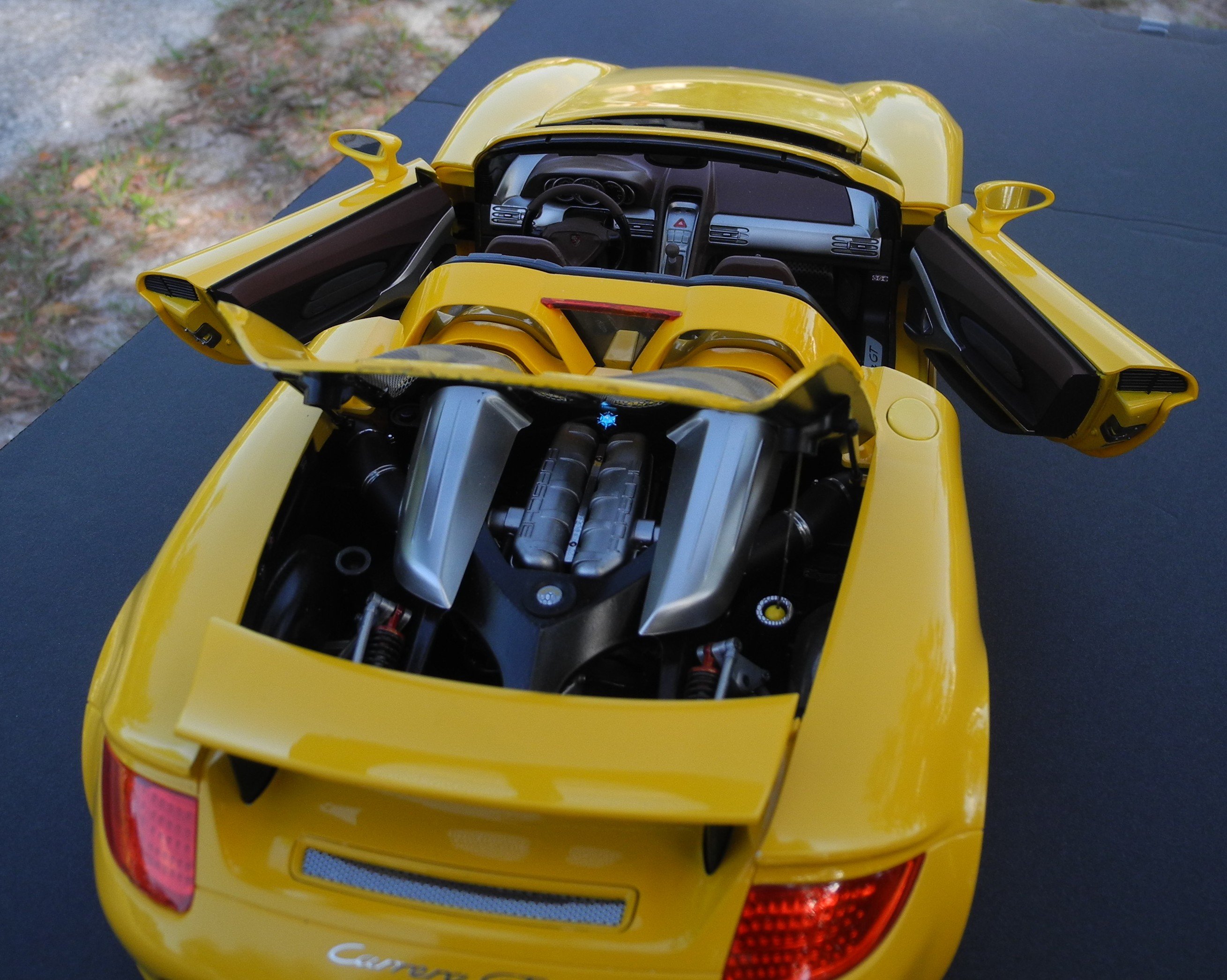
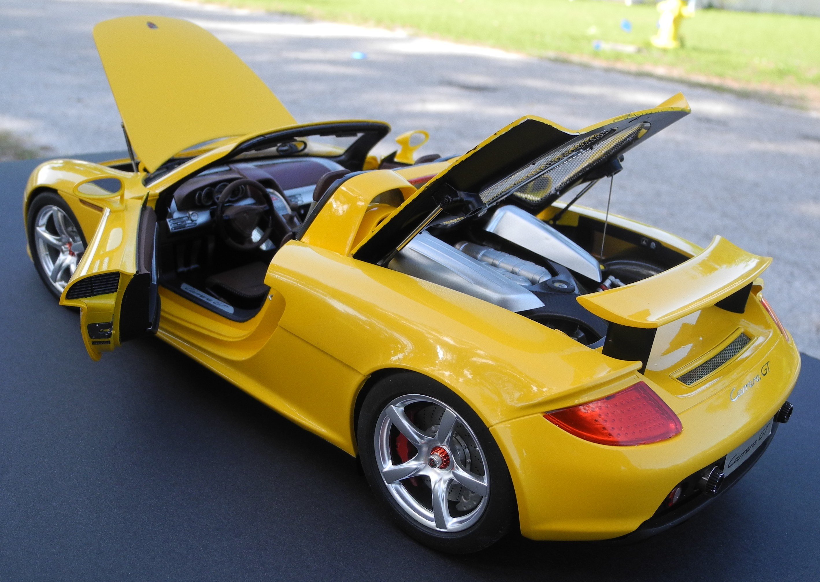
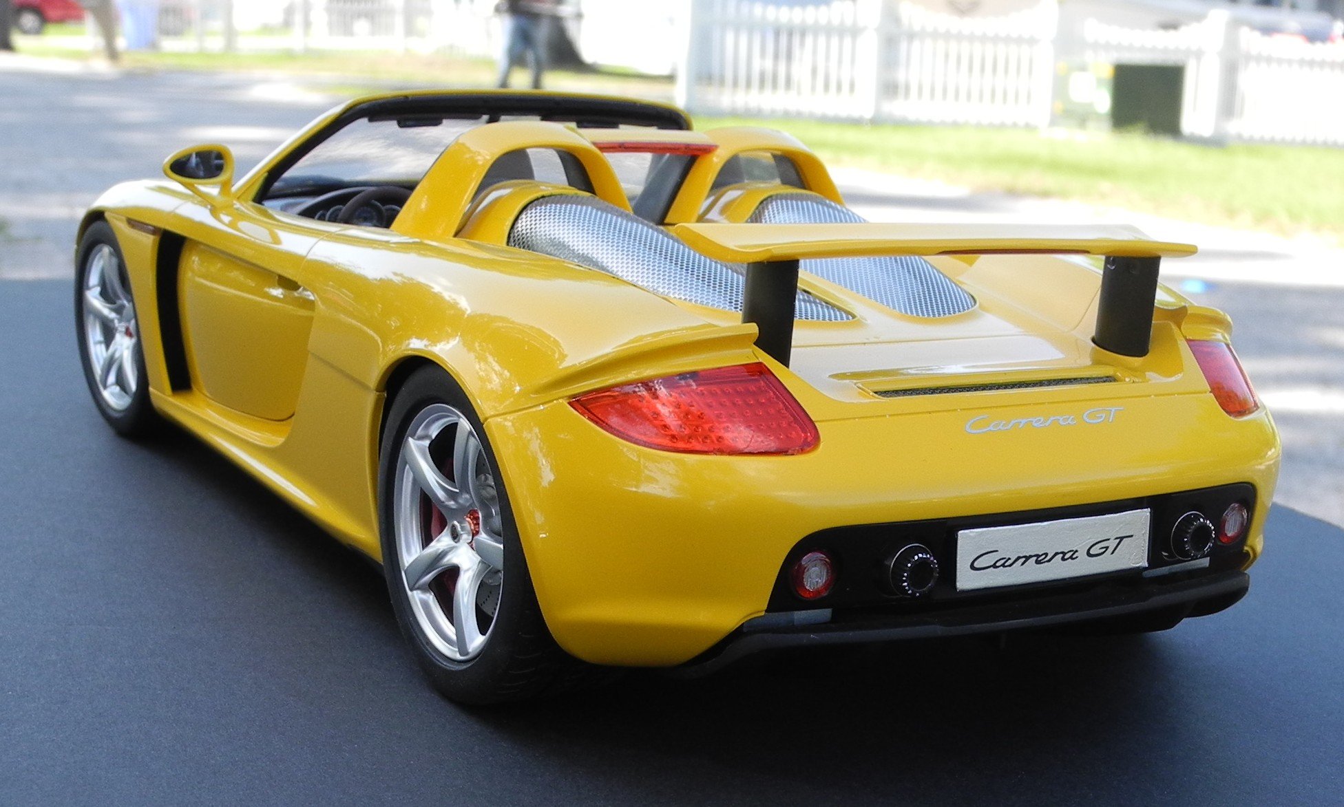
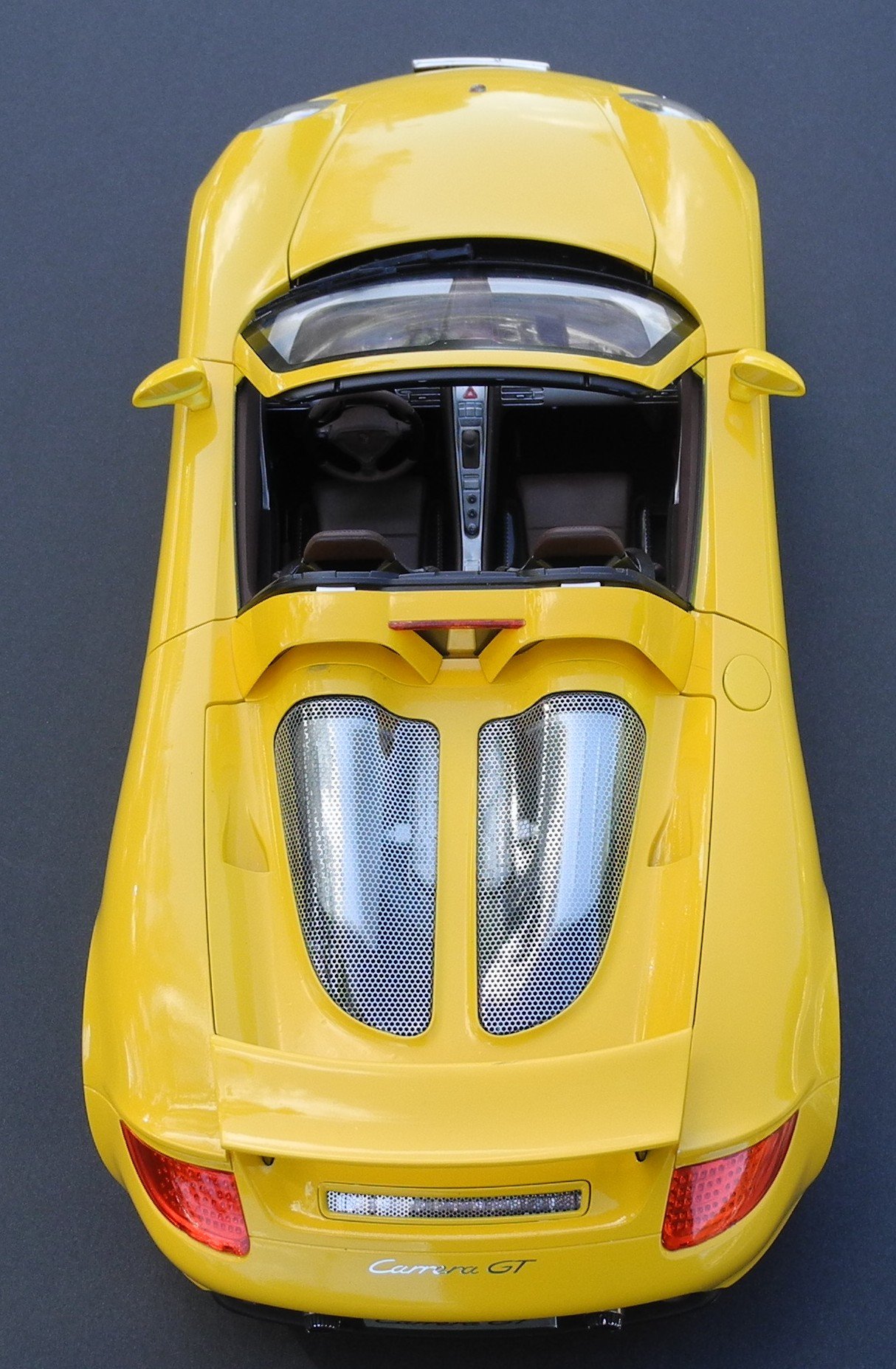
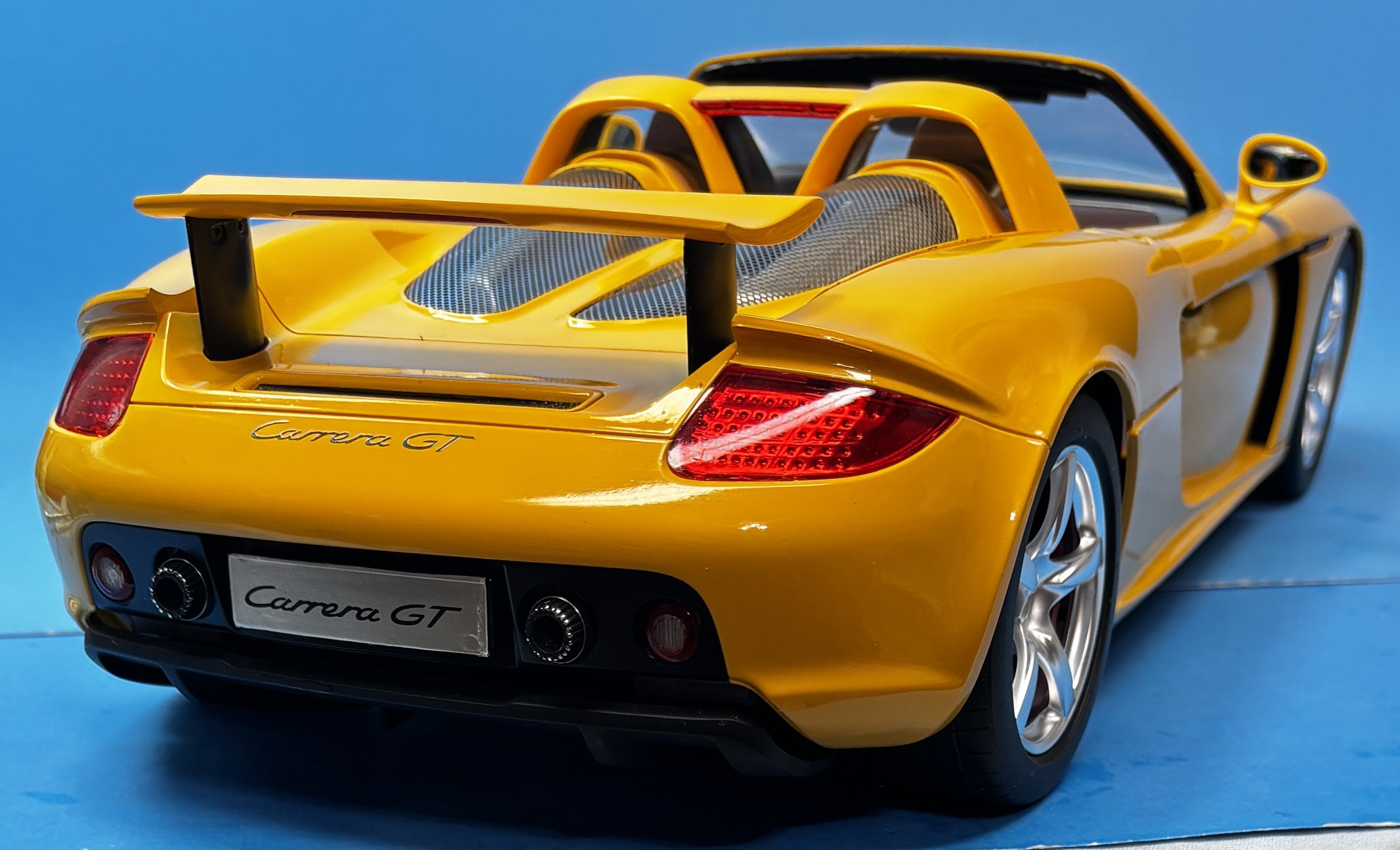
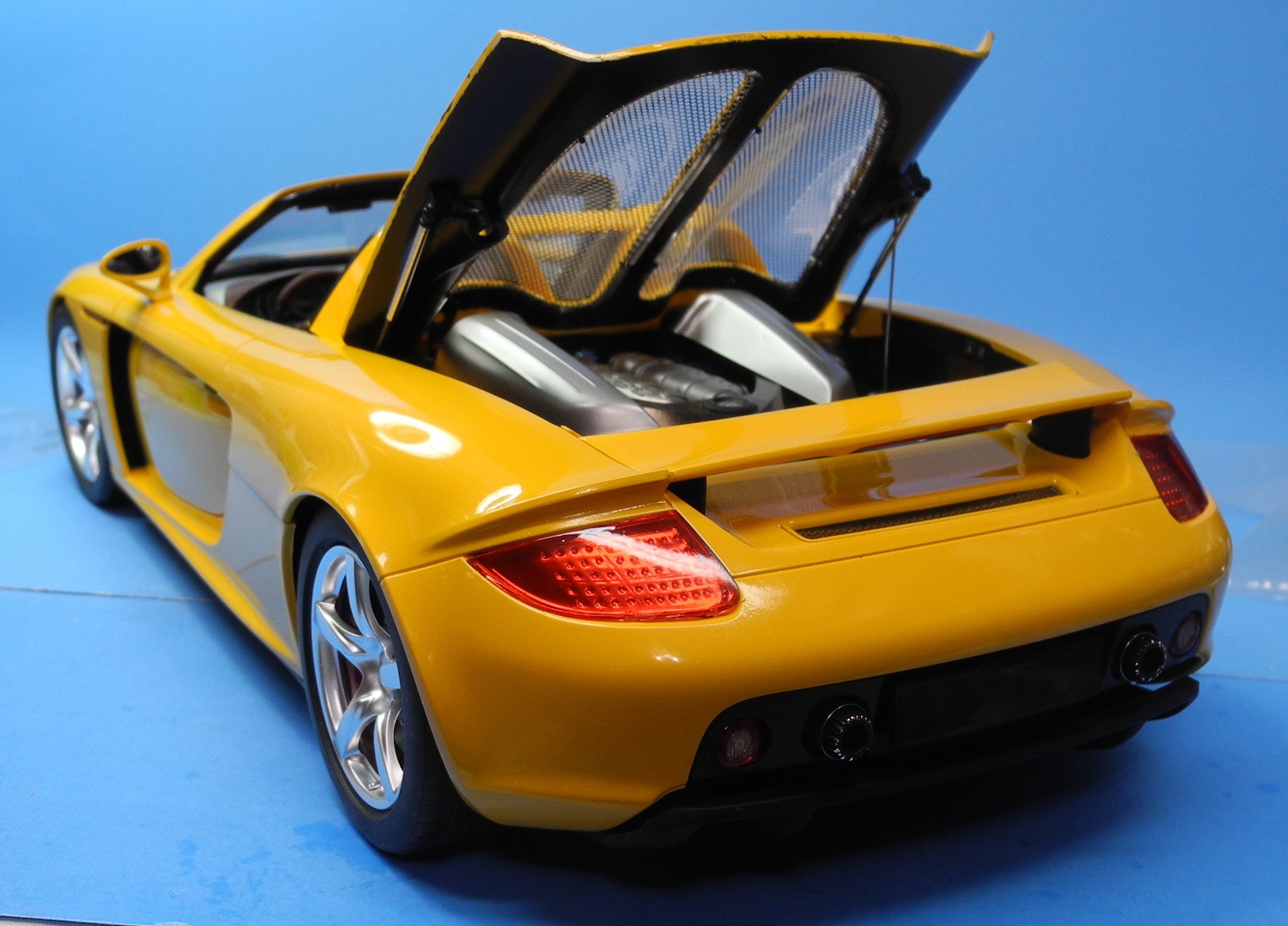
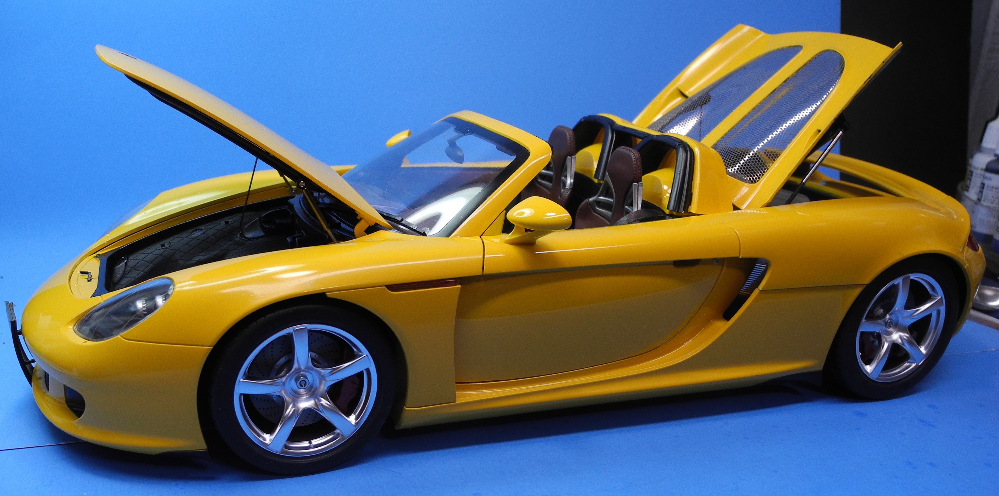
With this model, there is a rather complicated and fiddly geared, spring tensioned mechanism that raises and lowers the rear spoiler. You push it down where it locks into the lowered position, then push on the tag plate to allow it to spring back up to the raised position. In retrospect, I should have left out the internal spring mechanisms and just left it in the lowered position. It's a little over-the-top in my opinion, an unwanted detail,
- Canute, Jack12477, king derelict and 2 others
-
5
-
-
1 hour ago, ccoyle said:
The option is to do no wheel wells -- gear up would require some modification, but I could probably do that without too much difficulty. I can look into it.
EDIT: Gear-up is definitely doable. Doing so would require making a stand, but that would not be difficult.
Either gear up or down is okay with me, I just thought the added issues with wheel wells might be a lot for a 1st kit. I'll follow your lead whichever that is.
-
-
-
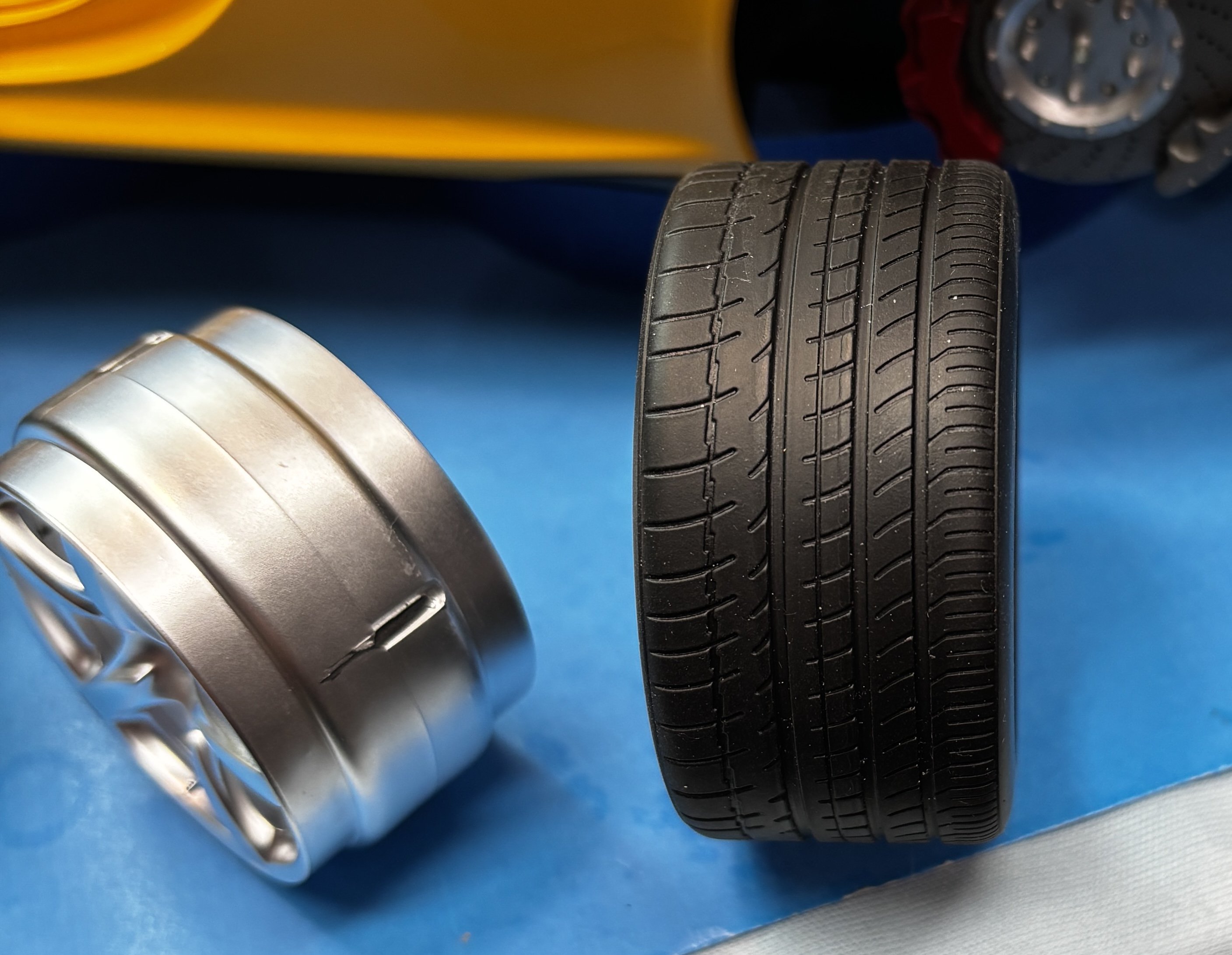
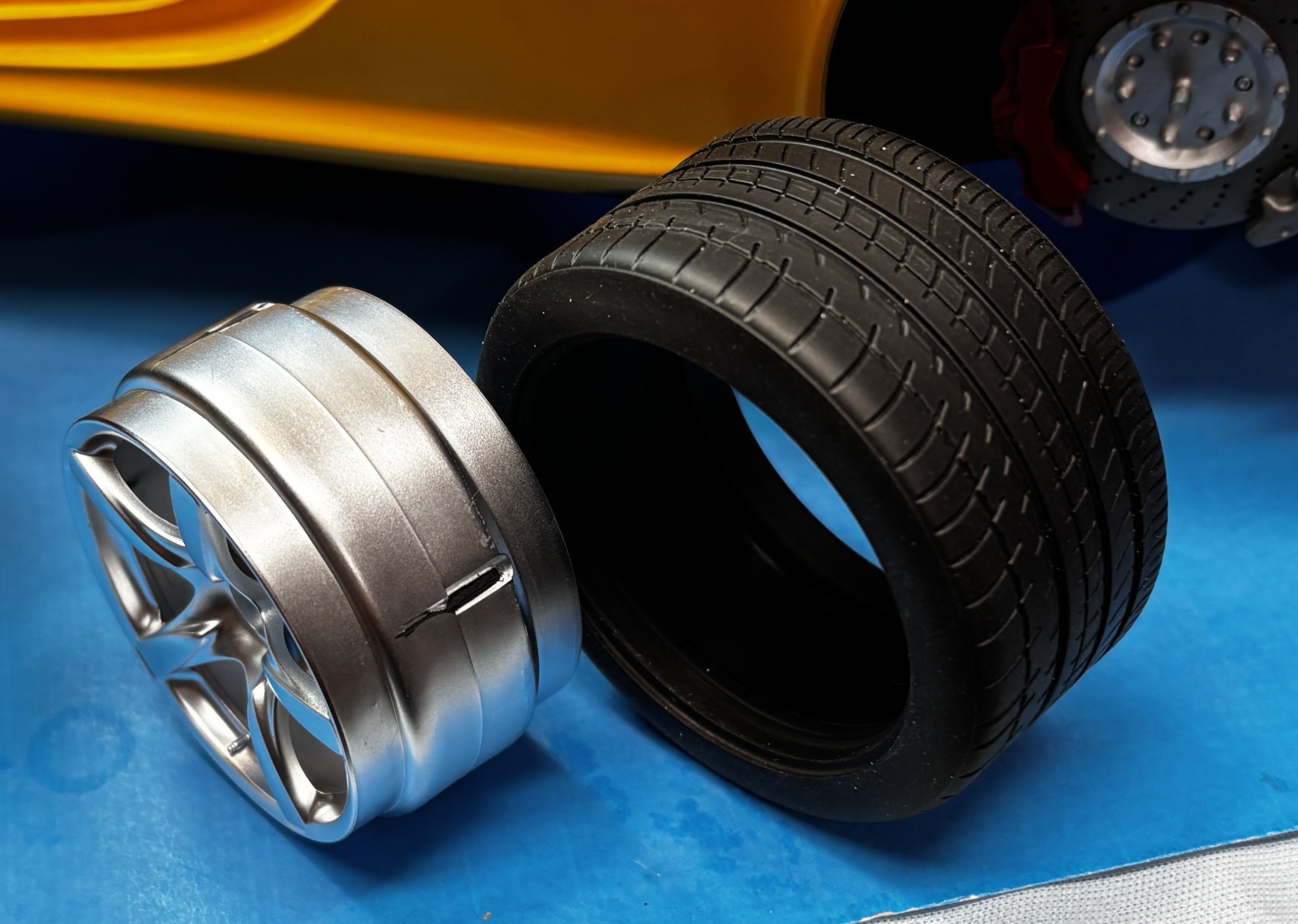
The tires have an inside and outside tread pattern that can be seen in the photo. The way the tire is oriented with the wheel is how they are shown in the photo. The tires and wheels are designed so there will never be a flat spot that develops over time. A tight, solid fit. The finished model is fairly heavy, having a full metal chassis pan.


-
3 hours ago, DocRob said:
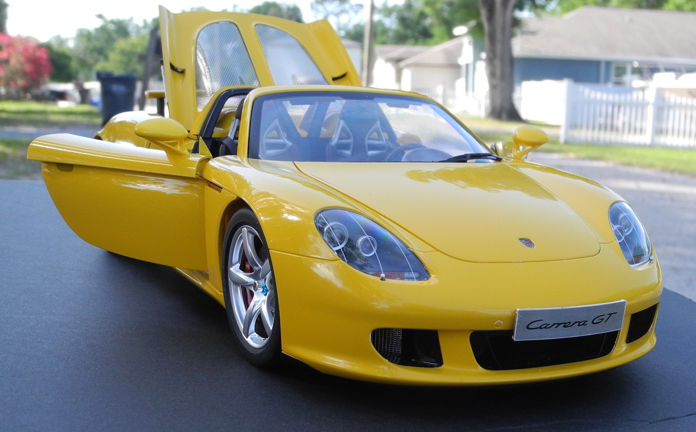
An absolute beauty, Craig. First you convinced me on the yellow and now, I even like the car, you are a magician
 .
.
The interior looks fantastic, absolutely leathery with the stitching and choice of leather color. I can only envy your perfect closing doors, as I couldn´t do it with the Cobra Coupe, even with added magnets and many hours of adjusting.
Cheers Rob
Thank you, Rob. All the great fit and precision can be attributed to the Tamiya tradition of engineering excellence.
By going directly to a vendor in Japan or through Amazon, this kit can be purchased in the USA for less than $300, with shipping included. Through the hobby shops in the States, the prices are well over $500. In my opinion, they are a great value considering the quality of the item.
I still think a MFH kit can turn out much more realistic in many ways, straight from the box, but the demand on the modeler's skill is exponentially greater with a MFH kit. Tamiya simplifies it with their precision engineering.
- Jack12477, Old Collingwood, mtaylor and 2 others
-
5
-
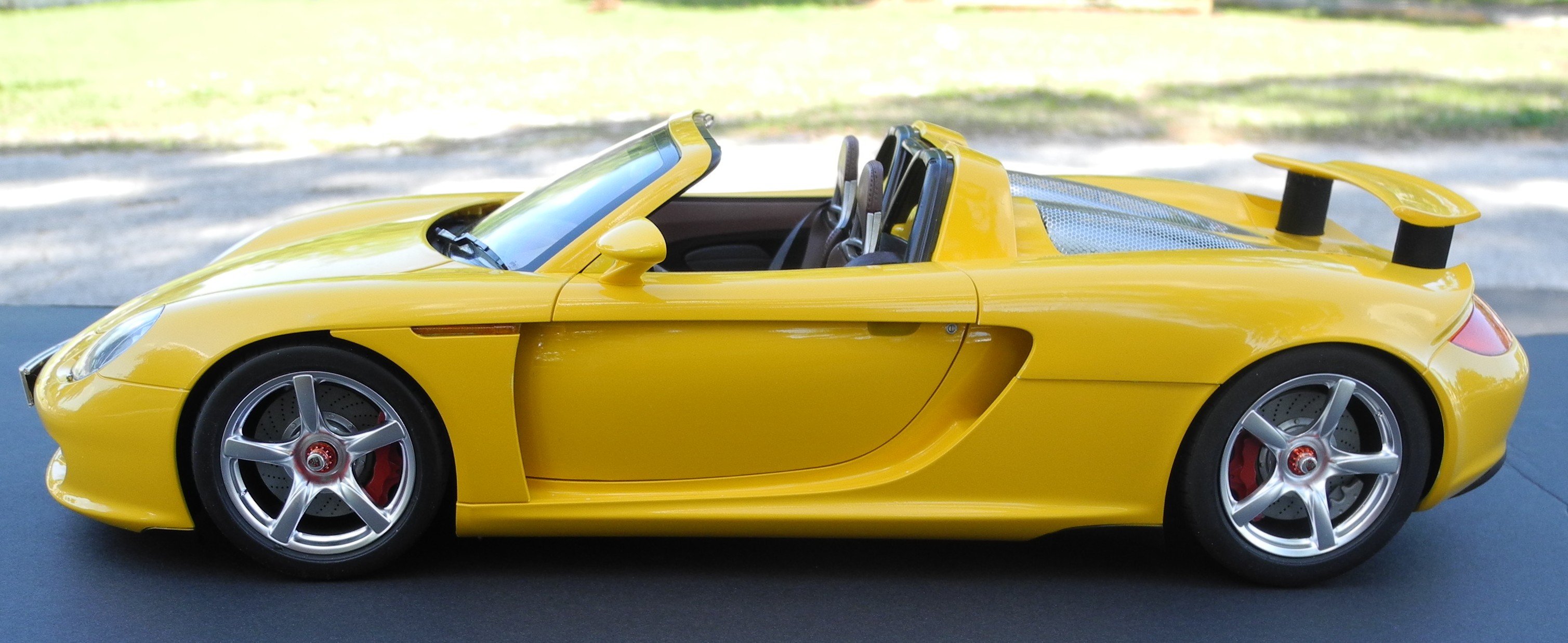
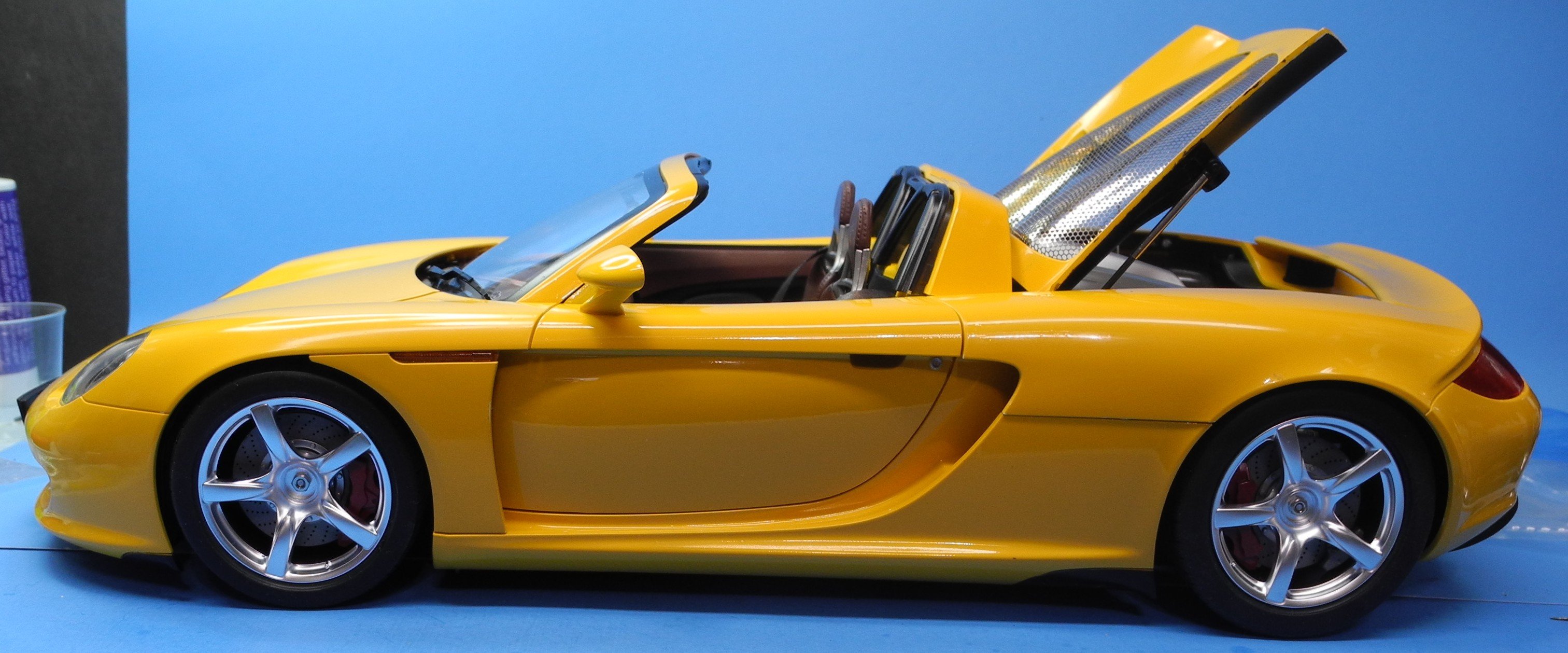
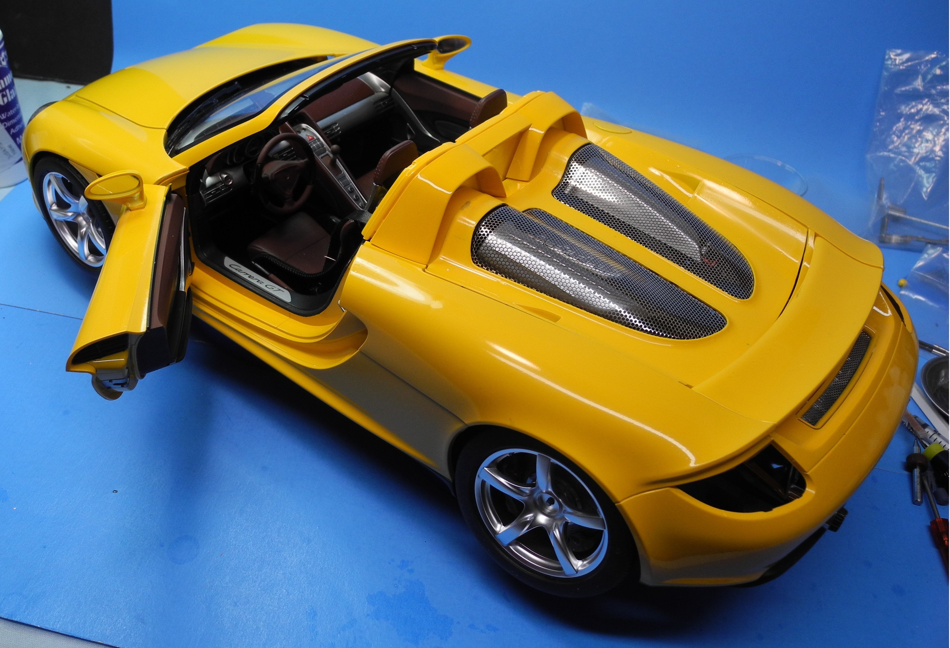
I had to give her a pose from the driver's side with the tires and wheels loosely fitted to this one side.
Tamiya thought of all the details with this model, even the tires are directional. I'll try to take detailed photos of all this and more when I finish the model. Still some more hours need to be spent before calling it done. The devil is always in the details.

-
2 hours ago, king derelict said:
I think I saw one of these (definitely a Porsche) driving down the road a couple of days ago. I think yours looks a lot better
alan
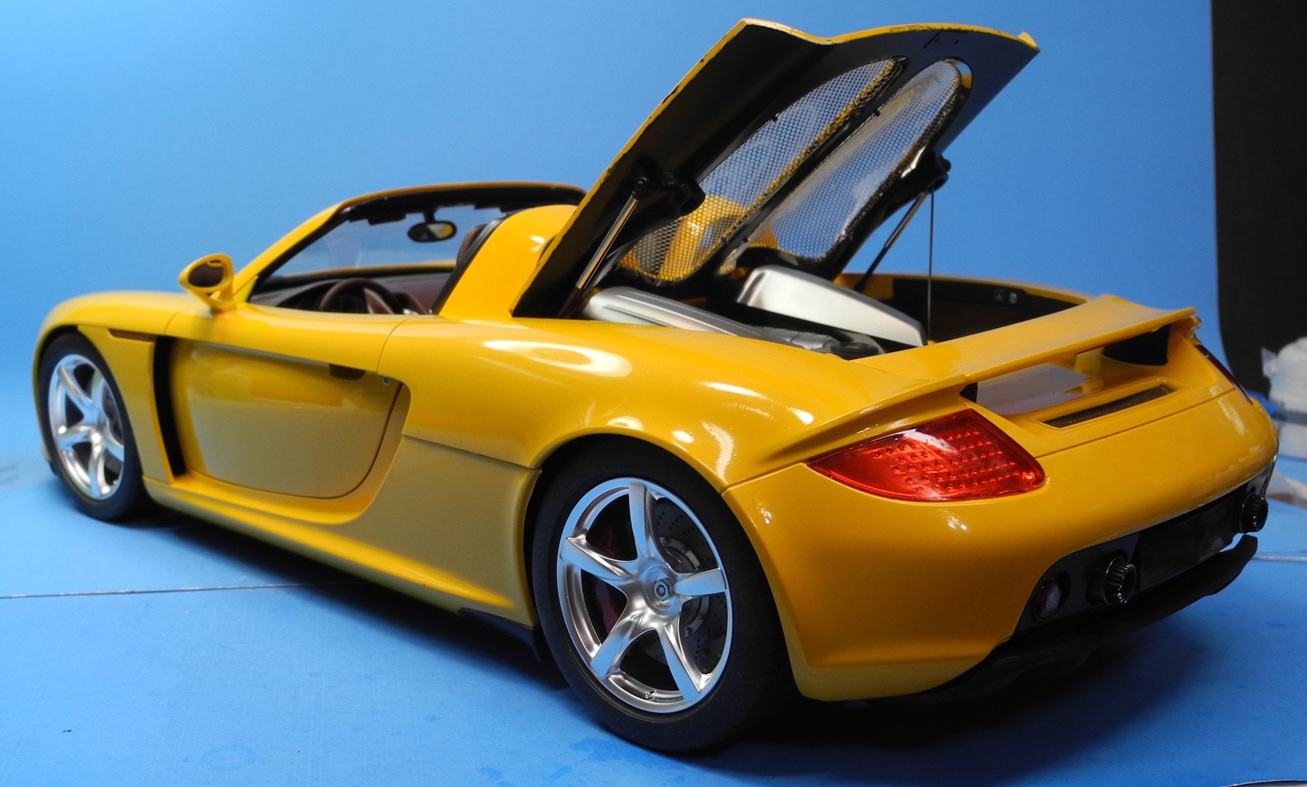
A used 2005 Porsche Carrera GT sells for north of $1,600,000 dollars. Somewhere, I read that the 2010 Carrera GT this car is modeled to represent was twice that price. It's hard to conceive there are people paying that much for a car, but some do. Not many, and a model is as close as I will ever get to owning one.
-
1 minute ago, Jack12477 said:
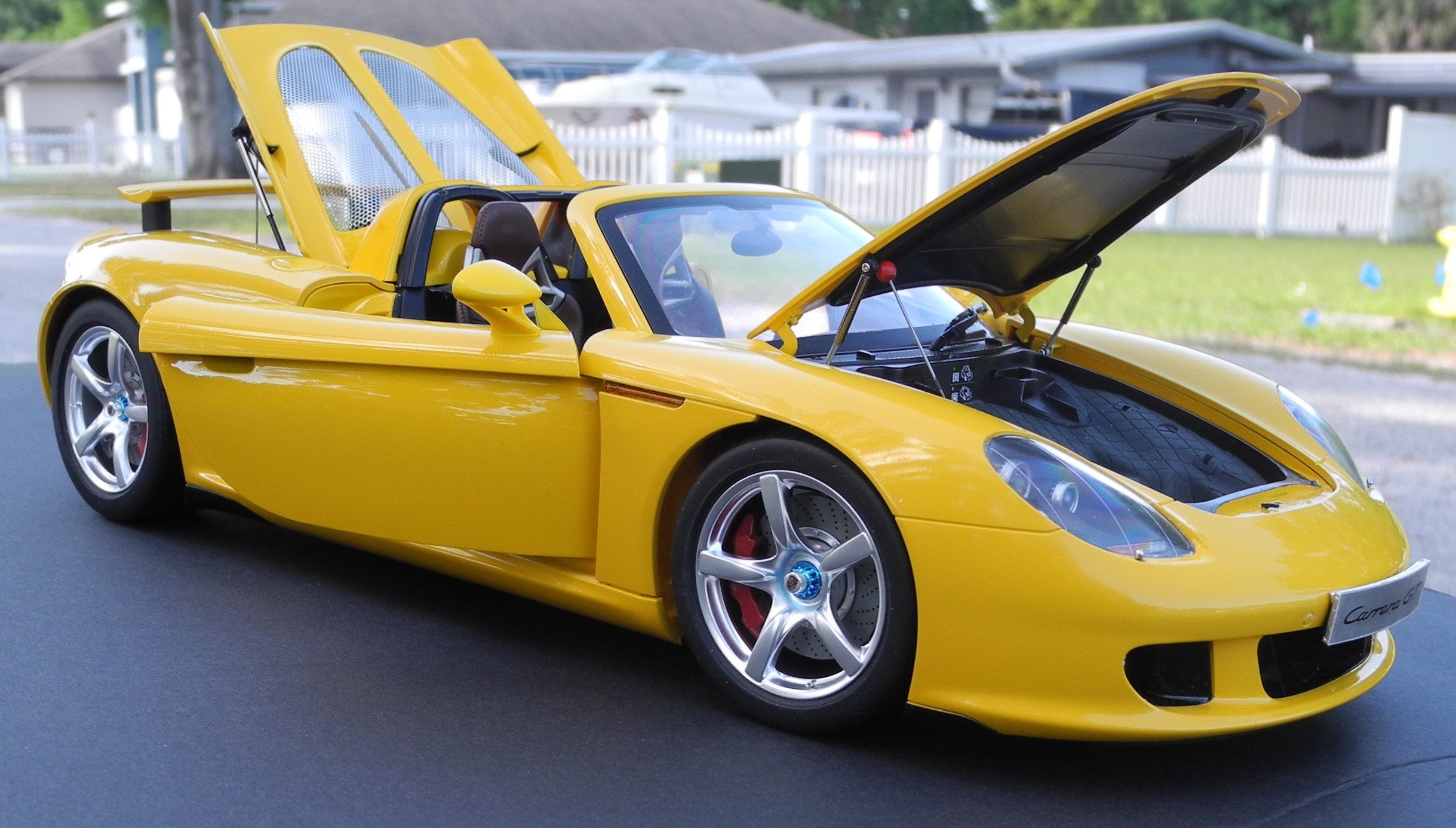
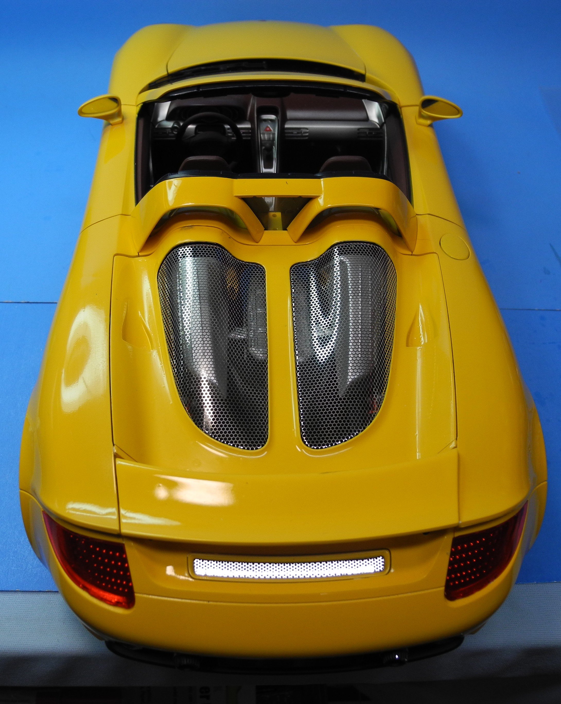
Man, does that shine !
It comes as a result of 8000 and 12000 wet sanding/polishing of the clear coat, followed by a Dremel with a soft wool buffing wheel. Like these sold on Amazon:
- Old Collingwood, Canute, mtaylor and 1 other
-
4
-


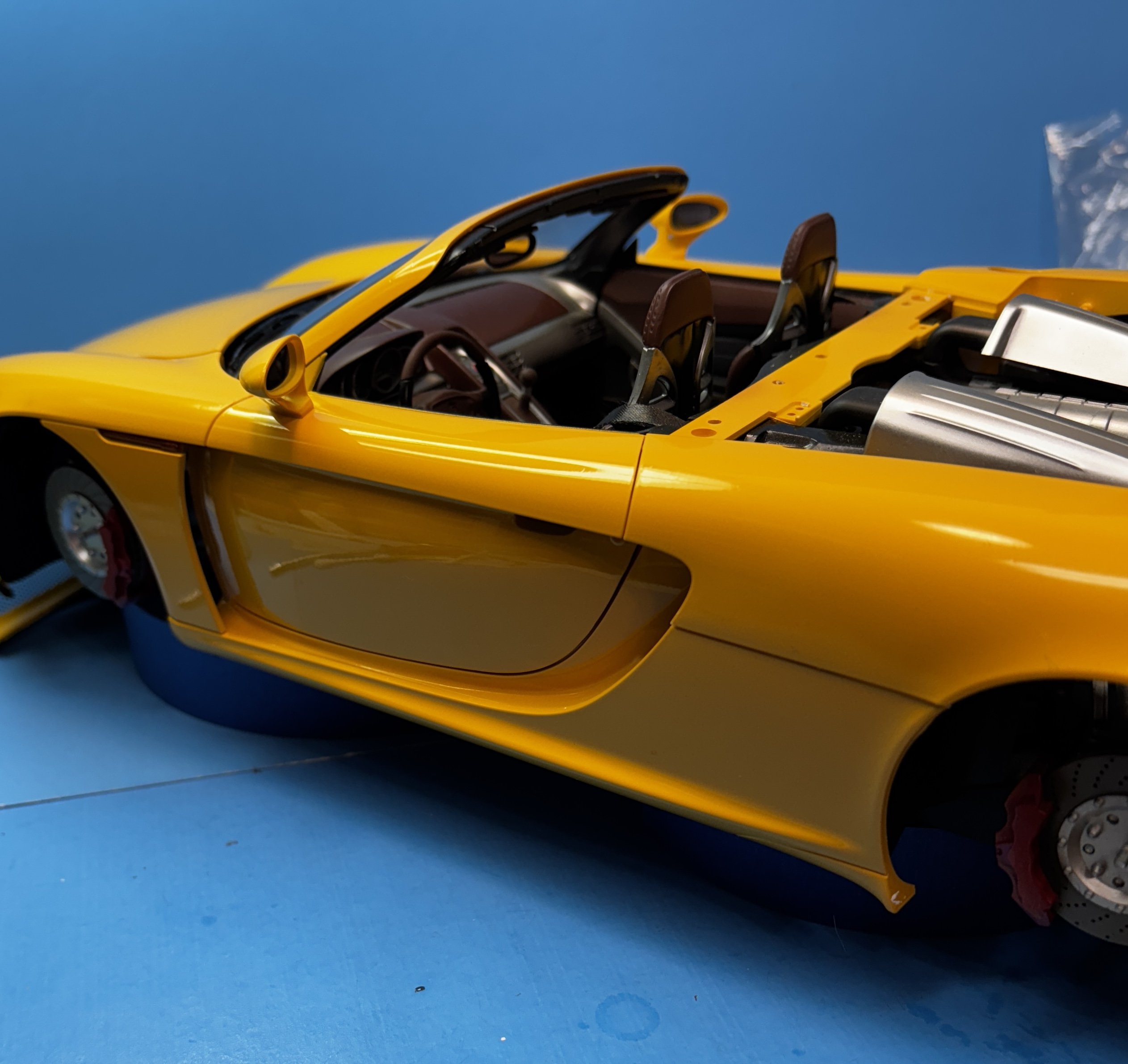
Porsche Carrera GT by CDW - FINISHED - Tamiya - 1:12 Scale - PLASTIC
in Non-ship/categorised builds
Posted
I will enter 3 models in the upcoming Pelicon 2025 IPMS show coming up April 26, 2025. of course, the Porsche Carrera GT is one of the three to be entered along with two motorcycles:
1:12 Tamiya Kawasaki Ninja H2
1:12 Honda RC166 Grand Prix