HOLIDAY DONATION DRIVE - SUPPORT MSW - DO YOUR PART TO KEEP THIS GREAT FORUM GOING! (Only 24 donations so far out of 49,000 members - C'mon guys!)
×


tkay11
-
Posts
1,827 -
Joined
-
Last visited
Content Type
Profiles
Forums
Gallery
Events
Everything posted by tkay11
-
 From memory, I set the cross trees to be parallel to the keel assuming a mast angle of 85 degrees (based simply on the way the mast fitted the slot!). I haven't yet fitted the mast as I'm working on the yards and their rigging. I am not sure a couple of degrees either way would be very noticeable. Tony
- 188 replies
-
- 1
-

-
- Sherbourne
- Caldercraft
- (and 2 more)
-
Just a quickie as I'm on a 30 minute connection in India at the moment. Re the 3-pounders, there is a set of drawings for the Armstrong 3 pounders in the armaments section of the ship modelling resources pages on this site. Tony
- 29 replies
-
- 2
-
-
- sherbourne
- caldercraft
- (and 1 more)
-
Just arrived in Bangalore and have a short spell of internet available. Great to see the progress. Re the 3-pounders, there is a set of drawings for the Armstrong 3 pounders in the armaments section of the ship modelling resources pages on this site. I'll see if I can pop in again later this week. Tony
- 188 replies
-
- 1
-
-
- Sherbourne
- Caldercraft
- (and 2 more)
-
Great to see another Sherbourne build! And, like you, I've just decided on adding sails, so I'm more than interested in your progress. There was a long discussion on MSW1.0 as to whether the Sherbourne might have been clinker built. The consensus at the time was that it might well have been not, but it was agreed that either way would fit the period. It's really up to you -- but no doubt others more knowledgeable than I will chip in with their opinions! I'm sure you'll have noticed Gregor's, Dirk's and Kester's outstanding Sherbourne builds on this forum -- they have lots of good discussion, demonstration, advice and hints. I too have used George Bandurek's book, and found it very helpful indeed -- although my build has differed from his in a few respects. I'll be interested to see what you decide about the topmast and the windlass. I left out the fife rail on mine because of the clutter fore of the mast, but Kester says there are very good reasons for it! I'm not at all a sailor, so I'm probably wrong in that decision! You might want to look at the pictures I took of contemporary cutter models at the NMM at Chatham on this forum as they provide some very interesting details. I'll be travelling for the next three weeks, so may not be able to follow your build until I return. So in the interim, have a good bash! Tony
- 188 replies
-
- 1
-
-
- Sherbourne
- Caldercraft
- (and 2 more)
-
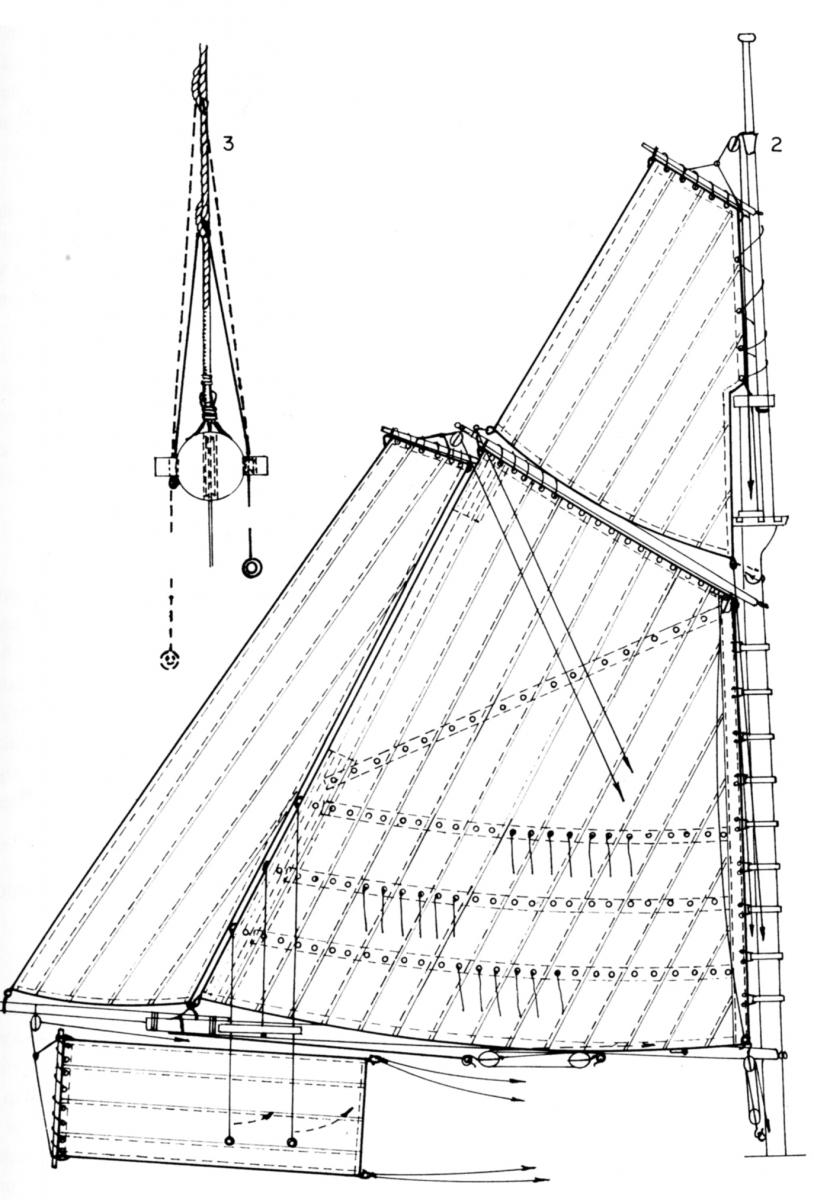
Marquardt in 'The Global Schooner' shows the following as being used for the main sail sheet on page 185: This is very similar to the rig that Petersson shows, although in this case it is for a schooner rather than a cutter. Then on page 176 there is a rather interesting (though quite different) rig described as a 'small topping lift for smaller vessels': I'm showing the latter just as interest! Tony

- 15 replies
-
- 1
-
-
- Cutter
- Sherbourne
- (and 2 more)
-
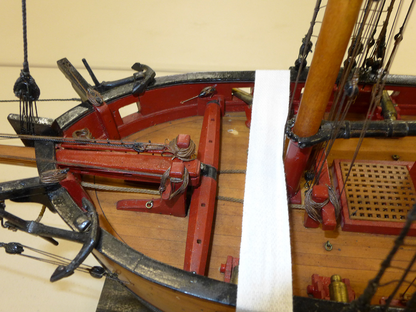
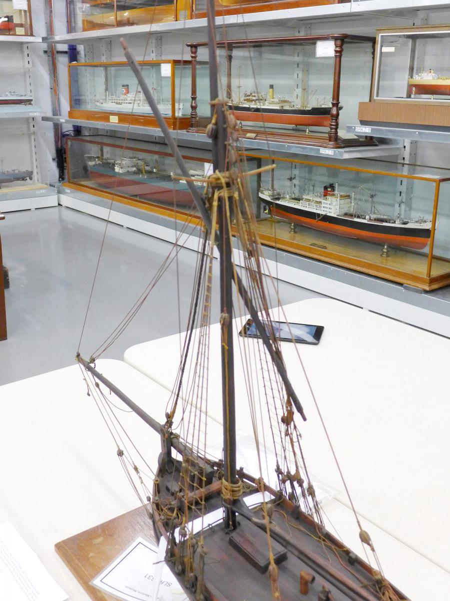
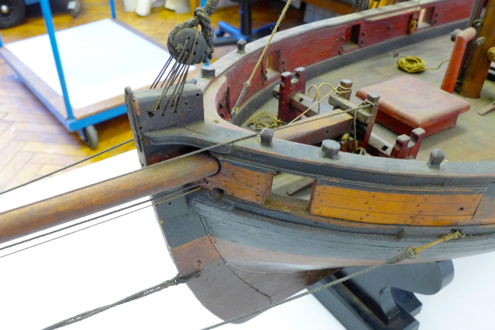
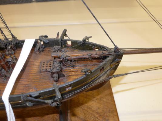
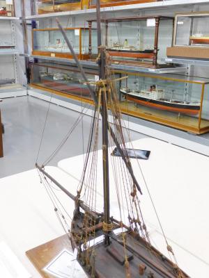
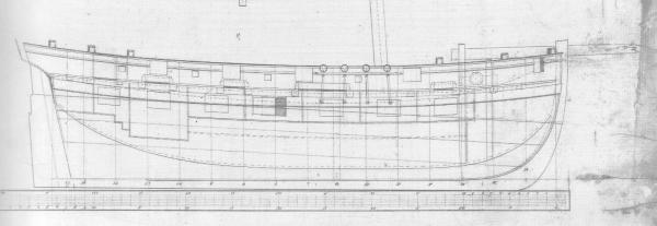
It's a bit late in the game for me, but every time I've looked at my Sherbourne deck recently I've had a nagging suspicion that something is odd. It was this morning when I had another look that it dawned on me. All the cutter models I've seen, as well as the plans in the AOTS book of the Alert by Goodwin and the plans for other cutters, show the bowsprit supports fore of the windlass, and their bitts include the pawl for the windlass. The following are pictures I've taken during my visit to Chatham as well as at the Science Museum store: The following is from Goodwin's book on the Alert: The original plans for the Sherbourne, however, show it aft of the windlass, as is done in the kit: My question is whether this was an oddity, or was it just variable? In mechanical terms I would have thought that having it aft of the windlass would be advantageous in terms of balance and the ease of moving it in or out, but it's clear that a lot of cutter designers seemed to think differently. Having it aft does clutter the deck more, though. Tony


- 1 reply
-
- 1
-
-
- Sherbourne
- 18th century cutters
- (and 3 more)
-
First time rigging - being organized
tkay11 replied to RichardG's topic in Masting, rigging and sails
I too am at that stage, and in general have found the combination of Steel, Biddlecombe's 1848 Art of Rigging, Petersson, zu Mondfeld, some rigging tables from the forum's database, a visit to Chatham to look at 18th-19th century cutters, and numerous contributors on this forum to be the most useful. My own decision was not to go for rope (other than for seizing) less than 0.25mm, and then to restrict myself to observable differences. So I've ended up making rope of 0.25, 0.4, 0.5, 0.7 and 1.0 -- apart from the anchor ropes which will be made from one of those. Then I went through Petersson and by using Biddlecombe's tables, listed each rope to the nearest size of my thread in a spreadsheet table (which automatically converts the original circumference sizes in inches to mm at 1/64). I added to my table the blocks that would be connected to the ropes, defining them by the rope sizes, using the spreadsheets I mention below of zu Mondfeld's tables for block sizes. As with the ropes, I've decided on only a few block sizes, going for the smaller option when available. Thus I have 3mm, 4mm and 5mm blocks in single, double and triple sizes. You'll find a very handy set of spreadsheet tables for the sizes by Jim Lad <Period Ship Scale Tables.xls> as well as Biddlecombe's book in the Ship Modeling Database of this forum. There also used to be two spreadsheets on the old forum (MSW1.0) before the crash called <Rigging rope sizes metric V2.03.xls> by Bev Armstrong (which allows you to specify the period of your ship and the rope diameter steps you prefer) which converts using zu Mondfeld's data, and <Rigging.xls> by Peter Jaquith which is a rigging line and block conversion table allowing you to input the scale of your model to establish the scaled diameter of rope and the ensuing blocks in both mm and inch dimensions. I have both of these latter tables and can send them to you by PM if you'd like. Armed with all this, the advice given above by the others in their replies above sounds great. I've found that as with all the other steps in making a model so far, the best approach is a step at a time, making sure you understand the function and the potential ways of making it as fully as possible, and you'll find that all of a sudden you're looking back at something you thought would be next to impossible before you started. After having been daunted, like you, with the new terminology and complexity of rigging, as well as the different ways in which the same piece of rigging can be described, I've now completed my bowsprit rigging and about to venture to the uncharted territory of masts and yards. This time not with dread, but with interest and excitement at the thought I may actually be able to do it! Best of luck! Tony -
Thanks, everyone, for the rich detail. These are the kinds of explanation that make the making of a model more deeply satisfying and interesting. I can certainly see that what I was calling 'bees' are in fact turning blocks -- the small point opposite each one implies a sheave. Interestingly, none of the 5 cutter models I saw at Chatham (see the discussion at http://modelshipworld.com/index.php/topic/10370-18th-and-early-19th-century-cutter-models or in the Gallery) had either the tackle or the turning blocks, even though it seems from this discussion that they are quite normal aspects of sailing. Tony
-
Thanks, Tadeusz and Spyglass. That's the very one! It shows I have a lot more to learn about sails. That was very helpful indeed! Tony
-
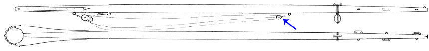
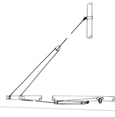
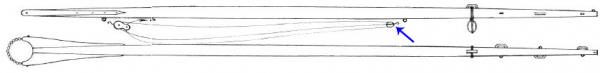
In his book on Rigging Period Fore and Aft Craft, Petersson shows a diagram of a boom as follows: The arrow I have added shows some tackle fitted to the underside of the boom, quite separate from the mainsheet tackle (which is given the honour of a full diagram later), but there is no other mention in the book or diagram of how this might be used. I'd be very grateful if someone could explain it to me or give me some idea of its function and the points to which it might be fixed. Oh, and by the way, I'd also be glad of some explanation of the function of the bees at the end of the boom as displayed (just to grab as much info as possible in one swoop!). Thanks in advance for any ideas Tony
-
Interesting about the US eBay. I looked it up for the UK and it's on the UK eBay site too, ref 311275446173, for £21.97 plus £4.35 p&p in the UK. Tony
-
Just want to say, Dan, that I've used this method of yours for cleats (after your posting on cleats) and it's such an elegant solution for consistent width and height of small pieces. Thanks a lot! Tony
-
For the difference between ship's and french curves, see the discussion at http://forum.woodenboat.com/archive/index.php/t-13329.html. Tony
-
18th and early 19th Century cutter models
tkay11 replied to tkay11's topic in Nautical/Naval History
Thanks for the thought, Kester. I was also wondering whether, when they increased the length of the topmast (perhaps with a view to supporting wider or more yards) they found the need for backstays and therefore that the more logical position would then be aft. Tony- 42 replies
-
- 2
-
-
- Cutter
- 18th Century
- (and 4 more)
-
18th and early 19th Century cutter models
tkay11 replied to tkay11's topic in Nautical/Naval History
Sorry, Alex, but I simply don't know as I didn't ask -- although I was told that some of the rigging was done in the museum as a repair. Tony -
18th and early 19th Century cutter models
tkay11 replied to tkay11's topic in Nautical/Naval History
Thanks, Kester. I'd noted that you'd said that before in your build log (I think), but I don't understand why the position of the topmast fore or aft would change its need for a backstay since it seems firmly embedded at the cross-tree and the top either way. This is simply my lack of understanding so it would be great if you could explain more. Sorry for the ignorance but I'll benefit from an understanding! Tony -
Good to see another Sherbourne builder -- and in the UK too! I'm much looking forward to the rest of the build. You've made a good start with nice planking. I too made the mistake of leaving the stern on and scratching it -- as have a few others. It was only after reading some of the logs that I learned how to avoid the problem. Welcome to the Sherbourne MSW club! Tony
- 18 replies
-
- 4
-
-
- sherbourne
- caldercraft
- (and 1 more)
-
18th and early 19th Century cutter models
tkay11 replied to tkay11's topic in Nautical/Naval History
Thanks, Kester. Nice comments. I agree that the Sherbourne's mast is not incorrect. It's just that I think that even at that time there was a choice (as evidenced by the model). As I've explained in the recent update on my Sherbourne build, I've gone with the Petersson version where the topmast is fore because his rigging is easier for me to do (I think), as well as because I think it gives better positioning for the peak and throat halliards. However, because I have never sailed, and am unclear about the mechanics, I simply don't know the advantages and disadvantages of the different possible positions of the topmast. As to the braces running aft, I'll wait to hear the other comments as again I simply don't know the ins and outs! Tony- 42 replies
-
- 1
-
-
- Cutter
- 18th Century
- (and 4 more)
-
18th and early 19th Century cutter models
tkay11 replied to tkay11's topic in Nautical/Naval History
Matt, I'm a real novice and have never sailed, so I can't answer your questions. But I'm sure the more learned here will soon be chipping in! Tony- 42 replies
-
- 1
-
-
- Cutter
- 18th Century
- (and 4 more)
-
18th and early 19th Century cutter models
tkay11 replied to tkay11's topic in Nautical/Naval History
Thanks for the suggestion, Chuck. I've uploaded all the photos to the gallery of contemporary models as requested. When doing this, I didn't understand the box beside each photo which said 'Follow Image'. Could someone explain? Tony- 42 replies
-
- 4
-
-
- Cutter
- 18th Century
- (and 4 more)
-
18th and early 19th Century cutter models
tkay11 replied to tkay11's topic in Nautical/Naval History
The only ones that don't have obvious fids/holes for the fid are the Trial and the 12-gun cutter. However it looks as though they, like the class, are set up to have sliding bowsprits. I'd also noticed the loop on the stay and agree it might be something I do! Tony- 42 replies
-
- 2
-
-
- Cutter
- 18th Century
- (and 4 more)
-
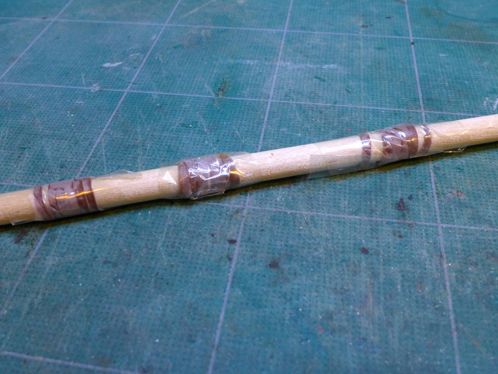
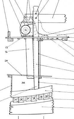
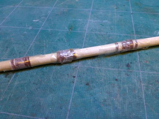
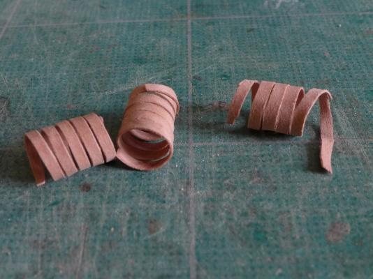
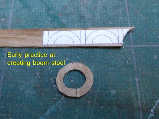
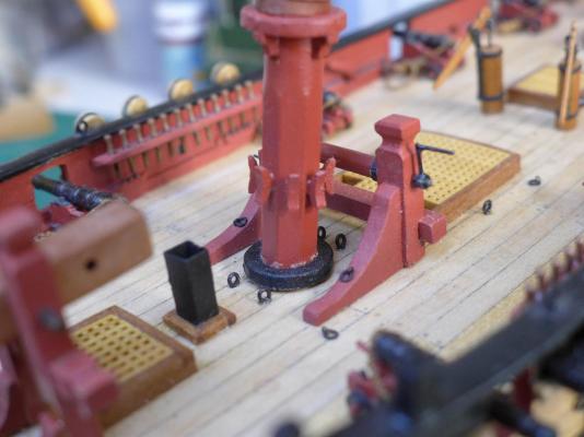
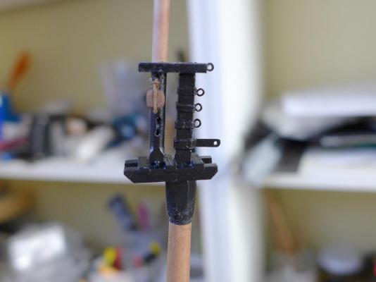
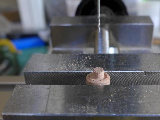
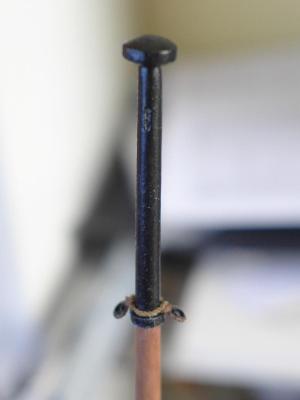
MAIN MAST One of the tricky questions to answer was whether to place the top mast fore or aft of the main mast. The Alert AOTS book by Goodwin suggests placing it aft, as do the instructions and plans in the Sherbourne kit. Kester has followed this on his model and backed it during our discussion on whether or not to have topmast shrouds (http://modelshipworld.com/index.php/topic/8622-topmast-shrouds-for-sherbourne/) where he said the following: “I am not certain that Sherbourne was actually rigged with topmast backstays, which is probably why they are not shown on the plans (and seemingly something they have got right!). “The cutter shown in Petersson's 'Fore and Aft Craft' is based on the model in the Science Museum (or was), which I believe dates from around 1785. Earlier cutters, which of course included the Sherbourne, don't seem have had them due to the positioning of the topgallant mast, abaft the lower mast head. This was thought sufficient support, and thus they were not necessary. “Goodwin mentions this in his AOTS book on the Alert and goes on to say that topmast backstays were introduced later (around the 1780's), when the topgallant mast began to be stepped on the fore side of the lower mast head. The length of the upper mast was also lengthened which made them even more necessary. Even then, however, they don't seem to have given much support from aft. In the book, there is a drawing of the Alert on page 104, which shows a ticked line indicating a breast backstay, ie. on each side of the topgallant mast, but he stresses this may or may not have been fitted.” Initially I was going to go for this placement as well, but following my visit to Chatham (http://modelshipworld.com/index.php/topic/10370-18th-and-early-19th-century-cutter-models/) and seeing the 1763 cutter rigged with the topmast forward of the mast head, I decided to go with the rigging plan provided by Petersson. One of the things in the back of my mind was the placing of the throat and peak halliards, which are given extra height by being attached to the back of the mast head. Another thought was that as I am a complete novice I felt more comfortable going for the detailed rigging plan provided by Petersson. At least there’s some kind of logic there! So, after studying the dimensions of masts in Steel and Biddlecombe, I made some square pear stock and planed it with a David plane to an octagonal. I left the mast octagonal from the heel up until just below where the stool for the boom is placed. This also allowed for neat placing of the cleats that go around the base of the mast. I also left the mast octagonal at the hounds at the mast head. Otherwise, as with the bowsprit, I dimensioned the mast using the lathe and sanded it down. MAST HOOPS After fiddling around with offcuts from the planning I had done on the masts I gave up and instead cut a 0.3mm slice of pear which I then cut into 1.7mm widths, soaked in water and wrapped around a dowel of the right diameter. This was then wrapped in cling film for an hour or so, then I had mast hoop material ready for cutting and gluing: You can see the finished hoops in the picture that follows under the heading ‘Cleats’. BOOM STOOL The AOTS book on the Alert shows a stool for the boom at the base of the mast. These stools were also on the cutters I had seen at Chatham. I made one by using the mast diameter to draw circles of the correct diameter using TurboCAD. These circles were then halved and pasted onto pear strips. The following picture shows an early experiment. The final result is shown in the picture of the base of the mast in the following section on ‘Cleats’. CLEATS Instead of using the large cleats provided by the kit, I made them following Dan Vad’s method which you can see at http://modelshipworld.com/index.php/topic/230-hms-vulture-by-dan-vadas-1776-148-scale-16-gun-swan-class-sloop-from-tffm-plans/?p=305401 This method is really elegant in that it ensures an even width and length for the cleats. The only problem was positioning them at equal heights around the base of the mast. I drilled holes through their centres and passed 0.4mm copper wire through them, which I then glued with epoxy into holes drilled in the mast as follows: After cutting off the ends of the wires and painting the lower mast, it looks as follows: Please note that the base of the mast is not yet finished, hence the sanding marks at its base. MAST HEAD [EDIT: As a matter of interest to those interested in forward planning, I discovered too late that it would have been very handy not to have fitted the top mast and the top cap before adding the shrouds. If I had not fitted the top mast and cap, it would have been much easier not only to tie the shrouds very easily, but also to fit the two sets of pendants (mast tackle and back stay) in the correct manner.] Although Petersson shows a sheave at the top of the mast head, I followed Goodwin in placing an eyebolt at the top which holds a block. This in turn links to the sheave at the bottom of the topmast for the toprope. Please note that I should have placed the sheave lower at the bottom of the topmast in order to give more room for the mast to be lifted under the block. Just to pre-empt those who demand I replace it, I am not going to do it on this model as I want to get on with the rest of it! A fid was placed in the heel of the topmast and another sheave drilled at its top for the topsail yard halliard. Eyebolts were placed at the back of the mast head for the topping lift and the throat and peak halliards. TOPMAST I made a top on the lathe and glued it to the topmast after drilling holes for the sheave for the pendant halliard. I then made a pair of thimbles for the topsail lifts in the same way as I made the thimbles for the bowlines at the bowsprit. Now to start the business of making the remaining masts and more rigging. Tony


- 269 replies
-
- 5
-
-
- Caldercraft
- First build
- (and 3 more)
-
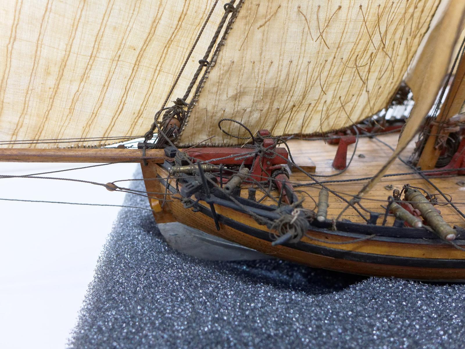
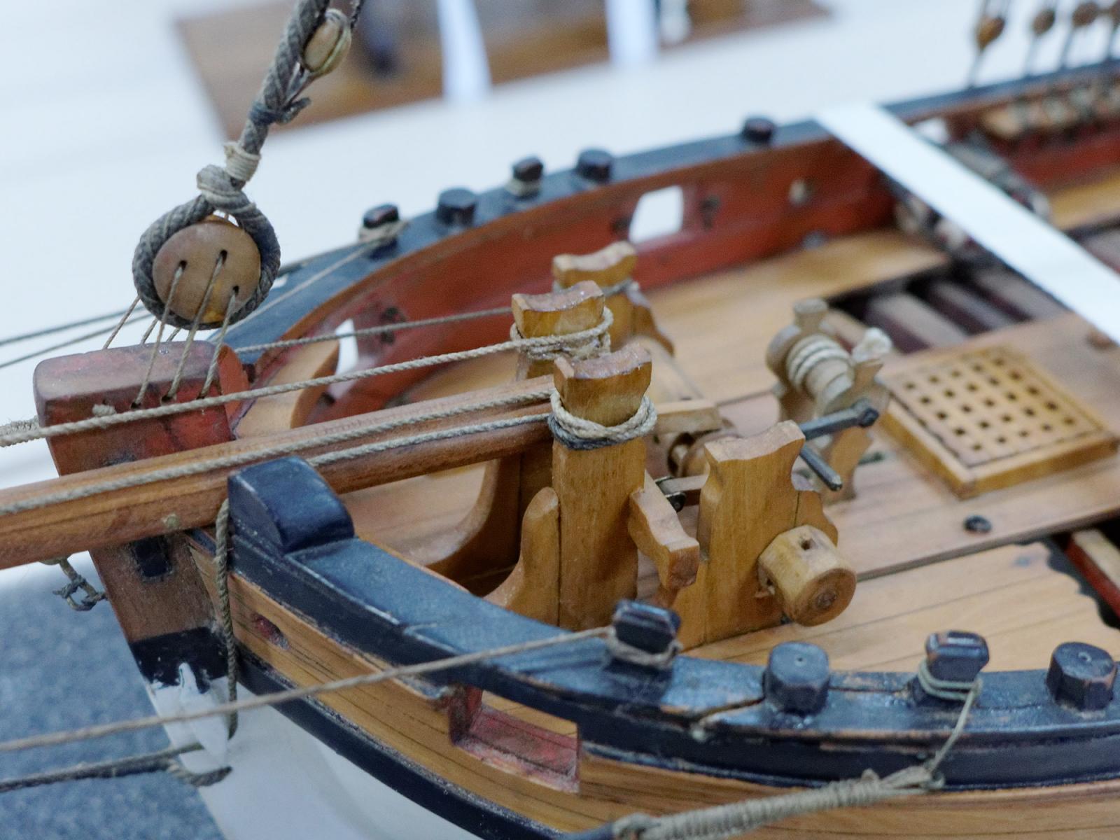
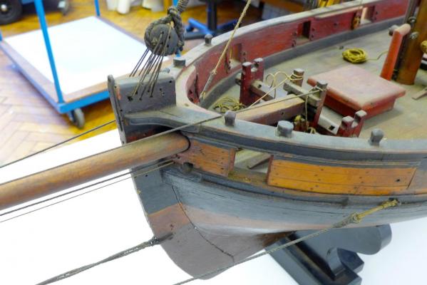
BELAYING PINS AT BOW Following my visit to Chatham, which I described at http://modelshipworld.com/index.php/topic/10370-18th-and-early-19th-century-cutter-models/ I decided to change the belaying pin rack at the bow. Gregor, Dirk, Kester and myself have had different approaches to this, but two of the models I saw had their racks positioned fore-aft beside the bowsprit and linking to the pawl post. I therefore decided that this was a really neat solution, dismantled the belaying racks I had made and replaced them as follows: You’ll see pictures of the contemporary models with this arrangement at the posting I have given above. Next up: the main mast Tony
- 269 replies
-
- 7
-
-
- Caldercraft
- First build
- (and 3 more)
-
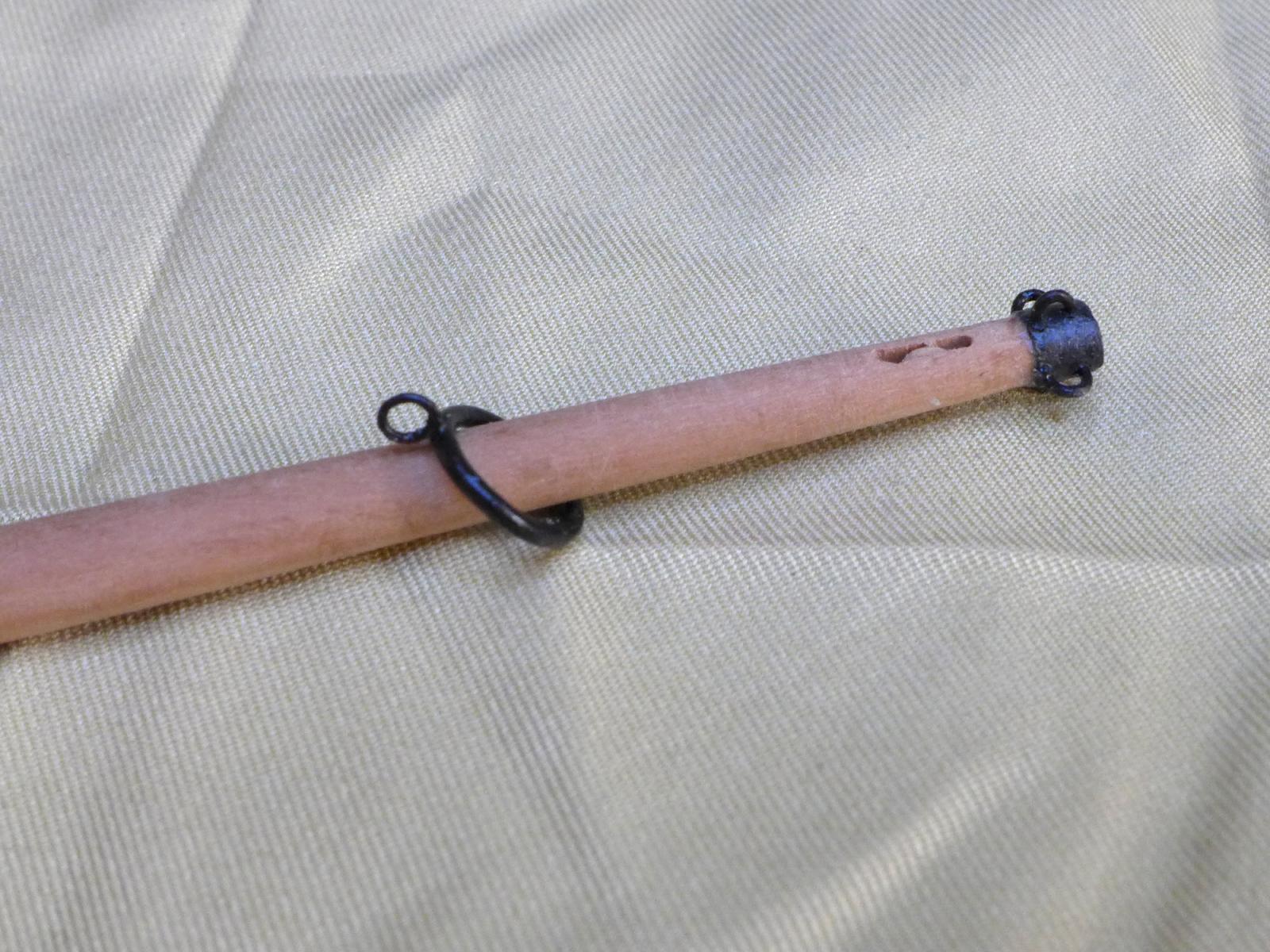
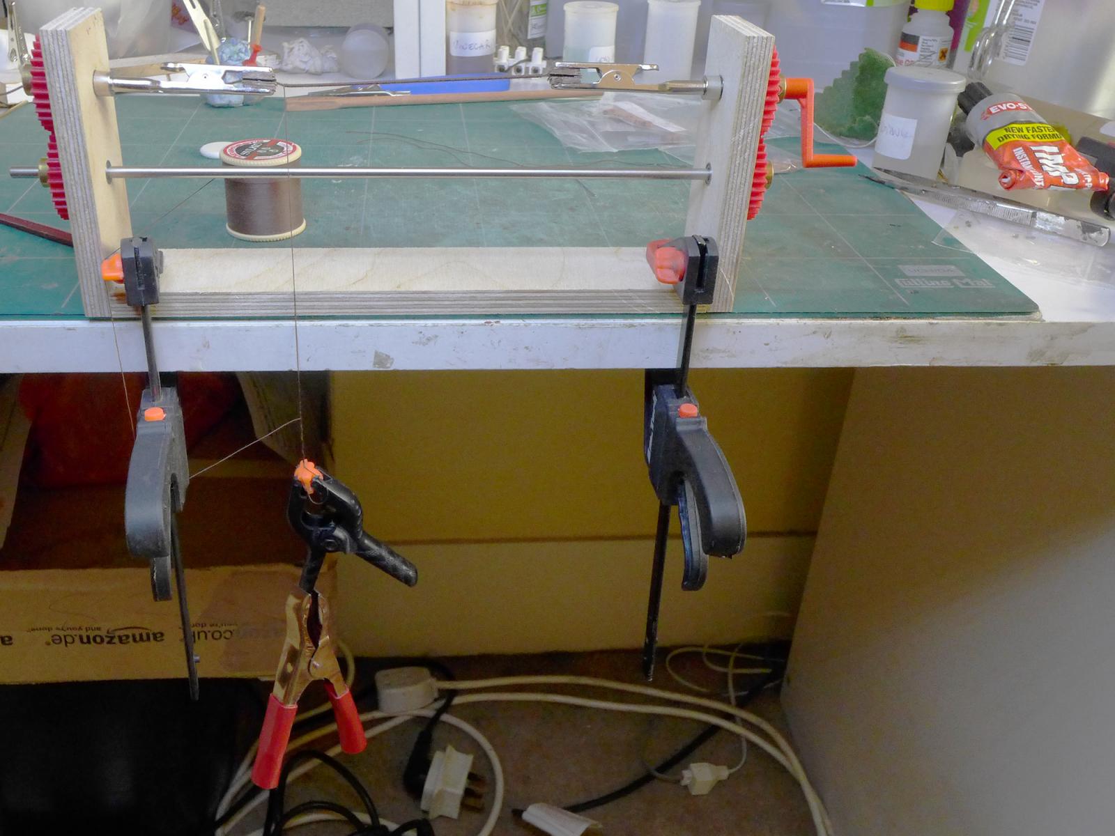
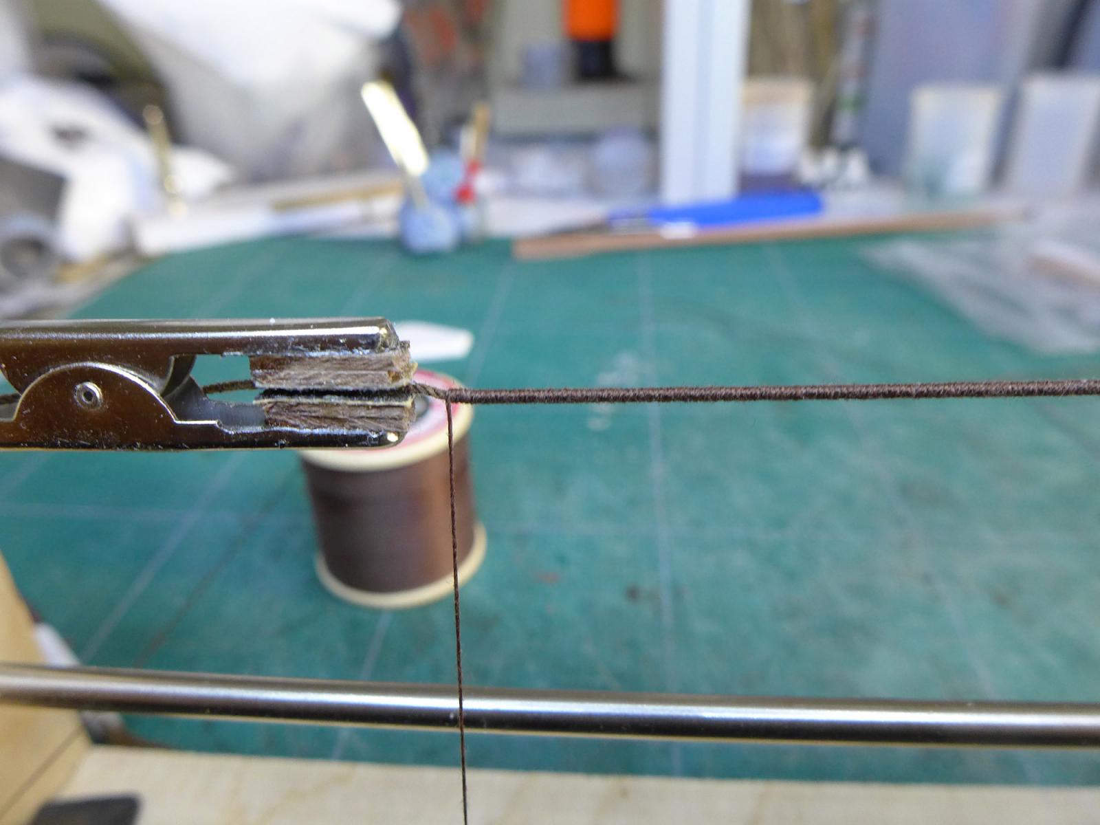
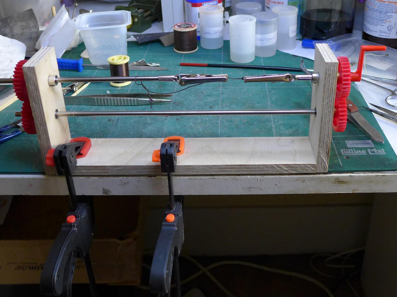
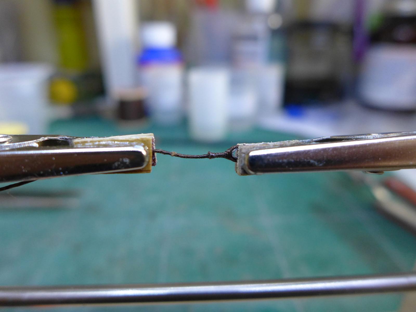
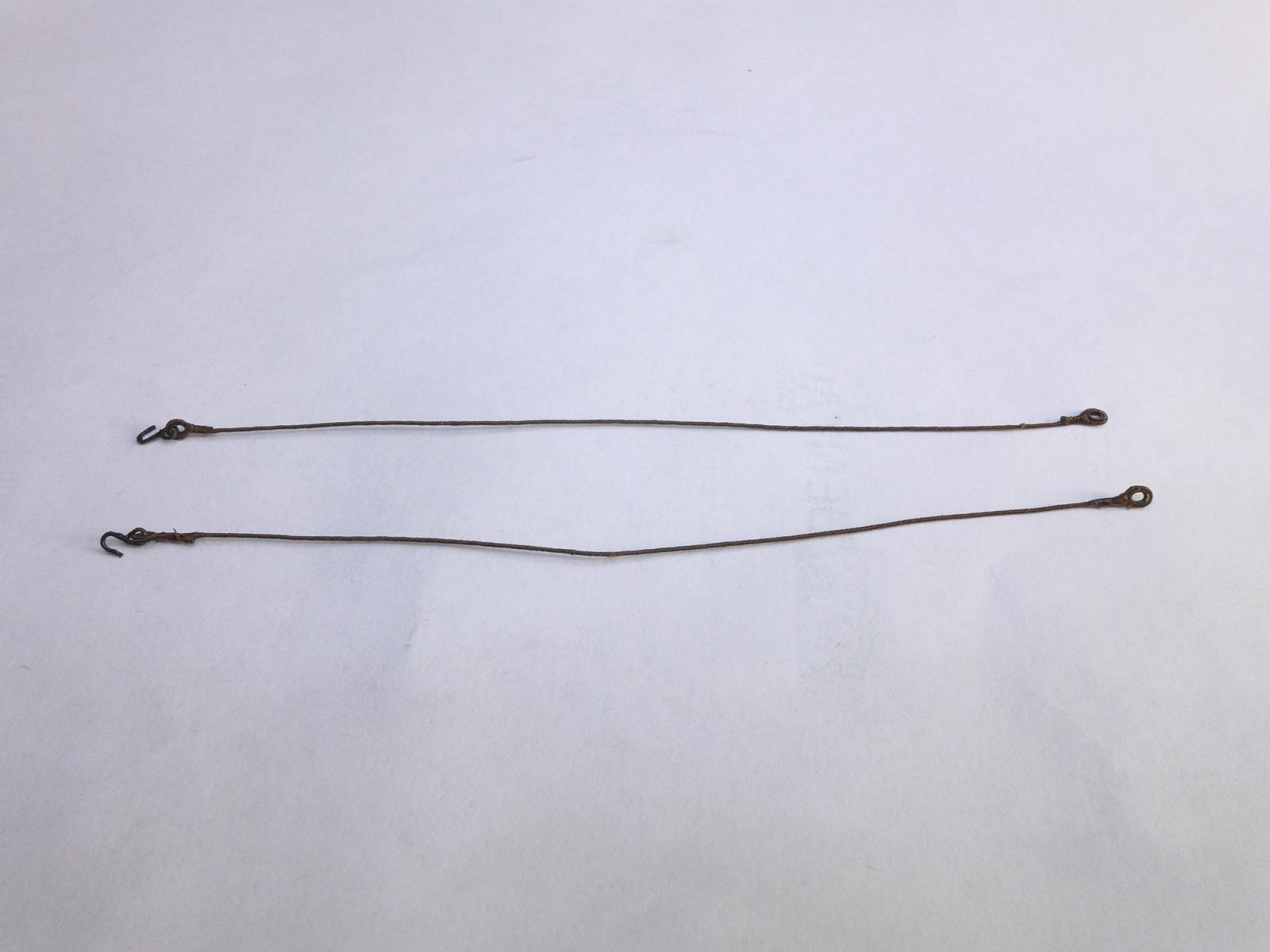
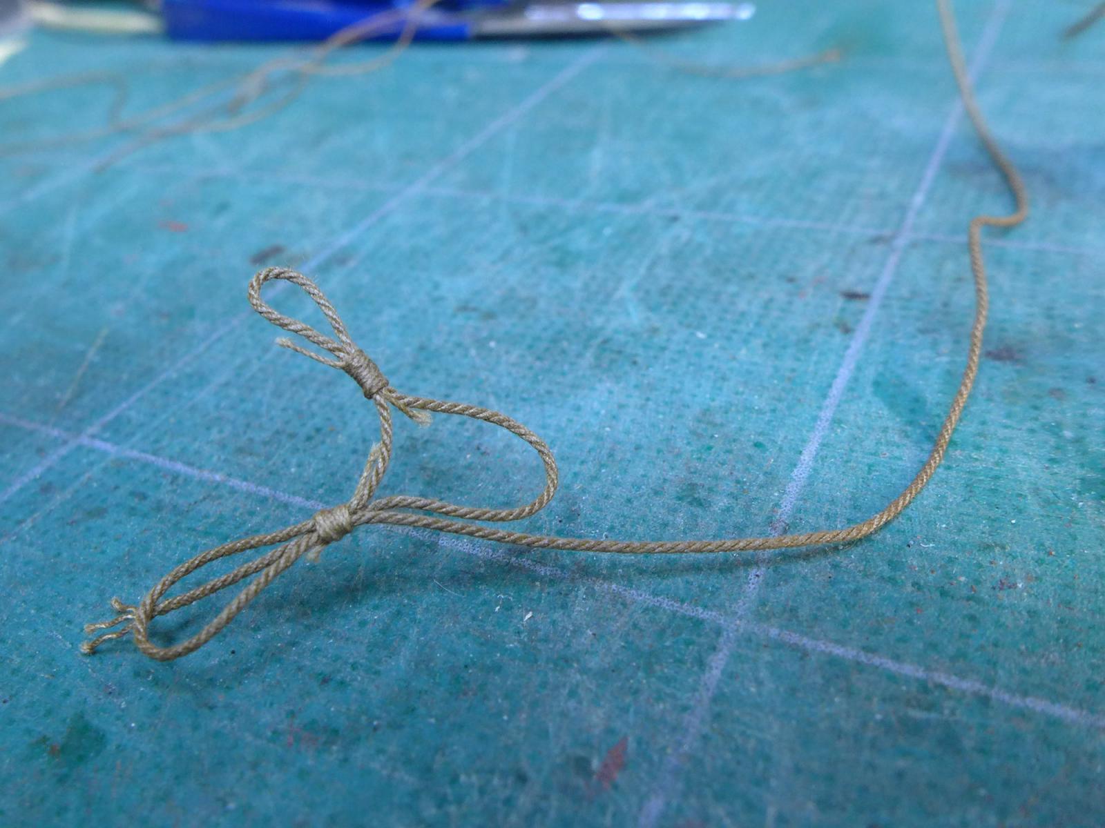
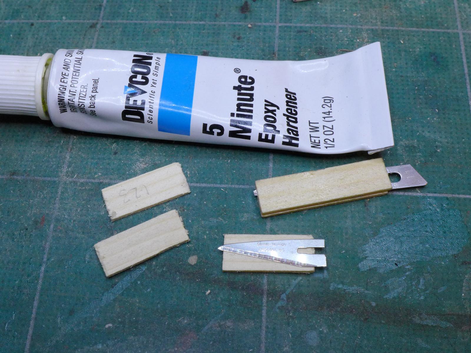
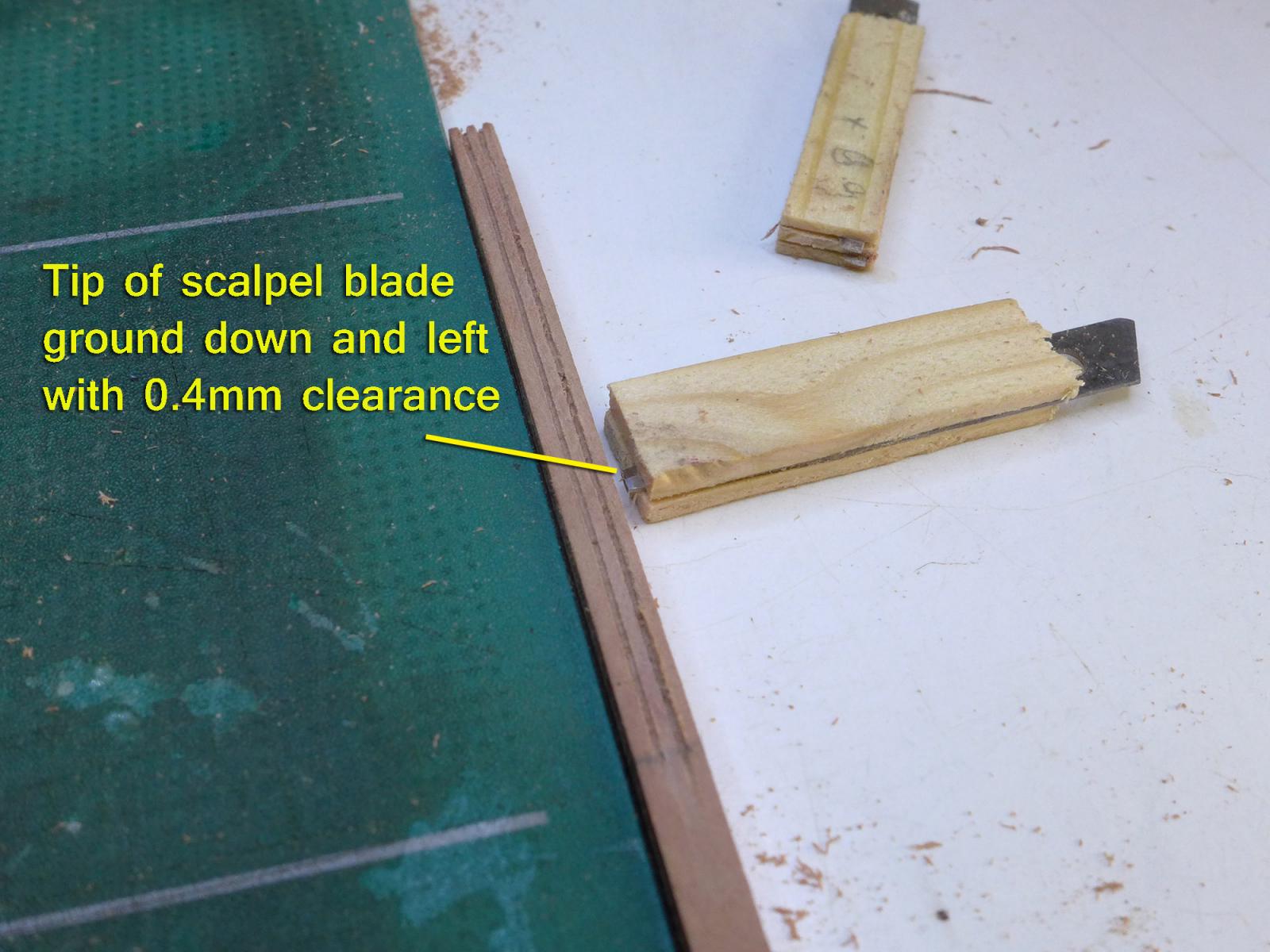
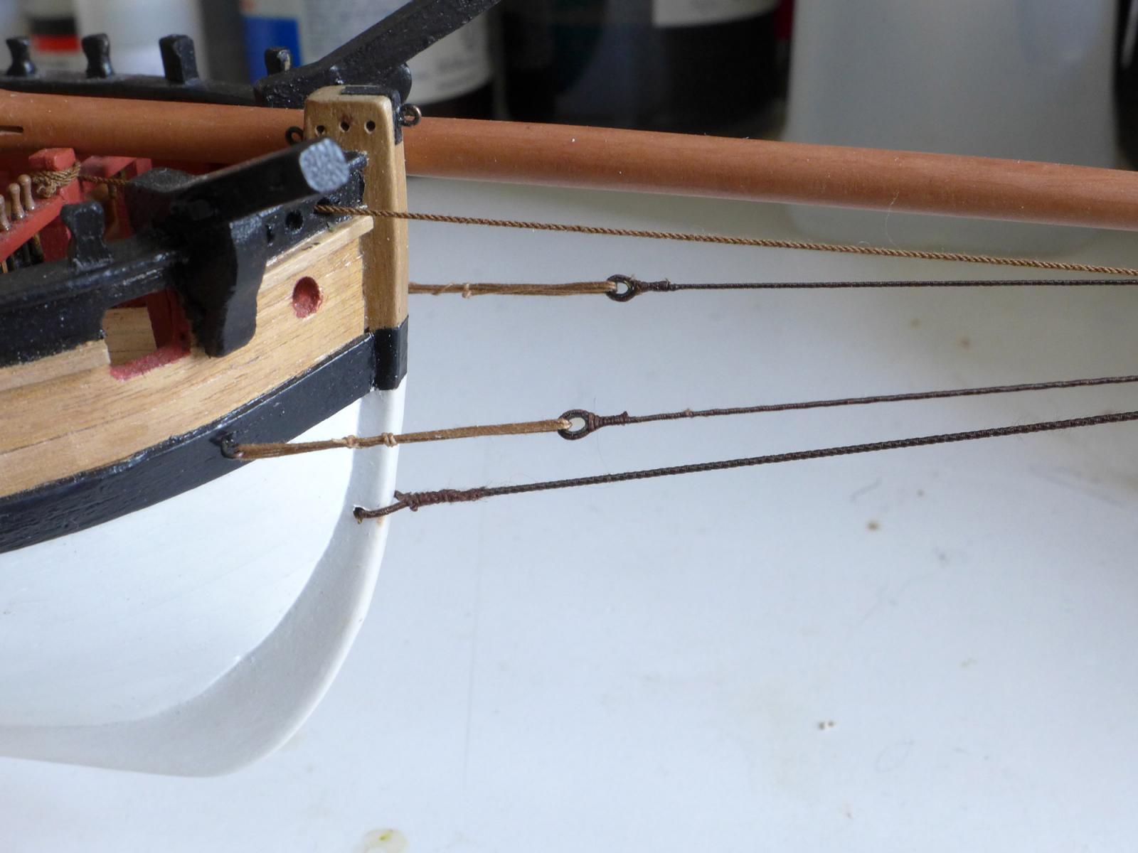
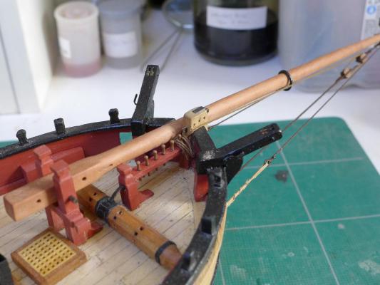
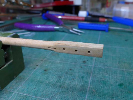
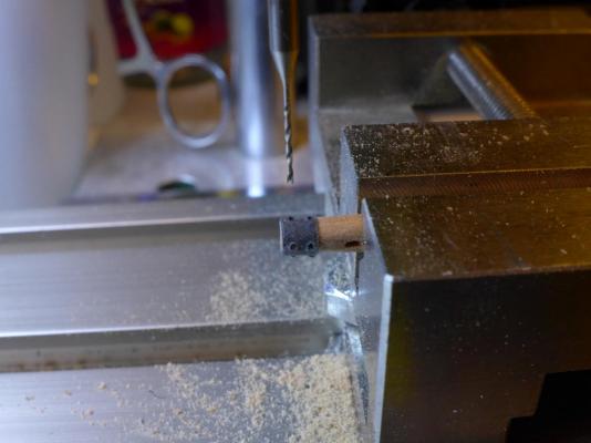
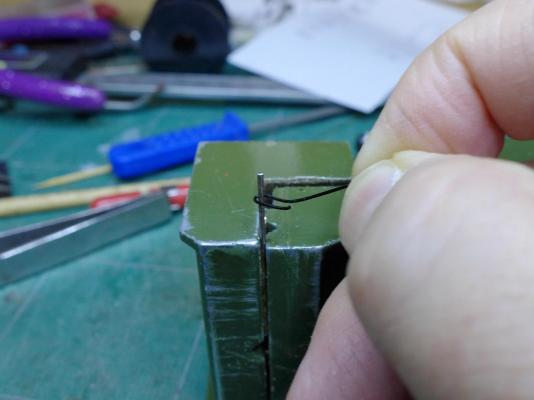
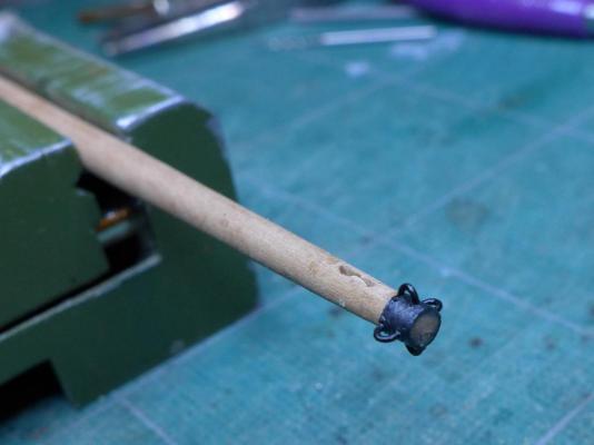
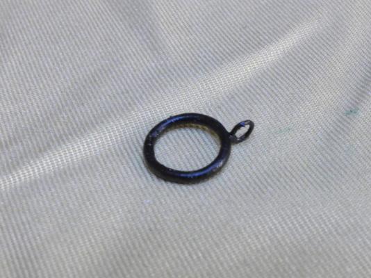
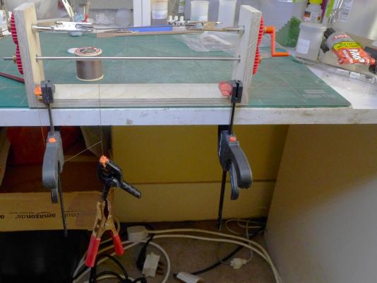
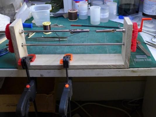
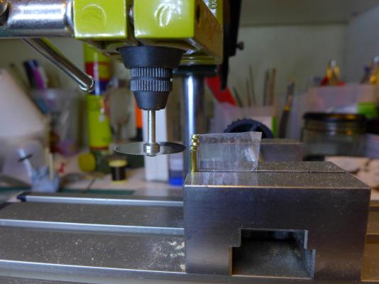
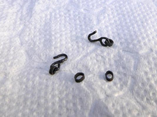
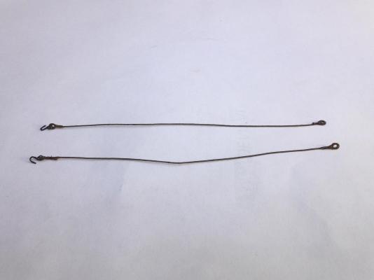
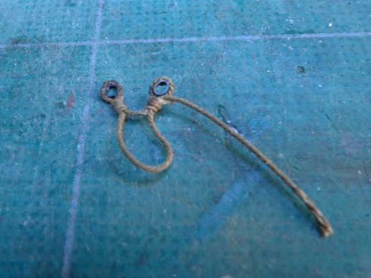
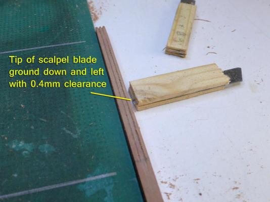
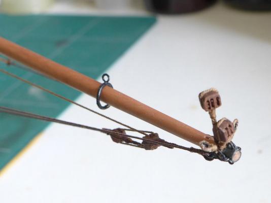
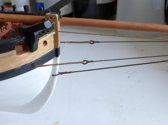
BOWSPRIT Well, as I suggested in my last log entry, I remade the bowsprit in pear as I was so disappointed with my attempts at staining the dowels from the kit. What a lovely wood is pear! This time I decided I’d look at how masts and spars were made, so I bought the low cost paperback facsimile edition from the Cambridge University Press of the first three volumes of Steel’s Elements and Practice of Rigging, Seamanship and Naval Tactics which I have discussed in another post at: http://modelshipworld.com/index.php/topic/9675-difference-between-editions-of-david-steels-books-on-rigging-etc/?p=291358 Using the measurements given by Steel, as well as by Biddlecombe in his 1848 book on the Art of Rigging, I started with square stock (instead of using dowel), used the lathe to cut it to the correct dimensions and completed it by sanding. FINISHED WITH BEESWAX AND TURPENTINE I then used a furniture cream made from beeswax and turpentine to polish it and give it a lovely golden colour. BOWSPRIT HEEL SHEAVE Reading Steel and Biddlecombe led me to a number of questions, such as how to rig the sheave at the heel of the bowsprit, which was discussed at http://modelshipworld.com/index.php/topic/9839-rigging-a-bowsprit-heel-rope-on-cutter-sherbourne-1763/?p=291354 I decided in the end just to make the sheave at the heel, and presume it would only be rigged when pulling out the bowsprit. CRANSE IRON I spent some time figuring out how to make the cranse iron at the tip of the bowsprit. Given the fact that I chose to have a bobstay, I had to make it with 4 hoops. You can see the discussion on bobstays at http://modelshipworld.com/index.php/topic/8646-bobstay-for-bowsprit-on-sherbourne/?p=256873 Initially I thought I’d try to silver solder hoops on to the iron, which I would have made from some brass tubing. However, it was clear that this would be very difficult to do since the heat from the torch would melt solder in hoops already fitted. I therefore decided to go the simple route, mimic the iron with black cartridge paper, drill holes in the iron, and glue hoops made from brass rod into the holes. You can see the sequence in the following photos: JIB TRAVELLER Then came the jib traveller, which was easily made from a brass rod and copper wire, silver soldered together, blackened, painted and covered with matt varnish: SERVING MACHINE Time to provide the blocks, hooks and tackle for the bowsprit. I made my serving machine using some steel rod from an old inkjet printer, some wood I found as scrap and plastic gears which I had to buy. The alligator clips were modified by grinding the teeth down until they were parallel when opened, epoxying wooden blocks into them, and then surfacing the blocks with carborundum paper for grip. As you can see, I used plastic clamps to provide the tension on the thread. The serving machine was also adapted for stropping blocks, but since then I have been stropping blocks just using two alligator clips embedded in a block. All the same, here are the photos: THIMBLES These I decided to make by cutting off 0.8mm thicknesses of thin-walled 1mm brass tube using my modified Proxxon which allowed me to adjust the height in increments. To stop the thimbles flying off into the universe, I first wrapped the tube in sticky tape. You’ll get the idea from the photo: The next stage was to figure out how to wrap the rope round them together with the hook. This was really easy. All I had to do was to make the hook from copper wire, silver solder it whilst the thimble was in, then attach the rope and seize it. THIMBLES FOR TOPSAIL BOWLINES Initially I was puzzled about how to make the thimbles as shown by Petersson for the topsail bowlines, so I posted a question at http://modelshipworld.com/index.php/topic/10181-how-to-make-circular-rope/?p=303151 The replies quickly pointed me to Jay Brent’s (modeller12) video at https://www.youtube.com/watch?v=WUrRb66VSSE which used the idea suggested by Bender at http://modelshipworld.com/index.php/topic/1056-tying-blocks-to-yards-or-masts/?p=17489 I therefore used this method to make the thimbles as follows: MAKING THE BLOCKS You may have noted that I’ve already tried a few ways of making blocks. I don’t think I’ll ever get it right. Nevertheless, I thought I’d try something else, using the same basic method suggested by Frolich which I have mentioned before. I found that using a straightforward pin was a bit difficult as I had to file it down to the correct width. Imagine my happiness at finding that Swann Morton no. 11 scalpel blades were only 0.4mm thick! Since the smallest hole I’m going to make for my blocks is 0.4mm, that’s perfect! All I have to do is provide wood of the appropriate thicknesses for the single, double and triple blocks. I used the tables in zu Mondfeld’s book on Historic Ship Models to determine the size of the blocks by working up from the rope sizes suggested by Steel and Biddlecombe. The following pictures show how I assembled and used the blades that are to score the sides of the blocks: Note that I ground down the very tips of the blades to provide a stronger tip. BOWSPRIT CAP ASSEMBLY I built myself a new motorised vertical ropewalk along the same lines as the Prosak developed by Alexey Domanoff and by Antonyuk (http://modelshipworld.com/index.php/topic/3593-hms-victory-cross-section-by-antony-scale-136/?p=133848), and put all these elements together. It was very satisfying: Next up: re-doing the belaying pins at the bow. Tony


- 269 replies
-
- 6
-
-
- Caldercraft
- First build
- (and 3 more)
-
18th and early 19th Century cutter models
tkay11 replied to tkay11's topic in Nautical/Naval History
Have a look at Dan Vad's blocks, Jack. He does these in the traditional way by hand after cutting lengths on a saw. Saw, scalpels, files, sanding. I am pretty determined to keep practising since it is clear some people can do it! Tony- 42 replies
-
- 4
-
-
- Cutter
- 18th Century
- (and 4 more)