mbp521
-
Posts
1,003 -
Joined
-
Last visited
Content Type
Profiles
Forums
Gallery
Events
Everything posted by mbp521
-
 Greg you are cranking out these boats faster than I can get through your build logs. Almost hard to keep up. Beautiful work on fleet! The grunginess and weathering is all too realistic looking. Just amazing! -Brian
- 200 replies
-
- 5
-

-
- Transport No. 103
- Hasegawa
- (and 4 more)
-
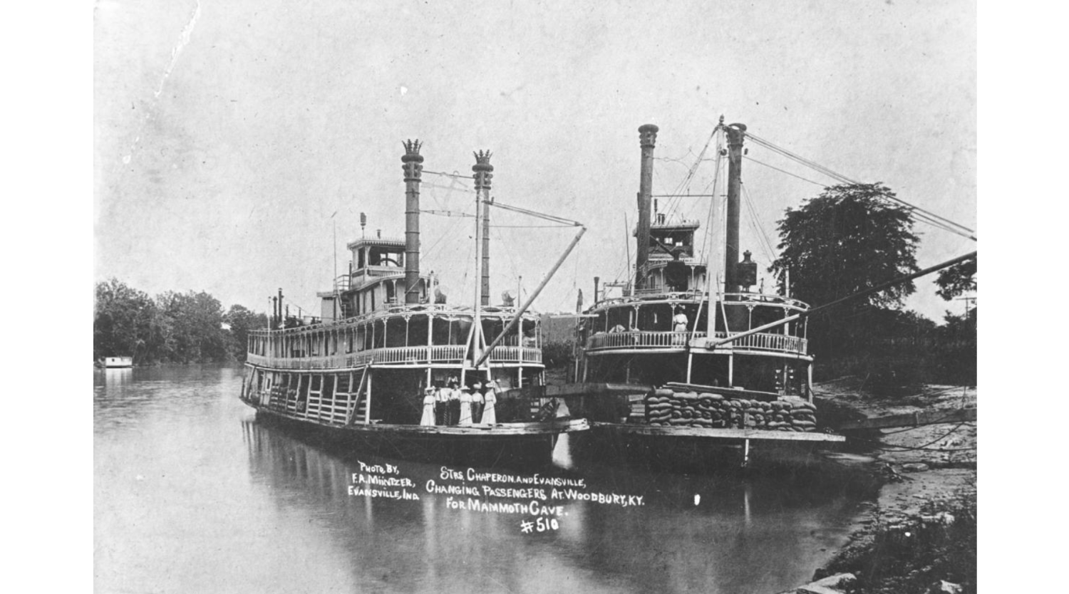
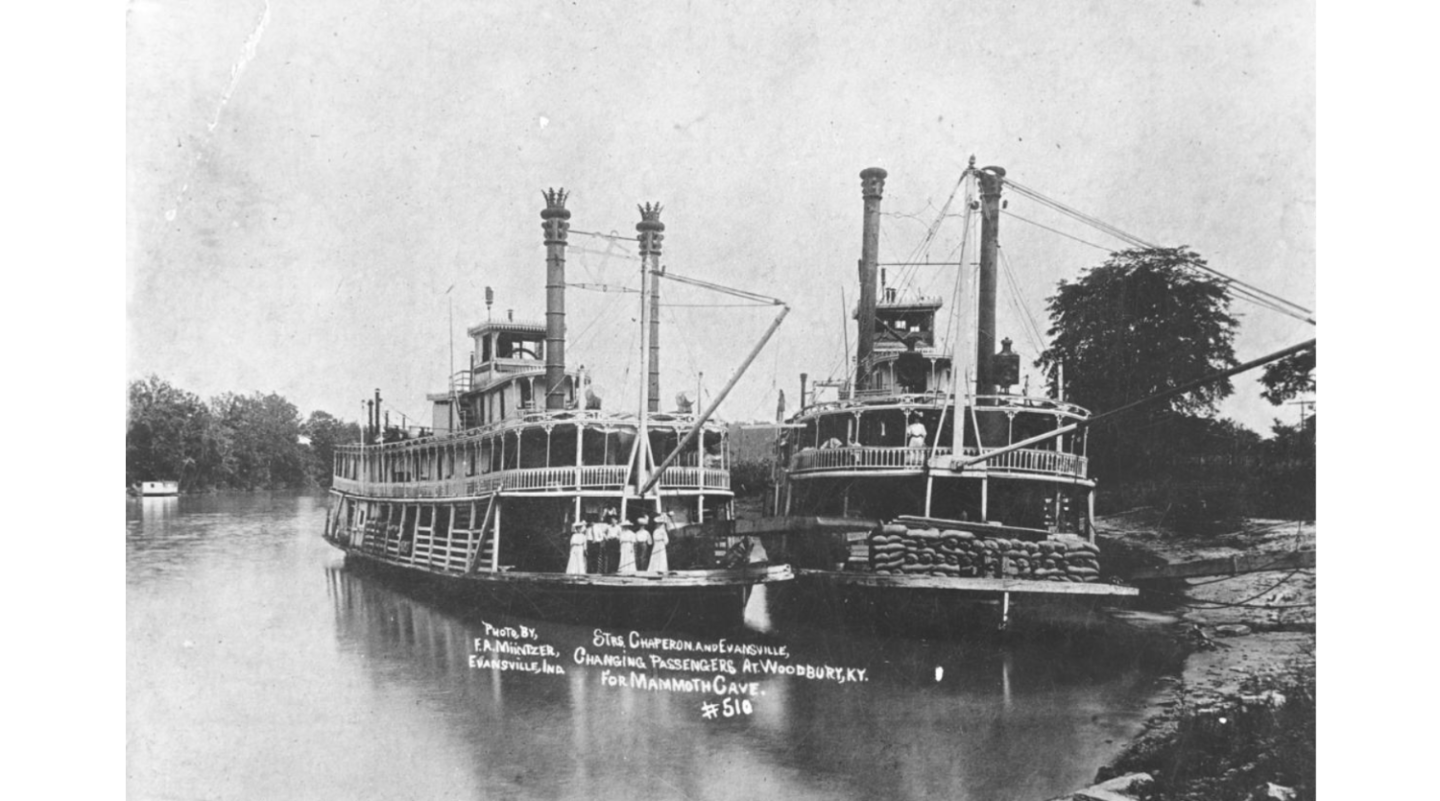
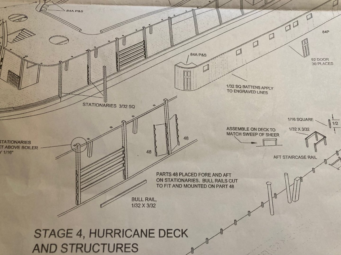
Speaking of following instructions, this conversation reminded me of another area of where the instructions are wrong and I didn't realize it until it was too late. When you get to Stage 4, the instructions show to mount the bull rail braces, part 48, to the stationaries with the opening outboard and placing the bull rails from the outboard side.. To be historically accurate, they were actually mounted the other way around to where the bull rails could be installed from the inboard side. I found this out later on when I was studying some of the contemporary photos of the boat. In the below photo, the Chaperon is on the left. If you zoom in to the starboard side where the bull rails are mounted you can just make out the framework of the braces that show them mounted this way (I thought I had a better picture of this, but I can't seem to find it right now). It would also make sense that they be installed from the inboard side, due to the fact that if a person or livestock were to lean against, or run into them they could knock the rails out of place and fall overboard. -Brian
- 158 replies
-
- 2
-
-
- chaperon
- Model Shipways
- (and 1 more)
-
Beautiful work Tom, and congratulations! So sad to see the build come to an end but can't wait to see what's next. Thank you for putting this log together, I have it bookmarked for when I finally get around to building my kit. -Brian
-
It's that fine line that we dance on with the Admiral between work and play. A couple of years ago I bought the Admiral a Cricut for Christmas. She had said she wanted one and I thought, why not, it would keep her busy enough that she would leave me alone with my shipbuilding. Well so far, I think I have used the Cricut just as much as she has. And the honey-do list continues to grow. -Brian
-
John, you absolutely got it right. I ran into the same issue with my build and placed them on the 2nd & 3rd posts for that same reason. Also good thinking on reinforcing the boiler deck, a decision you will not regret. I went as far as using scrap pieces inside of the walls as well to keep them even at the tops and bottoms since the walls were so long and flexible. It added a lot of stability to the structure. She is really coming along nicely. -Brian
-
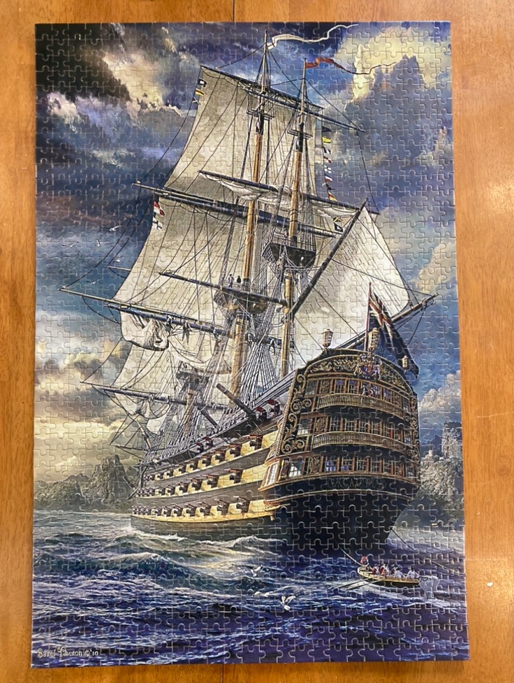
Thank you all for the well wishes. Even though I am not able to work on an actual wooden model ship build, I am able to work on wooden puzzle of a ship. 😁 While entertaining, still nothing like making some sawdust. Hopefully only a couple of more weeks in this contraption and I can get back to it. -Brian
-
So glad to see you back at the bench again Keith! I can’t wait to delve into the upcoming updates. Kind of the opposite with the sunny days, I tend to find myself wanting to work on a build more on the cloudy days and wanting to be outside on the sunny ones. Of course wintertime sunny days can be a bit deceiving sometimes here in Texas, I can only imagine a sunny day in Michigan in the winter. I’m sure that would change my thinking in a hurry. -Brian
-
I have a whole box of unused drawer pulls sitting in my barn collecting dust. Now I have a prospective use for them. What a unique idea Keith! -Brian
-
Man that structure is tiny! I don’t think there is any way that I could do a full build at that scale. Even the tiny bits on my boat gave me fits. Definitely like the added details. -Brian
- 113 replies
-
- 5
-
-
- Cairo
- BlueJacket Shipcrafters
- (and 1 more)
-
Looking good Tom. I’ve never been a fan of the Britannia parts MS uses in their kits, and I often replace them with scratch built pieces when I can. Needless to say though, you did a great job on straightening and cleaning up the kit pieces and the bird cage looks wonderful. It will be a bittersweet day when “Finished” is added to the title of this build log. -Brian
-
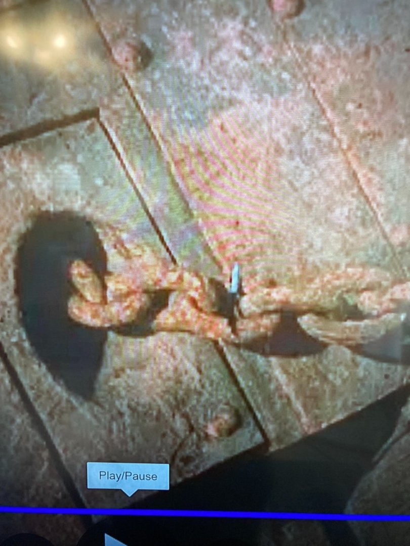
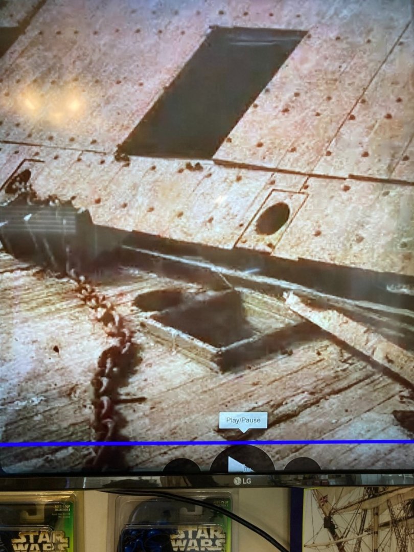
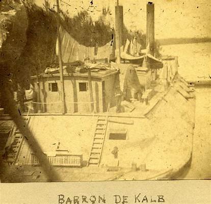
Playing catchup on the build log entries. There seems to be a lot of information posted lately, Roger, to answer your question about whether the Cairo use rope or chain to attach the anchors, I would say that it was chain. The below pictures were screenshots that I took from a conference Edwin Bearss gave just before he passed away. In his presentation he had these photographs taken during the recovery efforts up on the screen. I searched in vain to find the actual photos and finally settled on just taking a picture of my computer monitor (hence their graininess). One picture shows the starboard chain going through the hawse pipe and the other shows the chain draped across the foredeck. The port hawse pipe empty so it would somewhat be hard to tell if there was a chain or rope attached to the portside anchor. There is documentation from journal entries of sailors aboard the Cairo and the other boats in the flotilla, at the time she struck the torpedo that tell when the explosion occurred the port anchor was launched from the deck. If I remember correctly, one of the flukes from this anchor is on display in the Cairo museum. So the possibility of the port chain being broken and with the force of the explosion could have cause it to recede through the hawse pipe and would not have been visible during salvage. Or this hawse pipe could have simply been strictly used for rope to tie the boats off to the shore. During my build, I struggled with the same question, how did they haul in the anchor with a capstan that was designed for rope. I came up with one possibility that they would use a length of rope attached to a hook or a loop. They would secure the hook through the chain loop and run the rope through the hawse pipe and around the capstan and haul the chain up a little at a time. This by no means would have been an efficient method of doing it, but as with John Howard and the rest of the St. Louis team have stated, documentation is scarce. So with the limited information on this subject, this is the way I incorporated it into my build. As also stated previously, most of the time these boats were tied up to the shores of the rivers, but there were times that they were at anchor. Given that many of the Western Rivers were not known for their great depths at the time, there was the possibility that there would not have been much anchor chain to haul in. Just my two cents. -Brian
-
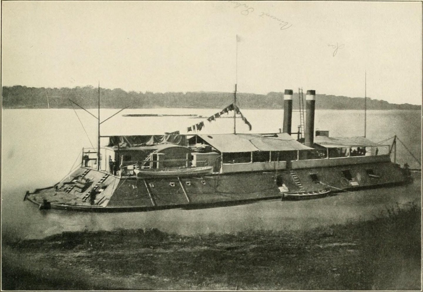
This was a real noggin scratcher when researching how to build the roof on the forward and aft structures of the paddlewheel house, and to be honest I can't remember if I covered it or not. Since there is only one known existing photograph of the Cairo it is really hard to tell how this was constructed. I stared at the picture for hours on end trying to figure it out. The HSR plans show the roof to be flat and I think they were drawn that way going off the Cairo photograph. But the more I researched and studied the picture I came to the conclusion that what it looks like in the Cairo picture that makes the roof look flat is the loading booms that were sometimes attached to the aft mast pole were stored on top of the forward roof when not in use. These booms can be seen in the Cincinnati photo in my previous post, and I added them as a deck detail on my build. Since the Cairo, Mound City and Cincinnati were all built at the Mound City shipyard, I took it upon myself that they would have all been built the same way. The contemporary photos of the Cincinnati and Mound City, show that the rooftops on these two structures do have a curve to them as well as the four other boats built in the Carondelet shipyard, so why would the Cairo be the only one with flat rooftops. This was my reasoning for building my version with the curved roofs. I may have gotten it wrong, but I think it will definitely be hard to disprove my theory that the Cairo had round rooftops as well. 😁 In the back of my mind I would sure like to know for sure, but there is just not enough information out there on it. I'm sure the guys in St. Louis have run into the same issue, but since there is a photograph of they aft end of the St. Louis, they had an easier time with this part. -Brian
- 113 replies
-
- 4
-
-
- Cairo
- BlueJacket Shipcrafters
- (and 1 more)
-
Eric, your solution to your pilot house conundrum worked out great. This was indeed an unusual shape to get correct and I struggle with it a lot. I ended up making several mock-ups with card stock for the sides trying to get the angles correct, and the forward three panels with their added thickness just made it that much more difficult. At least the kit provided a resin mold to somewhat ease the pain of getting the shape correct. For your comment above, I know I am a little late in responding, my apologies but my arm was giving me fits this past weekend and my pain medicine tends to make me a little loopy. However, the curved section over the paddlewheel was not "roofed" like the rest of the structures built around it. From the contemporary photos of the City-Class boats I was able to discern that this area was planked with much thicker timbers (much like the deck material) and the rest of the structures were thinner planks and tarpapered. This can be seen in the photos of the Cincinnati and St. Louis. The pitch of these roofs was minimal. Basically just enough to shed the rainwater off. I believe is set my pitch at about 3-4 degrees. Hope this helps. -Brian
- 113 replies
-
- 4
-
-
- Cairo
- BlueJacket Shipcrafters
- (and 1 more)
-
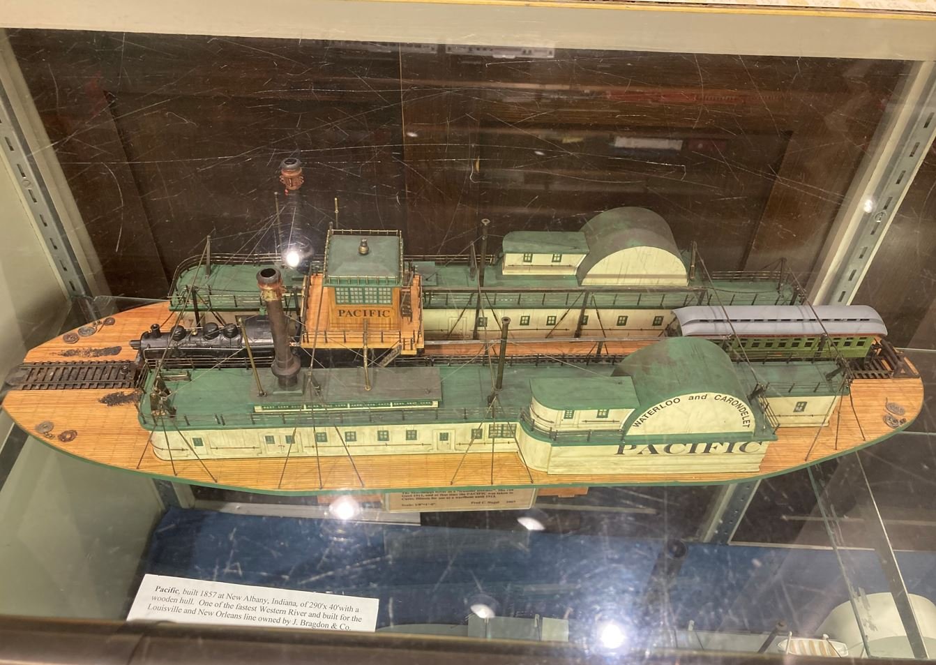
Another suggestion I could offer up would be, if the wood "armor" is even all the way around and matches up at the corners of the resin form, you could possibly glue them all in place on the resin cast and line them up at the top. Once everything dries, you could then do as Ken @Canute suggested and sand the bottom down on a piece of glass or other hard flat surface until the bottoms all match up. As a side note, to entice you on a previous post about a railroad ferry project, I took this picture in the Vicksburg Rail Road museum on our visit last year. I thought it looked like a pretty neat project, and something that I had thought about doing some day. My great-grandfather worked for Union Pacific years ago and was in charge of shuttling the RR cars on a ferry similar to this one between Baton Rouge and Port Allen. -Brian
- 113 replies
-
- 9
-
-
- Cairo
- BlueJacket Shipcrafters
- (and 1 more)
-
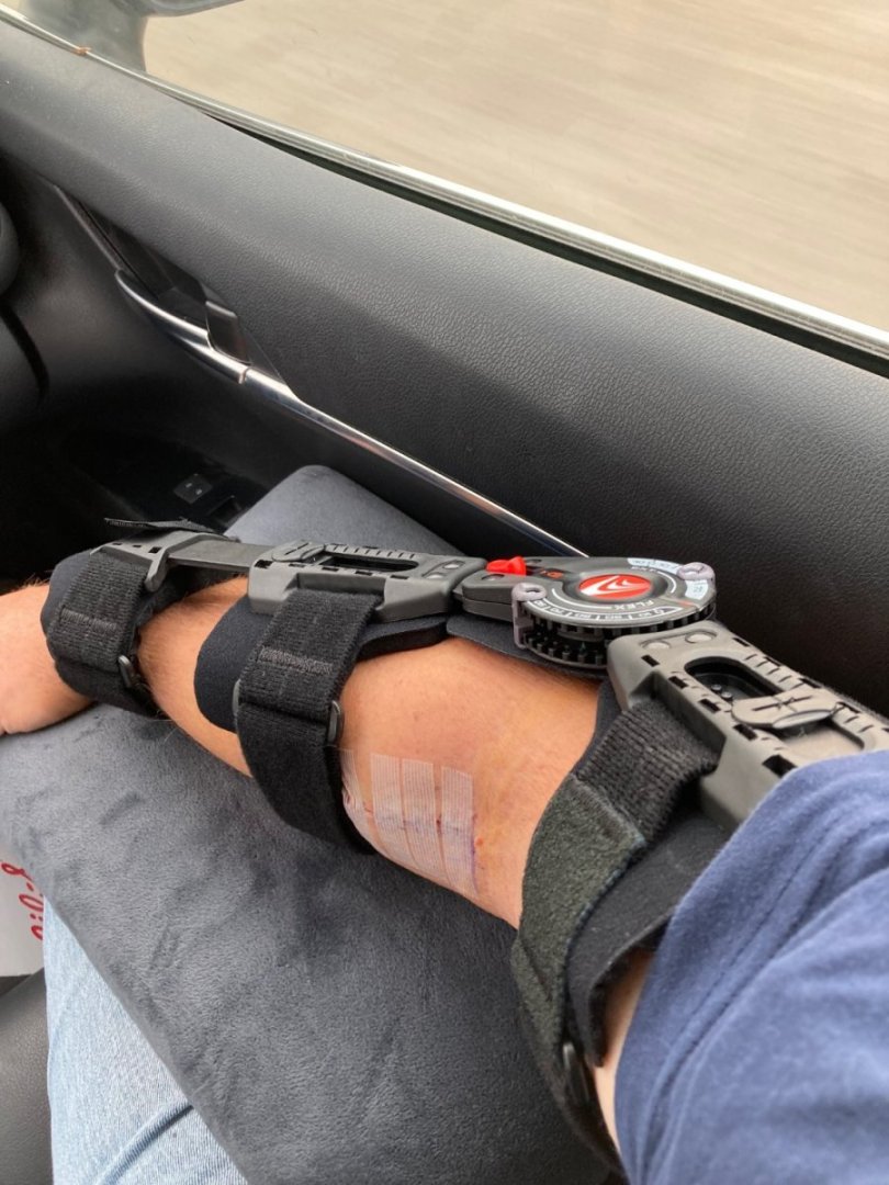
"Resistance is futile" 😁 It is a contraption alright, and real fun to try and sleep with at night. I've been dealing with the issue since early November, and since we had already met our medical deductible for the year I figured I'd go ahead and get it done. It was also under Admiral's orders. -Brian
-
That would be an almost unimaginable sin to drill holes in such a fine hull. Glad you took the alternate route and went with the cradle idea. -Brian
-
Finally back to where I can function again. Had to have little work done to repair a torn bicep tendon. Just got the cast off today, and now I have to wear this contraption for 5 weeks. Man this is sure cutting into my build time. I am anxious to get started on my next project, but I don't think I am quite ready. With the time it took me to type this up it may be a while. In the meantime I have a bunch of catching up to do on other build logs since I can now operate the computer again. Hope everyone had a great holiday season and is ready for 2023. -Brian
-
Merry Christmas Eric! Sorry for all the heartache you are having with this build. I’m just following along and I get frustrated at the inaccuracies. But, I am so glad that you are pointing them out and finding great solutions to fix them so others that build this kit will be able to make the needed adjustments. You guys, and the rest of you MSW members up north please stay warm through this arctic blast. It’s been in the negative numbers here for wind chills the past couple of days and I am really not ready for it. -Brian
- 113 replies
-
- 5
-
-
- Cairo
- BlueJacket Shipcrafters
- (and 1 more)
-
Just taking a second to wish all my friends here on Model Ship World a very Merry Christmas and a safe and Happy New Year!! -Brian
-
Amazing job Keith! I’m wondering how you find the time to work on the Germania, keep up with your detailed log, and keep your workshop so tidy. If I try real hard I can usually accomplish two of those three tasks at once, but somehow you can do all three. Truly a fascinating build, sad to see it approaching the finish line. -Brian
-
Yves you are correct. Every now and then I run across something that is reasonably priced. The lanterns I used were not terrible, about $1 a piece, but I have seen some things that were just outrageous. Most of it depends on the designer. -Brian
-
Congrats on getting her done. Looks like a lot of builds are wrapping up before the new year. Beautiful work, can’t wait to see what’s next. I may have to add this one to my wish list. -Brian
- 238 replies
-
- 2
-

-
-
- Robert E Lee
- steamboat
- (and 3 more)