HOLIDAY DONATION DRIVE - SUPPORT MSW - DO YOUR PART TO KEEP THIS GREAT FORUM GOING! (Only 20 donations so far - C'mon guys!)
×


Gerhardvienna
-
Posts
683 -
Joined
-
Last visited
Content Type
Profiles
Forums
Gallery
Events
Everything posted by Gerhardvienna
-
Cutty Sark by NenadM
Gerhardvienna replied to NenadM's topic in - Build logs for subjects built 1851 - 1900
Hi Nenad Just a bit rough, but a good first attempt. I know from your former builds, you can do that much better. Try to turn the spokes, if you dont have a lathe, you can use a drilling machine, fixed to your workbench. This brass spokes will not fit to what you can build, use toothpicks as you have shown earlier, and grind the careful to recommended size. Good Luck, have sucesss! Regards Gerhard- 4,152 replies
-
- 6
-

-
- cutty sark
- tehnodidakta
- (and 1 more)
-
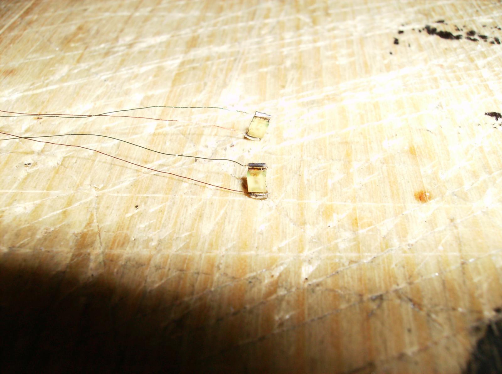
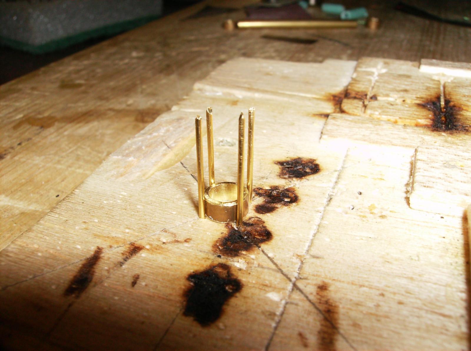
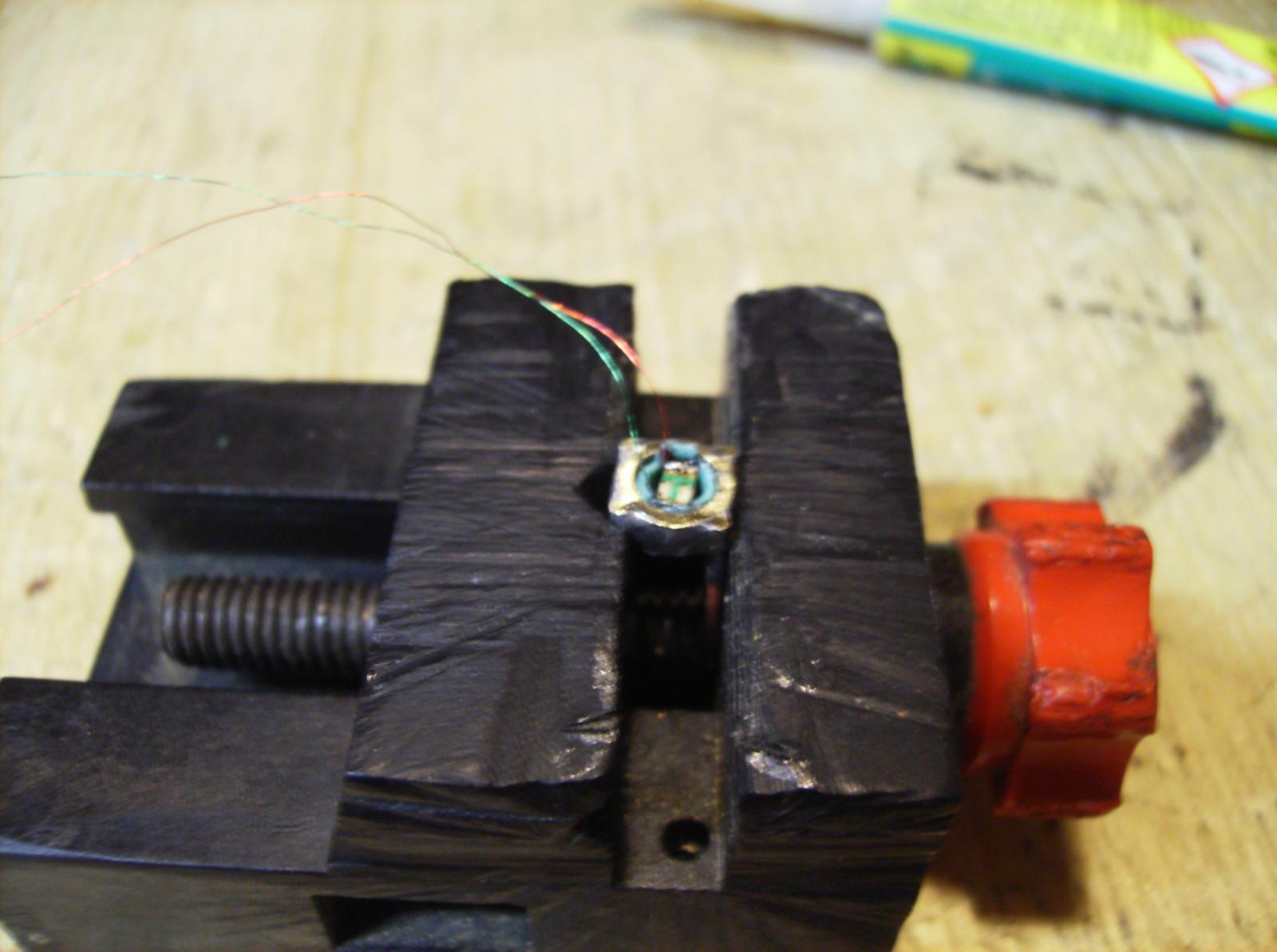
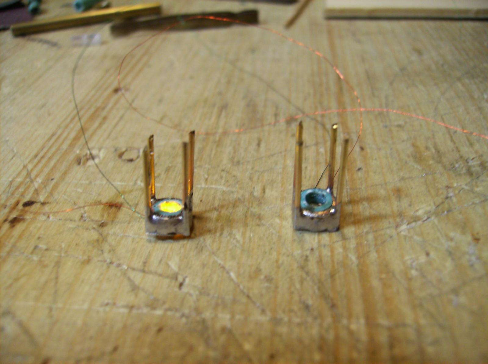
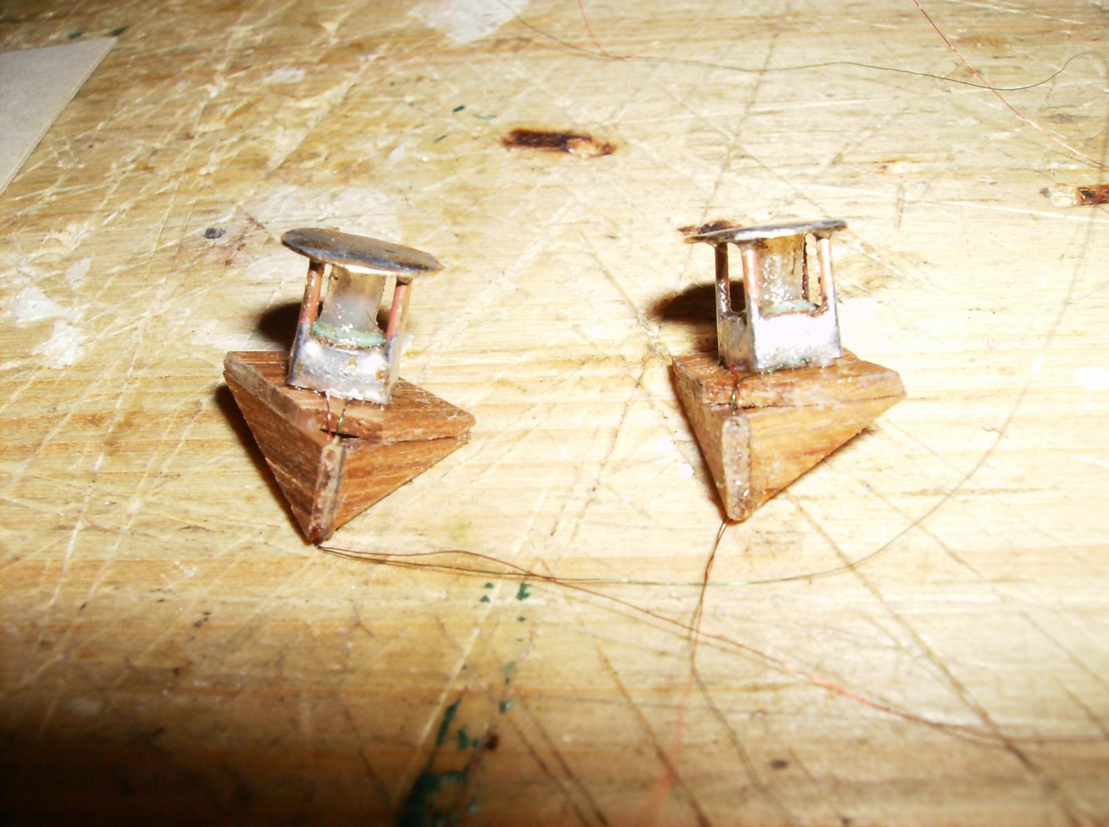
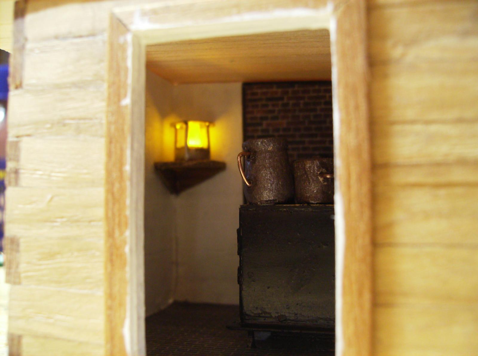
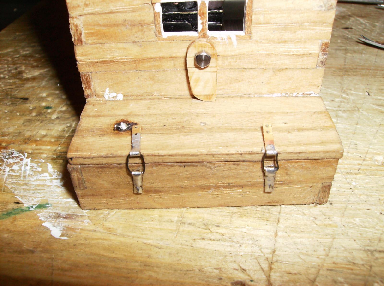
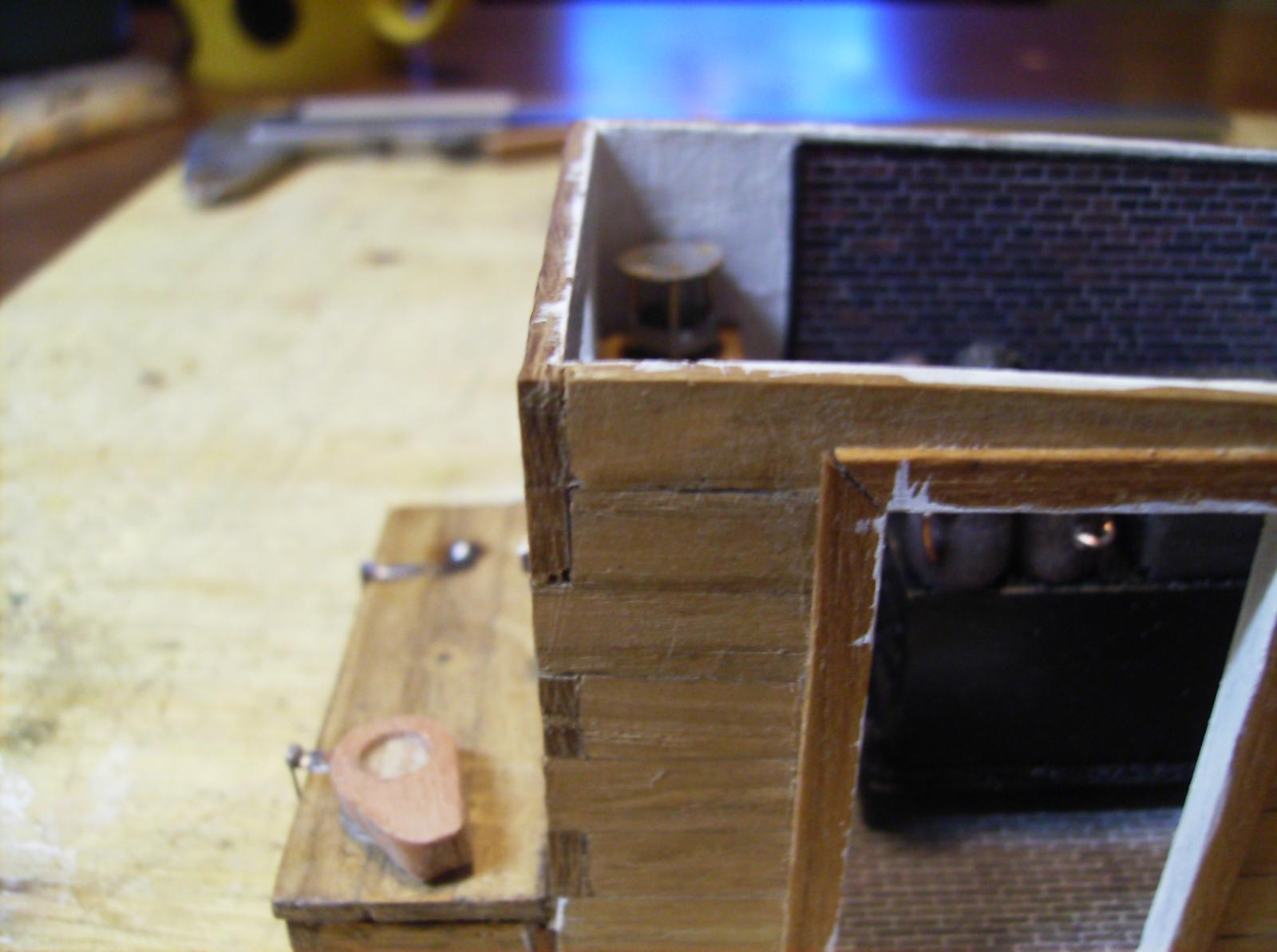
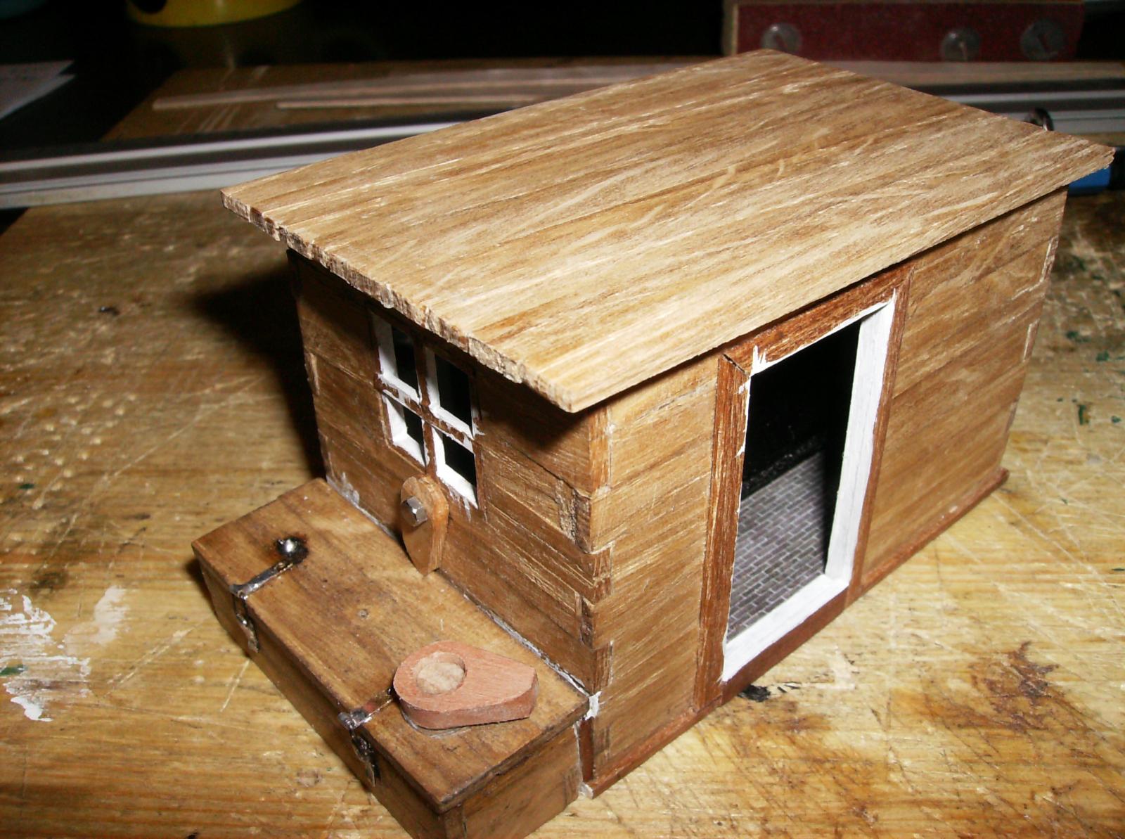
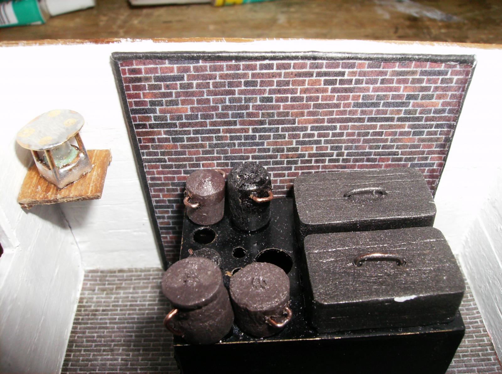
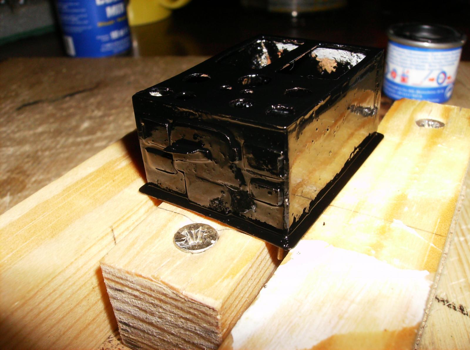
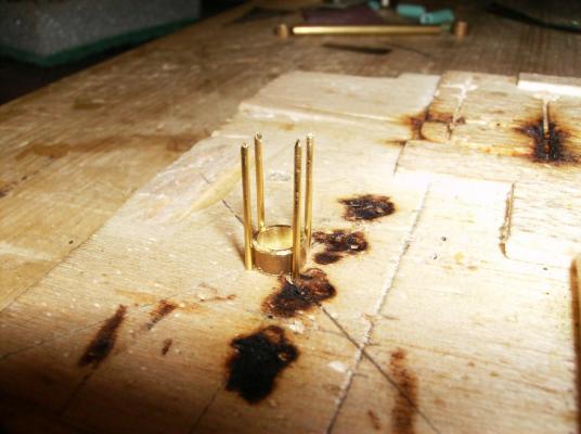
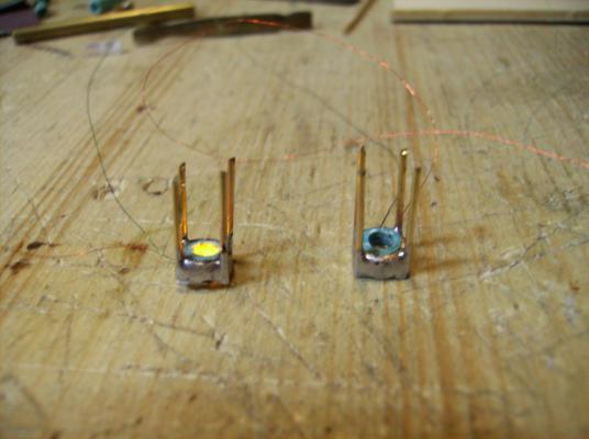
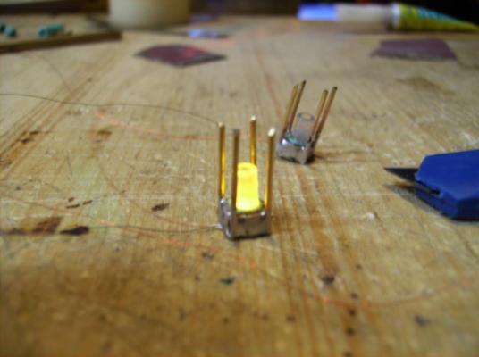
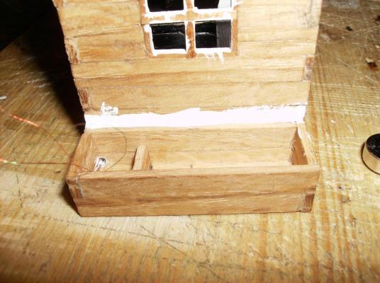
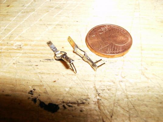
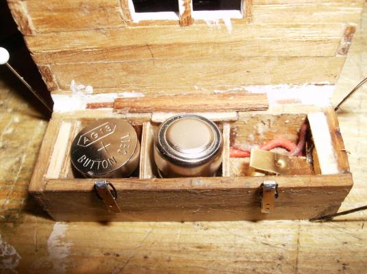
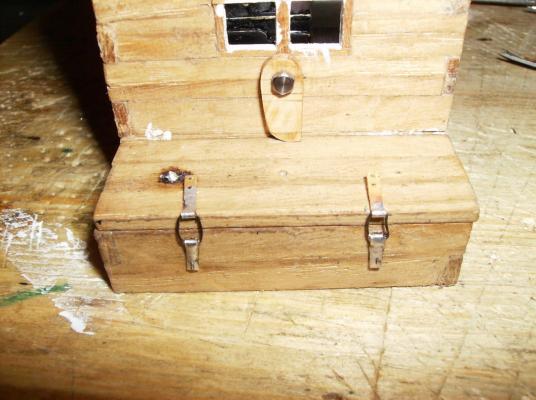
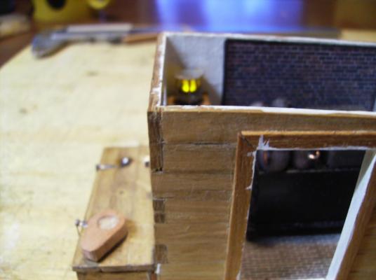
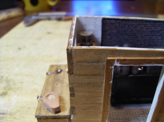
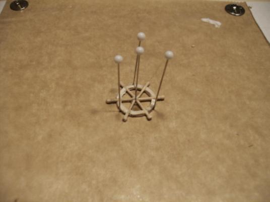
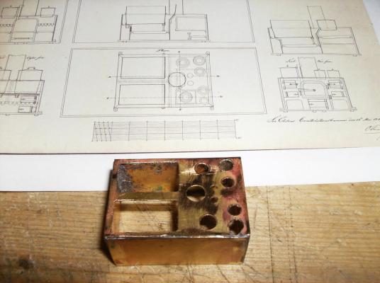
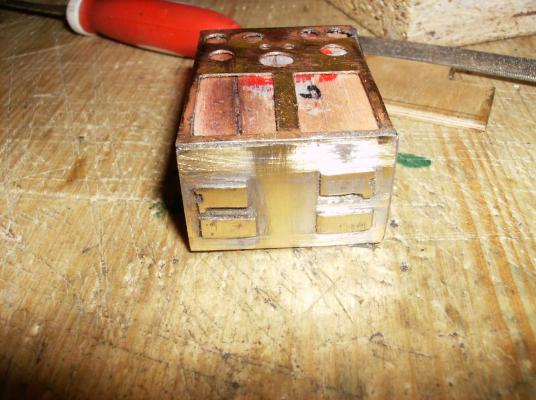
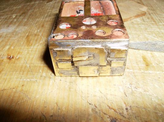
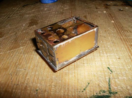
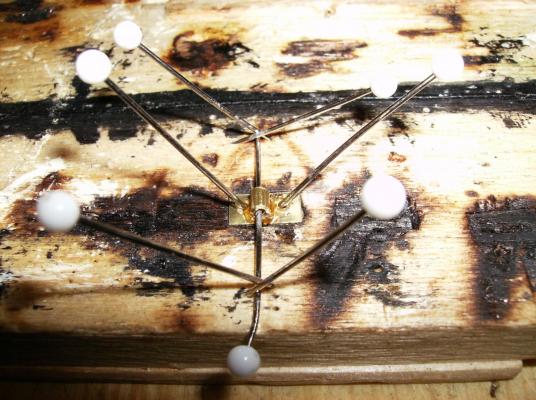
Hi again! First as ever, many thanks for your kind Likes ! As you can see in the former post, there`s light in the cookhouse. First I soldered emailled wire to 2 SMD-Led`s, the Led`s are only around 2 x 1 mm small. As a next step I used 4 pieces of 0,5 mm brass rod, cut them to length with circa 5mm overlength, stuck them into a piece of balsa wood, and placed a short piece of 4 x 3 mm brass tube in the middle. All was soldered together, and then the overlength filed away. On the bottom side I stuck a piece of 3 x 2 mm plastic tube into the brass, this works as an isolation for the wires. A first test, there`s a light (over at the frankenstein place..............) The glass cylinders are simple tubes of acrylic glass tubes. They came from medical inhalers, wich I need for the cure of COPD. In the end I soldered end caps of 0,1 mm brass sheet to the lamps, grinded all to shape, and glued the lamps to corner stands. As glue I used glueing silicone, this takes a bit more time for drying, but fixes the lamps best to their stands. One of the lamps mounted into the house The lamps need some power, as we know, so I decided to build a battery box beneath the cookhouse. This box took me more than only one attempt, until I had it finished. This was the first version Some working hinges were to make, the box can be opened for change of batterys The final version of the box. This wall-mounted lever keeps the box closed This lever on the box works as a switch, left position turns lights on. The cookhouse with its roof. The roof was made from the same materials as the walls. Regards, hope you enjoy that......... Gerhard


- 108 replies
-
- 12
-
-
Hi Paul No wonder, that he`s doing it so accurate........... I have read the thread about Hahn herein, he was a real master of his own class. Regards Gerhard
-
Hi Paul Sorry for that late response, The cans were simply turned freehanded at the lathe, the pots have been remains from 12 mm balsa wood. With a bit of color and a few copper wire they are now converted into their final destiny There is NO waste in the shop, even the smallest piece of wood or metal can be used for just something. Regards Gerhard
-
Hi Paul, Do you have a link to that tutorial? Would be interesting, thank you! Regards Gerhard
-
Hi Paul Big show! Your pump looks as it could work immediatley! I LIKE IT. Regards Gerhard
-
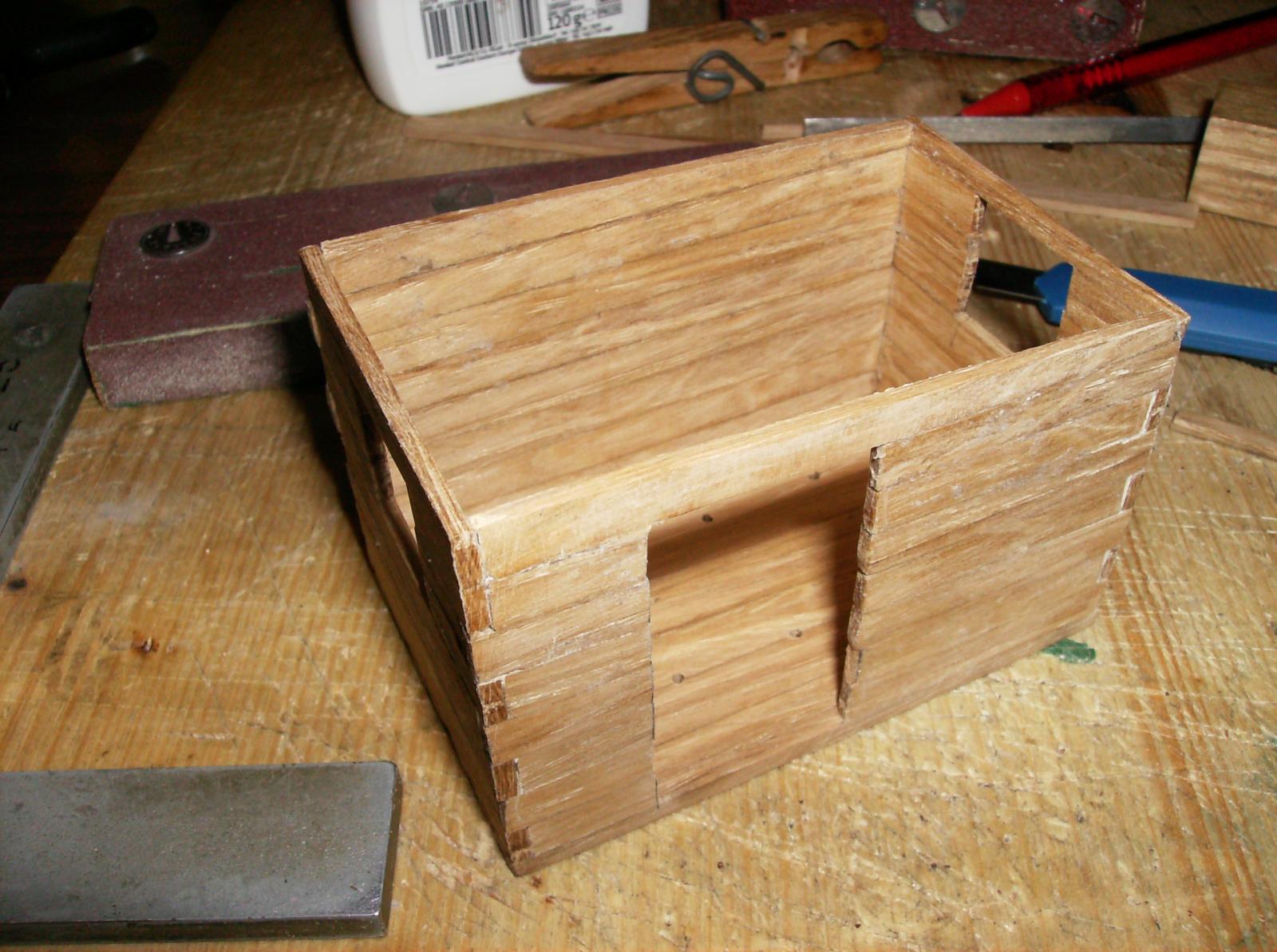
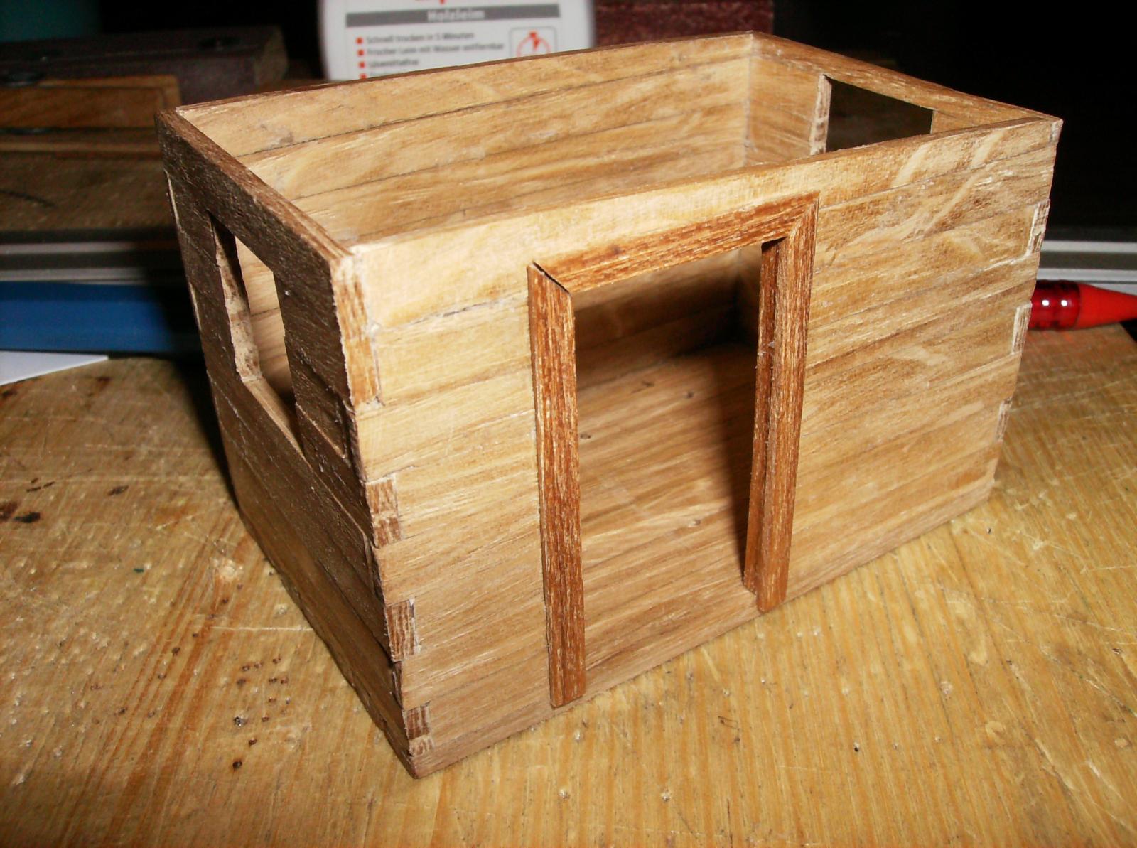
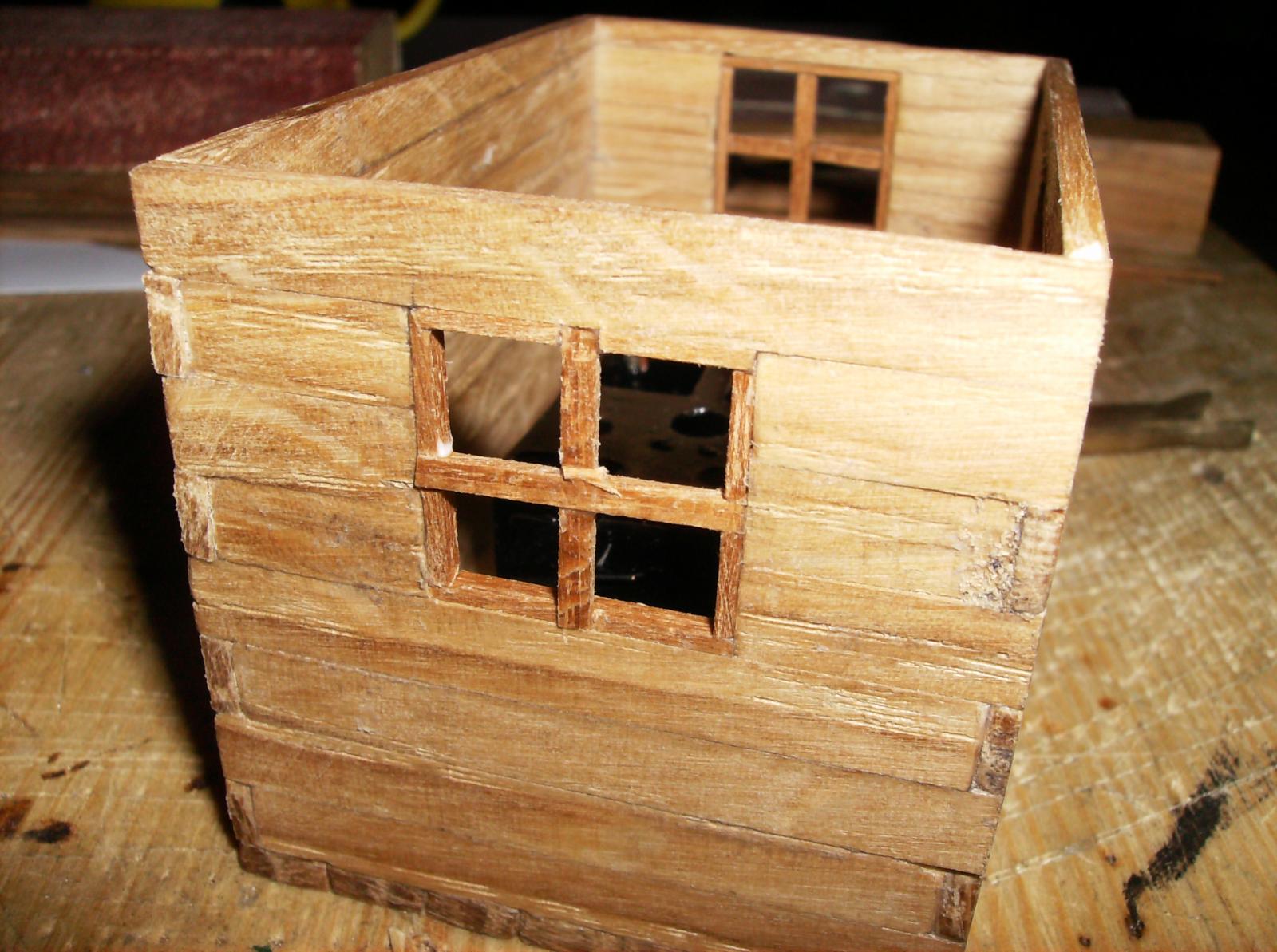
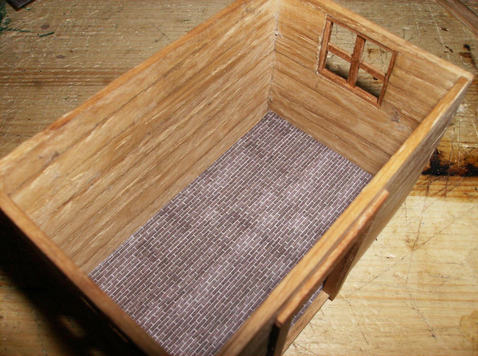
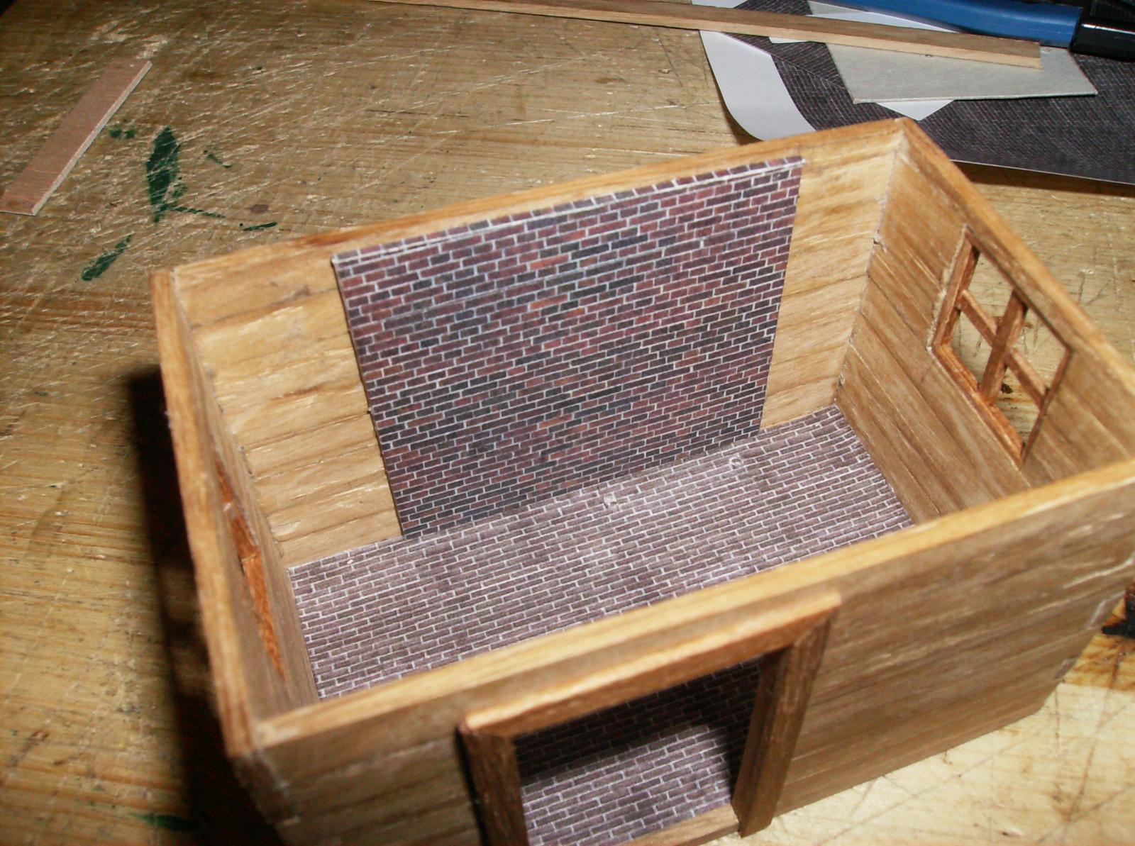
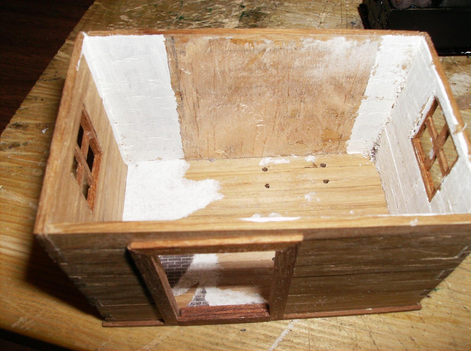
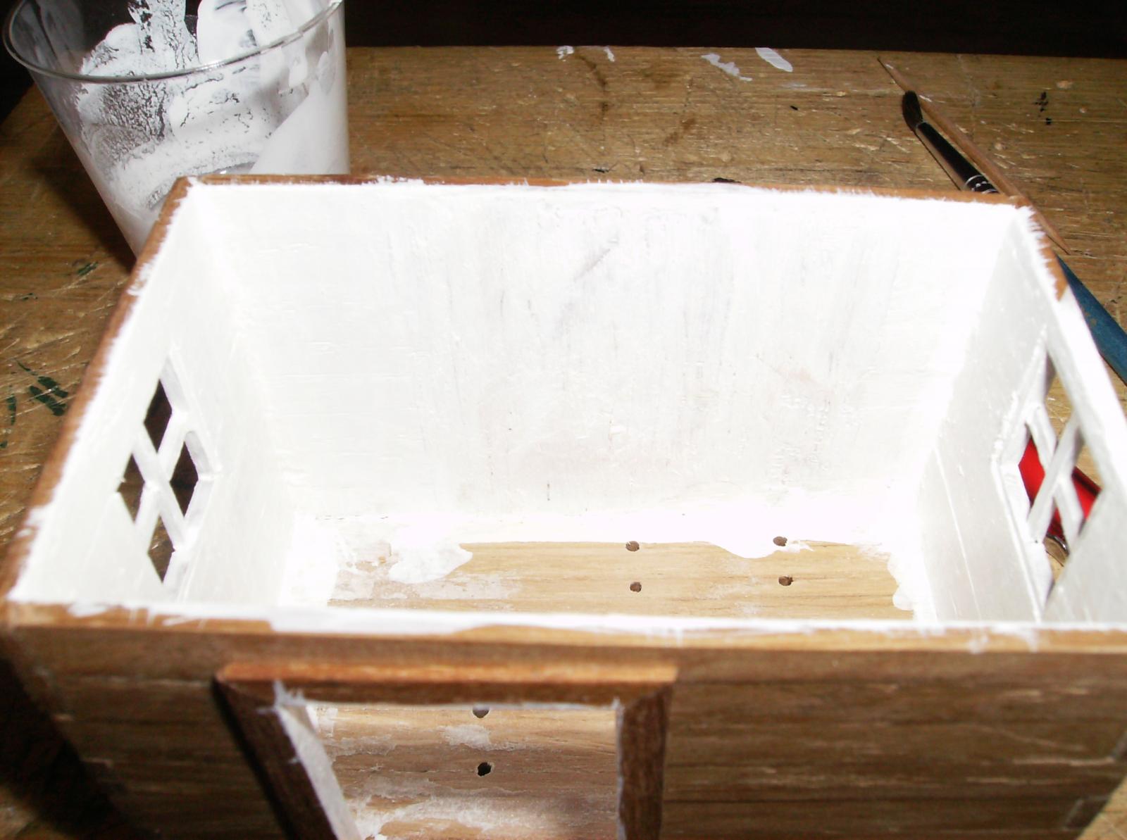
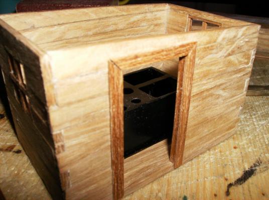
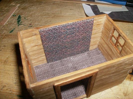
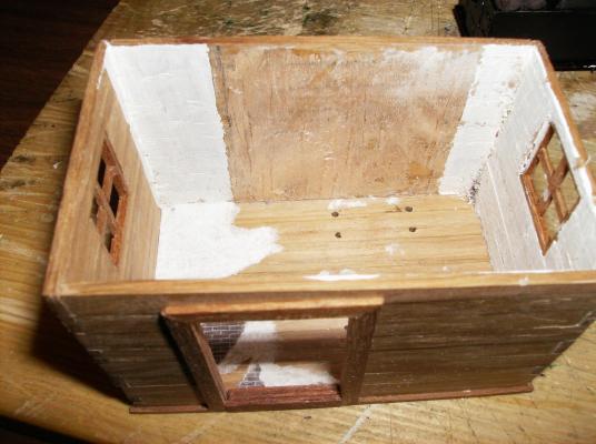
So we can go on, next photos are sorted out. After building the stove i started with the cookhouse. I used 6 x 2 mm oakwood stripes, and glued them as walls together, the floor was made from the same material. The door- and windows frames were made for darker wood, that I had in stock from a former project. Then the stove took place for a short test, space enough for the cook to walk around! After that test I layed the clinker floor and wall into the house, what was a mistake at that time. The clinker photos I used was downloaded from Google search for "clinker floor", and resized to the correct measure. As W. E.Falck told me in another forum, the walls were chalked white, so I had to remove everything, an painted the walls with white matt colour. Even two lights were made, this will be shown in a next post......... Best regards Gerhard


- 108 replies
-
- 10
-
-
Hi Johann Big art as ever, maybe I come to this level somewhen ................. Regards Gerhard
-
Cutty Sark by NenadM
Gerhardvienna replied to NenadM's topic in - Build logs for subjects built 1851 - 1900
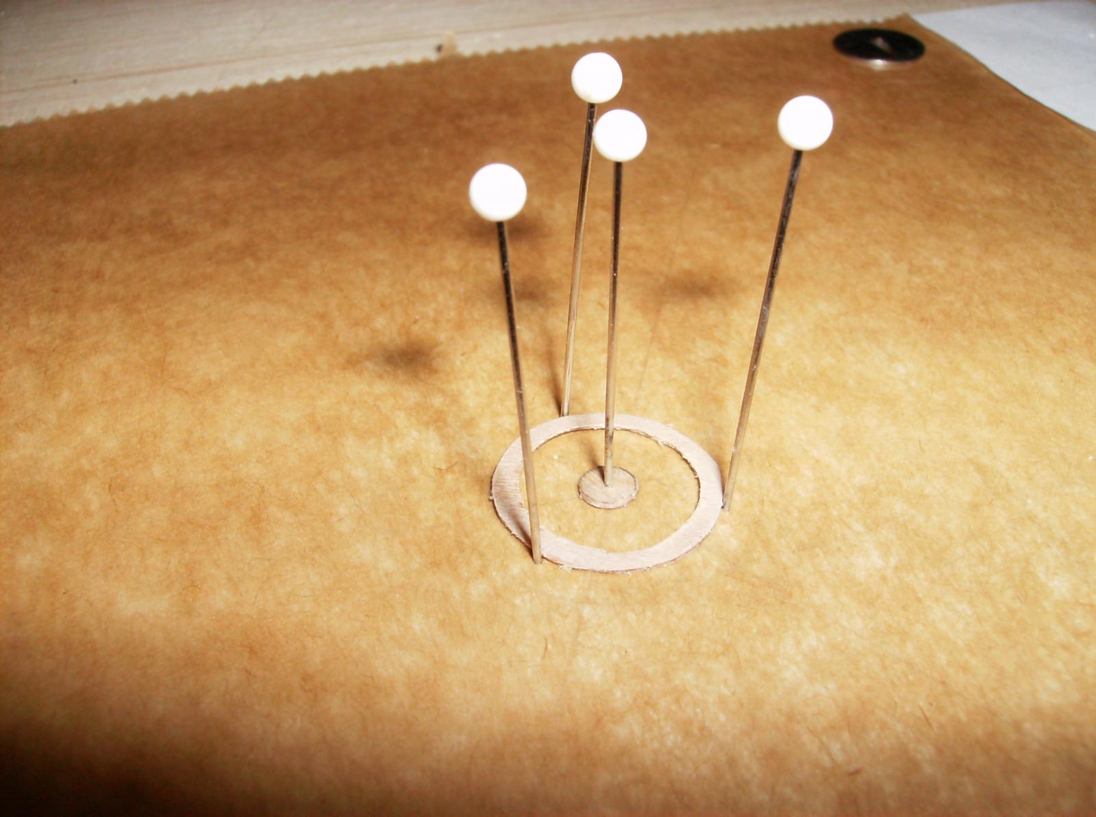
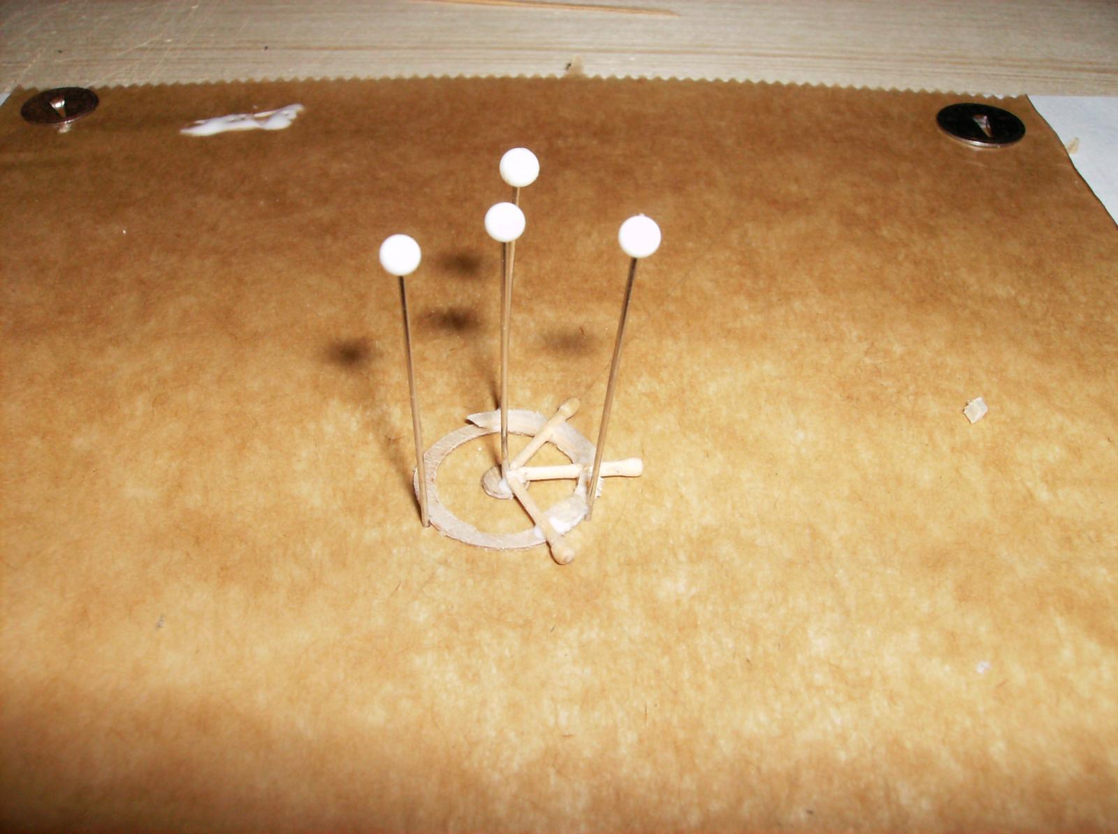
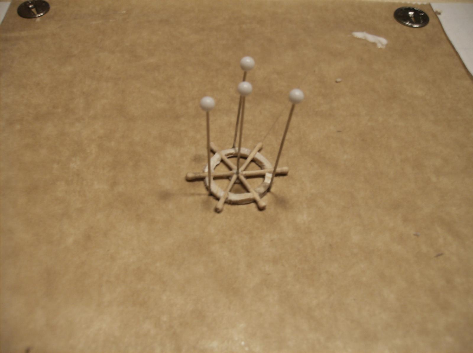
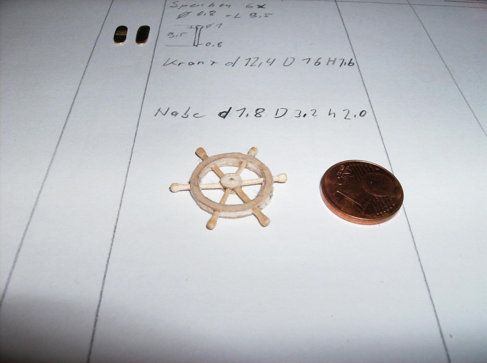
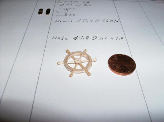
Hi again Nenad So, here is another option to make the steering wheel. For the outer rims and center use a ring of 0,4mm plywood, the spokes can be turned as from Archjofo shown, and the space between the spokes and rings can be filled with balsa wood. This makes it less complicated, the wheel for the RIGI was made that way. Hope you are not bad about some pictures........... Regards Gerhard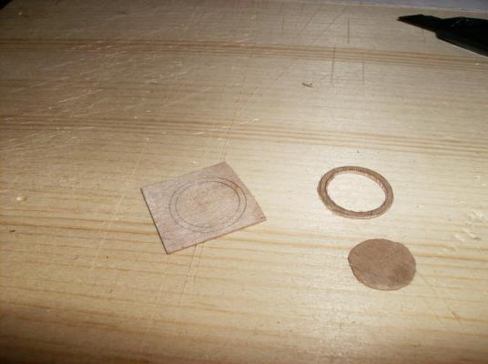


- 4,152 replies
-
- 11
-
-
- cutty sark
- tehnodidakta
- (and 1 more)
-
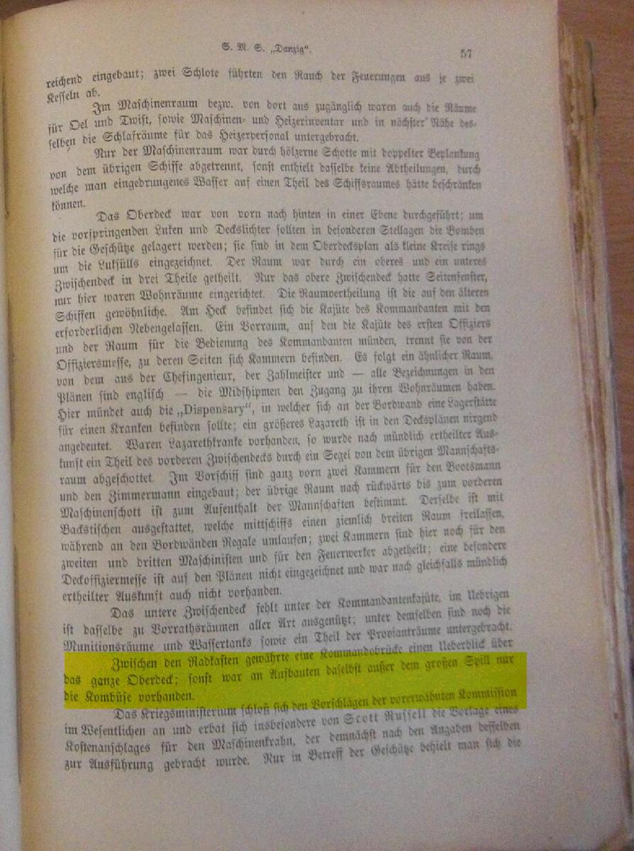
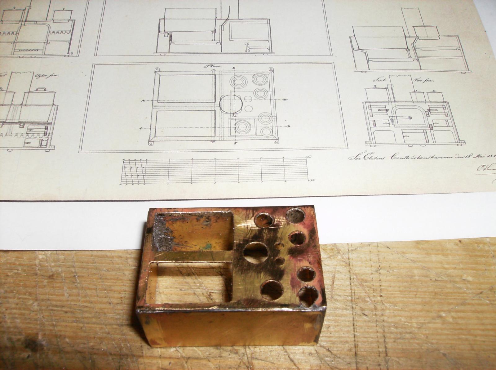
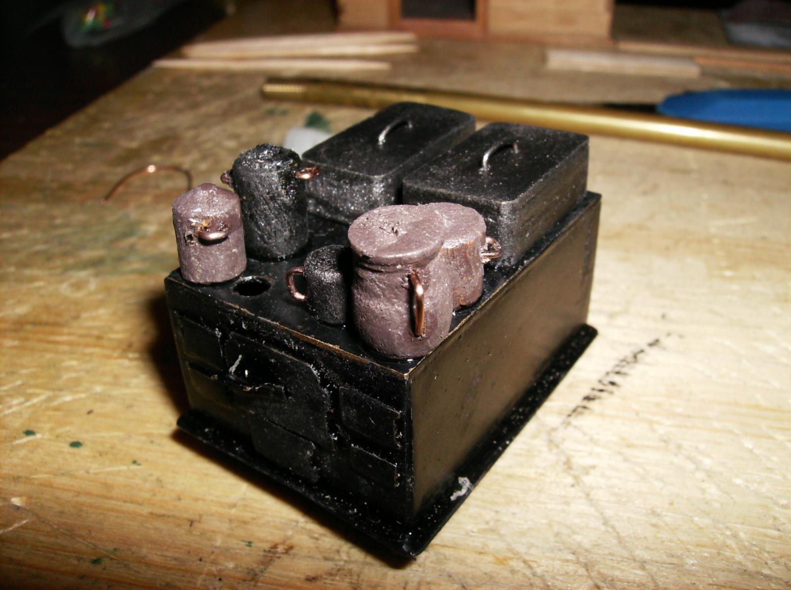
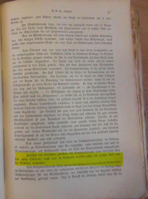
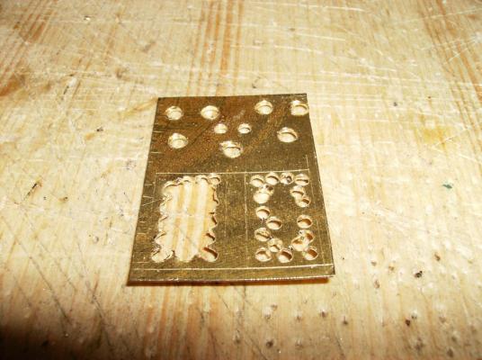
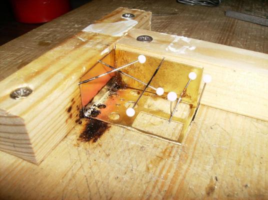
Hello once more.............. As I wrote above, here comes the first part of the cookhouse. This will take longer than the things before, it was the largest part I made for the SMS Danzig until now. As KOCH 1895 wrote, the ship had no deckhouses exept the cookhouse, see the yellow marked part at the page from "Beiträge zur Geschichte" First thing to do was the stove. As I mentioned in the first post this thread, there are no plans to get, so I had to build the stove first, and then the house around it. Plans for stoves are to find at the danish Rigsarkivet https://www.sa.dk/ao-soegesider/billedviser?epid=4782656#189070,31896806,around 130 different plans there! This includes also distillery ovens, for the preparing of "fresh" water out of sea (salt) water. Started with a sheet of 0,3mm brass, marked the different cutouts, and drilled a lot of holes The recangular cutouts were filed to their final size, and the different parts soldered together The basic body of the stove, the plans from the Rigsarkivet above, not shure what plan I took............... (Sorry for my short brains !) Different doors are soldered to the body Baseplate and stands added and finally all painted with black Revell paint, the paint was still wet as I took the picture, so it shines too much Some pots and cans added, they are made from wood, the cans from boxwood, the rectangular pots from balsa. The handles are bended pieces from 0,3mm copper wire. Regards & thanx for watching Gerhard, have a nice day!

- 108 replies
-
- 15
-
-
Cutty Sark by NenadM
Gerhardvienna replied to NenadM's topic in - Build logs for subjects built 1851 - 1900
Hi Nenad Great work so far, the rails look really good! By doing the wheel, take a look at my SMS Danzig report, how to make the spokes. http://modelshipworld.com/index.php/topic/12842-sms-danzig-1851-by-gerhardvienna-radio-150-scale/ The method I did it, was shown from Archjofo in his La Creole building report. The outer rim can be done even in other ways. The way to turn the spokes is shown in post #7 in my report. Best regards Gerhard- 4,152 replies
-
- 5
-
-
- cutty sark
- tehnodidakta
- (and 1 more)
-
Hi Craig Looks like maybe a copy of the original austrian Unimat http://www.thecooltool.com/produkte/unimat-metalline/unimat-ml-6in1/ I own the first red/black version of that machine, good for not so exactly things, but not really exact to work with. Regards Gerhard
-
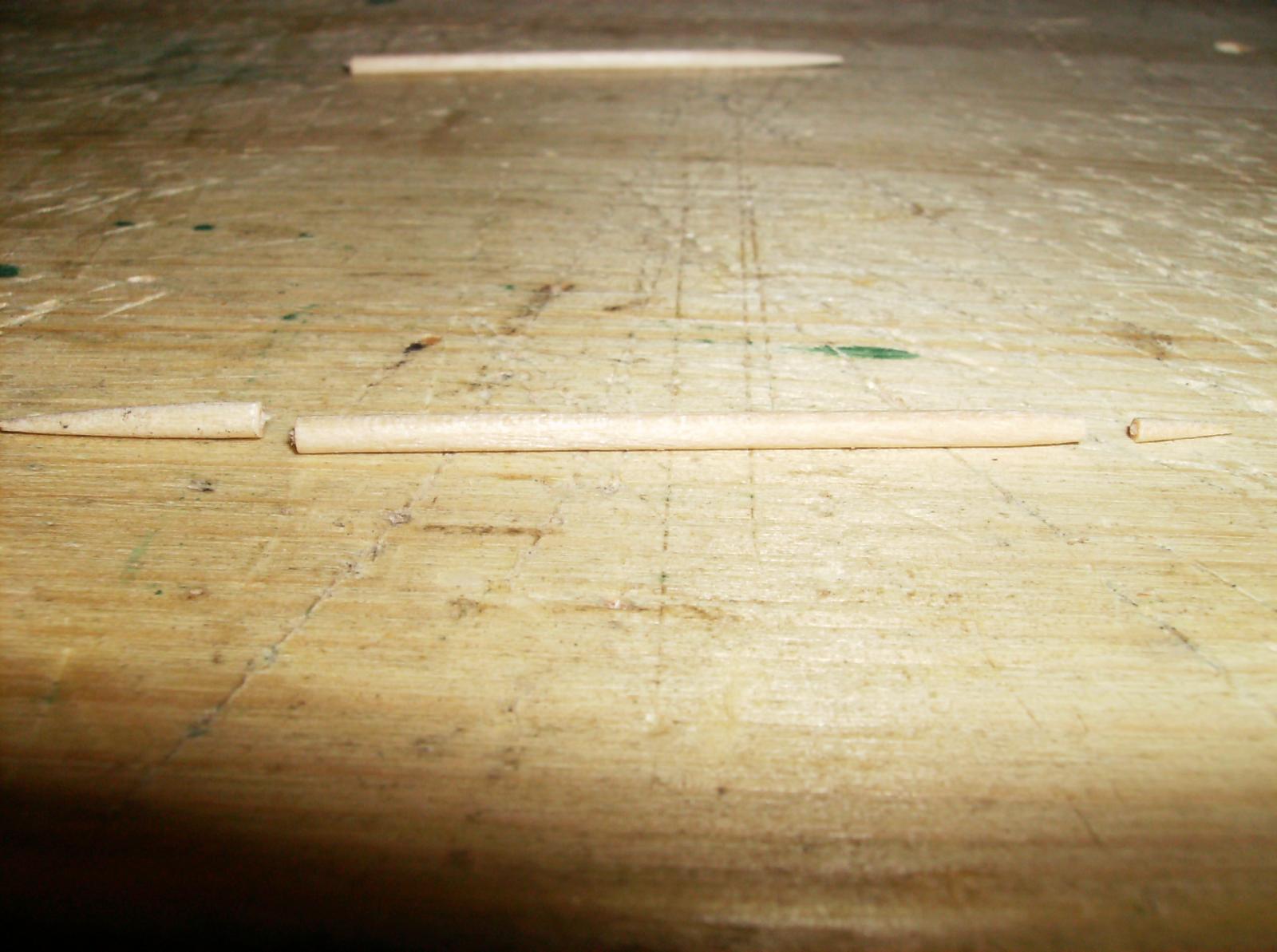
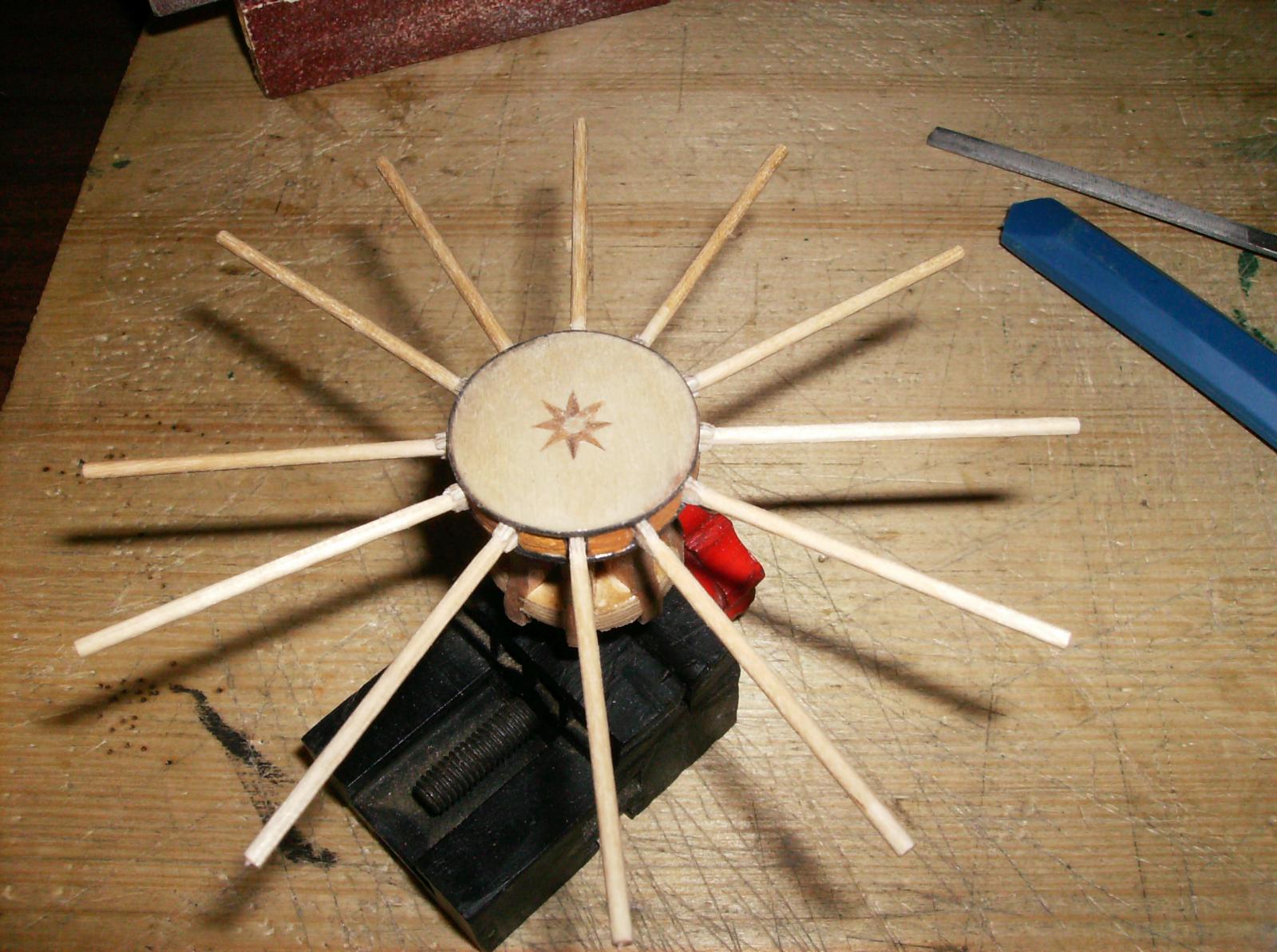
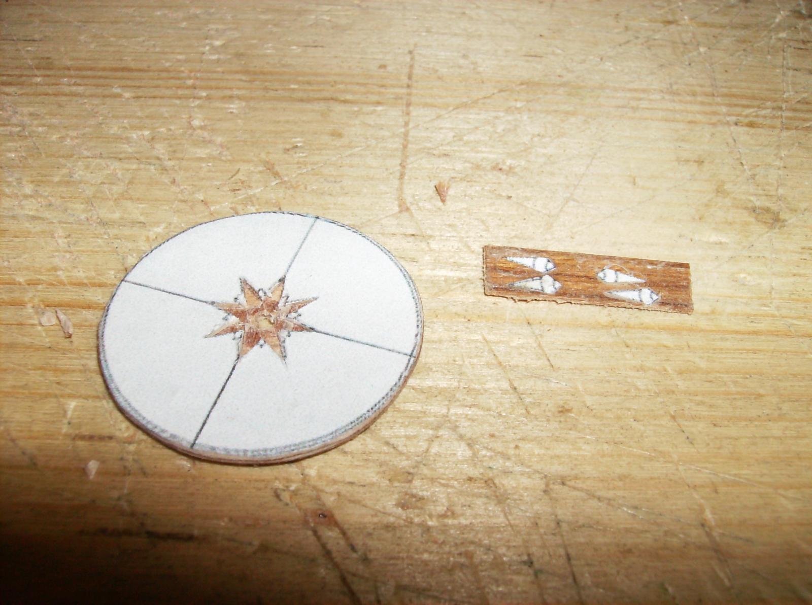
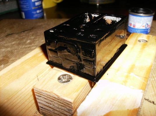
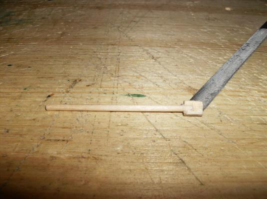
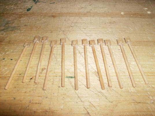
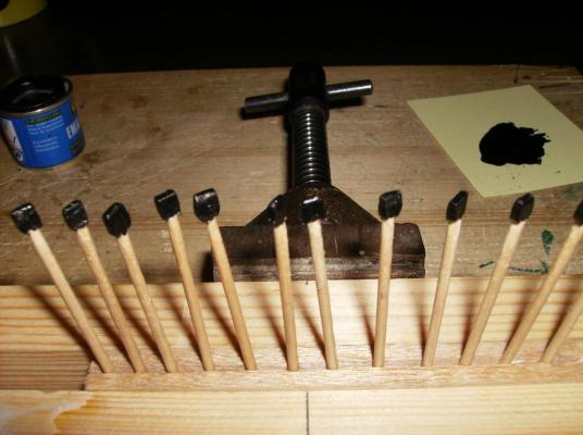
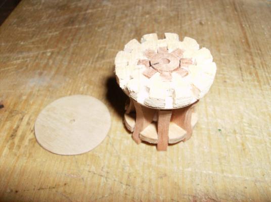
Hi Paul Thank you, and all others for your nice likes! The inlay work was the first, I have ever made. It took me more than only one attempt, to make it, but it was worth that work. The gun carriages had so many small parts, even this took a lot of time, but they had it all on the original guns. Even the barrels will be detailed, more about that, when I will cast them. Well, here comes the last part of the capstan, the spokes. I used 2mm round toothpicks as basic material and cutted them to 60mm length Then I glued small pieces of 2mm thick plywood to them 12 Spokes made A little test, they fit! As last step painted the square ends with black Next to show is the cookhouse, a lot of pics................... Regards Gerhard


- 108 replies
-
- 11
-
-
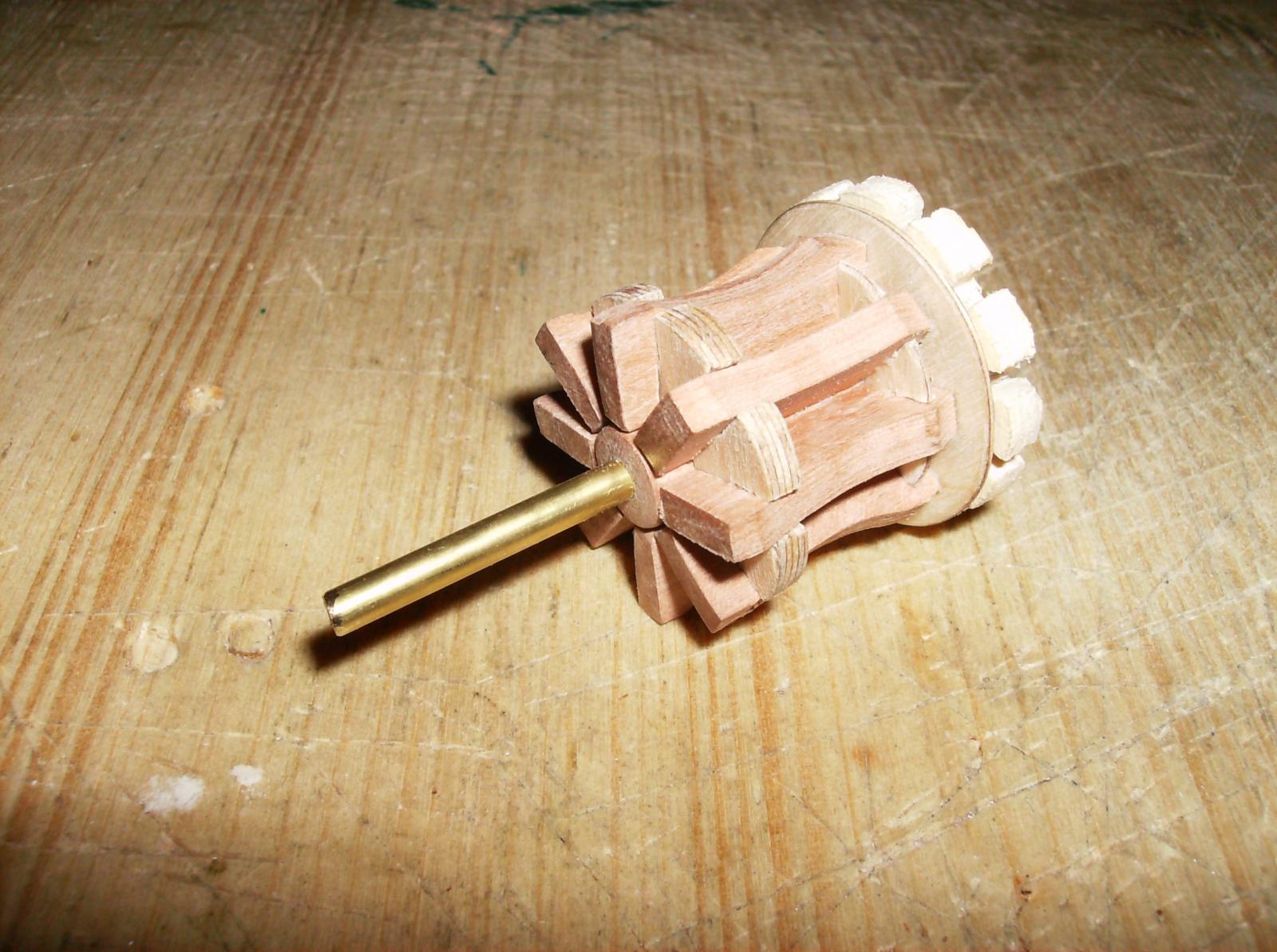
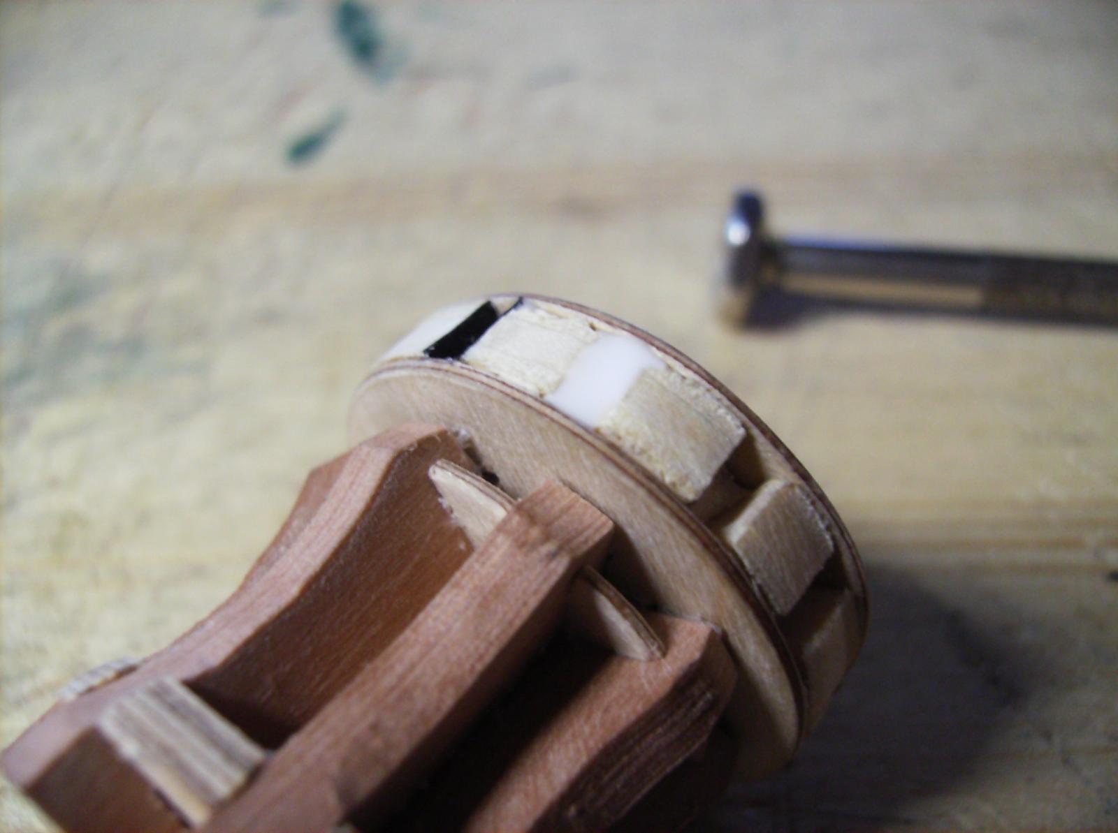
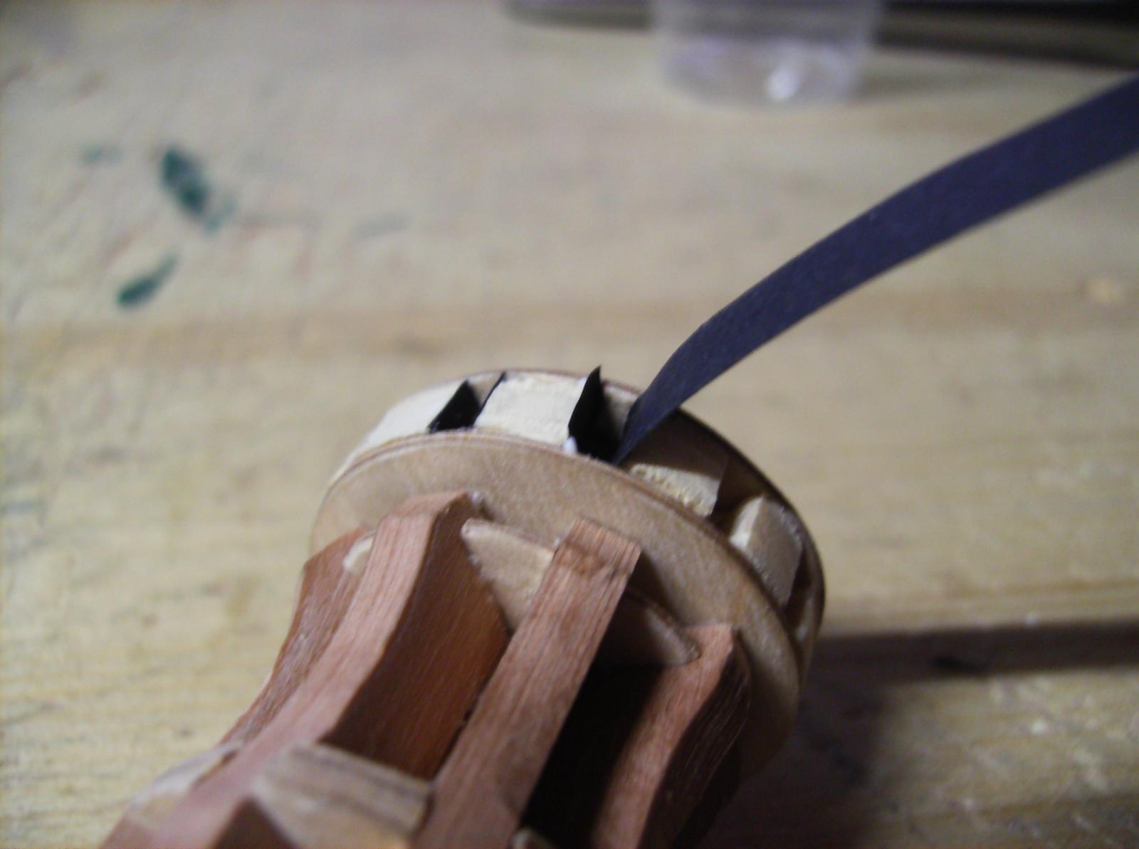
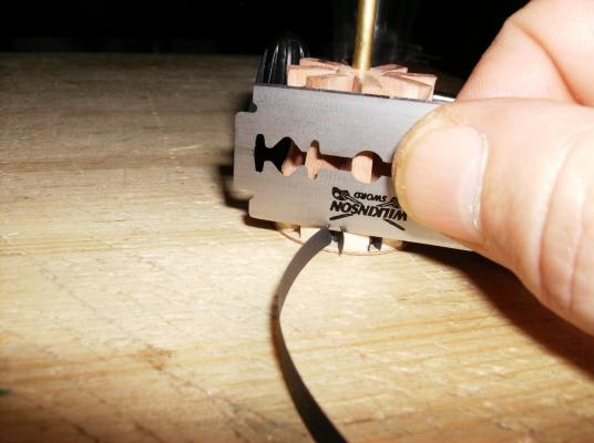
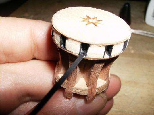
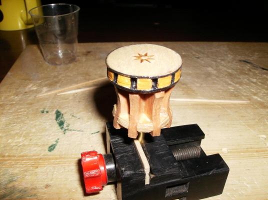
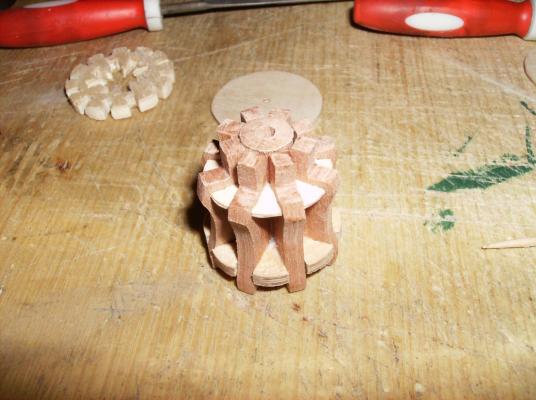
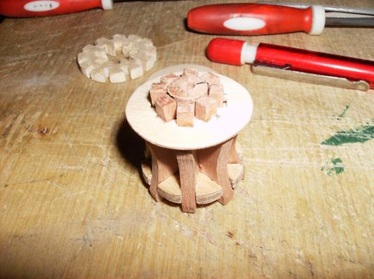
Just on the way..................... Thank you all for watching, especially to Tadeus43: I plan to bring the model to Gdansk for the ships 170th anniversary, in late 2021, if I`m ready with the build! She MUST see "her own" water! So, here comes the next parts of the capstan. Head disc layed on top for a test Now it comes to the center hole. A brass tube of 3 mm outer diameter is set into the hole, the tube must fit with strength, this is important for the next step! Upper end of the tube sits equal with head of the capstan without the head disc. No worry about the cleaves, they are hidden later with the head disc! Capstan is clamped to the late`s chuck for a last grinding. This step gives the correct shape to the different discs, especially the lower disc must be a bit bevelled. Now the head disc is glued to the capstan, the center hole is closed with a piece of toothpick. The next four pics show the former progress. I took stripes from black cardboard and glued them into the square holes Also the iron rings around the head are made from cardboard. Regards Gehard


- 108 replies
-
- 12
-
-
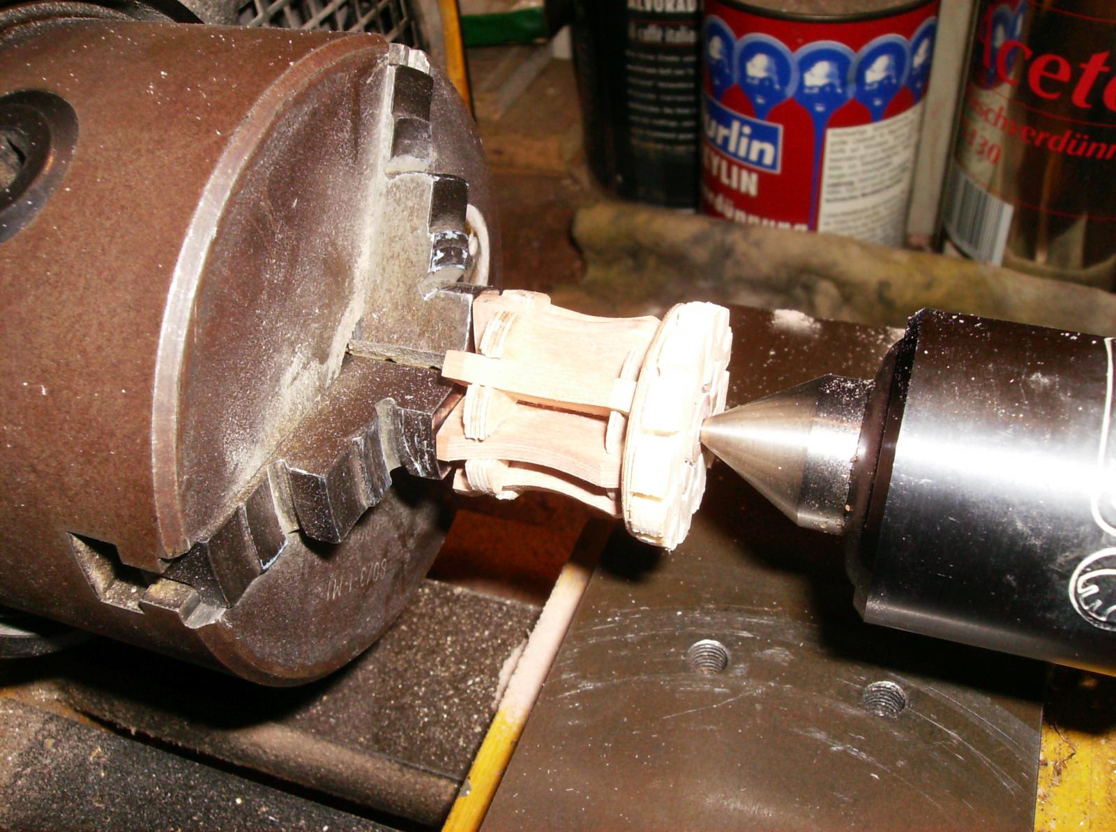
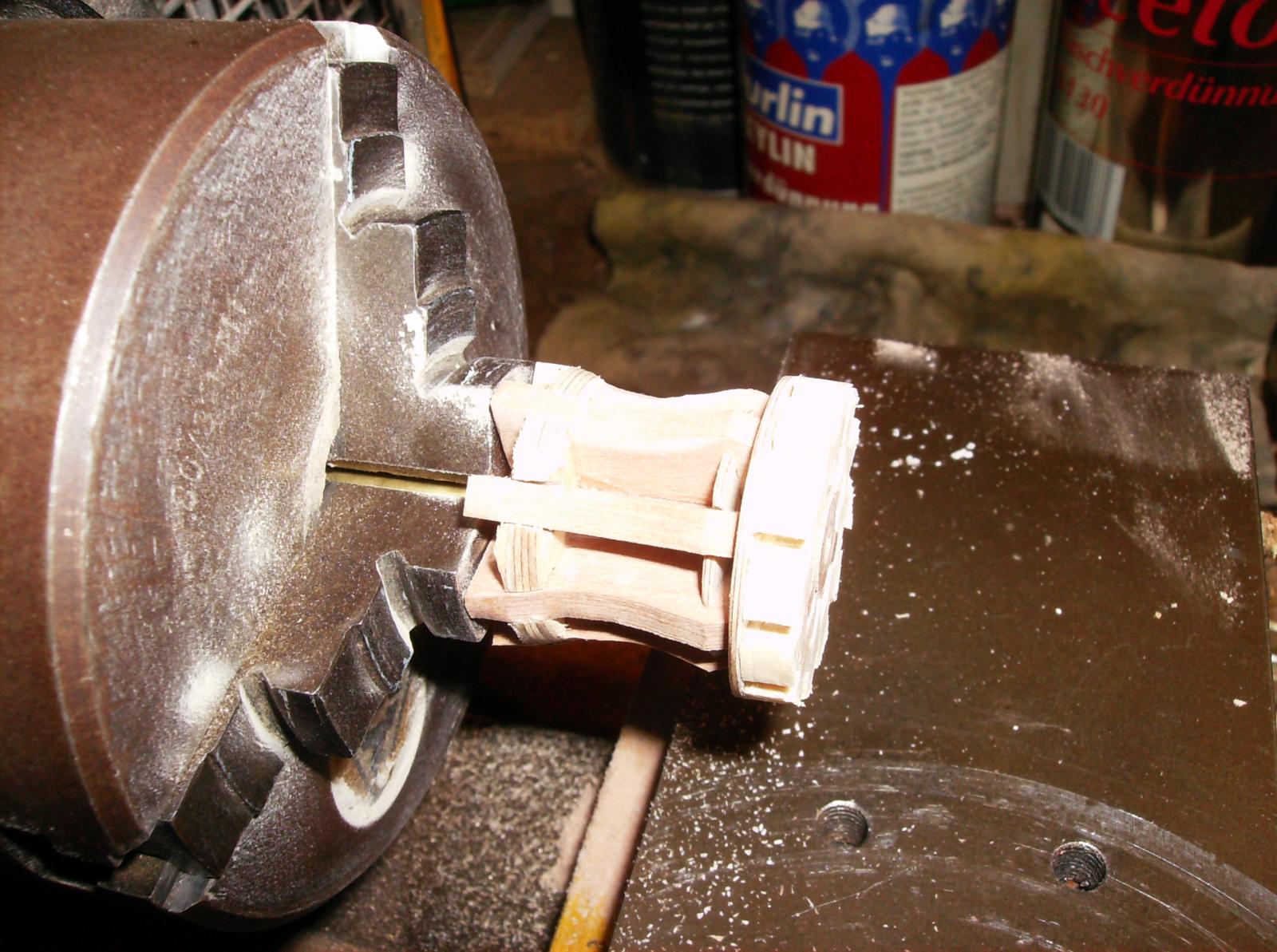
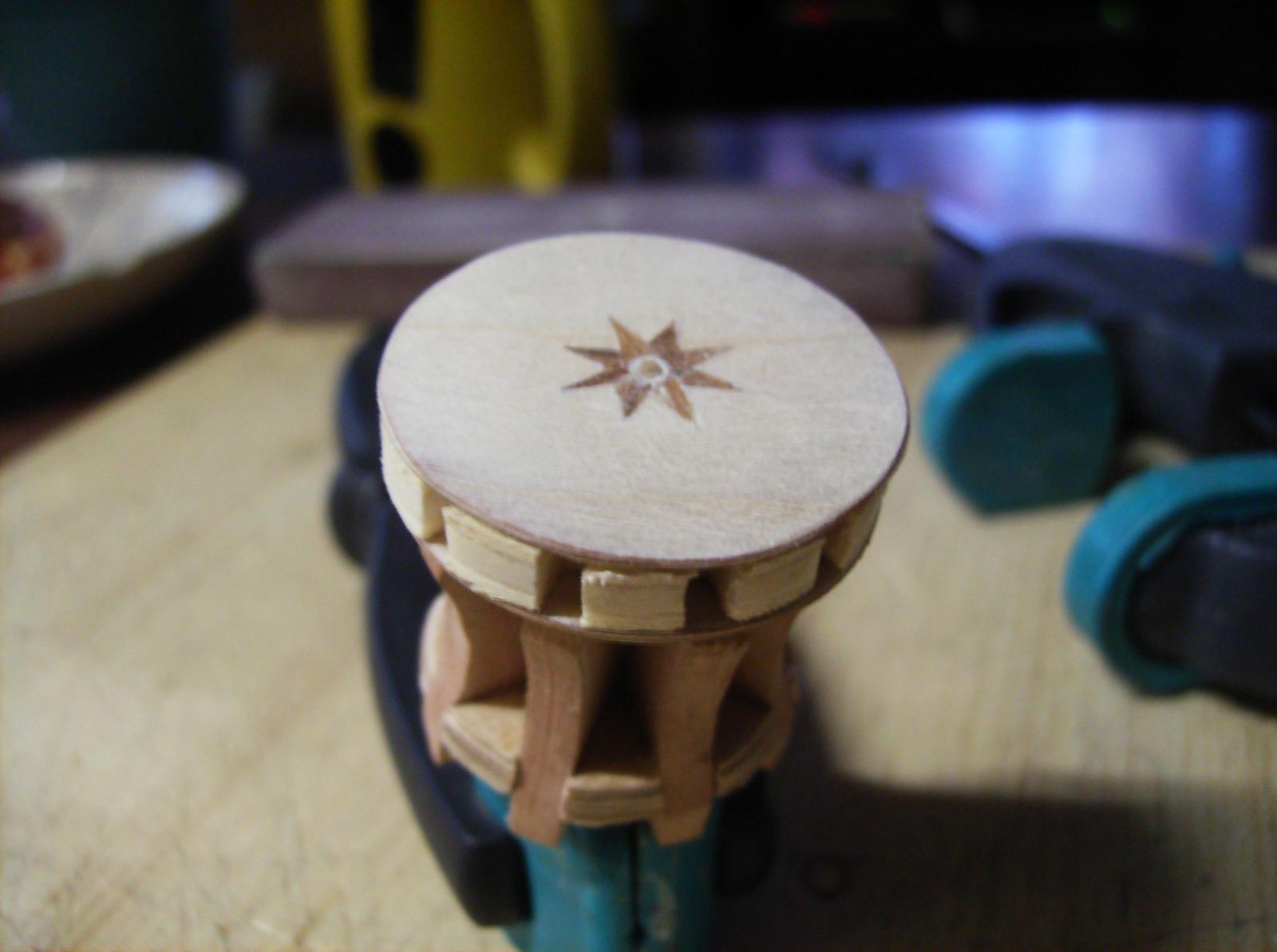
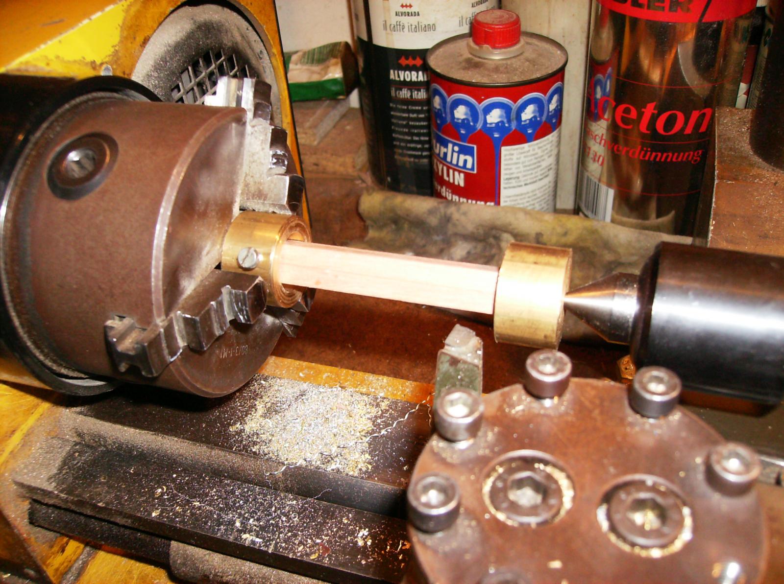
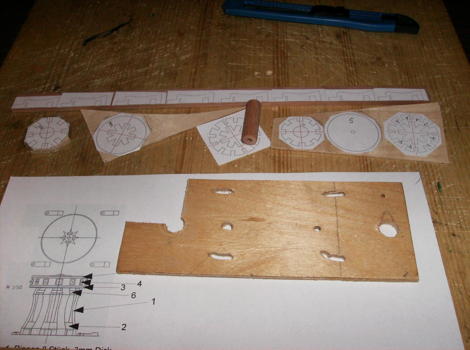
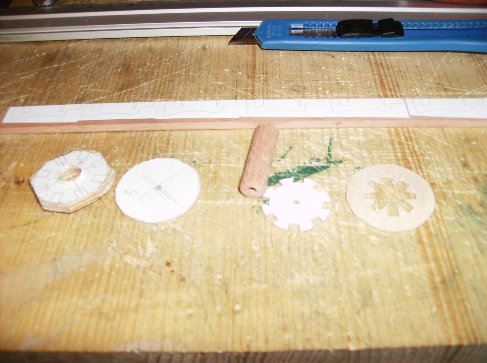
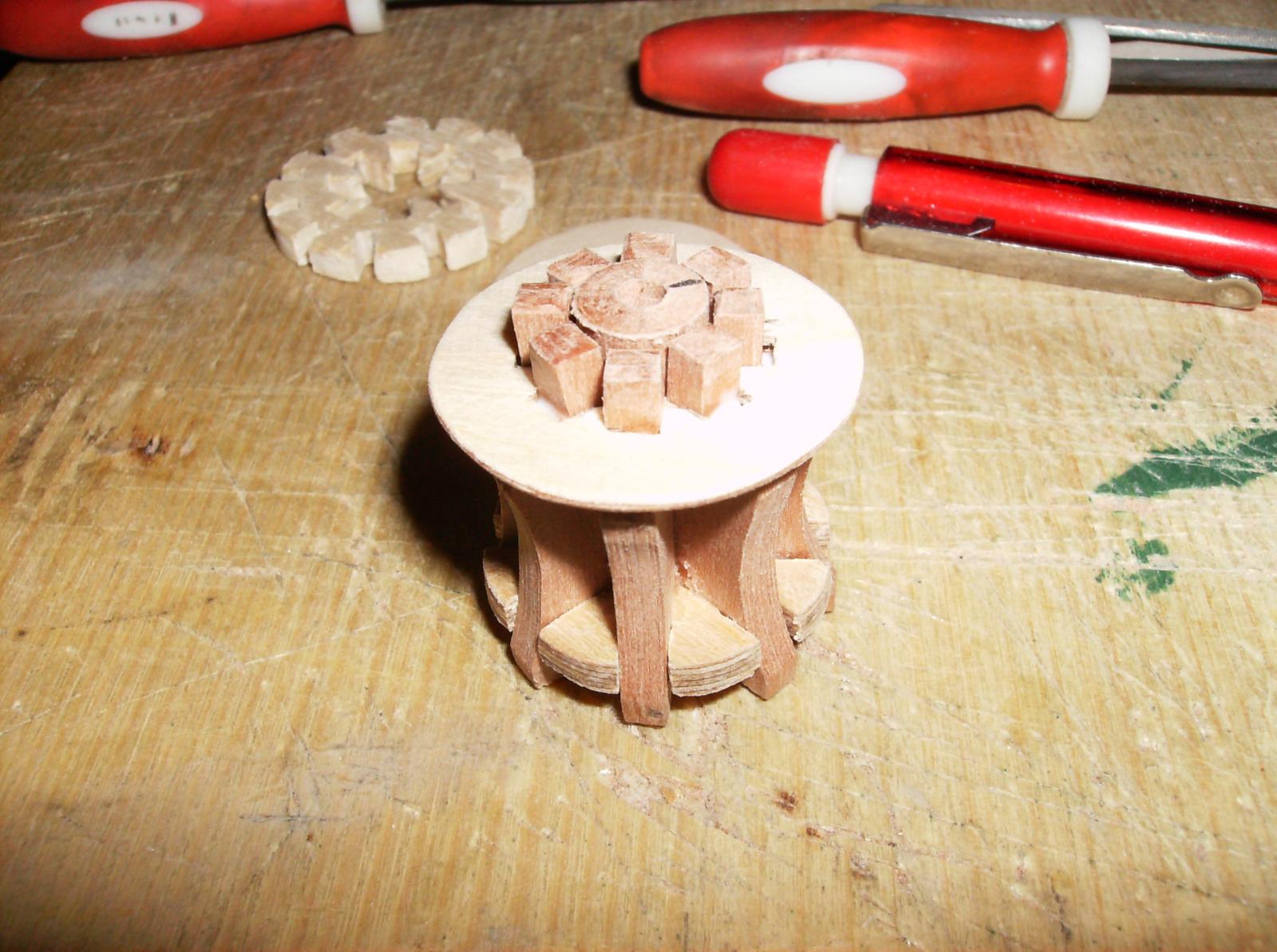
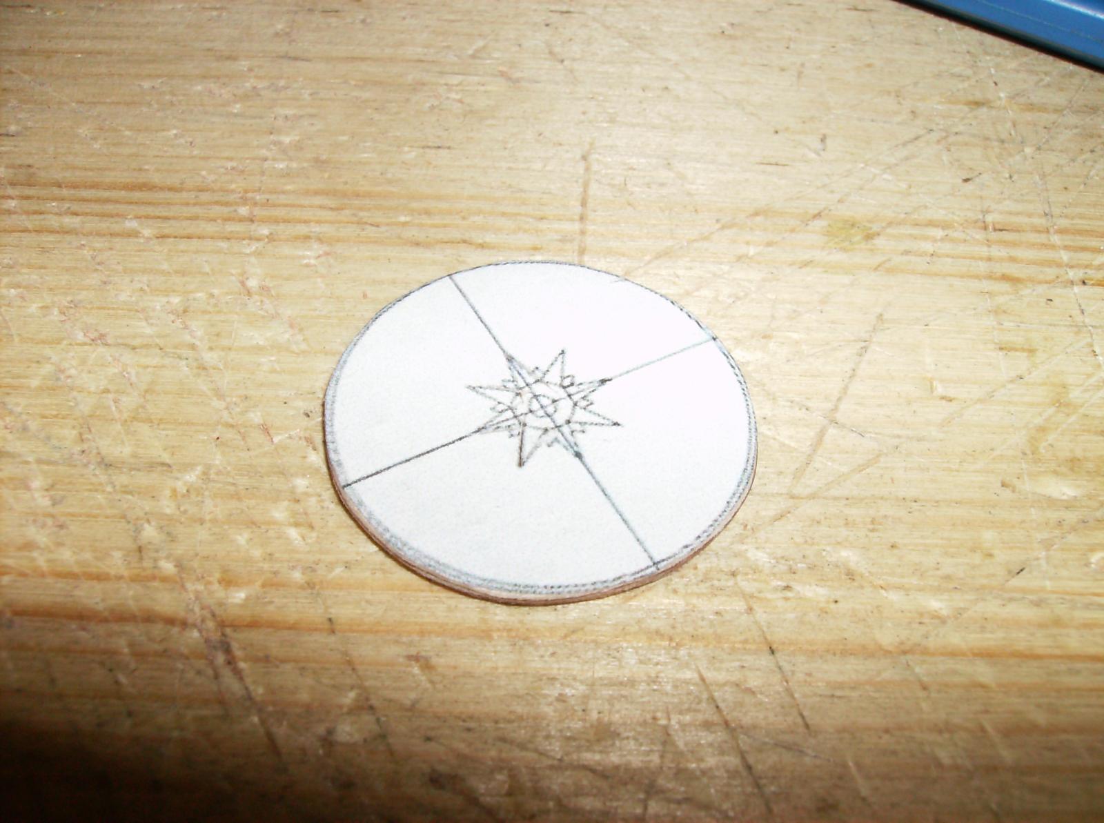
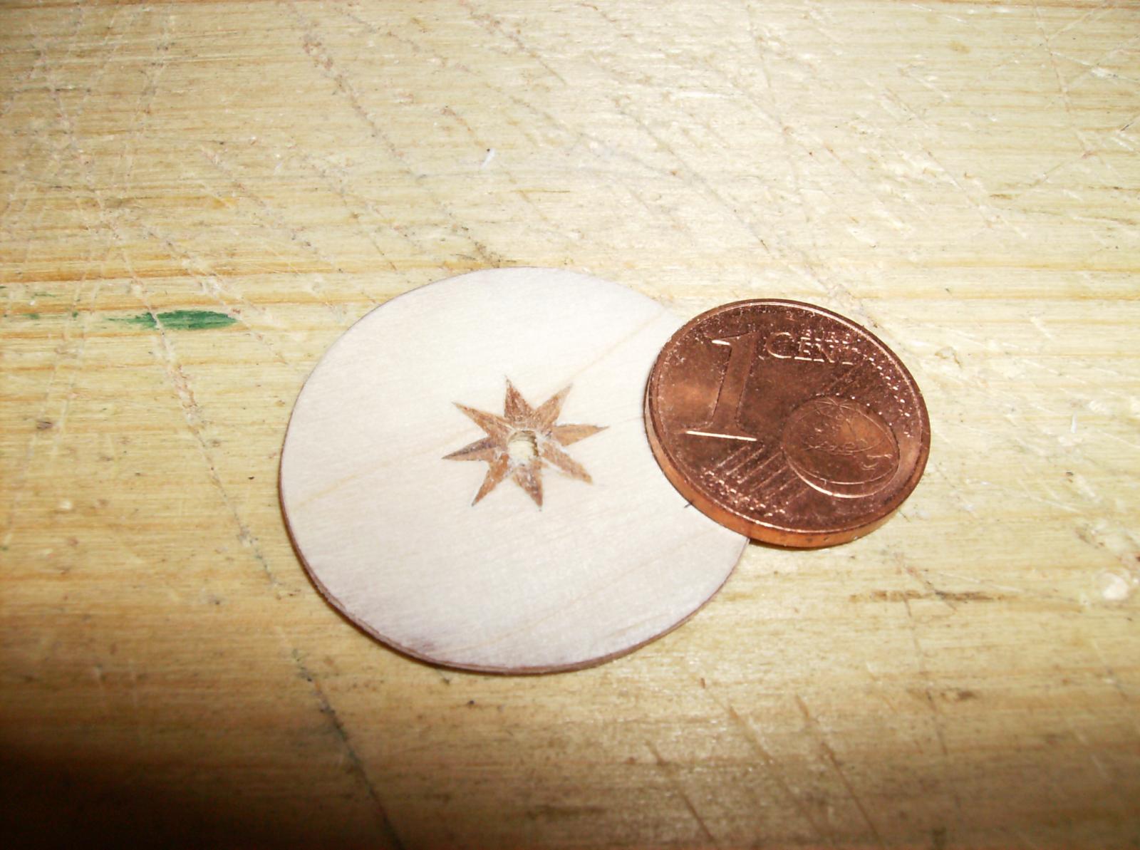
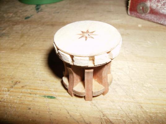
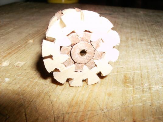
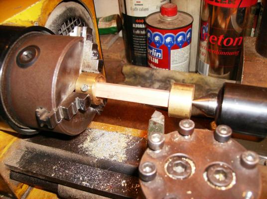
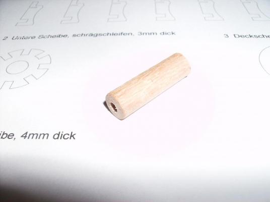
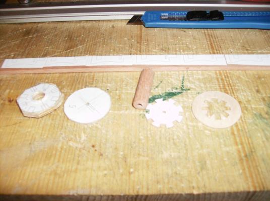
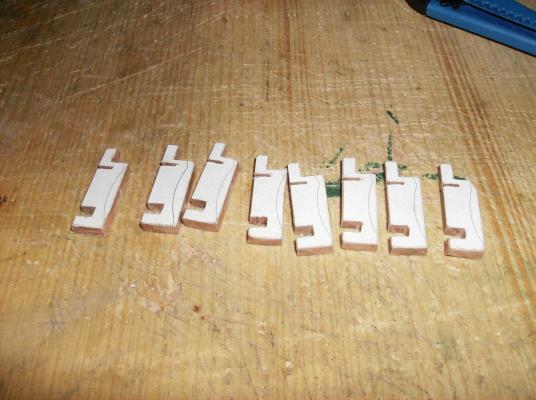
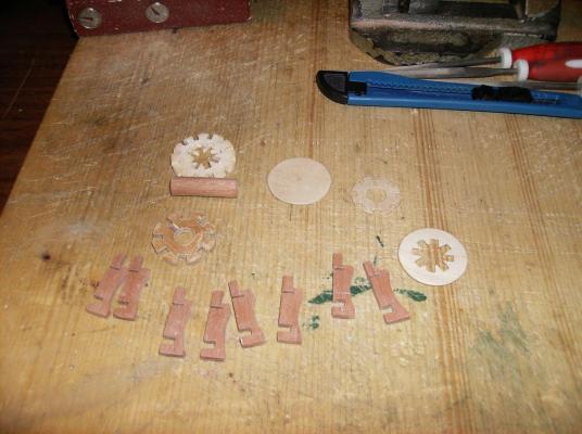
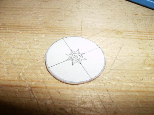
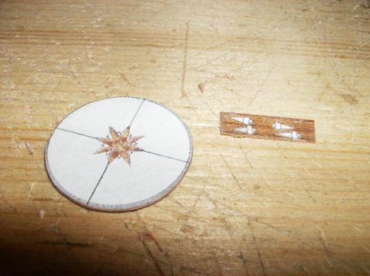
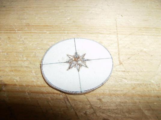
Hello Mark Thank you! This serial works must be done, but it`s never boring for me. It takes hours to produce all that stuff, but the original guns had it, so it must be there at the models. And now to something completley different ........................... Not only brass parts are done, some wodden things too are ready for the deck. First is the capstan, I used some "scrap" wood for that little thing. Spill 000 DANZIG.pdf Whoever wants to build it, please feel free to download the pdf file, it is in 1: 50 measure by printing out in original size. Round turning of a piece of pear wood, also boxwood would be good for that. After turning drill a hole over full length, I used a 3mm drill for that step, What the hole is needed for, will be shown a bit later. All parts printed out from the pdf, and used as templates. The printouts were glude to wood in named thickness All parts were cut out and grinded/sanded to their final shape Lower parts assaebled Thick upper disc mounted The head disc with cutouts for inlay work, some of the inlays shown in second pic on right side Inlays glued to disc, then sanded very careful. Inlays are just 1/10th mm thick This was the first part for the capstan build, will be continued a bit later............. Thanks for watching and your many likes Regards Gerhard


- 108 replies
-
- 12
-
-
Hi druxey Maybe I did overread this, what measure do the hulls planks have? This looks so incredible thin but strong too. Great work. Regards Gerhard
- 641 replies
-
- 3
-
-
- greenwich hospital
- barge
- (and 1 more)
-
Hi Nils Old watches, Video recorders and other things are very useful sources for small parts. I almost "collect" those things just to get everything out of them. Had a good look at the photo you mentioned, this is a monster! But I like this big ships. Best regards Gerhard
- 2,625 replies
-
- 4
-
-
- kaiser wilhelm der grosse
- passenger steamer
- (and 1 more)
-
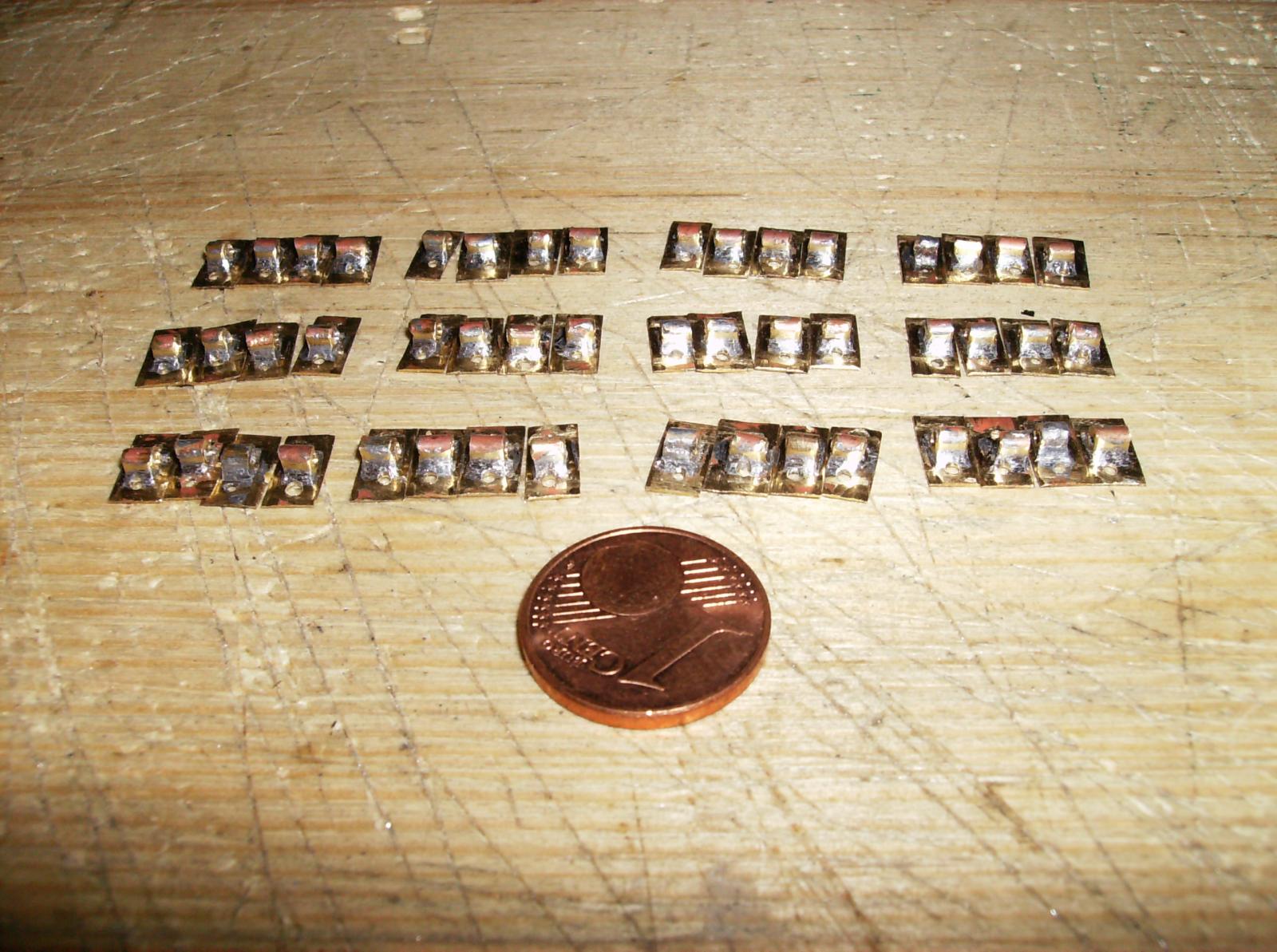
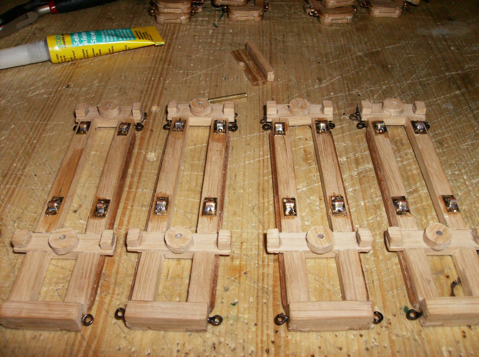
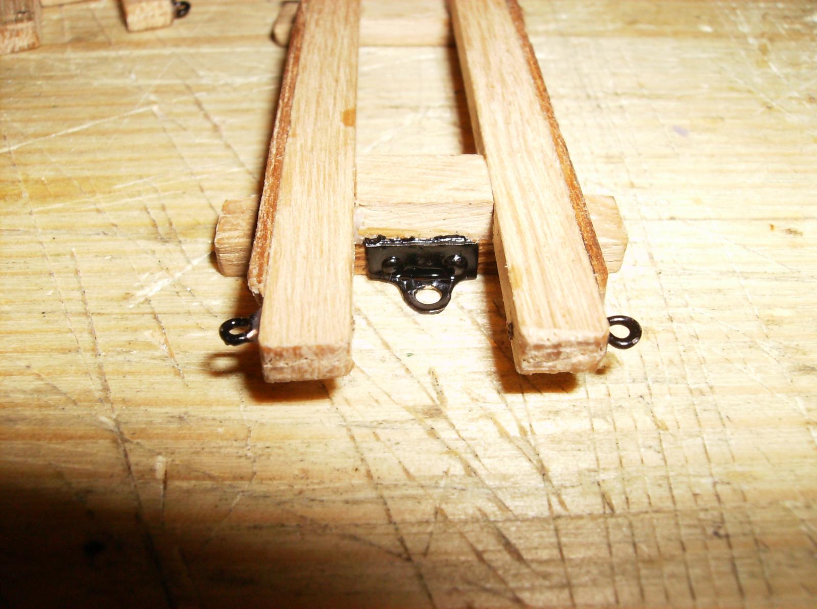
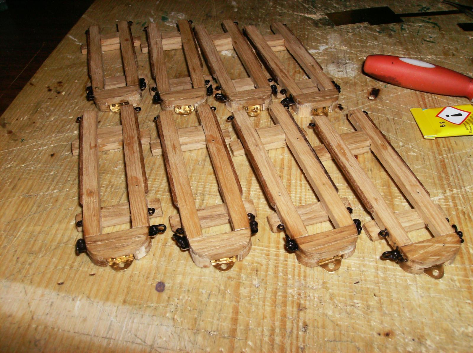
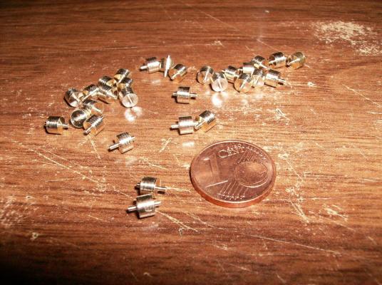
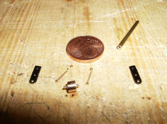
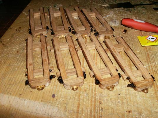
As we go on with the review, here come the next few parts First the eyelets on the bottom of the lower carriages, they are simple soldered brass parts. Also the front wheels had to be made. The wheels are turned from 4mm brass rod, they measure 3,8mm diameter, and width of 3mm, the axels are 0,8 x 0,8 mm. Uper carriage prepared for wheel mounting, the upper holes are drilled a bit larger. This is necessary to set the holder plates at a correct angle. Mounting setn for one side wheel mount: 2 holders, 2 screws & nuts M0,6, 1 roller. The small brass tube was used as a wrench. The tube was slightly flattened, then I use a really small amount of silicone for sanitary use inside the tube, and fixed the hexnut into it. This holds the nut as long as it is needed, and releases it when all is fixed. Right side done. Both front whhels mounted, all that was made for 12 gun carriages................. Best regards, thank you for all your "likes", and comments Gerhard


- 108 replies
-
- 14
-
-
Hi Nils Did you have a look at STEBA? http://www.steba-modellbau.de/Katalog/katalog.html They have a lot of gears metal or plastc, maybe you can find something for the winches. Other sources http://www.mikromodellbau.de/Shop/volltextsuche.php , http://shop.kkpmo.com/index.php?cat=c21_Zahnraeder-und-Triebe-Zahnraeder-und-Triebe.html Regards Gerhard
- 2,625 replies
-
- 4
-
-
- kaiser wilhelm der grosse
- passenger steamer
- (and 1 more)
-
Hi John Thank you, until now I have only made the easy things, some more of that is still coming. I have at the time no possibility for the modelships, I`m doing my home improvement. The living room must be renovated, and my store also, so all i can show at the moment is done weeks and months ago. The "hard" stuff will follow, when improvement is finished, then I will start with the hull, deck, masts & rigging. Even the gun barrels must be made, so it`s alot to do still. But I have even more for the review, next things will follow tomorrow. Regards Gerhard
-
Hi Davemc You can hide the pinholes by using wooden nails after full planking. This will give the hull a more original look. Using woodfiller is not bad for the first planking, so you can create a very clean surface for the visible planks, well done! Regards Gerhard
- 25 replies
-
- 2
-
-
- snake
- caldercraft
- (and 1 more)
-
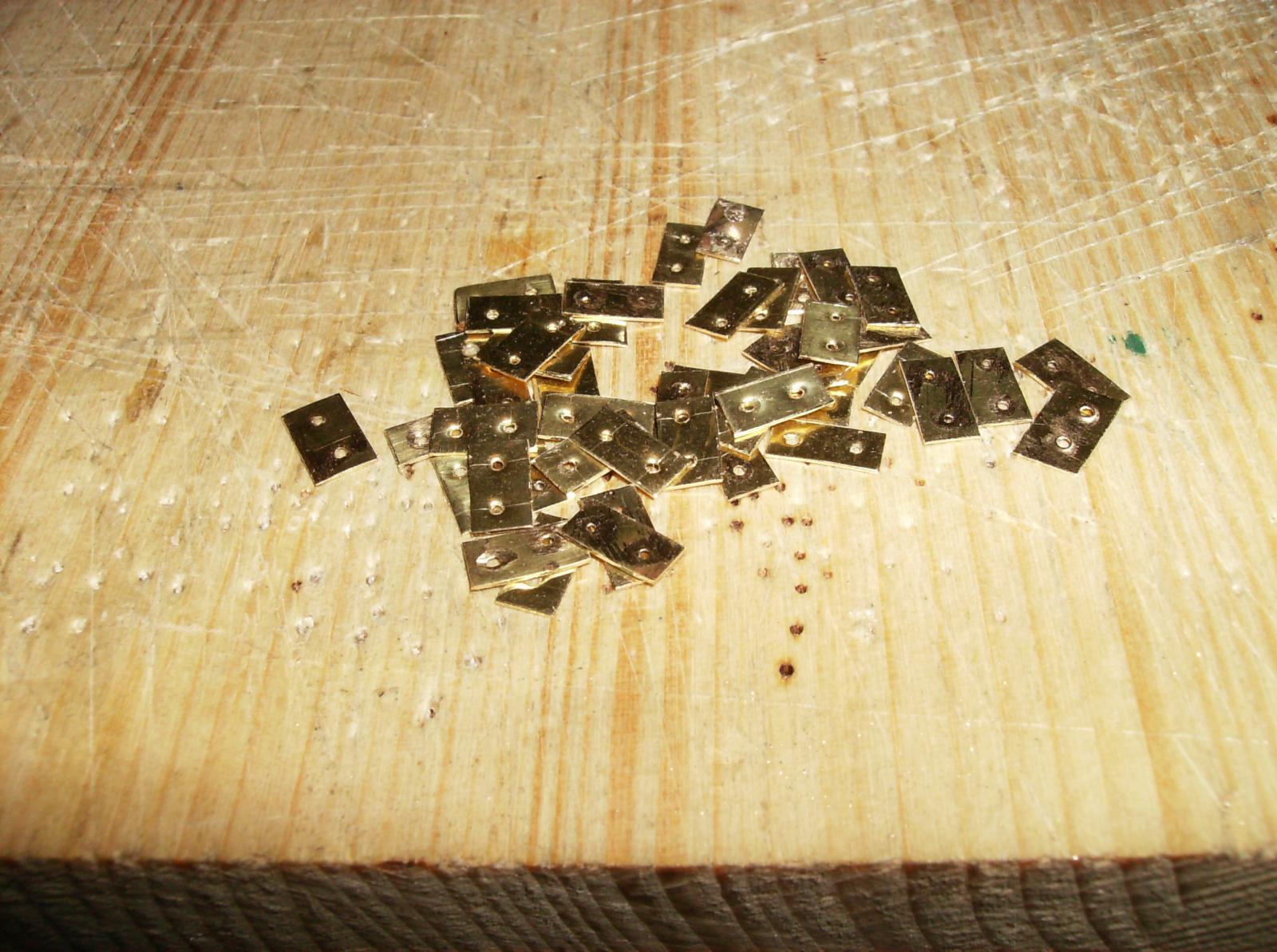
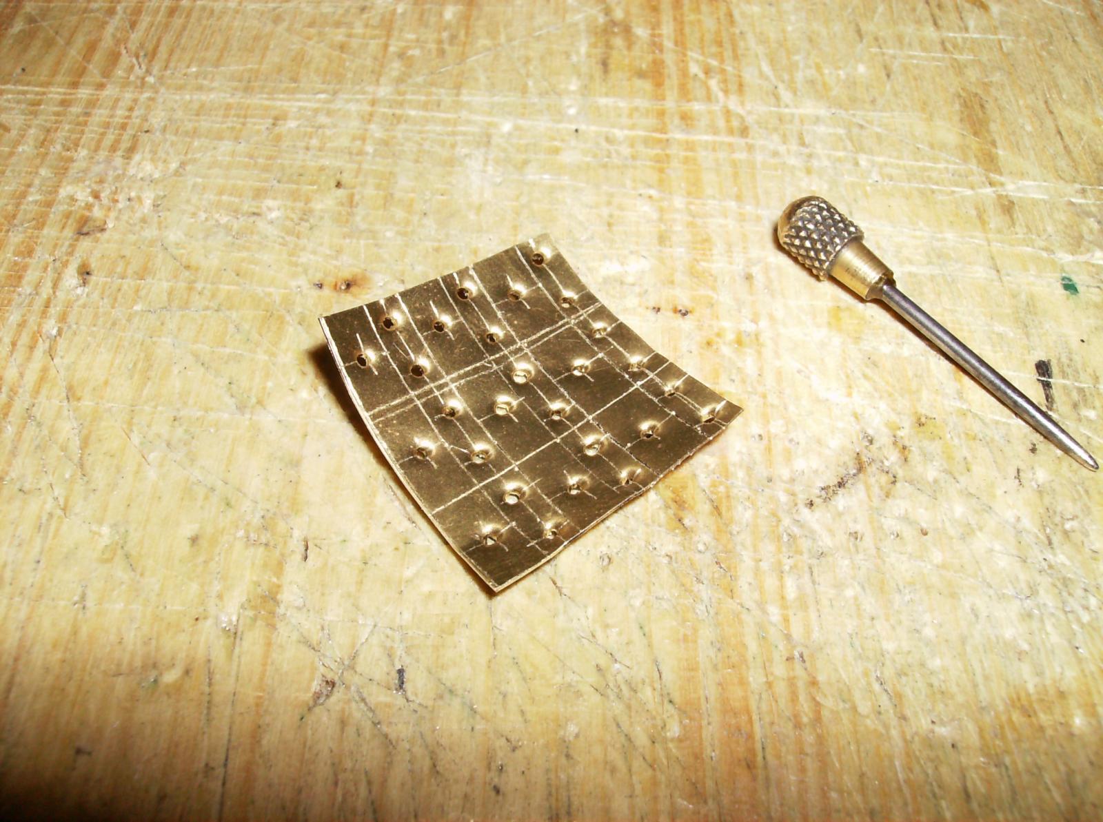
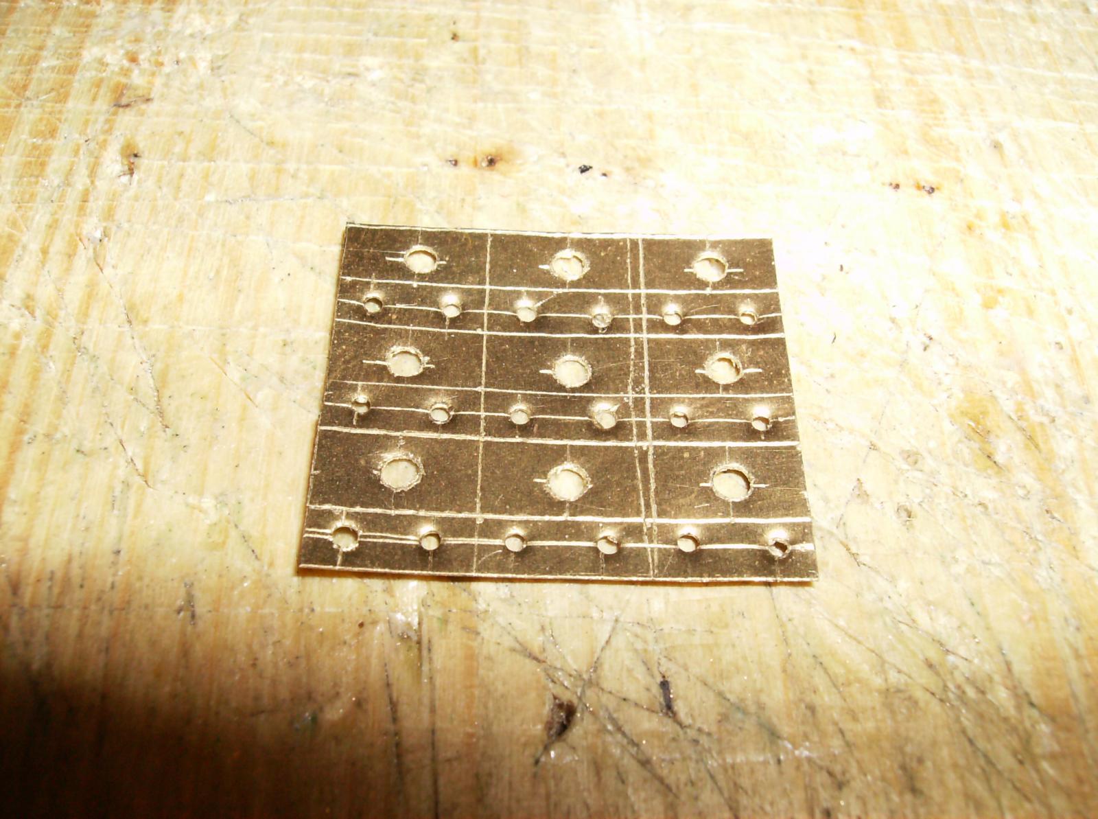
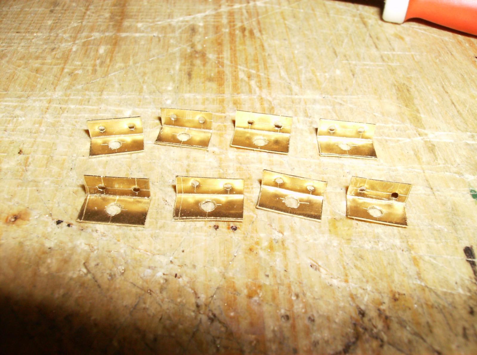
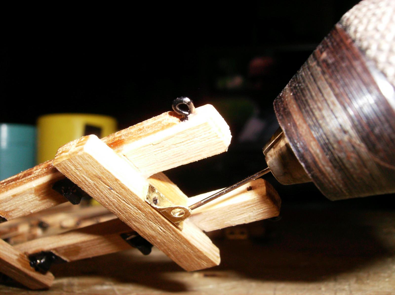
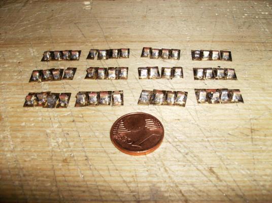
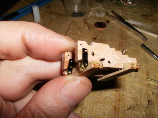
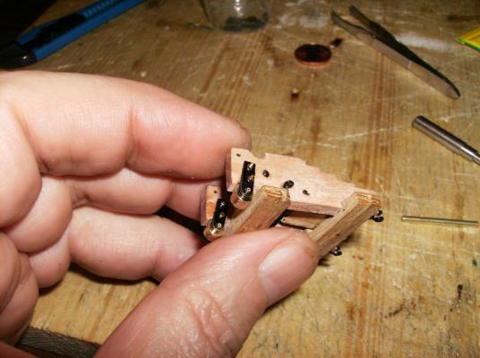
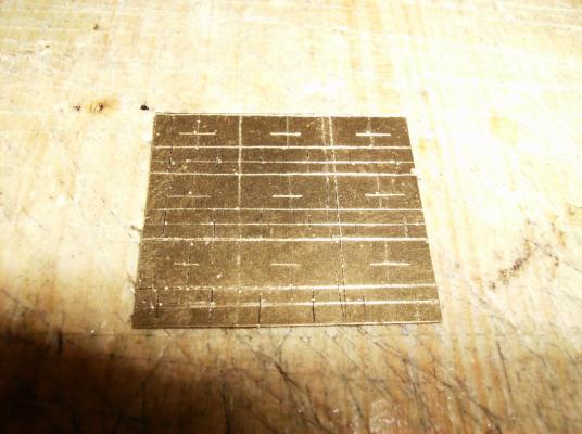
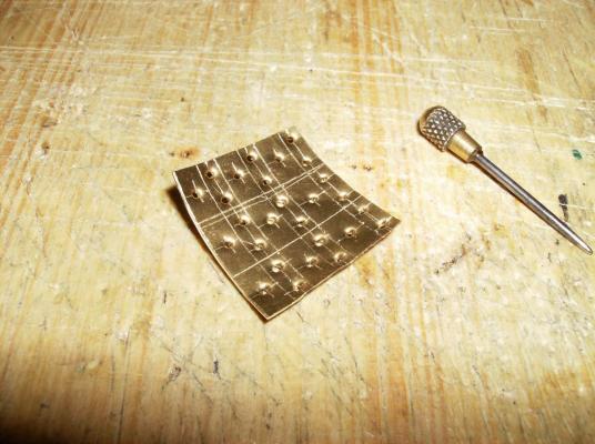
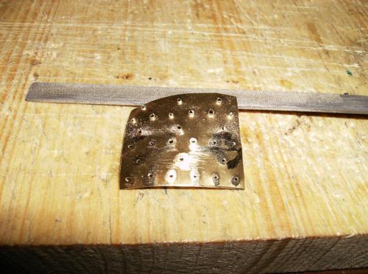
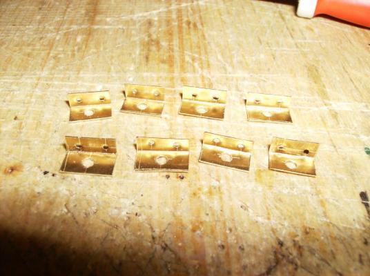
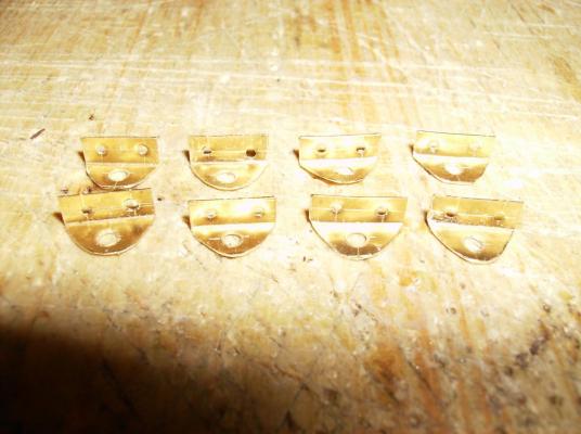
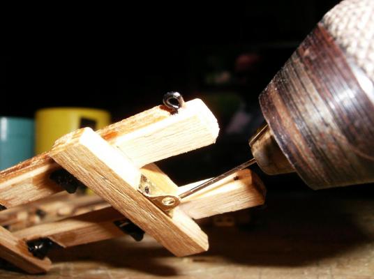
As I wrote above, there were more of mass production parts. Next to do were the pivot holders to the lower carriages. I made them from 0,1mm brass sheet. The holes were marked with a steel needle, and then pierced through The backside of the sheet lokked like this, the ridges were filed away, and the sheet bend back to flat Then opened the holes to correct size, bend the flat plates to 90° angle, and filed to rounded shape As a last step the holders were mounted to the lower carriages. For drilling the mounting holes I use a sawing needle, that does not break so easy like normal drills do. Front and rear holders have different shapes, but both are made the same way. They all are painted with black "silk type" colour, I paint mostly with Revell colours. back soon for more, thank`s for watching and your likes............ Regards Gerhard


- 108 replies
-
- 15
-
-
Hi druxey This is a great little ship, thanx for showing! Could be a model to build for me too, I`m following. I love all that gold, and the way you build the hull gives me some advise. Regards Gerhard
- 641 replies
-
- 2
-
-
- greenwich hospital
- barge
- (and 1 more)
-
Hi druxey YES! ALL of this little holes. They are needed to mount the pivot seats to the deck, and I will do that the right way with handmade nails. But as this is just a review, we will see the production of the nails a bit later, when it comes to present times. Hi Nils Thank you There are a lot more of mass production parts, must sort my pics out for the next posts. Just for the guns were around 200 photo etched parts drawn and ordered, see the drawing in post #10. All the blue marked parts were redrawn by me and ordered at http://www.0mobau.de/index.php?cPath=27&osCsid=6rqn4eikc62e5pqfpjgmc0q033. My lathe is an old Hobbymat from Eastern Germany, works well after about 20 years of use! Regards Gerhard