


Gerhardvienna
-
Posts
683 -
Joined
-
Last visited
Content Type
Profiles
Forums
Gallery
Events
Posts posted by Gerhardvienna
-
-
5 minutes ago, BANYAN said:
Hi Phillip and Gerhard, I would leave them Phil - I am pretty sure she was fitted with a feathering propeller and the pitch would have been close to zero when not needed (such as in port or when under sail alone) - depends on how you would like to depict her.
cheers
Pat
Hi Pat
This would declare why they made it that way. When there was a pitch control, so the "Zero" position will be allright for sailing! Well seen and explained, thank you!
Regards
Gerhard
- BANYAN, Philg88 and popeye the sailor
-
 3
3
-
-
Hi Philip
Looking really good!
BUT...............
I would make a slight change on the propeller, a prop with that shape will give no speed, but only swirl water. If there is a way to make the change, I would. Sorry for beeing late with that!
Regards
Gerhard
-
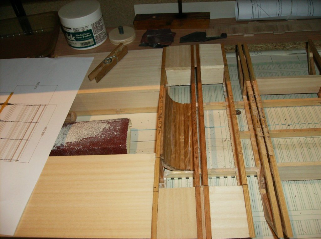
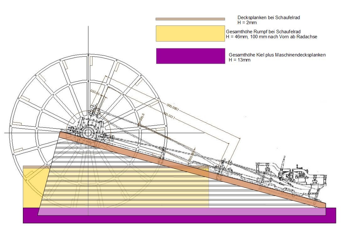
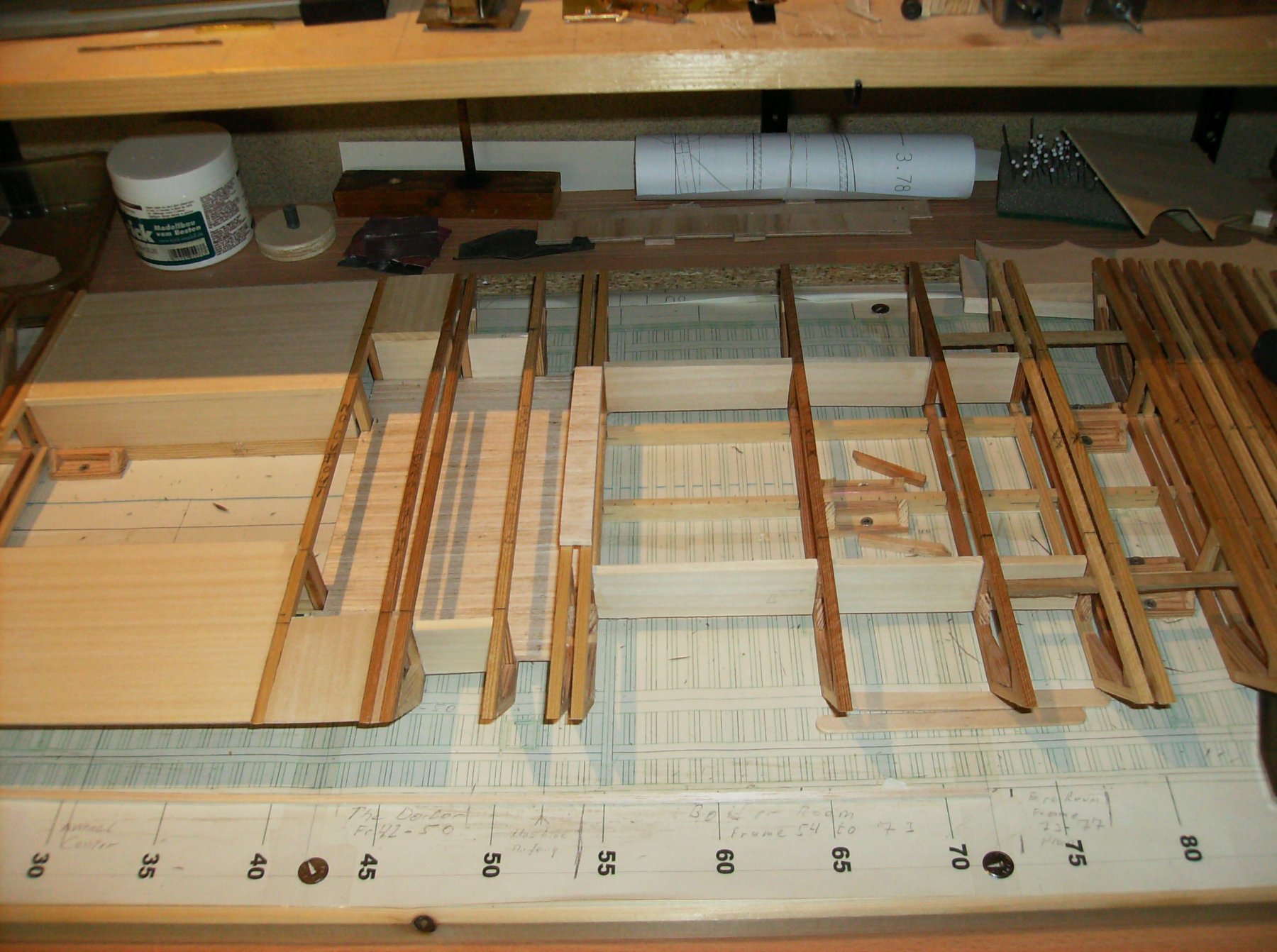
While the sanding for the cutters core I made some drawing work for the engine and paddlewheel compartment. The timbers will be made from 5 x 5mm pinewood, and they will be slotted as we have seen on the photos in eric´s (@cathead) thread https://modelshipworld.com/index.php?/topic/15945-designing-a-model-of-the-1856-missouri-river-steamboat-arabia/#comment-498868 , and on the pictures from the Cairo museum too. The attached photo shows how the timbers will be laid, but without the slots.

Regards
Gerhard
-
-
Hi Nils
Well done! With a little amount of paint they will be perfect! I like the boats.
Regards
Gerhard
- Mirabell61, Piet and cog
-
3
-
-
Hi johnhoward
Great find, this shows how large the camber was on the roof. This will be more difficult to build, but possible. As I have no parts from the superstructure premade, I can and will make it that way!
Regards
Gerhard
- johnhoward and Canute
-
2
-
-
-
Hi Nils
Great way to make the boats! They look good!
Regards
Gerhard
- Mirabell61 and cog
-
2
-
6 hours ago, cog said:
I suppose you could print the engine, if your 3D printer is up to the task ...
Hi Carl
This would not be good for a life steam engine. Too much heat, I will have to mek the engine from brass. And, my printer will not be ready for the dummy engine, lots of parts are ordered in China, as I will make the printer from "scratch" too! Maybe I`ll have another building report about that.
Regards
Gerhard
- cog, johnhoward, Cathead and 2 others
-
5
-
Hi Carl
Most of the sanding is done, just a few milimeters still left. Took me about 20 hours to get that far.............
Beneath that I work on the PC for the engine, there is a lot of planing work to make. Everything must fit well to the hull, so I will have to make some sort of dummy engine for testing, and when all fits well then the real thing.
Regards
Gerhard
-
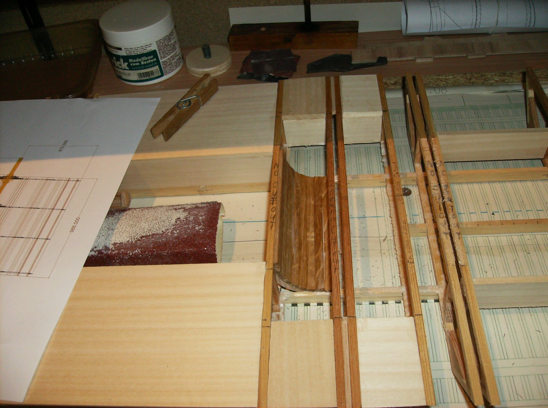
Last days were busy for family things, but a bit has gone on too. First I had to play the @dafi and break out the former glued in floor in the engine room, and replace it with the curved part to the paddlewheel.
The former version with the floor

The new curved parts, all unnecessary beams will be cut away after planking the hull!
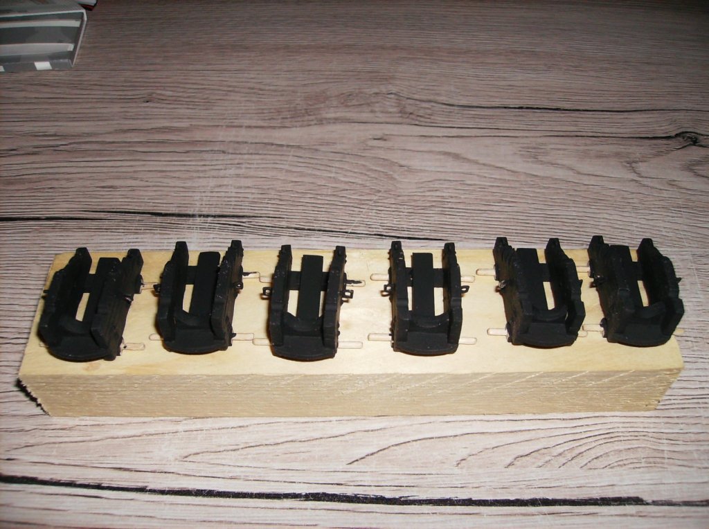
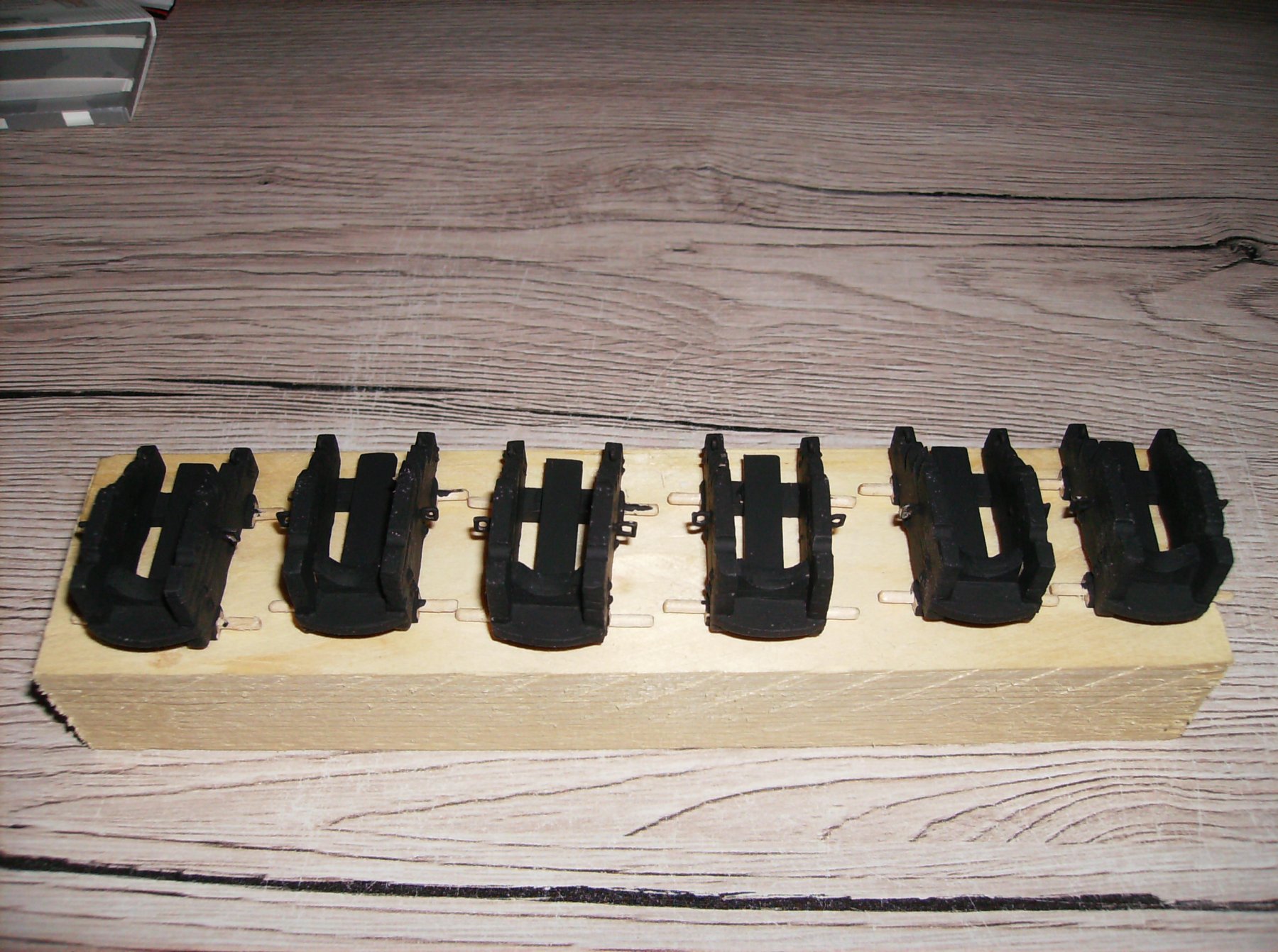
Next was the larger carriages I made "far ago". They were painted flat black. I have read the johnhoward file, but decided to let it with only two different carriages for the great guns.
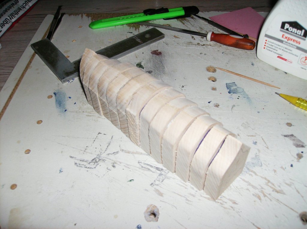
And then there was the core for the cutters. This is hard work, grinding it by hand, but the shape comes out slowly !
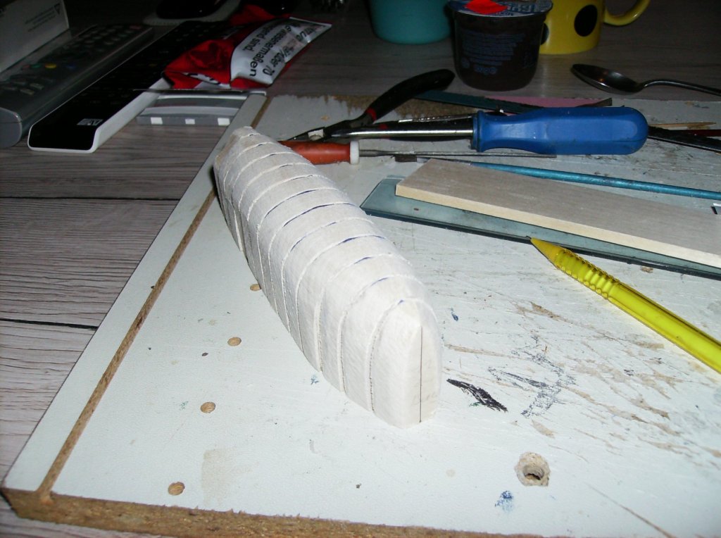
Best regards, thank you all for watching!
Gerhard
-
6 hours ago, cog said:
You are creating some fine details, Gerhard. Will you paint the insides flat black too?
Hi Carl
Thank you! And many thanks to all interested for watching in & likes!
The insides will be whitewashed, as all inside walls will. Engines and boiler parts will be blackened, as the original parts were. I HOPE, I can make the boilers as the 5 tube boiler that was there, but must calculate how much water volume they will have, and build a feeding pump to them for longer driving!
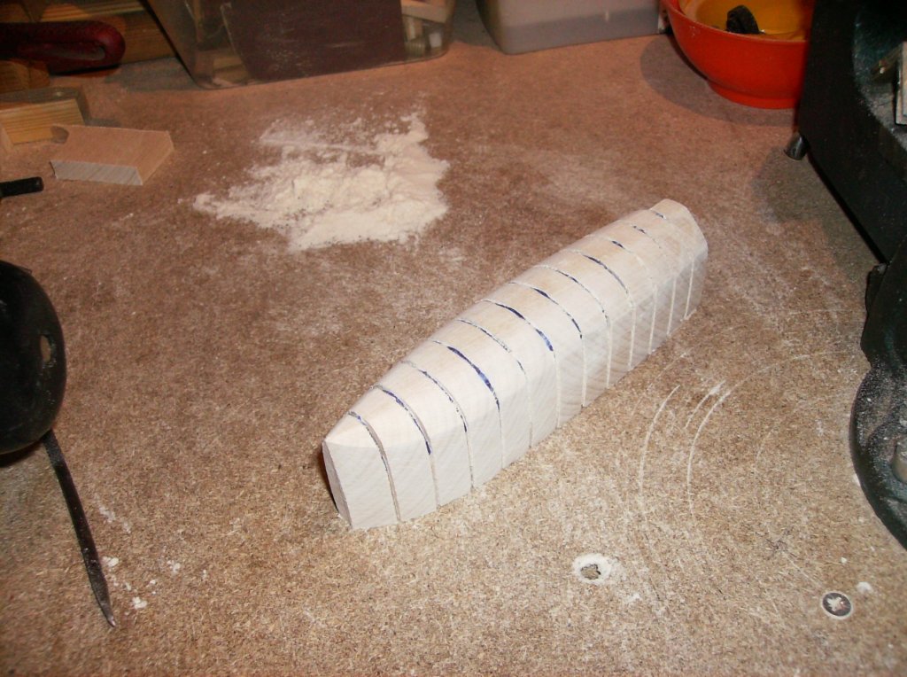
Still grinding the core for the cutters at the time, no grinding machine in my shop, so I have to do it all by hands only!
Regards
Gerhard
-
Hi Nils
The DX Fix is a bit to strong for that small boats, in my mind! I would try it with the method from Nenad/Greg, think this would be much better than the foil. Or instead of that really thin shirt fabric (Hemdenstoff), strenghtened with thinned glue.
Regards
Gerhard
- mtaylor, Piet and Mirabell61
-
3
-
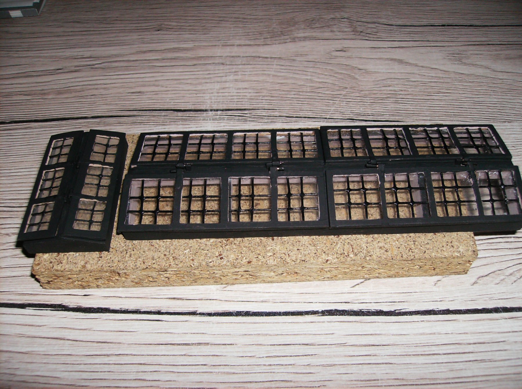
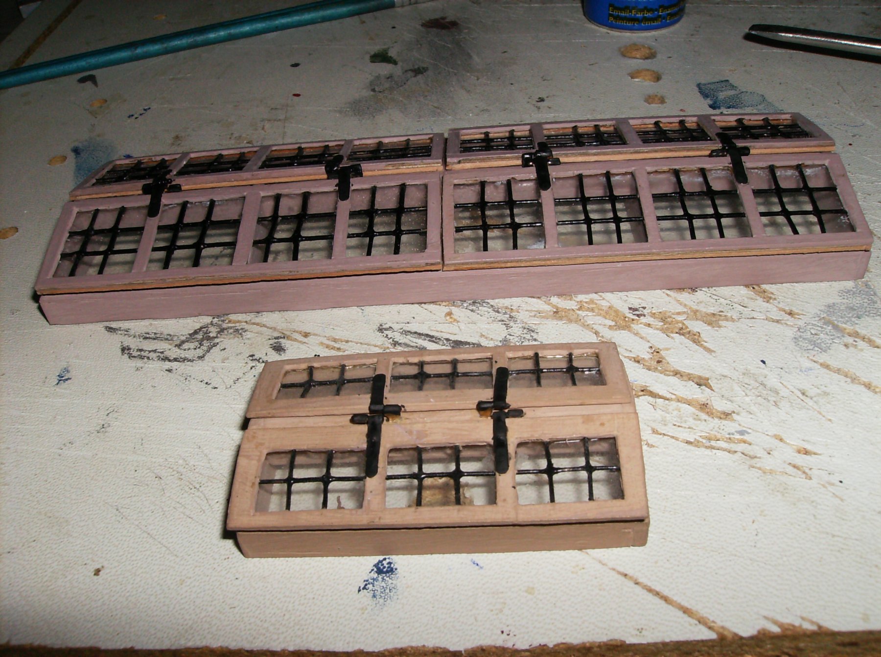
Worked a bit on the core for the cutters, and painted the skylights with flat black. Looks a bit better than the brown colour, thanks for giving some advise go to @johnhoward

Regards, Thank you all for watching!
Gerhard
-
Hi johnhoward
I found one phpto at the NPS Site, and searched then for the Southern Belle stove. Was pretty easy to find, and looks like the original thing. Most important is the location for the vent, which is clear now, thank you! Those infos are worthful for anyone who likes to build a City Class ship!
Regards
Gerhard
- Canute and johnhoward
-
2
-
Johnhoward
I think I have some of those candles somwhere in my storages, must search for them. But they are not expensive, if I dont find them I`ll order some
")
Good hint, Thank you!
Regards
Gerhard
- johnhoward, Canute, mtaylor and 1 other
-
4
-
36 minutes ago, johnhoward said:
Gerhard,
Your decisions on the glass and hinges sound reasonable.
I would make the whole exterior of the USS Cairo flat black or dark gray to minimize visibility on the rivers at night. You wouldn't want any bright contrasting trim which would attract attention. However, I think the interior surfaces should lighter gray or even "whitewash" to retain reflected light thereby providing the crew with maximum visibility in the dark spaces which were only lit with flickering candles or kerosene lamps.
This is the general color scheme we are using for our USS St. Louis. Blackout of interior lighting while on patrol would also be strictly enforced. These ironclads were always dangerously close to the river banks and enemy snipers or more powerful weapons.
johnhoward
Hi johnhoward
Thank you, so I will change colour to flat black for the skylights, no big deal to make it. The ship will get LED lights in it, so all visible interior will be seen well, but I will have to search for flickering lights to get a real effect. The inside of the superstructure will be painted light grey or dark white, the way you mentioned as "whitewashed".
Regards
Gerhard
- Cathead, Canute, johnhoward and 1 other
-
4
-
Hi johnhoward
I will stay with hinges, too much work to break them out of the frames. Breaking out the "glass" would be easier, but as I will let the windows open for sailing, this will not be necessary. I need good ventilation for the boilers and engine as this ship will get life steam, and I like to close such skylights when the model is set in the showcase. Much interesting is the question for coluor of the skylights, I found nothing about that! Shall I keep them as they are, or would (flat) black be correct?
Regards, and thank you all for watching
Gerhard
- mtaylor, johnhoward, Canute and 1 other
-
4
-
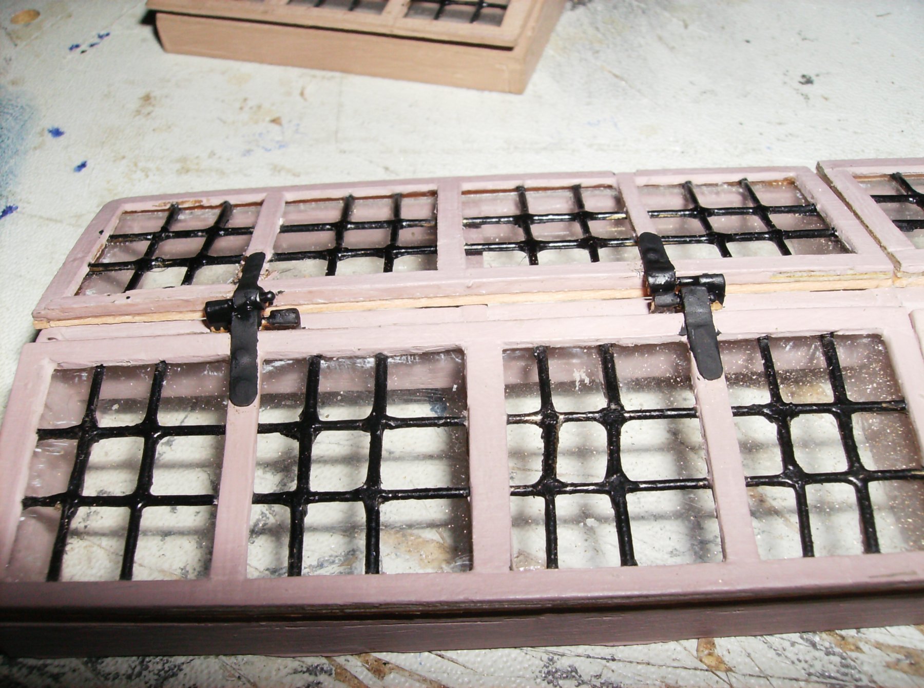
Hello again, and so many thanks for your likes!
Before I continued with the cutters core, I had to finish another work I`ve started earlier. The big skylight had no window glasses and no hinges, so I decided to make them first. If the coluor would not be correct, please dont be shy and give some info about the paint of this parts!


After the skylight I made the core for the cutters, must be grinded to shape now. Then I can start with the frames and planking.
Regards
Gerhard
-
Hi Johnhoward
And....................
Where was this located??
I`m ordering all the wood material for the Cairo this upcoming week, so this would be good to know before I continue, dont want to go wrong

By talking about the stove, found some pics from the Southern Belle stove
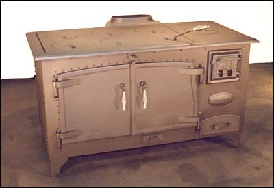
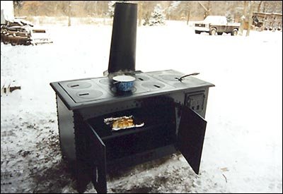
Best Regards
Gerhard
-
7 hours ago, johnhoward said:
Gerhard, Antony,
Thanks for your nice comments. The participants in the photo, left to right, are: Fred Hecker, Tim Jovick, Tom Stahl, Vince Murphy, Howie Smith, Bob Keeler, Dr. Mike Orgel, & Bill Kammermeyer, [Scott Safranski was missing]
Gerhard, I'm not sure I totally understand your question on the City Class funnels but I've attached my reconstruction of the corrected propulsion system schematic (versus Ashley's NPS version) showing the engine steam exhaust entering the boiler water pre-heaters and exiting thru a 2-way valve either aft into the wheelhouse to prevent paddlewheel icing in the Winter or forward thru the firebox exhaust plenum into the 2 main smoke stacks, not a separate exhaust stack. I think I have also correctly depicted the "Doctor"engine operation and its piping connections in this schematic.
By the way, Bob is working on a TurboCad drawing to construct our brass 12-pdr lightweight carriage by re-scaling some un-dimensioned drawings we have, based solely on the known howitzer barrel length dimension. I noticed a nice drawing in the background of your recent carriage model photo and wonder if it has any other actual usable carriage dimensions.
johnhoward
Hi johnhoward
Thanks for "lining up" the participants of the project!
You did understand the request for the steam exhaust system correct. So I dont have to worry about the stacks for the engine, and build some tubes from the engine via the preheater back to the big funnels from the boilers. Paddlewheel icing will be no problem here in Vienna
, but the water preheating system will be made.
The drawing for the 12-pdr came from the civilwar-website, I scaled it down to the correct size of the barrel and made the carriage from the scaled drawings. Would be interesting if my scaled drawing will fit to Bob`s TurboCad drawings!
Best regards
Gerhard


USS CAIRO by Gerhardvienna - RADIO - live steam
in - Build logs for subjects built 1851 - 1900
Posted
Hi Pat
Thank you for your nice comment!
A bit more to enjoy.....
The floor to the engine room is set in again, now from 1mm plywood. This is just thefirst layer of the floor, another layer from 2mm plywood will follow with the engine. And the engine stands are in progress, while I`m still waiting for much more wood and other materials for the Cairo.
The floor in the engine room
Beginning of the engine stands. The gaps between the timbers will be filled with small pieces from wood, so the stands will hopefully look like the original ones.
Regards, and many thanks for watching & nice likes
Gerhard