


Gerhardvienna
-
Posts
683 -
Joined
-
Last visited
Content Type
Profiles
Forums
Gallery
Events
Posts posted by Gerhardvienna
-
-
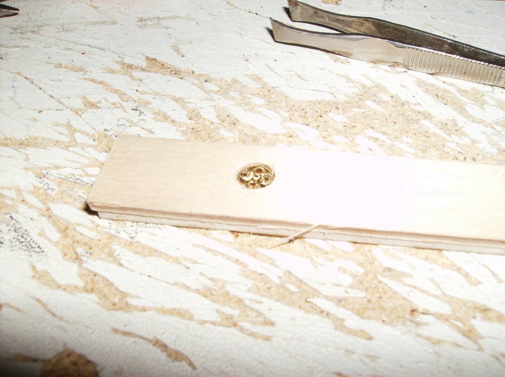
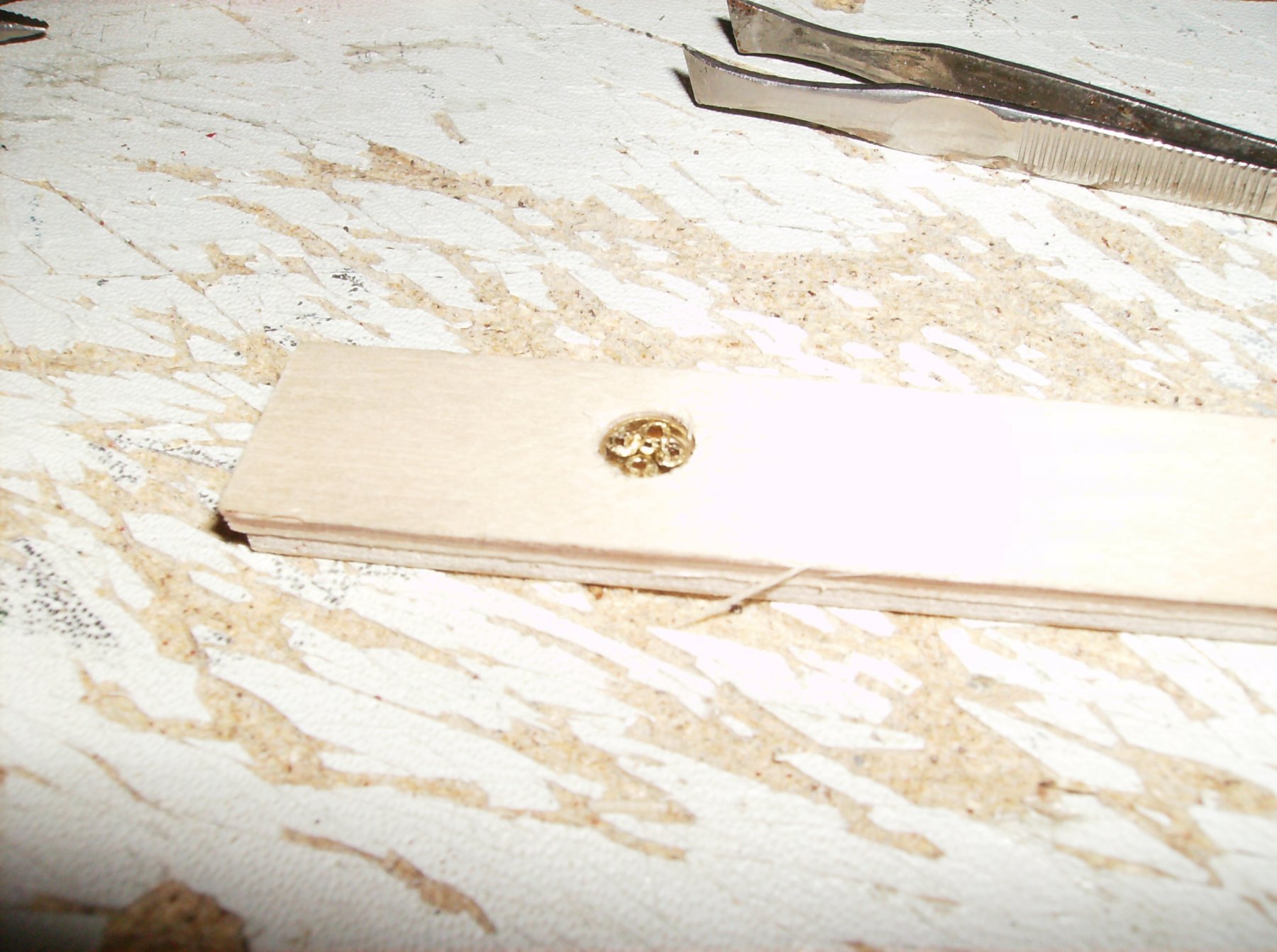
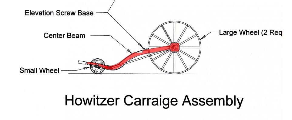
Back to the 12pounder carriage, I made the small rear wheel. I used 6 mm brass tube for the "tyre", 4 pieces of 2mm brass tube for the rim, and 1 piece of 1mm brass tube for the hub. I had no 1,5mm tube, so i had to use the 2mm, and could set only 4 instead of 5 pieces for the rim, but it looks good, I`ll keep it.
All the little pieces in the soldering form
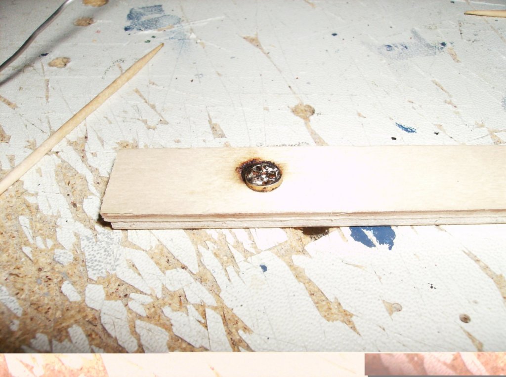
After soldering.....
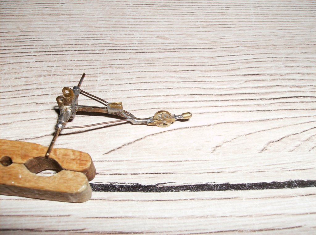
Filed to correct width, and mounted to the carriage
Best regards, thank you all for watching, thanks for comments, hitting the button,
Have a nice day!
Gerhard
- mtaylor, hexnut, popeye the sailor and 7 others
-
 10
10
-
-
-
8 hours ago, jablackwell said:
Hi Per,
. I am intrigued that there are two of us here now working on planes...
~john
Hi John
You two are not the only ones working (or planning) on planes.............
I have collected good drawings for more than 200(!) aeroplanes from pre WW1 to modern, just thinking which one i should do

Great job done on your Fokker!
Regards
Gerhard
- thibaultron, Nirvana, jablackwell and 3 others
-
6
-
Hi johnhoward
Thank you and Cher for that, once more some new views from the engines. Especially the first three pics show the engines from another angle, I`ve never seen in any forum or website! There will be some differencies in my build, due to the conditions for sailing the ship by RC. But most of the components of the engines will be really close to the original one!
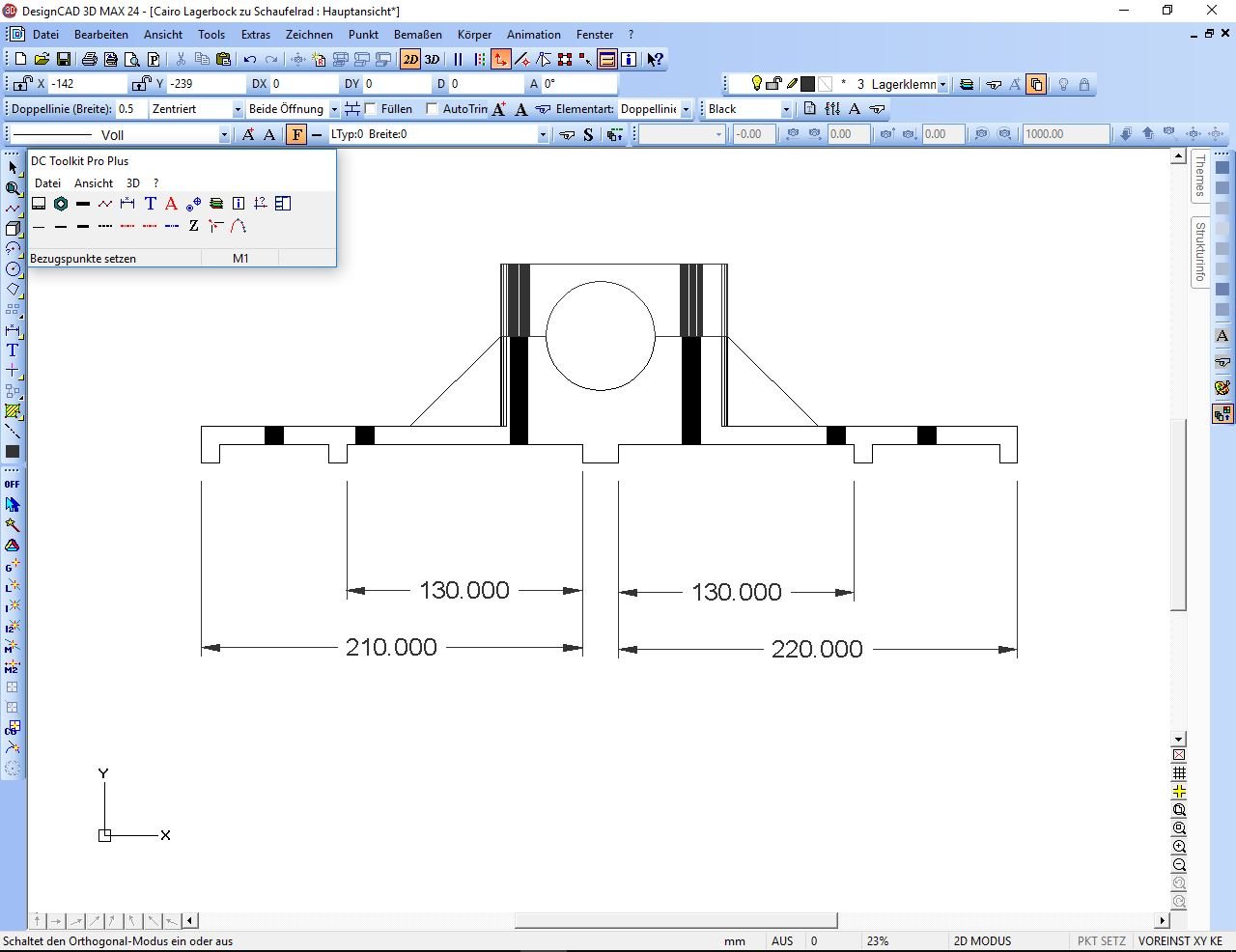
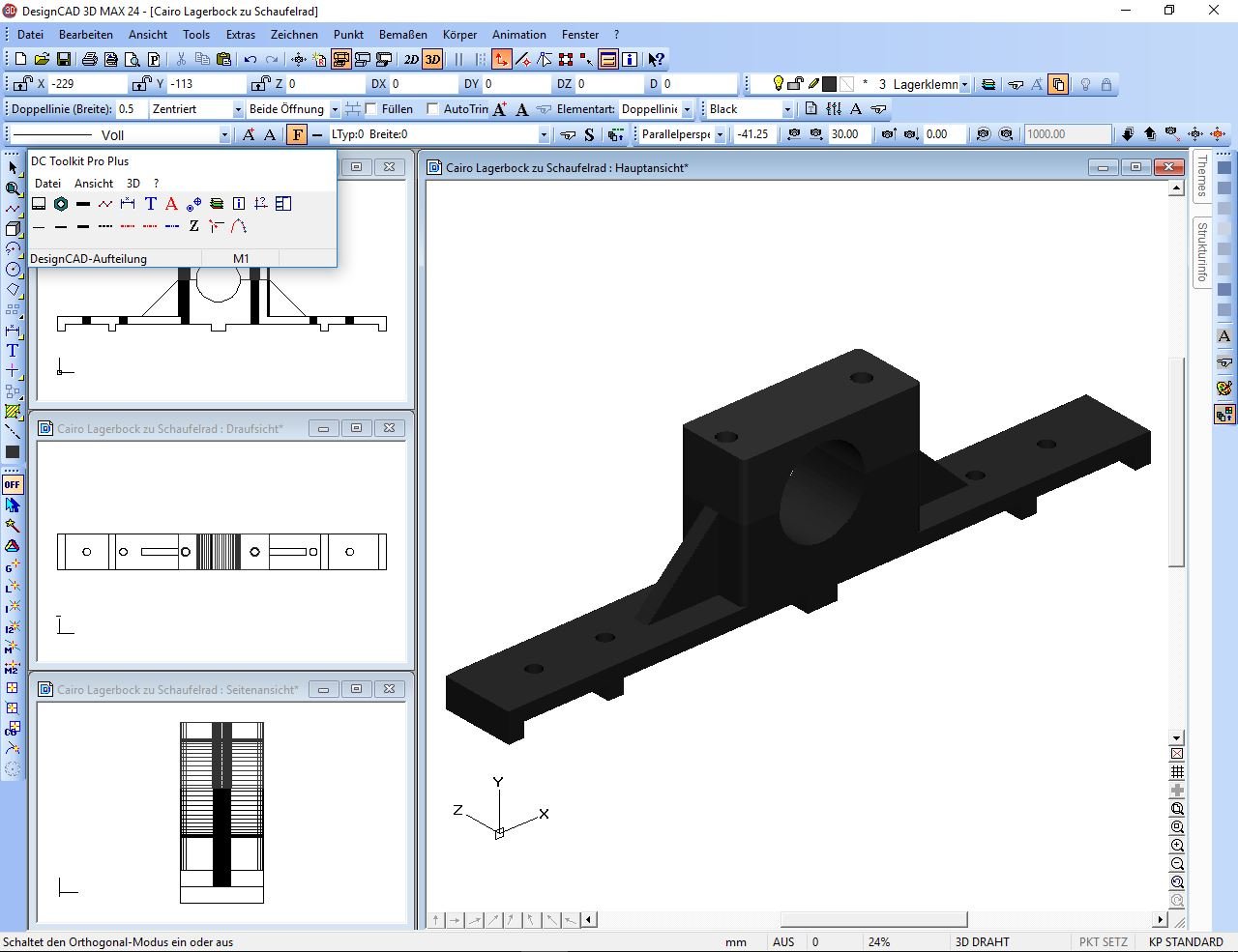
Meanwhile I made the drawings and .stl files for the paddlewheel bearing blocks, they will be 3D printed. This saves a lot of working time, and makes it easier to work with.
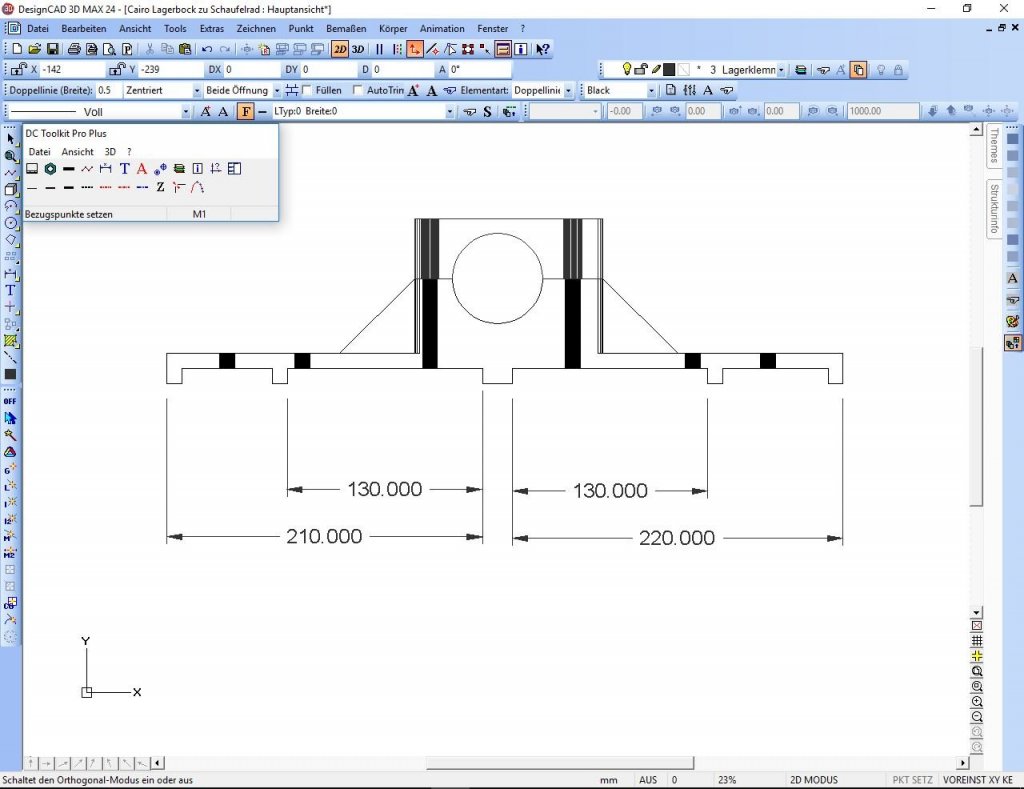
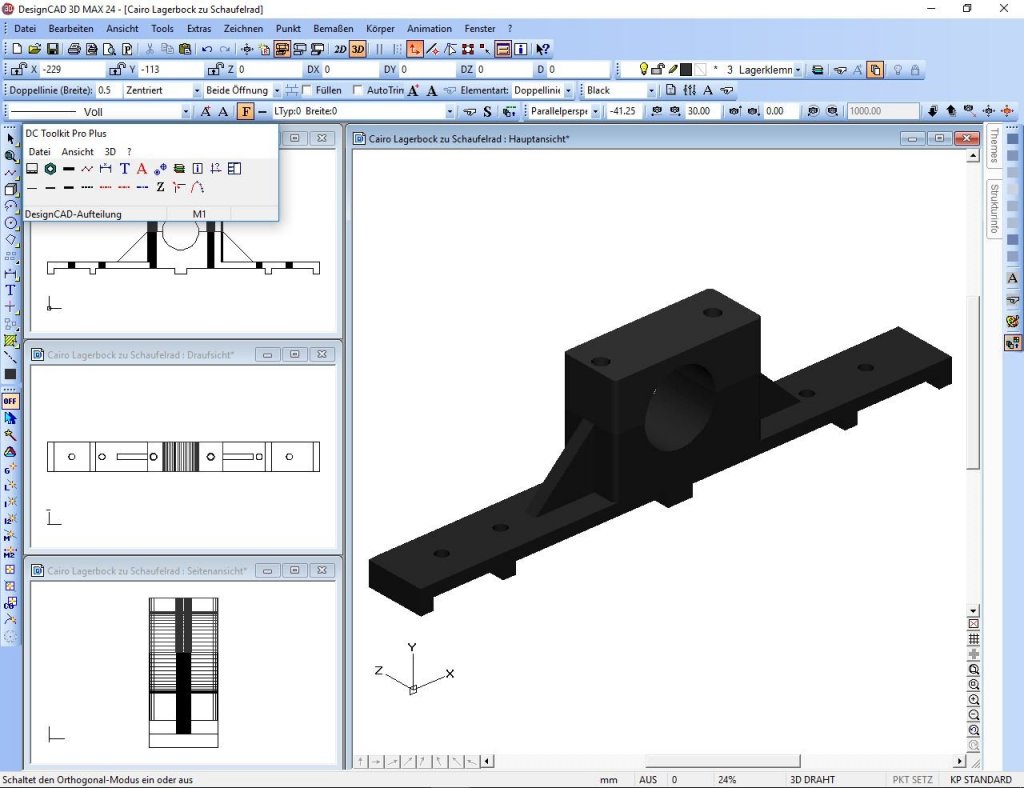
All measurings on the drawings are in 1/10th mm!
Regarsd; and thank you all for watching!
Gerhard
-
2 hours ago, johnhoward said:
................striving to achieve the highest degree of accuracy possible in your model.
johnhoward
Isnt that why we are doing what we are doing?
If it were a fantasy build, nobody would care, but as we try to do "dowsized copies", they must be accurate. Just my two cents...............
Regards
Gerhard
- Cathead, mtaylor, johnhoward and 1 other
-
4
-
Hi johnhoward
So they were meant as ventilation funnels, i got it now
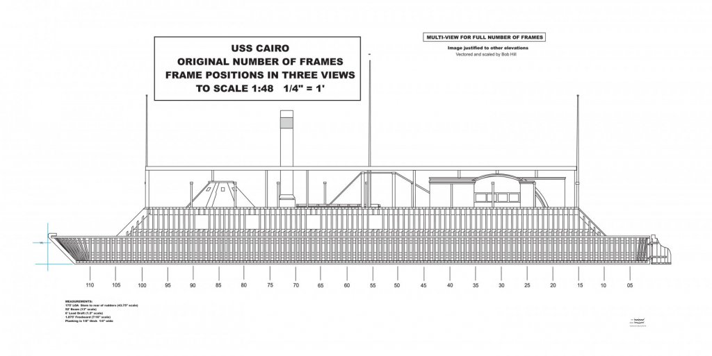
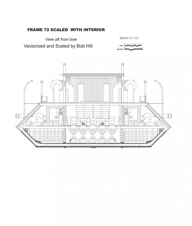
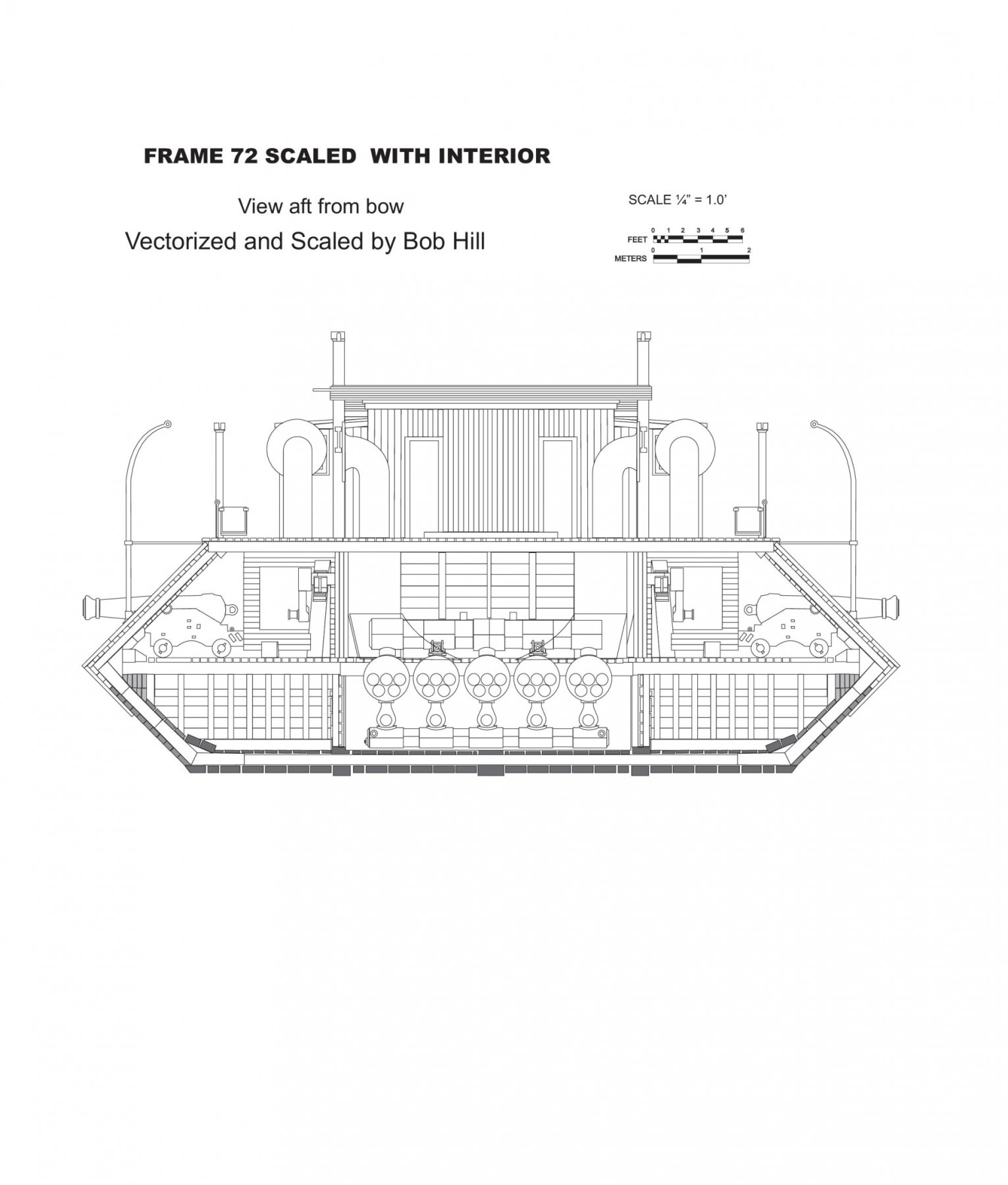
 ! The position of them should be good to see in the Bob Hill plans, but there is a difference for the ventilation grate. In his side view frames plan the grate seems to be roof shaped, as I made it, in his plansheet "Frame 72 with interior" he shows the same part flat as you made it. I can still make that change, would be no problem, but I must be sure to make the correct decision!
Regards
Gerhard
- johnhoward, Canute, Cathead and 2 others
-
5
-
3 hours ago, johnhoward said:
Gerhard,
The four ventilation funnels only extended thru the hurricane deck and not thru the gun deck. After the Civil War some of the surviving ironclads such as the USS Cincinnati were modified to add openings in the aft side casements, which would have been extremely hot without any gun ports, as seen in some contemporary photographs. The USS Cincinnati had been sunk twice and recovered, which probably explains these modifications.
Have you discovered any others?
johnhoward
Hi johnhoward
Maybe I`ve dicovered some, in Wikipedia I found a pic from the Uss Cincinnati, with openings under the aft boat, and somewhat like a small trunk on the rear superstructure. Maybe this was a later modification?
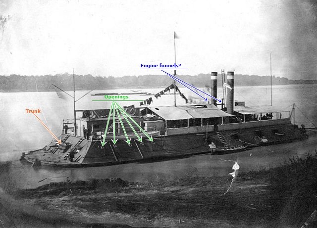
Pic source : https://en.wikipedia.org/wiki/USS_Cincinnati_(1861)
On this photo I also discovered two narrow tubes(?) behind the big smokestacks, could this have been funnels from the engine? and; where were the four ventilation funnels located?
Questions, Questions, Questions.....
Best Regards
Gerhard
- johnhoward and Canute
-
2
-
Hi Patrick
That is the bad influence that drags us to new skills

Regards
Gerhard
-
-
-
-
-
Hi johnhoward
Great progress! And nice work on the wheels too!
Regards
Gerhard
- Canute and johnhoward
-
2
-
-
Hi johnhoward
Thank you, great pics, and many thanks to Cher too. NOW i know, why I`m a Cher-Fan

For smoe reasons I found no time to compare my version of the light carriage with your drawings, these photos show a lot more than I had before from the original thing!
Best regards
Gerhard
- Cathead, mtaylor, johnhoward and 1 other
-
4
-
I addition to the "engine discussion" I finally found the site I was lokking for:
http://thevintageaviator.co.nz/projects/oberursel-engine/oberursel-ur-ii-rotary-engine-build-history
Regards
Gerhard
- Torbogdan, popeye the sailor, Canute and 1 other
-
4
-
5 hours ago, BANYAN said:
............. - it took me 14 years to complete my first model
") Life simply gets in the way sometimes.
Life simply gets in the way sometimes.
cheers
Pat
Thank you Pat!
So I`ve got 13 years more for the Cairo
, but i hope it will not take that long. No clue what I will do next, today I must visit my parents-in -law, maybe there is little time later for the ship.
Regards
Gerhard
- mtaylor, Canute, popeye the sailor and 1 other
-
4
-
16 minutes ago, cog said:
Following and watching in amsement ... can't seem to get updates often enough, Gerhard.You need to speed up things
")
Hi Carl
I KNOW, I should have to speed up................
But there is so much to do exept model building, but with time there will be a new born Cairo
Best Regards
Gerhard
- Canute, cog, popeye the sailor and 1 other
-
4
-
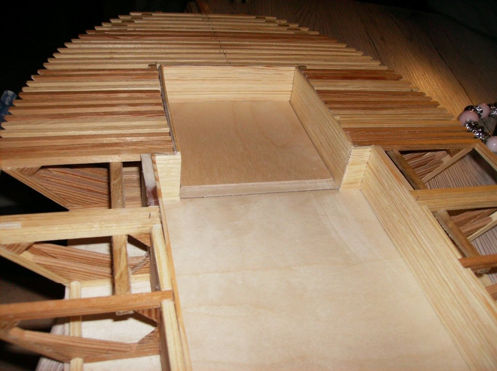
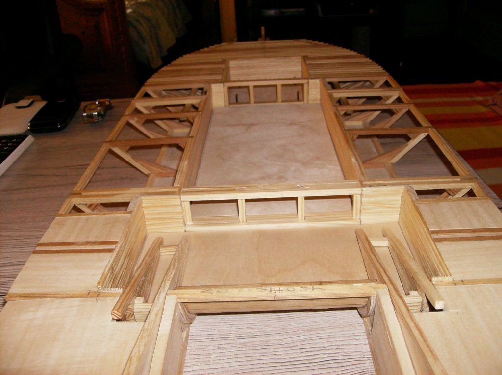
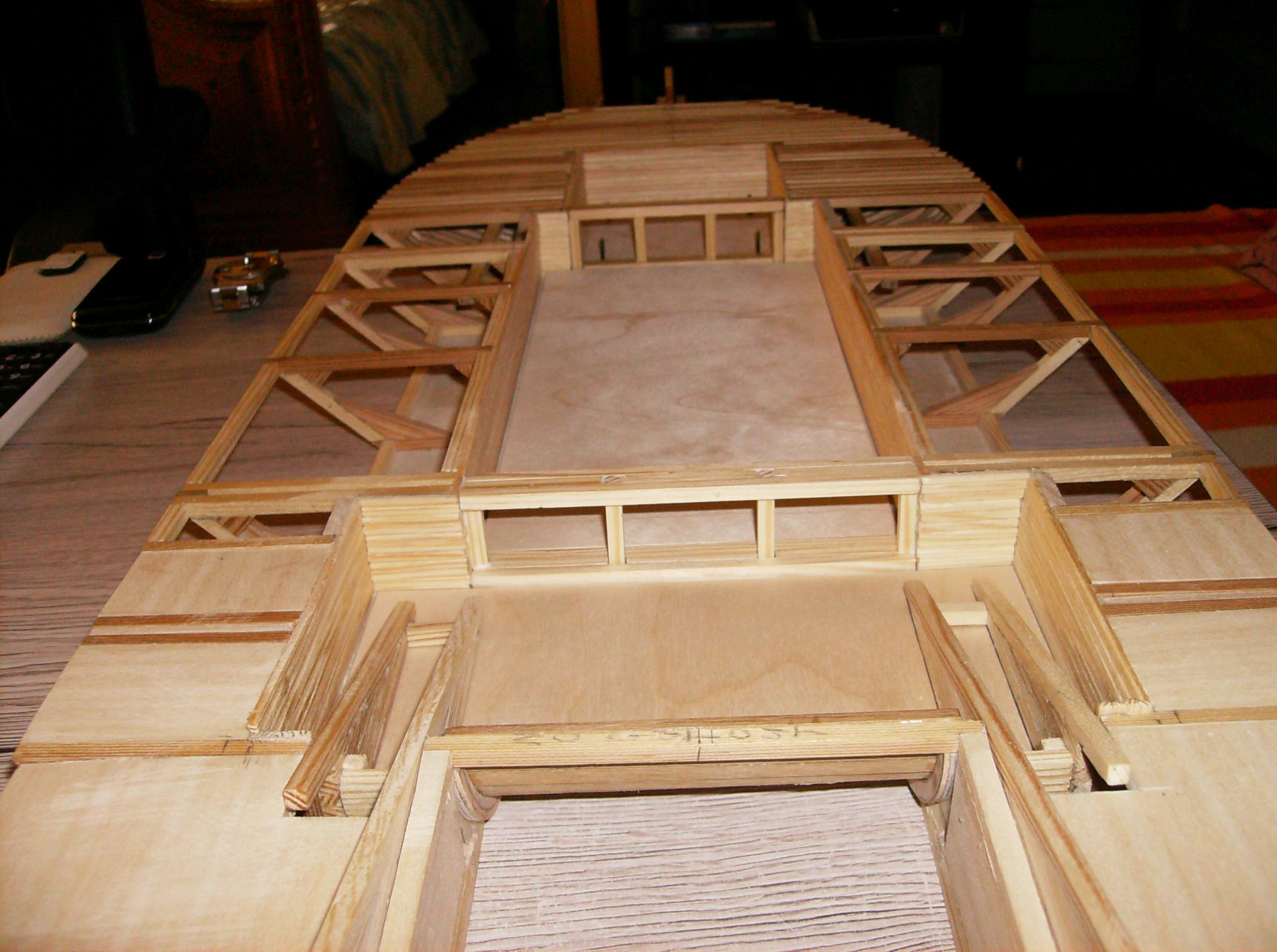
Has been some days till my last report, heer comes the news. I could set some timbers to the inner structure, just to make the walls look a bit better than they were from plywood. Cut a lot of 2 x 3 mm pinewood strips, and glued them to the walls. And I made 2 crossways from port to starboard, there I used 5 x 5 mm pine wood.
Timbers glued into the gas tank room
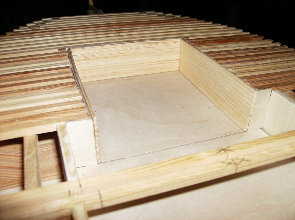
All internal walls related to the engine compartement are glued in, all unnecessary frame parts are cut away.
The crossways from port to starboard side
Thank you for watching, and comments or critics too!
Regards
Gerhard
-
-
Hi Nils
Now she comes alive, so well done so far!
Regards
Gerhard
- Mirabell61, Omega1234, cog and 4 others
-
7
-
7 hours ago, popeye the sailor said:
thanks Gerhard......but Gibbs is a dog
I've run into another uh-oh moment.......with the bow spirit in place, the fore mast won't fit into it's lower hole. bother!....I was afraid of that 
.......now I'll have to get a saw
since this is an ocean going vessel....should I use a sea saw?
Sorry, did not want to offend the DOG!!!
Why dont you file a bit away from the lower end of the mast to fit it into the hole? If its only the lower hole, noone will see it after.
Regards
Gerhard
-
Hi Denis
Nice repair on that cat eaten shroud! And nice progress too!
Regards
Gerhard
PS.: Me and you seem to have the same admiral................................
- popeye the sailor, Piet, EJ_L and 1 other
-
4


USS CAIRO by Gerhardvienna - RADIO - live steam
in - Build logs for subjects built 1851 - 1900
Posted
Hi Carl
Thank you! Took me more than one attempt to make it, the first tries were absolutley bad. Did not photograph them, but in the end it worked out fine.
Regards
Gerhard