Ian_Grant
-
Posts
2,156 -
Joined
-
Last visited
Content Type
Profiles
Forums
Gallery
Events
Everything posted by Ian_Grant
-
 A lot of us have followed Glen through many of his superb SIB builds. This is a nice change...
- 301 replies
-
- 7
-

-

-
- Constitution
- Bluejacket Shipcrafters
- (and 1 more)
-
Love how your cat just had to work his/her way into your picture.............😉 Ours is like that too.
-
I forgot to include a shot of the remaining removable deck glued to frame and weighted down, with what I had available.
-
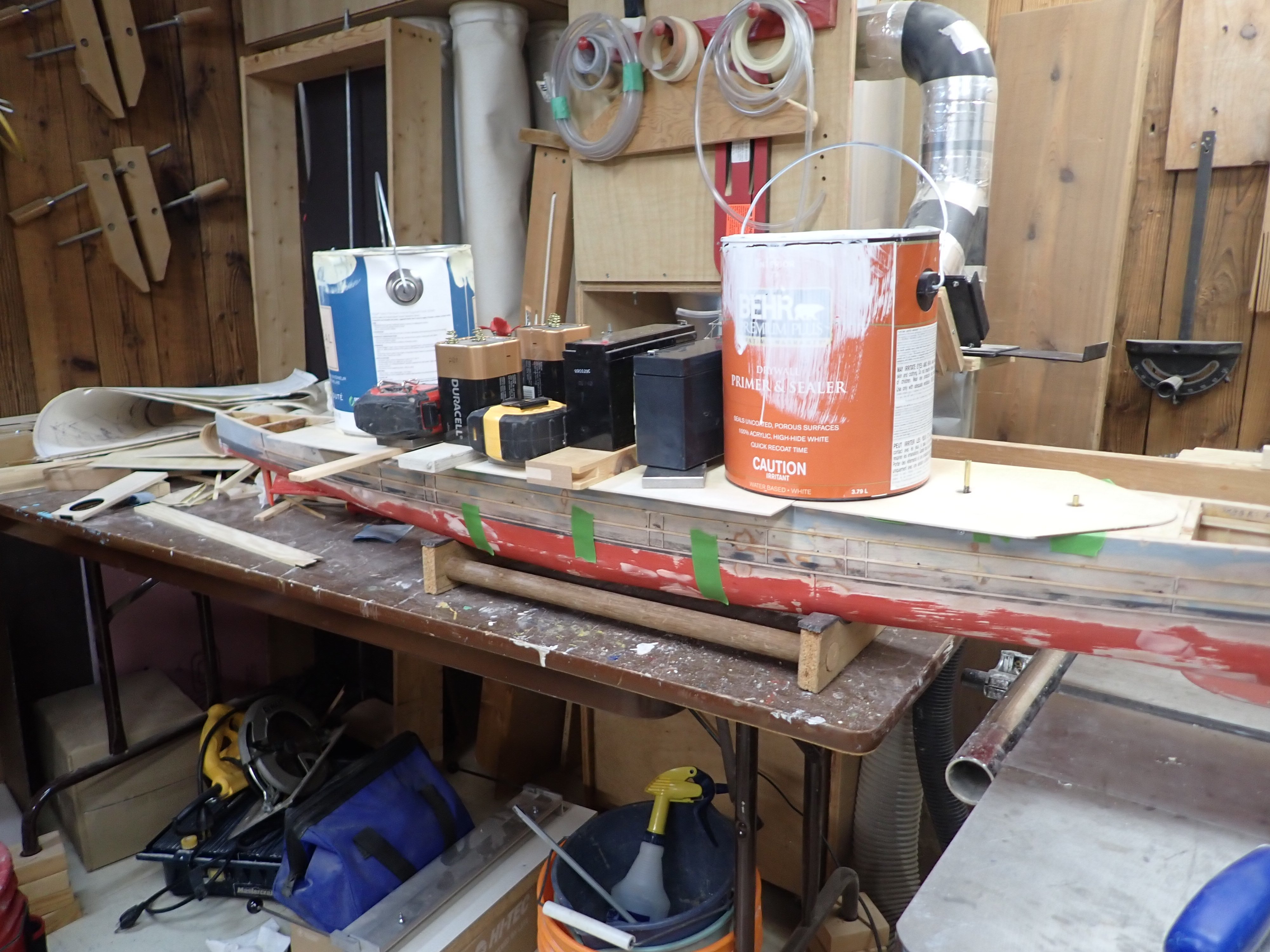
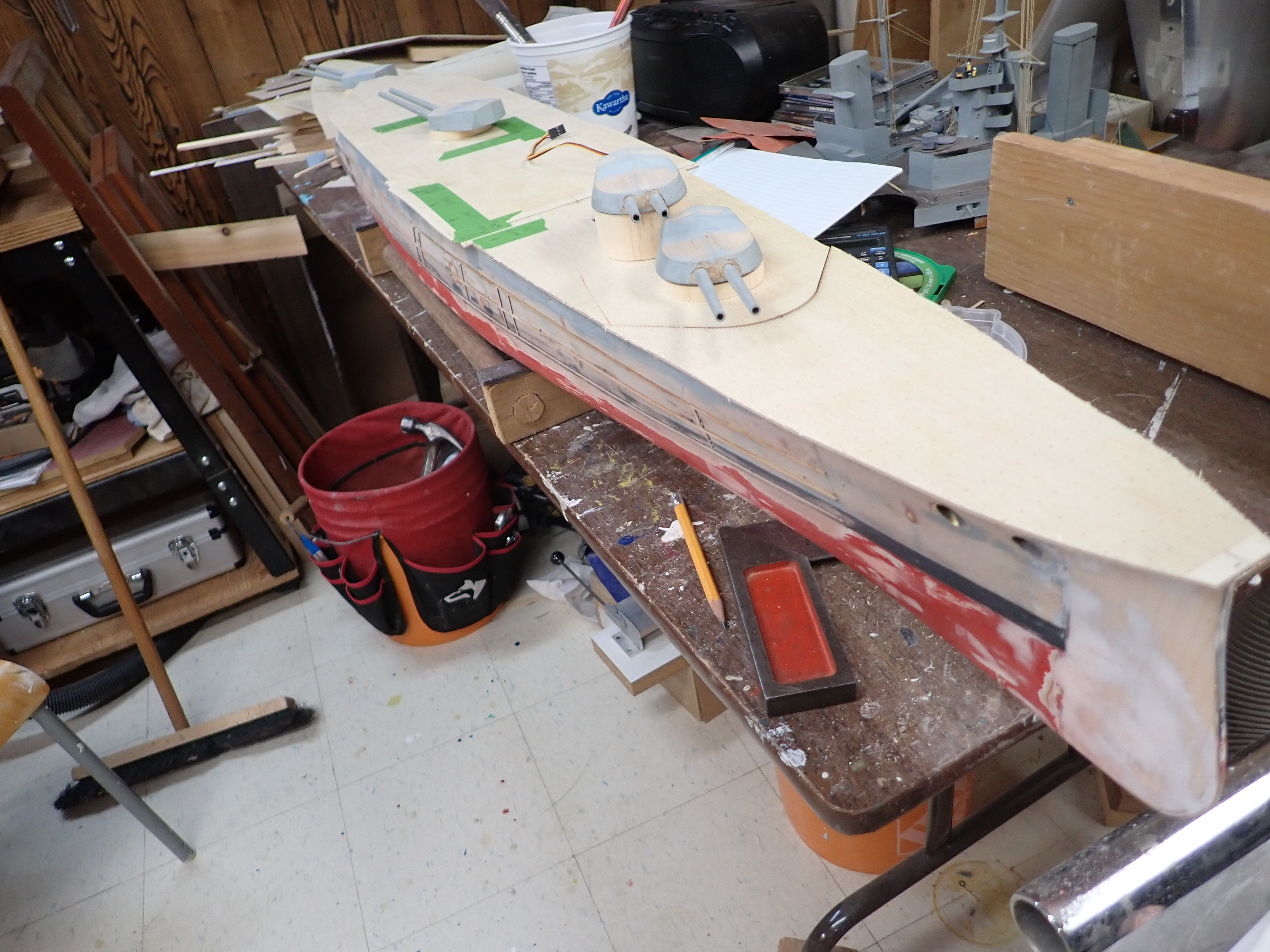
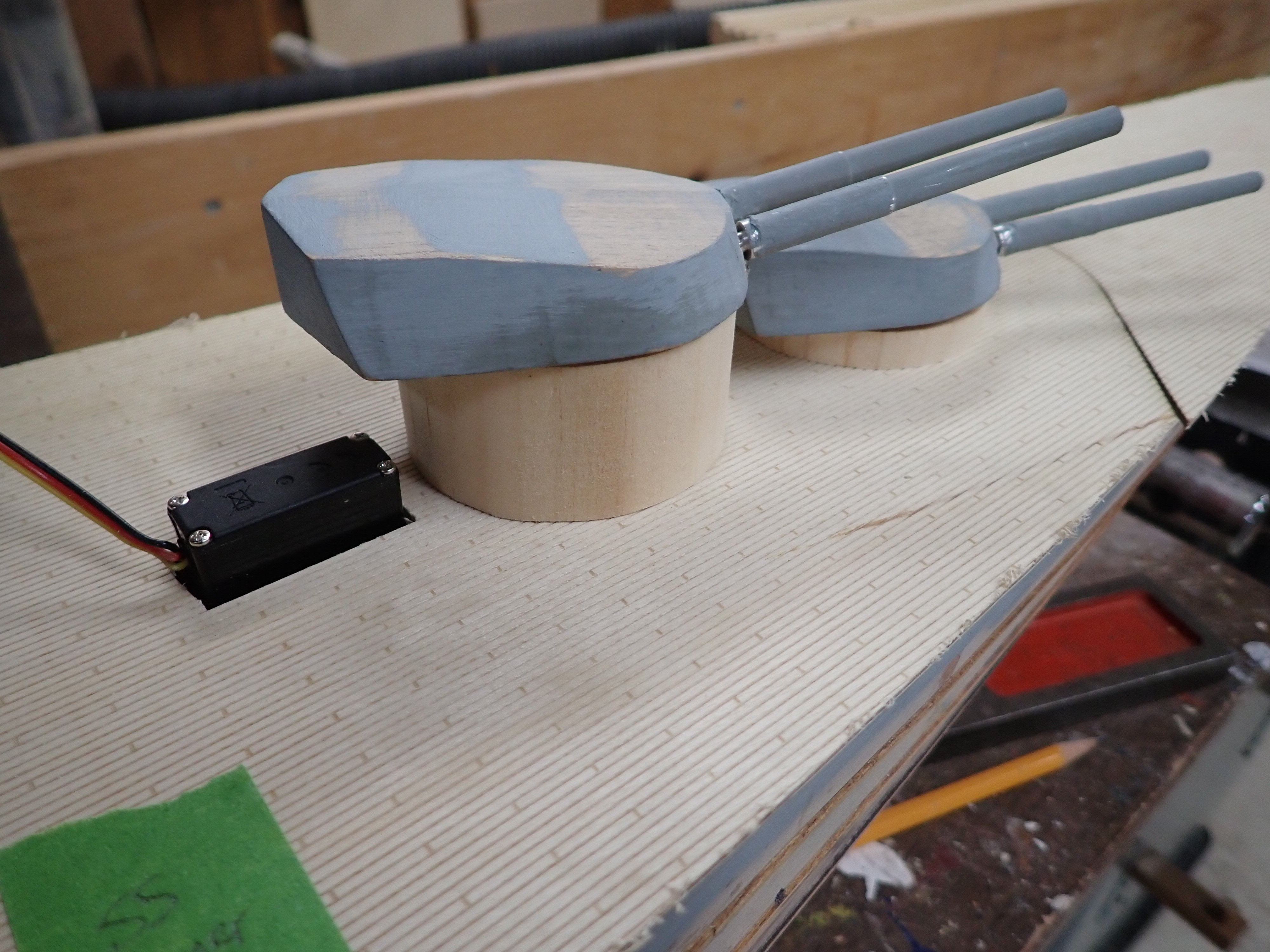
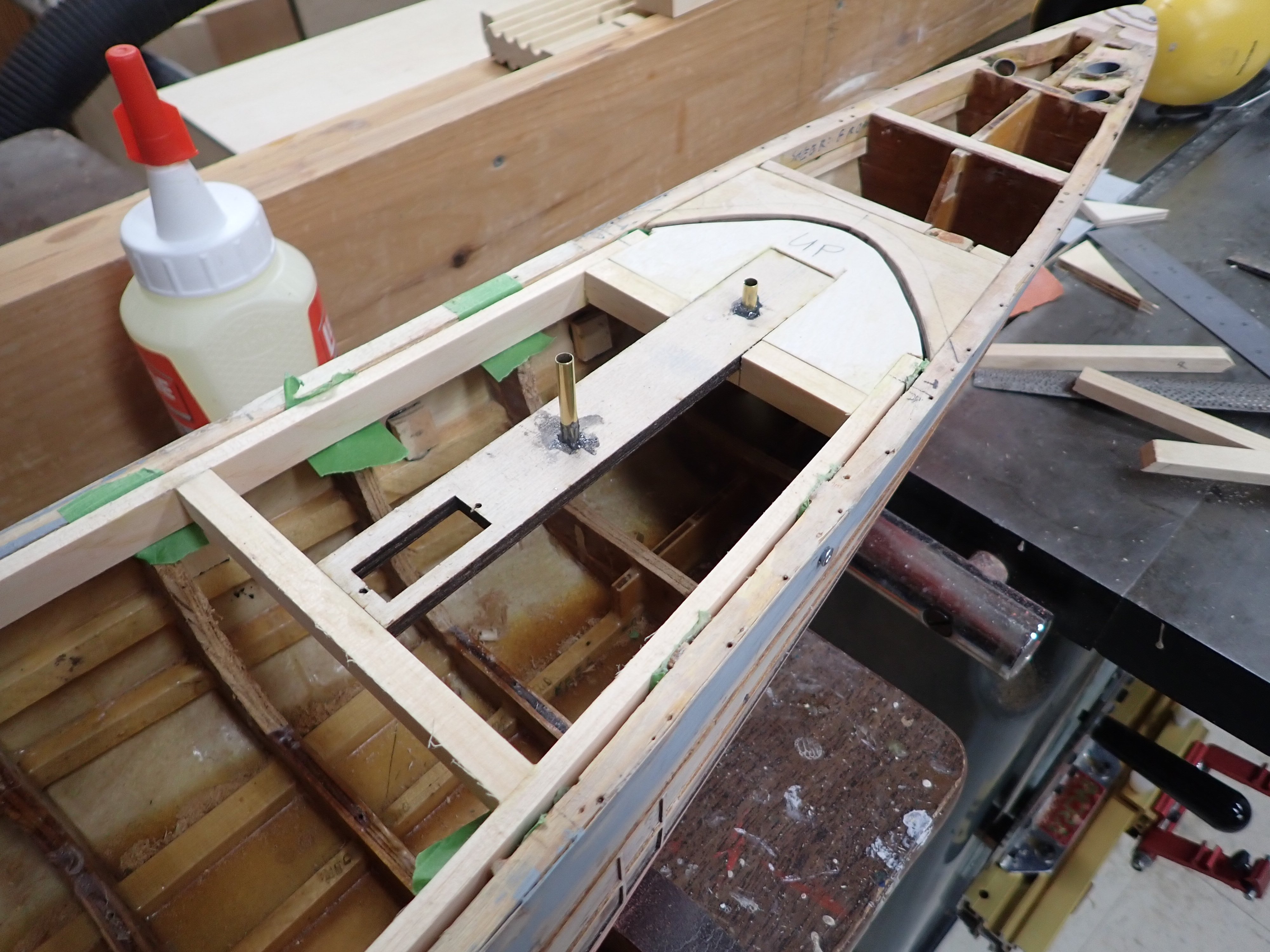
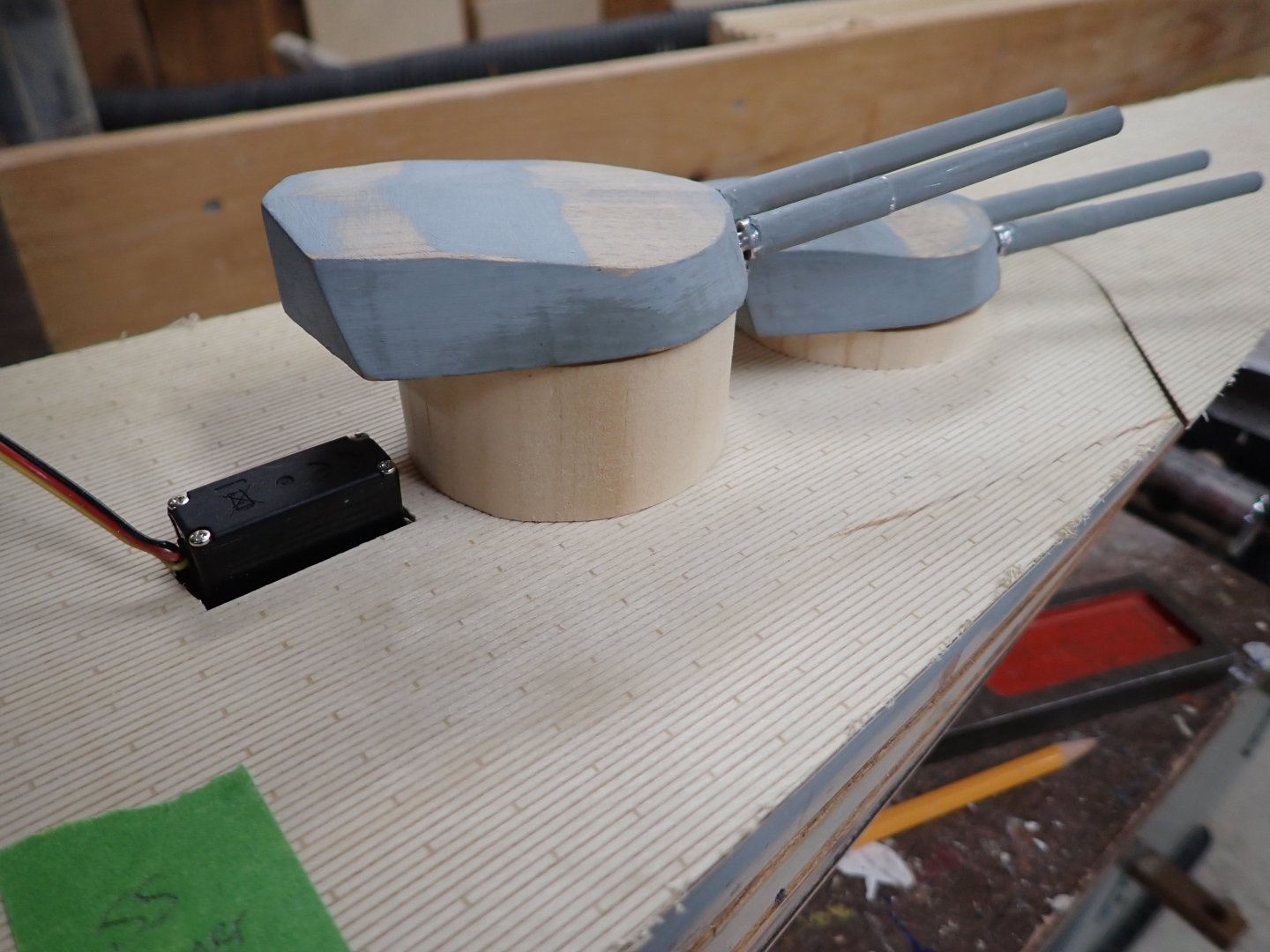
Decks bandsawn (bandsawed?) roughly to shape. Decks have a "shelf" projecting slightly beyond hull side for most of the length; this was used to store the brailed-up torpedo net. God knows how I am going to make the "brailing davits" which occur about every 2" along the rails. I made a start at marking out superstructure locations in green masking tape. Foredeck and aft deck not glued down for reason given above. Some turret barbettes were made from some old pine I had lying around, by gluing up a rectangular blank, centre-drilling along the axis, then sitting the blank on a rod inserted into scrap plywood and rotating the blank into my tablesaw blade. They're good but not perfect; I had planned to 3D print them in PETG and will probably do so anyway. Micro servo which rotates the forward turrets sticks up through the deck behind "B" turret; it will be hidden in the forward superstructure below the shelter deck. I'll need another big hole under there for the sound effects speaker to emit into air without being muffled by the hull. Luckily the fwd shelter deck is open along the aft edge. I've realized that dad machined the front lower corners of the turrets a bit too low. Am considering adding shims tapering from 1/16" to zero at centre of each turret. Also need to 3D print some rangefinder and sighting hoods. Thanks for following. Ian Too bad about the plywood flaw to starboard of the turrets. Oh well.....😞

-
I've said this before, but you've outdone yourself yet again, Glen! Love the chain and rusty nameplate; they go perfectly with the ambience of the tattered sails. Waiting to see what you come up with next! Regards, Ian
- 185 replies
-
- 7
-
-
-
- Flying Dutchman
- Black pearl
- (and 2 more)
-
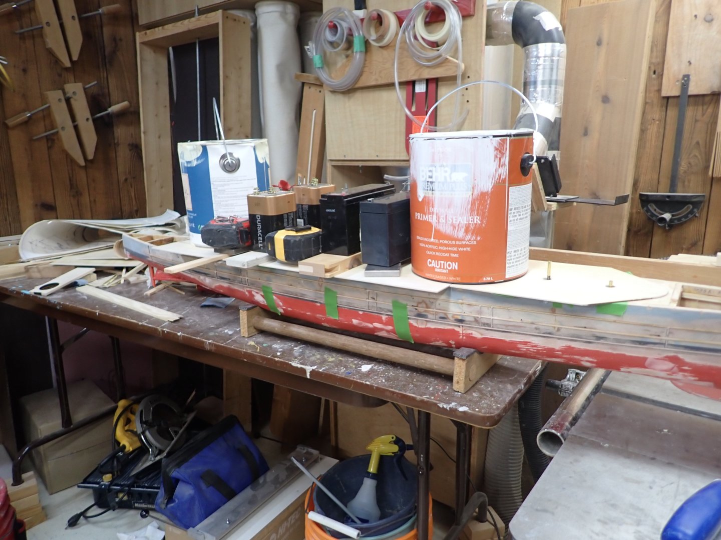
First piece of deck glued down to the removable frame, and hopefully not to the nearby hull frames. This deck runs aft from the breakwater to beneath the forward superstructure where it is full width, to hide the seam. The next piece will run the remaining length of the removable portion. Here it is weighted down while glue sets; sadly I lack sections of railway track. I'm considering bringing in some of my extra bricks from the garage when the next, longer, section of deck goes on. I can't glue down the forward and aft fixed decks until I do a float test and decide how much unaccessible ballast to add - I'm shifting the main battery forward one compartment compared to the original location to allow the smoke unit to take its place between the fwd and aft stacks. (Assuming I can fit in the unit and its piping). I expect less ballast to be required at the bow.
-
Hmmm.... I've been wondering about ladders! Teenaged me used some brass coarse representations of ladders I found somewhere. Probably will need more to meet increased accuracy requirements. I see a 0.2mm nozzle in my future......
-
Nice Victory lanterns, Kevin! I bought the Bambu A1 instead, in the end. We were away and then Christmas loomed; I haven't done a damn thing with it other than printing a "boatie" which my daughter immediately claimed. Last thing I recall I was having trouble getting my PC to "see" the printer through our WiFi. Will need to look into it as I'm getting close to needing some 3D printed superstructure parts.
-
Yeah, and slipping while using a bandsaw makes a mess too, which I discovered last year on another build. 'Nuff said. 😭 I woke up with the idea of temporarily fixing the ends of the taper at where the wood wants to be naturally and simply belt sanding the high side and the plywood gusset until level, instead of messing up the angles which were a pain to achieve. Think I'll go with that. If I blow it I can always try again with new pieces. Thanks! And thanks for the encouragement! Ian
-
Hi Kevin, Our library lasers have adjustable beds several inches down (actually up to about 10" if your material is REALLY thick) in the enclosure, with hinged glass covers to enclose for fume control. There's no way to "slide" the material over in increments, even between runs, due to the enclosed structure. See some of Epilog's machines here: https://www.epiloglaser.com/en-ca/ In practise one places one's material in them, then adjusts the bed up and down depending on the material thickness to get the laser's focus correct. They have a little L-shaped tool that "hangs" off the laser head and when one's material is just touching said tool, the focus is correct. There's no way to "slide" the material over in increments unfortunately. No, I ordered micro metal eyelets to glue into drilled holes in the ship, 1.5mm opening with 3.5mm flange. Close enough for RC......😏 Still wondering whether/how to add "glass" to them...🤔 Ian
-
Perhaps, but I deemed it too hard to draw the exact outline of the hull in Inkscape in order to get border planks exactly accurate. I'm not an Inscape savant and random curves are difficult. If I could have done that borders round the superstructures would have been fairly simple. As to the butt joints, I ended up drawing a 5-butt shift because that was convenient in the grid setting I chose in Inkscape. Don't know if that shift ever existed. Good enough for RC I think. Ian
-
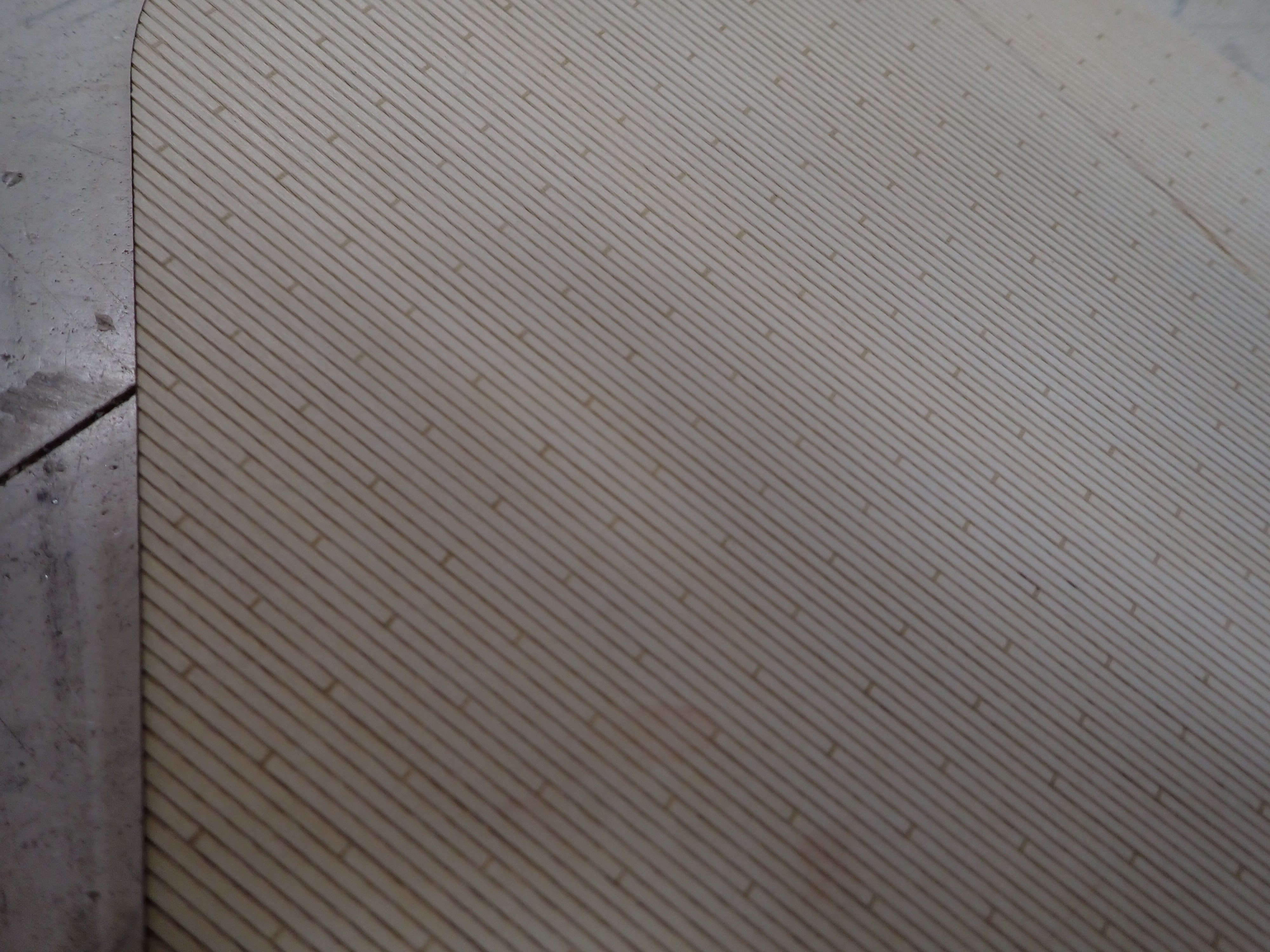
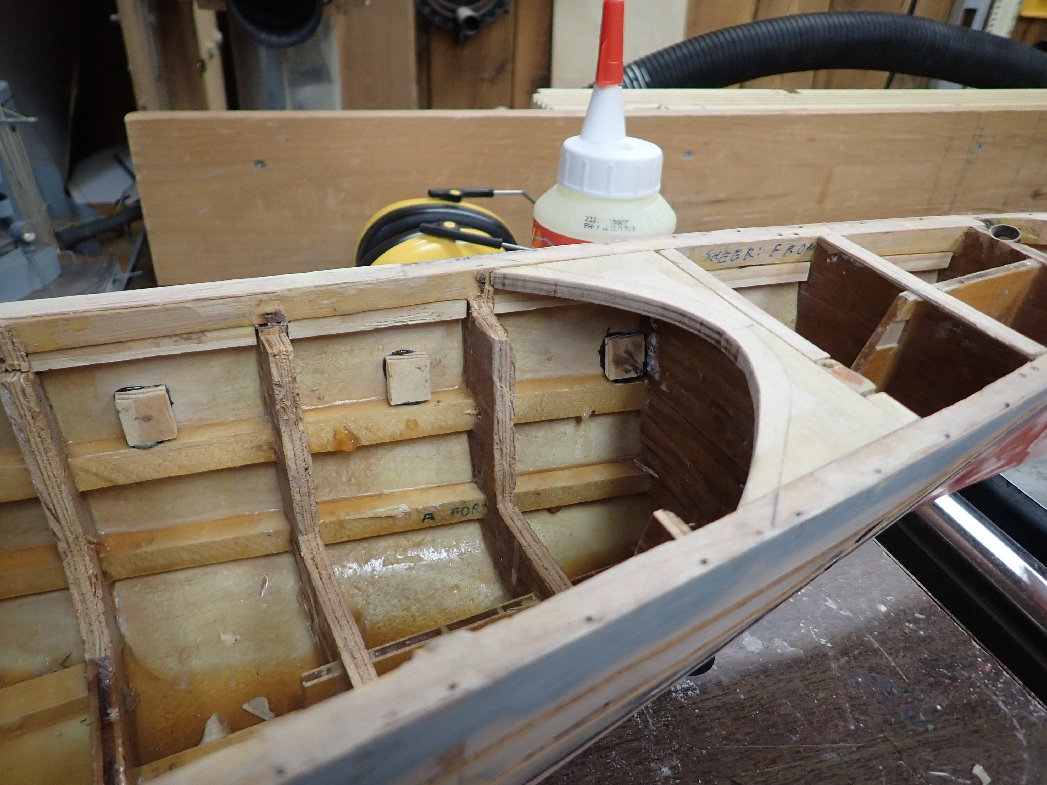
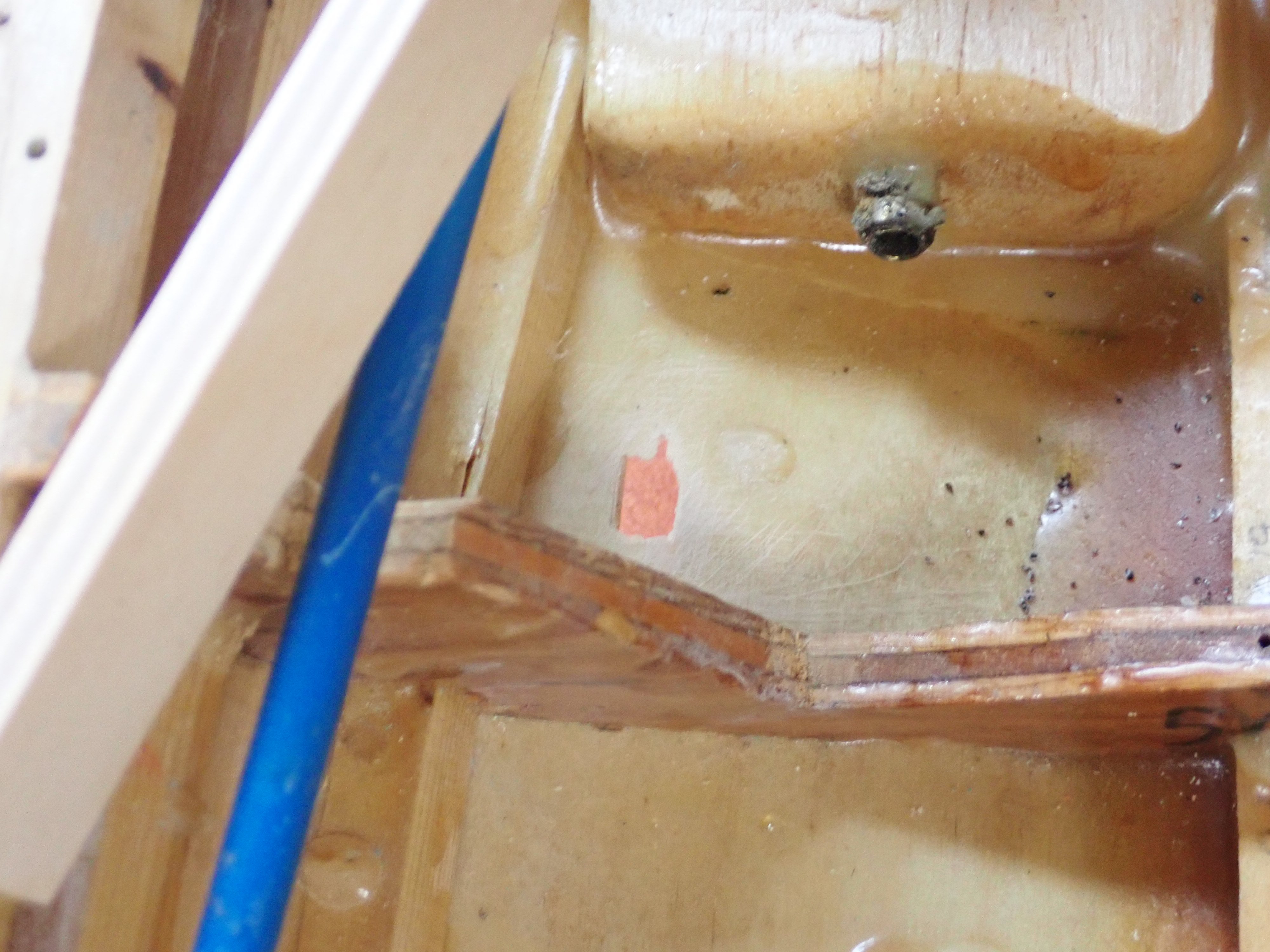
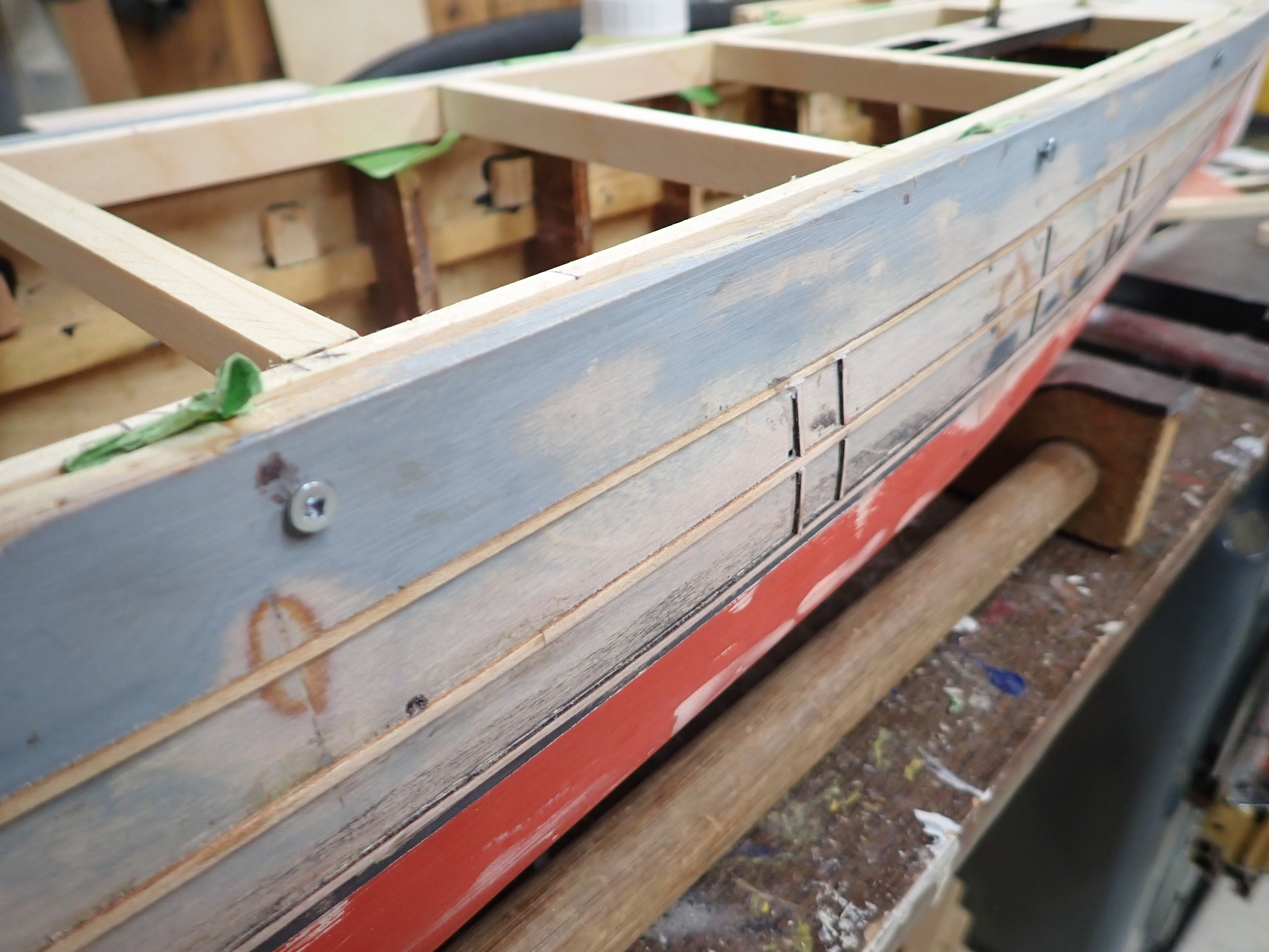
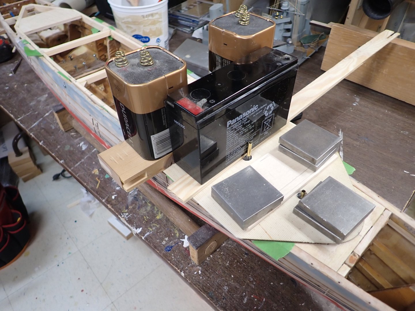
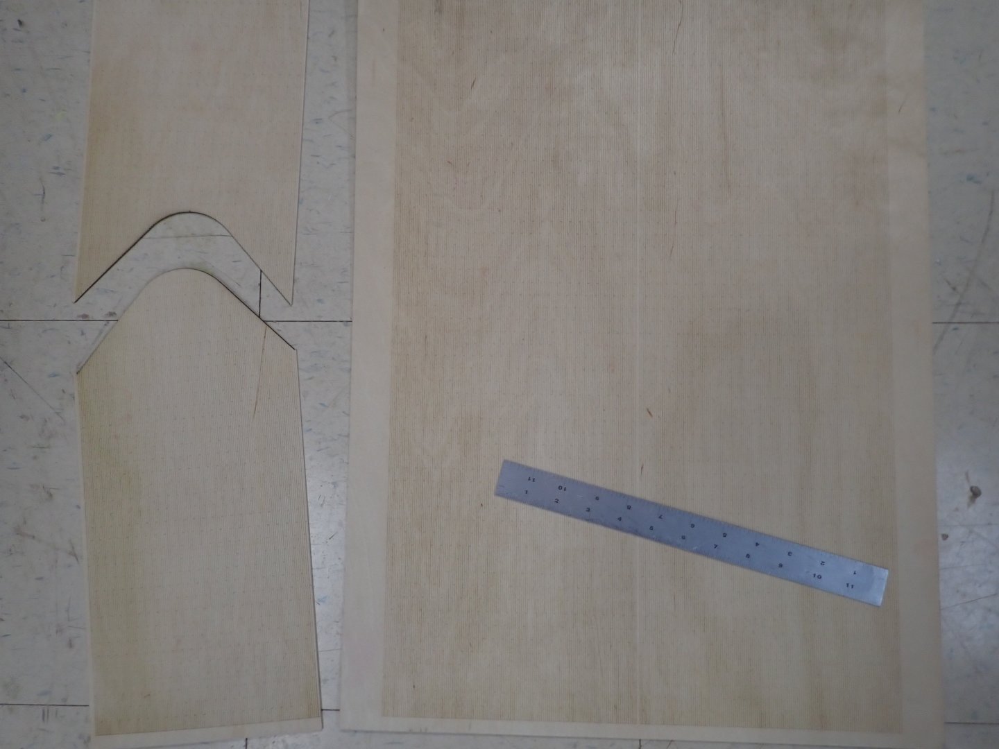
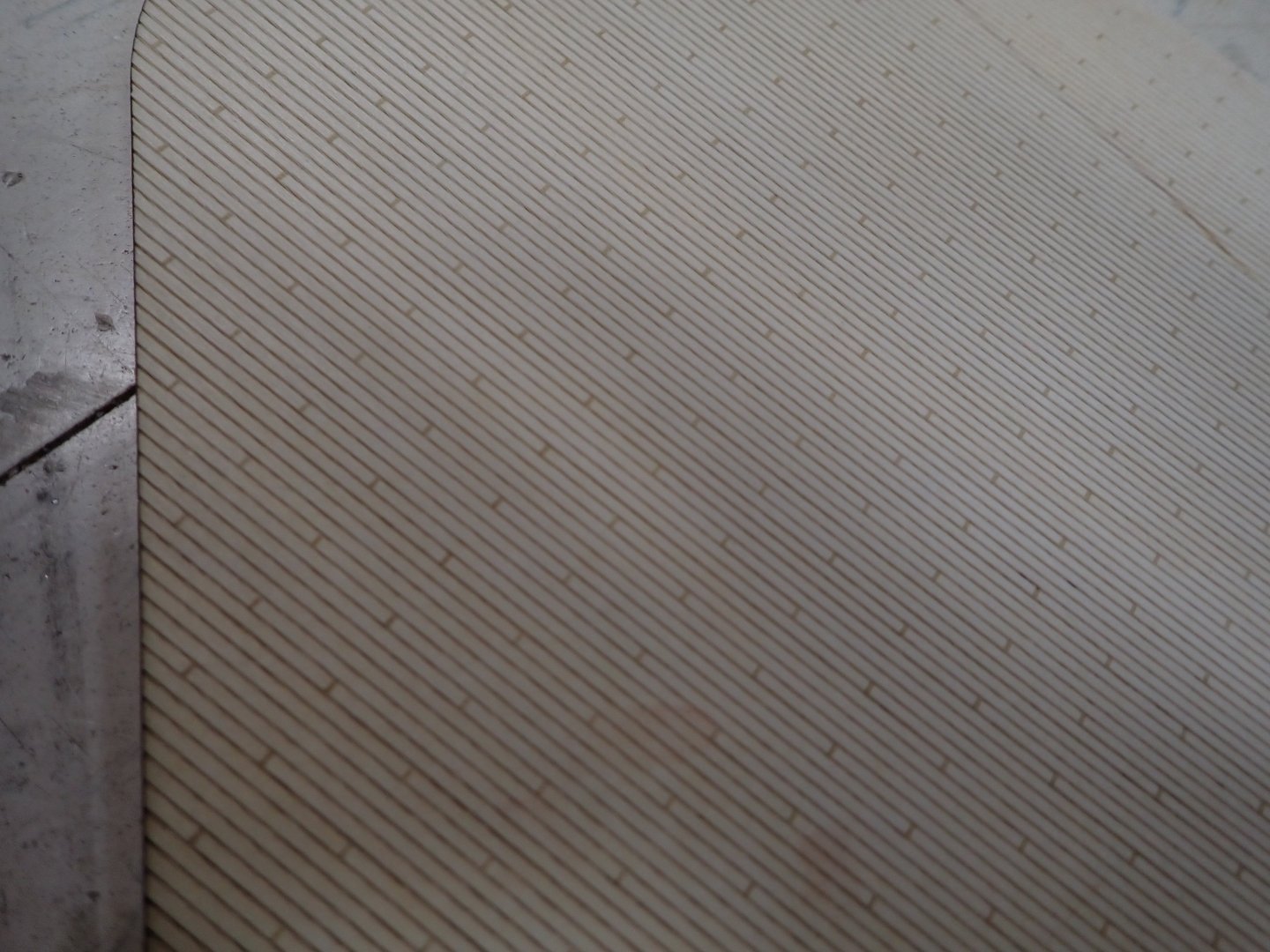
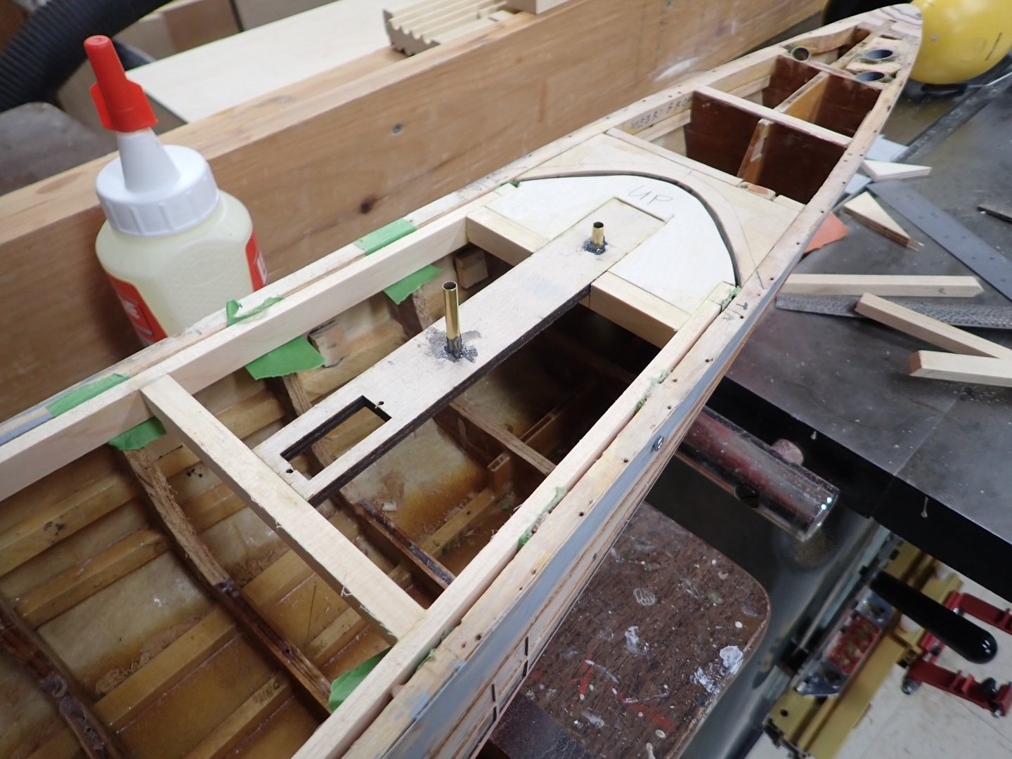
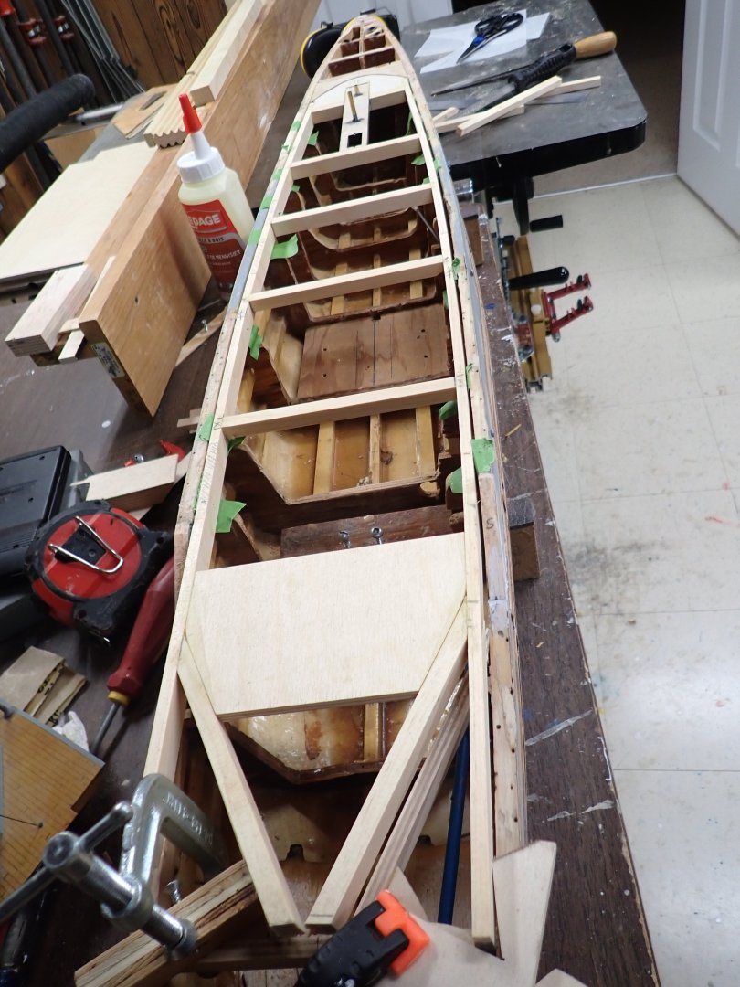
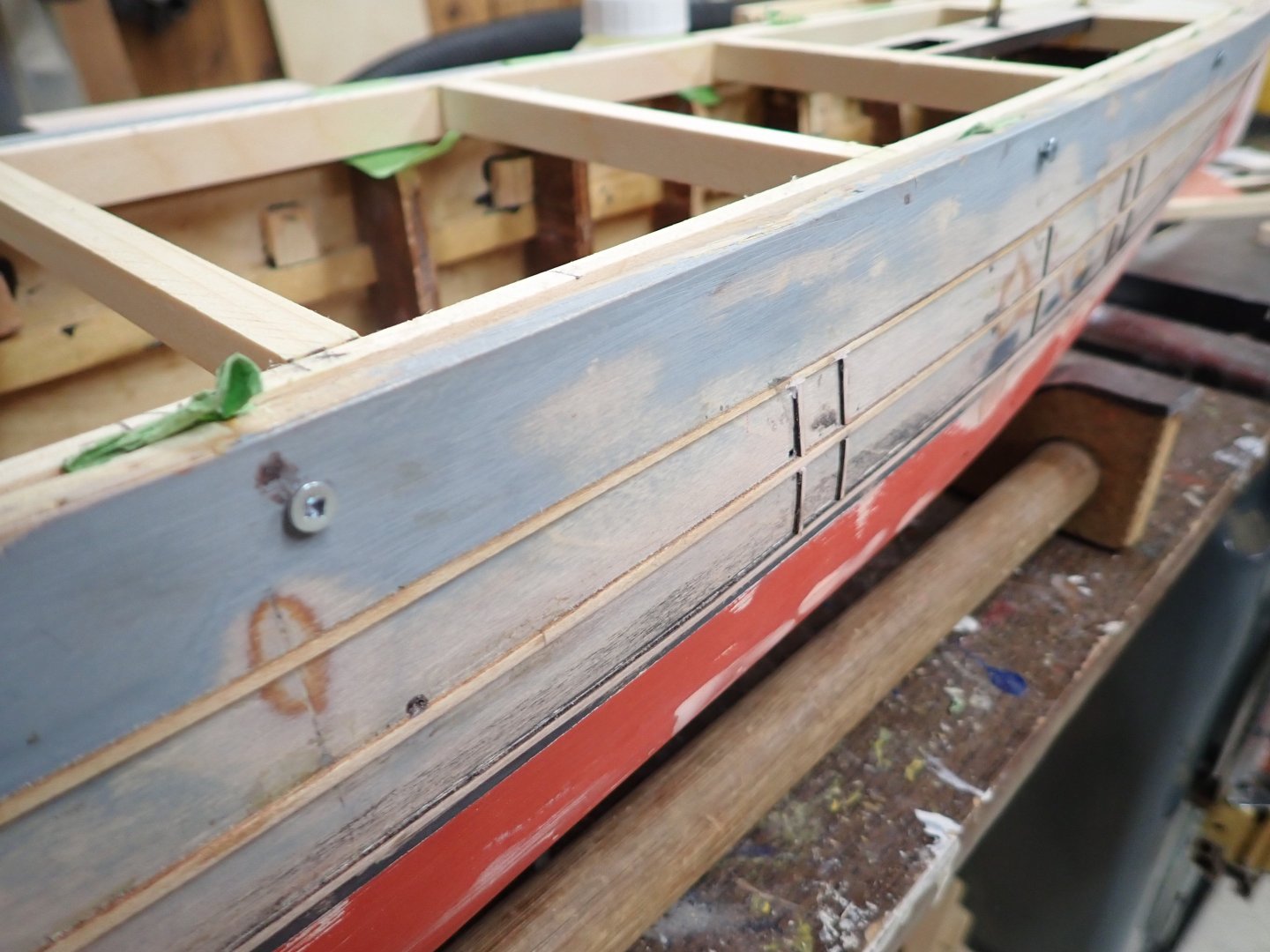
It's been a while. Not much work done over Christmas but I am making some progress now. Used the laser cutter to etch deck planking on 1/16" baltic plywood. Here's the largest piece 24"x18" with tw0 replicas of 8" wide decking, and two smaller pieces for the foredeck forward/abaft of the breakwater. I lasered these two apart following the curve of the breakwater as it seemed the best way to keep the crack less noticeable. "Planks" are 1.5mm wide, a scale 20ft long. I added strips of wood just below the bulwark stringer because the new portholes fell just below it and I wanted more to glue them into than the 1/32" ply skin. You can see these new-looking pieces below, and also blocks further down into which to anchor the torpedo net booms. Teenage me just glued them into the skin but old me is fussier. While paring material off a bulkhead, my 1/4" chisel slipped and of course went clean through the bottom. One more patch to add. While waiting for my micro eyelets for portholes I started the frame for the removable deck portion, which encompasses "A" and "B" turrets, both superstructures, and the central "Q" turret. Here we see the plywood mount for "A" and "B" turrets built into the framing. In order to make the frame, I temporarily screwed the outer strips to the inside hull, with a slight gap, letting them bend naturally. Then I filed/sanded their tops flush with the sheer line, finally adding cross members. Hope is that after adding the deck ply, the whole will retain its shape when I remove the screws (other hope is that I can glue the deck on without gluing it to the hull....that would be a major hiccup!! The fore deck continues to the aft end of the aft superstructure, where it forms the deck in this superstructure's central well boat storage. Sadly I just noticed the tapering aft end shown here is slightly twisted off level athwartships wrt the rest of the deck. Sigh. I'll need to cut out the large plywood stiffener and fix the beams, then reapply the stiffener. Temporary screws through the hull, holding the frame's outer members. Thanks for following!


-
God, that's a lofty rig!
-
I once counted up all the buntlines on the 5-masted Preussen; I forget the total but it was huge enough to convince me to omit the sails and some associated rigging on my model.
-
Glen, you're getting fast at rattlin' down. They look great! Topgallant shrouds did not usually have ratlines; I know - it's a puzzle to me too. Perhaps the "ladder" just gets too narrow to be useful? To man the topgallant yard they could lower it to the cap and access from the top of the Topmast ratlines.
- 301 replies
-
- 3
-
-
- Constitution
- Bluejacket Shipcrafters
- (and 1 more)
-
Very cool video. There's a lot to know about properly running this technology!
- 732 replies
-
- 3
-
-
-
- Lula
- sternwheeler
- (and 1 more)
-
Thank you Keith! May your family have the same! Looking forward to MSW's various 2025 build revelations..........
-
Thanks! Lion was my 4th RC build but the first scratch, so I had some experience with kit hulls. Luckily my dad's friend Jim worked in a large drafting office and he had the David MacGregor plans enlarged for me, to the size I wanted. Re-doing a sailing ship sounds pretty daunting I must say. I had that old Wasa kit in the 70's too but I made a pretty poor job of the planking. I gave up when I got to the point of "Carve these two balsa blocks into a pair of lions as shown". 🙄 Might be easier to buy a newer Wasa kit; that old one was very inaccurate.
-
One more Italian anecdote: When we booked the vehicle they said we would get a VW "T-Roc", an SUV model I never heard of; maybe the European version of Tiguan? Anyway when we clunked along the cobble sidewalks to the car place in Florence with our luggage, the guy took our reservation form and consulted his computer. Then he said, and I quote, "We don't have any Volkswagens left so I'll give you an MG". Huh? "How the hell are we going to fit with our luggage into an MG?", was my immediate thought. 🤔 Turns out "MG" is a Chinese auto manufacturer, which I also never heard of. Did they buy the "MG" brand?
-
Glen, sorry to disappoint but I don't know either. 😞 Hey, I'm an electrical guy not an aeronautical fluid dynamics guy........ On the subject of the Coriolis effect, when we visited the equator in Ecuador they demonstrated it using a plastic sink on legs. On the equator, the water simply ran out with no spin. Four feet north of the equator, the water spun out CCW. Four feet south, it spun out CW. I was amazed at this demo and will never forget it.
- 185 replies
-
- 8
-
-

-
- Flying Dutchman
- Black pearl
- (and 2 more)
-
Thanks! Summers are for RC boats and days can be hot here. I was advised by the local 3D shop to use PETG not PLA since as you say it can warp. ABS is not an option for us due to fumes which would be deadly for our parrot; nor is my printer enclosed for fume safety. I'm not planning on printing hulls; I just want to print some parts for the superstructure, and the stacks. Looking forward to seeing more of your build! Ian