Ian_Grant
-
Posts
2,156 -
Joined
-
Last visited
Content Type
Profiles
Forums
Gallery
Events
Everything posted by Ian_Grant
-
 Eric, you could try PM'ing "Dafi" about the number of gunport lid ropes; if anyone would know, he might. Also, did you order the entire set of 108 "SoRo" guns from HISmodel? They look fantastic in their photos! I noticed their diagram of assembling the upper deck gun carriages by gluing the side pieces to the side of the bottom piece, rather than along the top edges of the bottom piece, to increase the width of the carriage. Makes sense. Remember to glue the wheels on closer to the front and back of the carriages for a better look. Heller has the axles too close together....👍
- 453 replies
-
- 3
-

-
- soleil royal
- Heller
- (and 1 more)
-
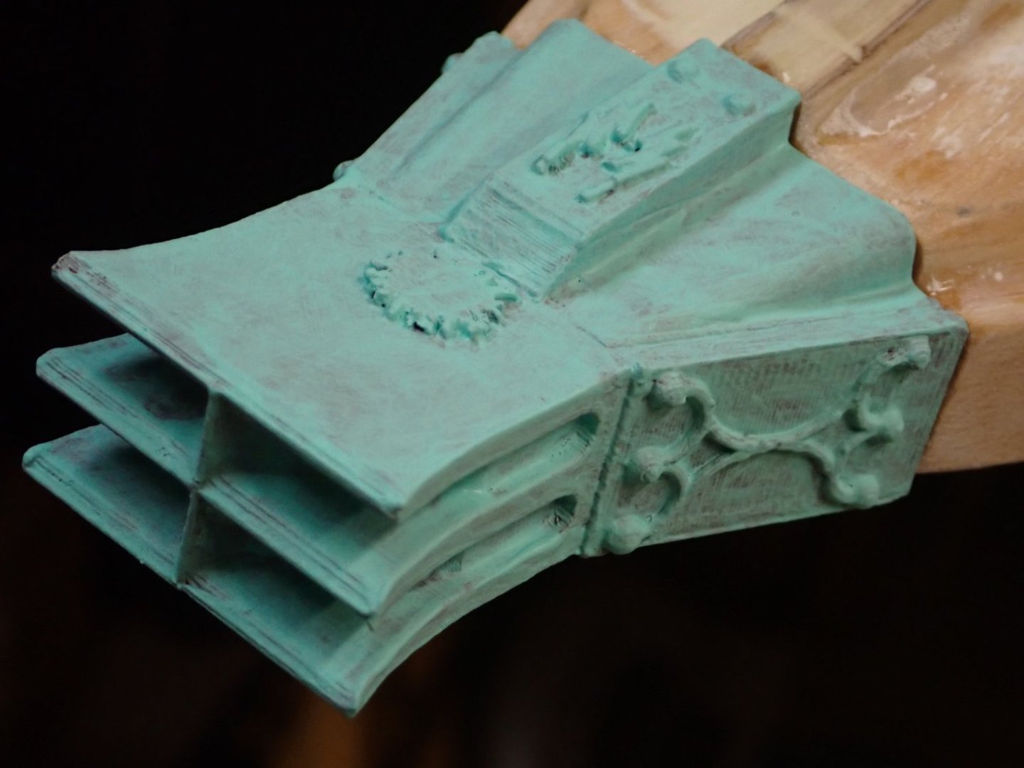
You could be right .... I've never seen an ancient galley ... looking at photos of "Olympias" the ram looks like a pretty uniform verdigris green all over. I may add a little more; I don't want to simply "paint" it opaque verdigris.
- 536 replies
-
- 3
-
-
- Quadrireme
- radio
- (and 1 more)
-
Thanks guys, I will just clear-coat it and consider it finished. Got the ventilation strakes glued onto their black backgrounds today. She's coming together! I'm happy.
- 536 replies
-
- 2
-
-
- Quadrireme
- radio
- (and 1 more)
-
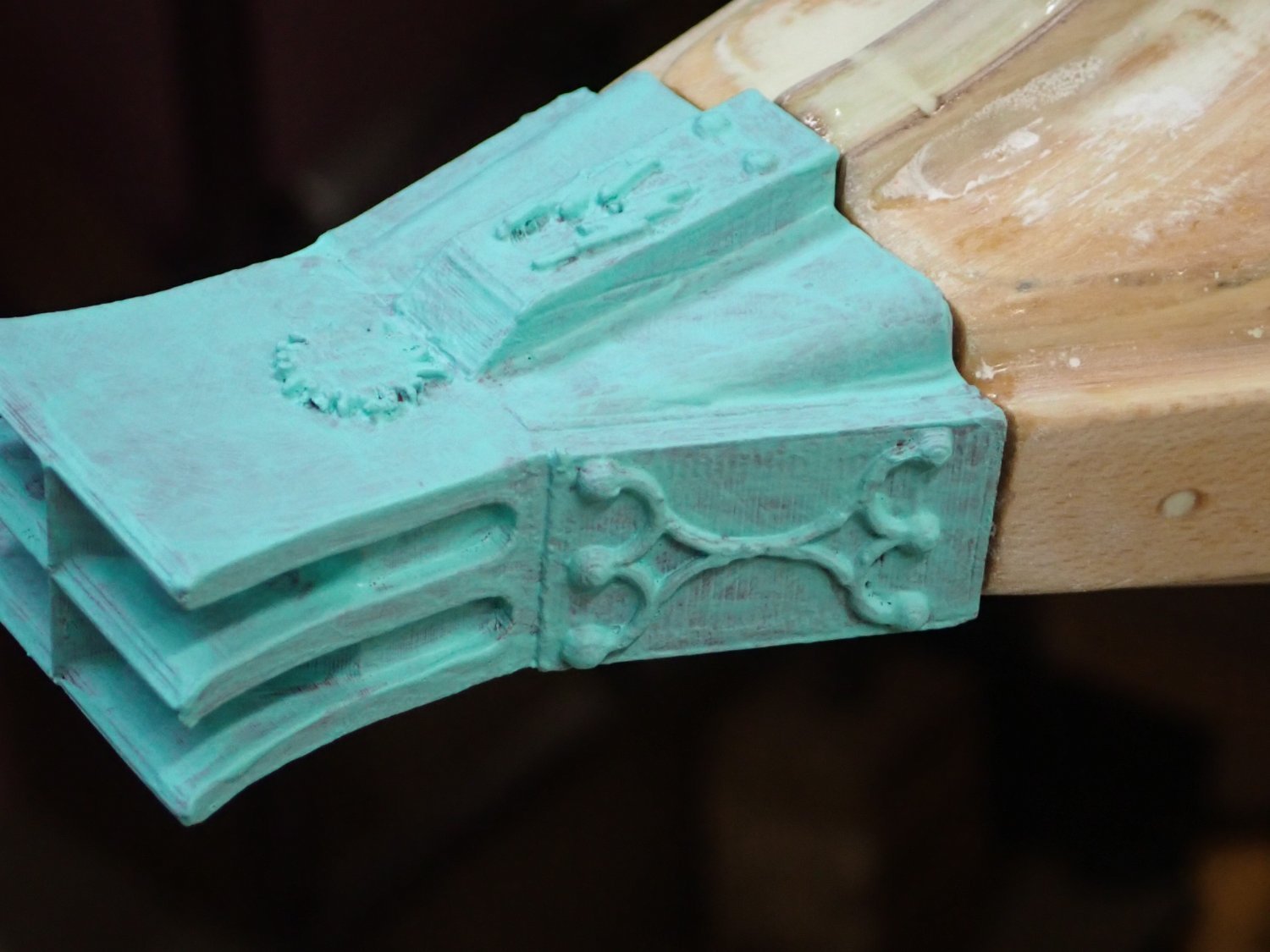
When I went to the hobby shop to get some paint the other day, I happened to notice Vallejo Model Colours "Verdigris Glaze" and thought, "Aha! Just what I need for the ram!". Over the last two days I have applied three washes of this verdigris, after painting the ram a bronze-like brown (the "bronze" paint was out of stock). Picture below. By the way, I really like these Vallejo paints better than the Humbrol tins which seemingly can't be found over here now. What think you? Do I need to apply a wash of white at some of the projections? A little black? To me it looks pretty good but .....

- 536 replies
-
- 10
-
-
- Quadrireme
- radio
- (and 1 more)
-
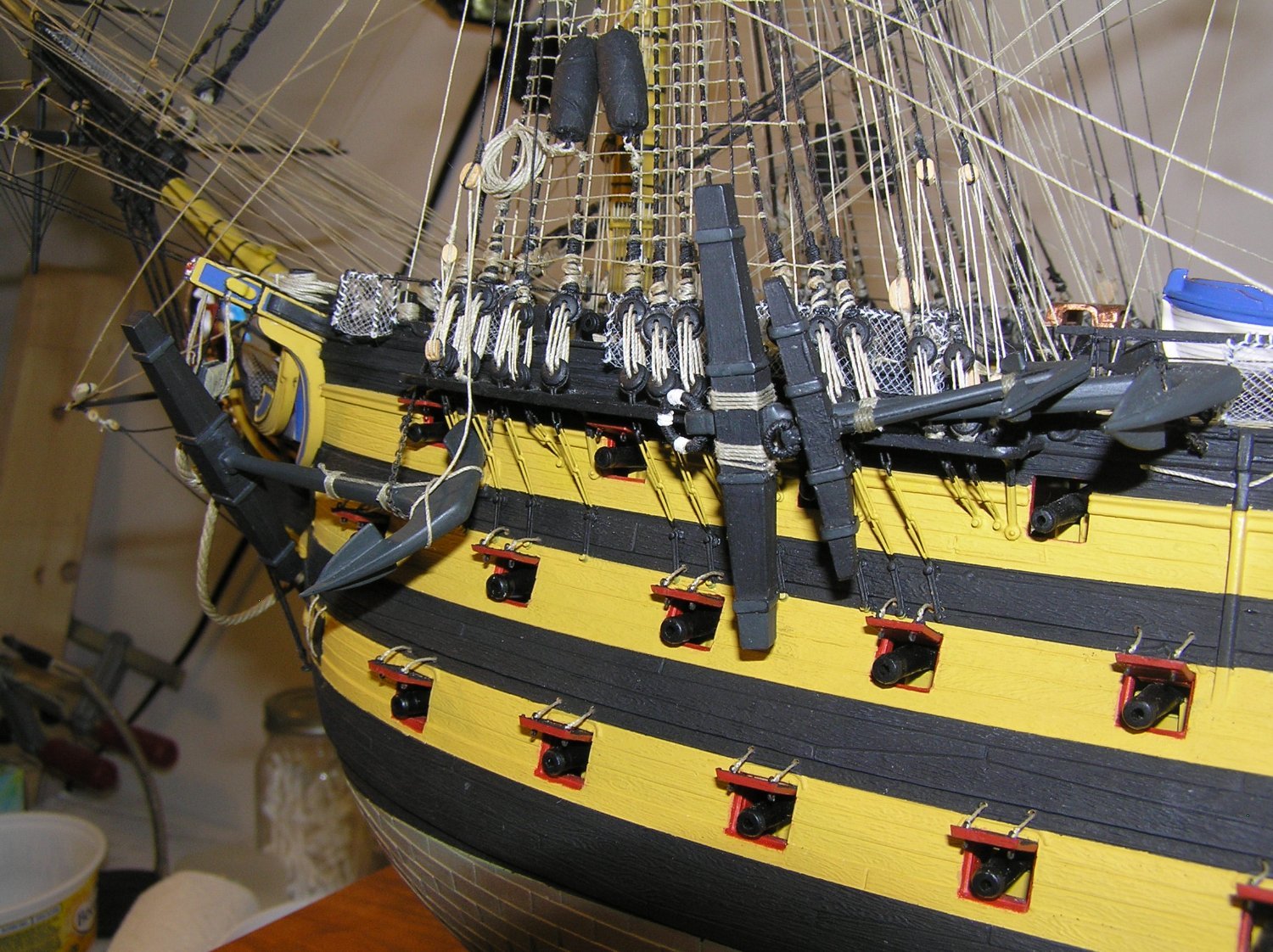
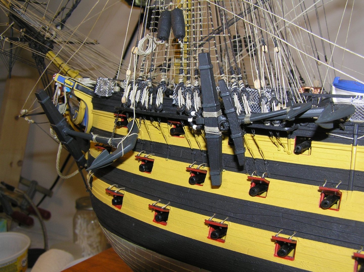
Eric, IMHO those are too large. I recommend Caldercraft #83505 brass etch eyes seen below. I used many on my 1/100 Victory; two on the outside and two on the inside of each gunport lid (and various other locations). https://www.cornwallmodelboats.co.uk/acatalog/caldercraft83505.html#SID=3190 While I'm on this topic, you can also replace the Heller plastic eyes with copper equivalents if you so choose. They give you confidence that no eye will break as you rig it. https://www.cornwallmodelboats.co.uk/acatalog/caldercraft83500.html Here are the #83505 eyes on the lids.
- 453 replies
-
- 3
-
-
- soleil royal
- Heller
- (and 1 more)
-
Good eye. I wasn't sure of true scale either. I know after the corvus became obsolete (partly due to its weight's adverse effect on seaworthiness) they used relatively light-weight "boarding bridges"; Pitassi also mentions that the "towers" became light, collapsible affairs which allowed them to be lowered and stowed when not used. They weren't meant to actually be like protective castles for the archers apparently. My 1/16" ply is a scale 2" which is my interpretation for "collapsibility"; according to Steven ("Louie Da Fly") these ships' actual hull "ribs" were only 2" x 2" members to keep the structure light and nimble for human power.
- 536 replies
-
- 3
-
-
- Quadrireme
- radio
- (and 1 more)
-
That's what we do here at Model Ship World !! 😁 Eric, you can get free Heller replacement parts! The Heller parts replacement source is Glow2Be in Germany. Go to the "glow2be.de" website, click on "Service" then "Spare Part Form" , print the pdf file and fill it out. I tried scanning and emailing to the address given on the form but it would not go through as the "glow2be" server would not accept messages from my "domain", be that Canada, North America, or whatever. I then FAXed the form to the number given and was rewarded after two days with news that a free part had been shipped! Customer service! Good luck, Mr. Phelps....
- 453 replies
-
- 1
-
-
- soleil royal
- Heller
- (and 1 more)
-
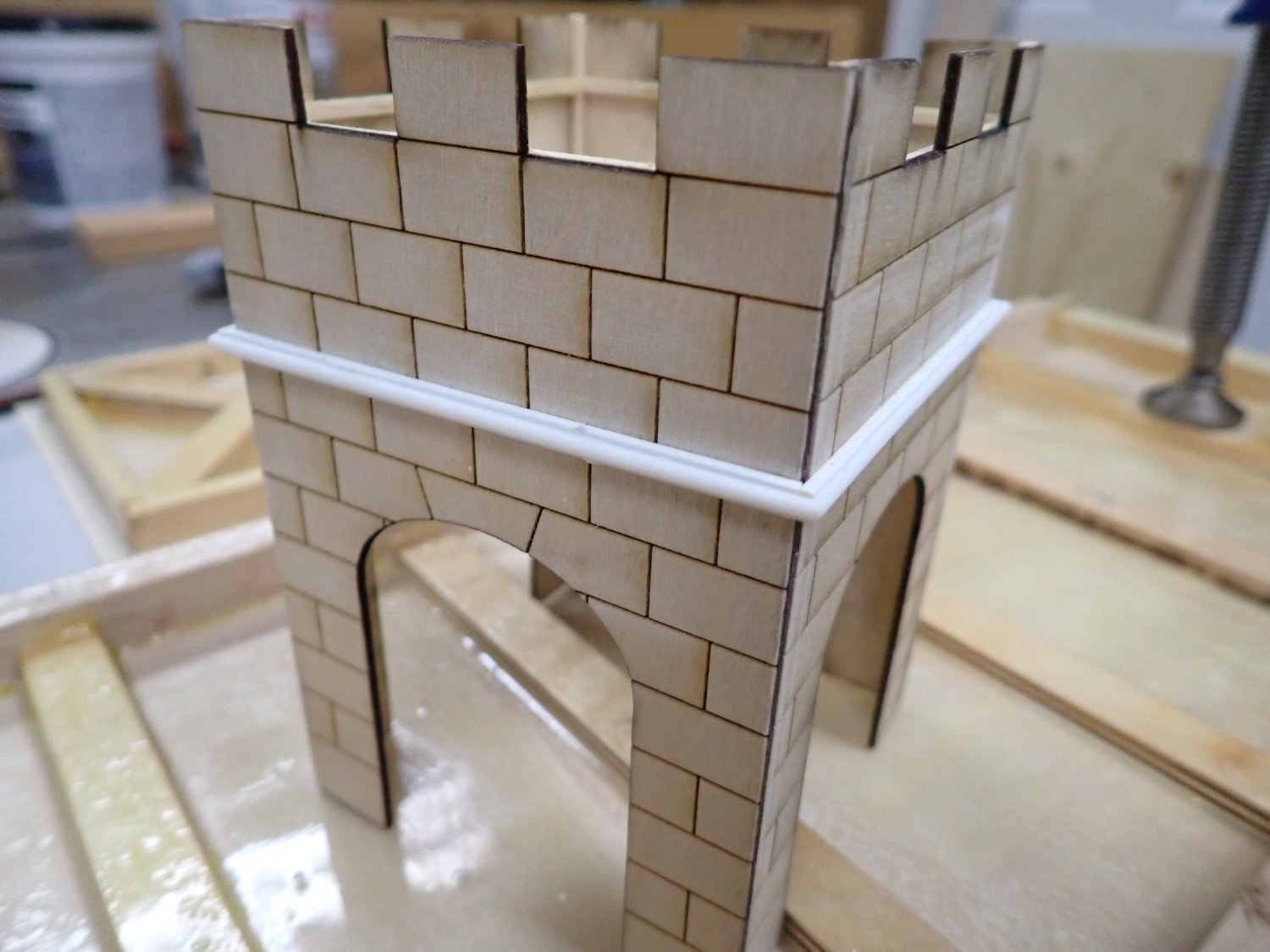
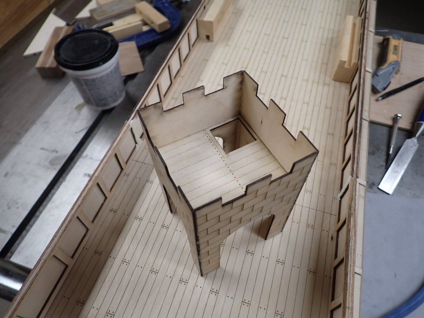
HaHa! Vic, no patience was involved; I just drew some lines in the Inkscape program and the laser cutter machine etched the "blocks" into the surface for me. (and then cut out the full walls too).
- 536 replies
-
- 1
-
-
- Quadrireme
- radio
- (and 1 more)
-
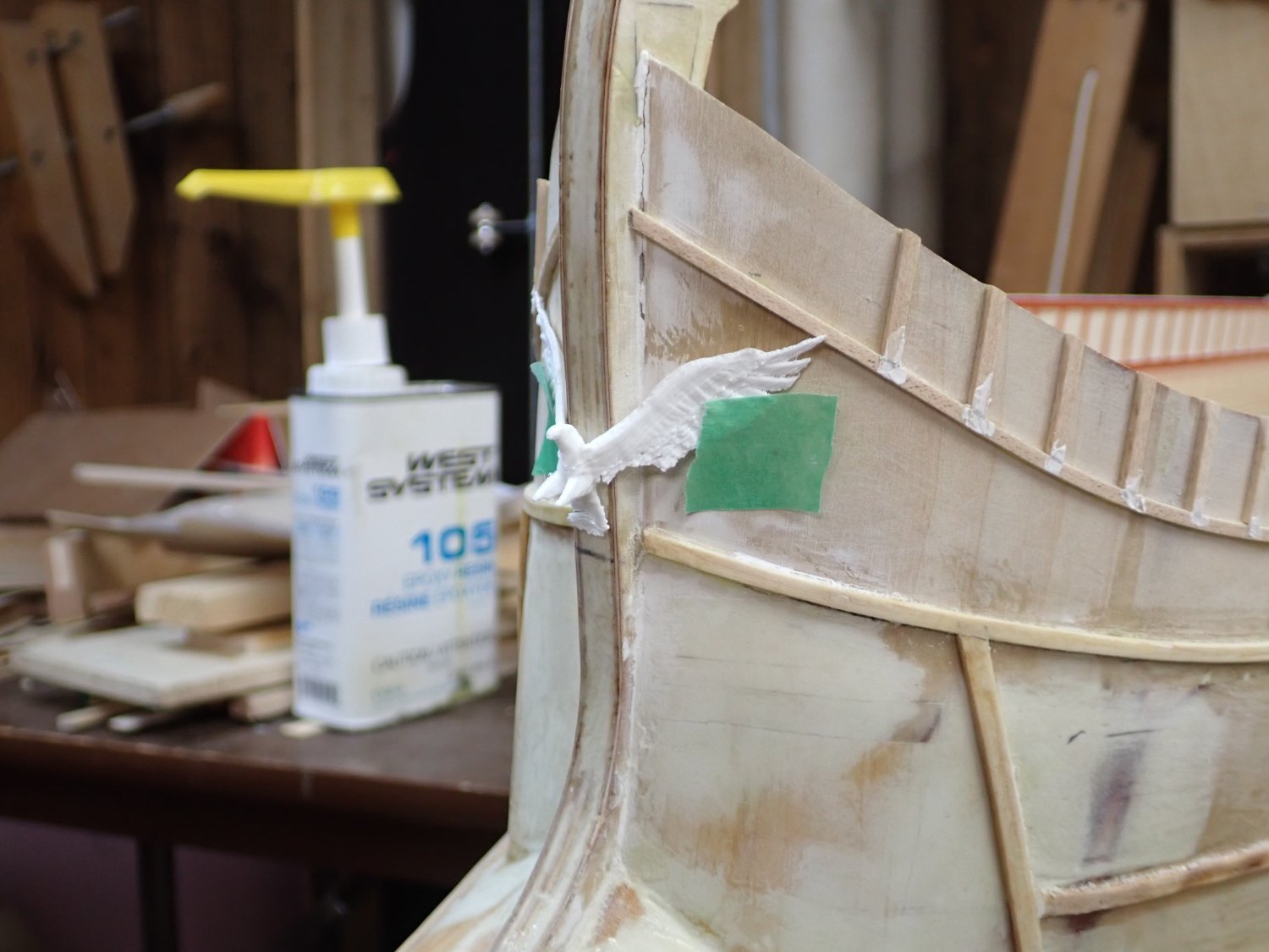
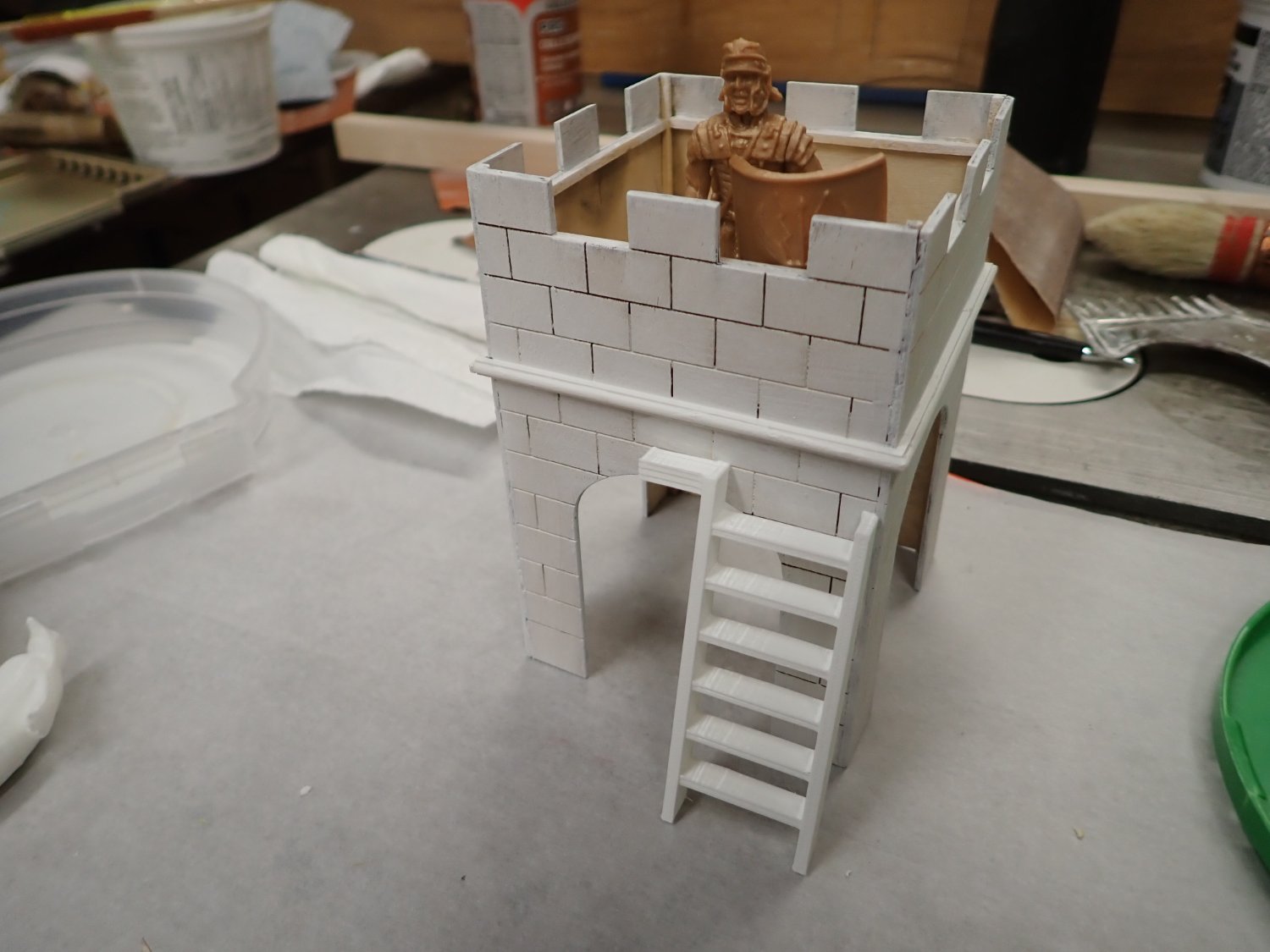
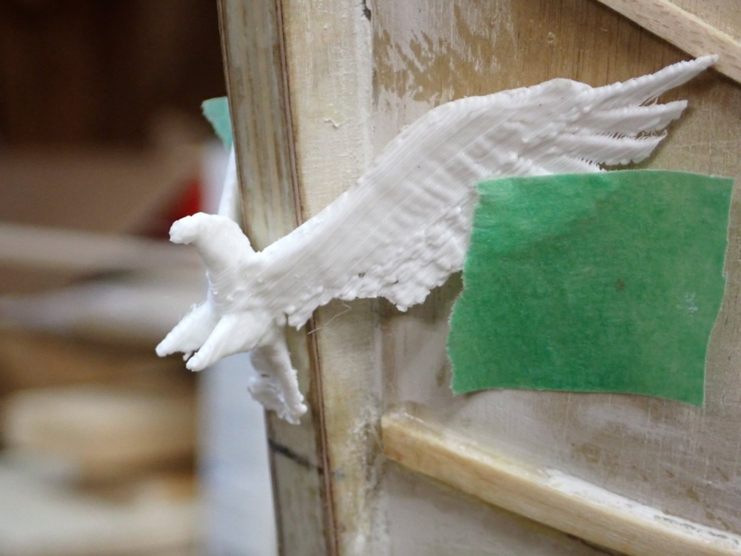
OK so I got the bulwarks glued down to the main deck section, and varnished all decks/outrigger tops/steering platform decks with Minwax exterior diamond finish. It gave a very nice finish, but it's more like a regularly polished dance floor than a ship's deck. Also, the grain of the ply surface became more visible so you can see it continuing across planks. I'll need to experiment with some washes to disguise and age it a little. Not too much because I don't want to have to age all the paintwork too. I spent some time today 3D printing at the library. Here is a ladder for under the archery tower hatchway, leaning on the outside for now. Pretty simple to draw and less than one hour to print, with a final cost to me of 64 cents. Tower exterior is white primer. Marcus enjoys the view. I also did a trial print of the eagle for the bow. This was a bit tricky as I had to edit the bird in TinkerCAD to spread its wings more out to the side to match the angles at the bow. TinkerCAD is a bit limited, but so too is my CAD knowledge. I managed to break off all its talons trying to cut off all the printer supports, plus the beak is a bit lumpy due to the PLA printing process and resolution. Should I decide to go ahead with this it will need to be resin printed to give clean details.


- 536 replies
-
- 7
-
-
- Quadrireme
- radio
- (and 1 more)
-
Mike, thank you very much; deck drawings would be highly useful in showing cabin widths etc. I have been in touch with Richard and also Terry Karlsen. Waiting to see what Terry might forward to me.
-
Just noticed the activity in this thread....I did receive an email acknowledgement from Terry Karlsen at Parks Canada, who was forwarded my message by his colleague Richard Zaidan. This was the 19th December; he requested some more details as to what I was after. I replied but have not heard back....Christmas and all that..... I was going to wait another week or two then ping him again.
-
Yes that's from my copy of Geoff Hunt's print "England Expects" with the main course clew hauled up a little to provide more air for the fore course. The bunt and leech lines would be loose.
- 1,508 replies
-
- 1
-
-
- Le Soleil Royal
- Heller
- (and 1 more)
-
No, I don't have any figures. They just looked larger than I've seen on other models....
- 453 replies
-
- 1
-
-
- soleil royal
- Heller
- (and 1 more)
-
Eric, nice work. If I may say so, the fend-offs look a bit too massive in projection from the hull. Just say if you don't want more comments like this. 🫢
-
Bill; for some historical reason, clew lines on the lower sails (only) are called clew garnets. Ours not to reason why, and all that.
-
Looks great Michael! Following your build, I find ideas popping into my head for 3D printing; that bulkhead for instance, complete with decorations. I'm looking forward to seeing how you handle the deadeyes and chains. I remember looking at my kit and pondering how to use those tiny parts with actual thread shrouds. Best Regards, Ian
- 327 replies
-
- 2
-

-
-
- Sovereign of the Seas
- Airfix
- (and 1 more)
-
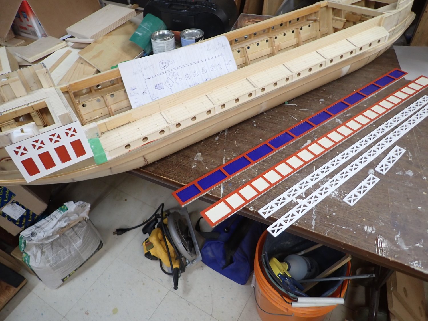
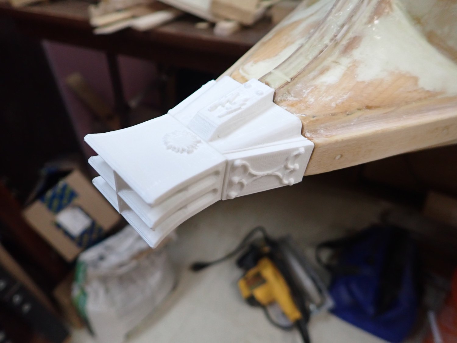
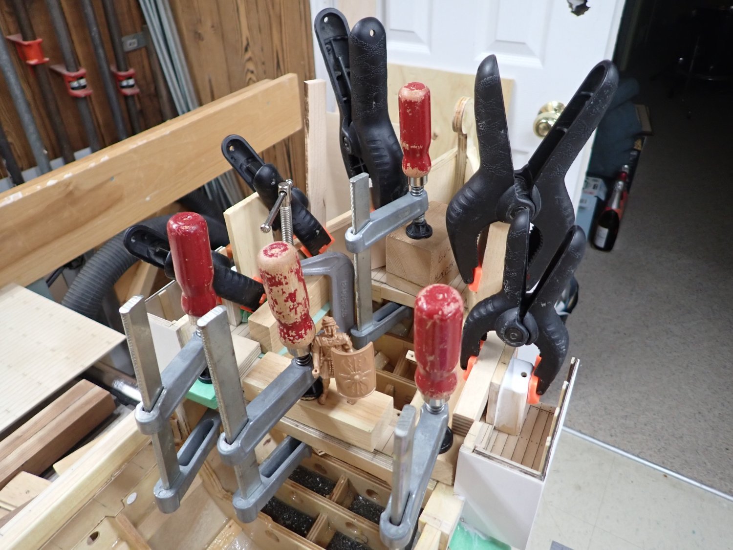
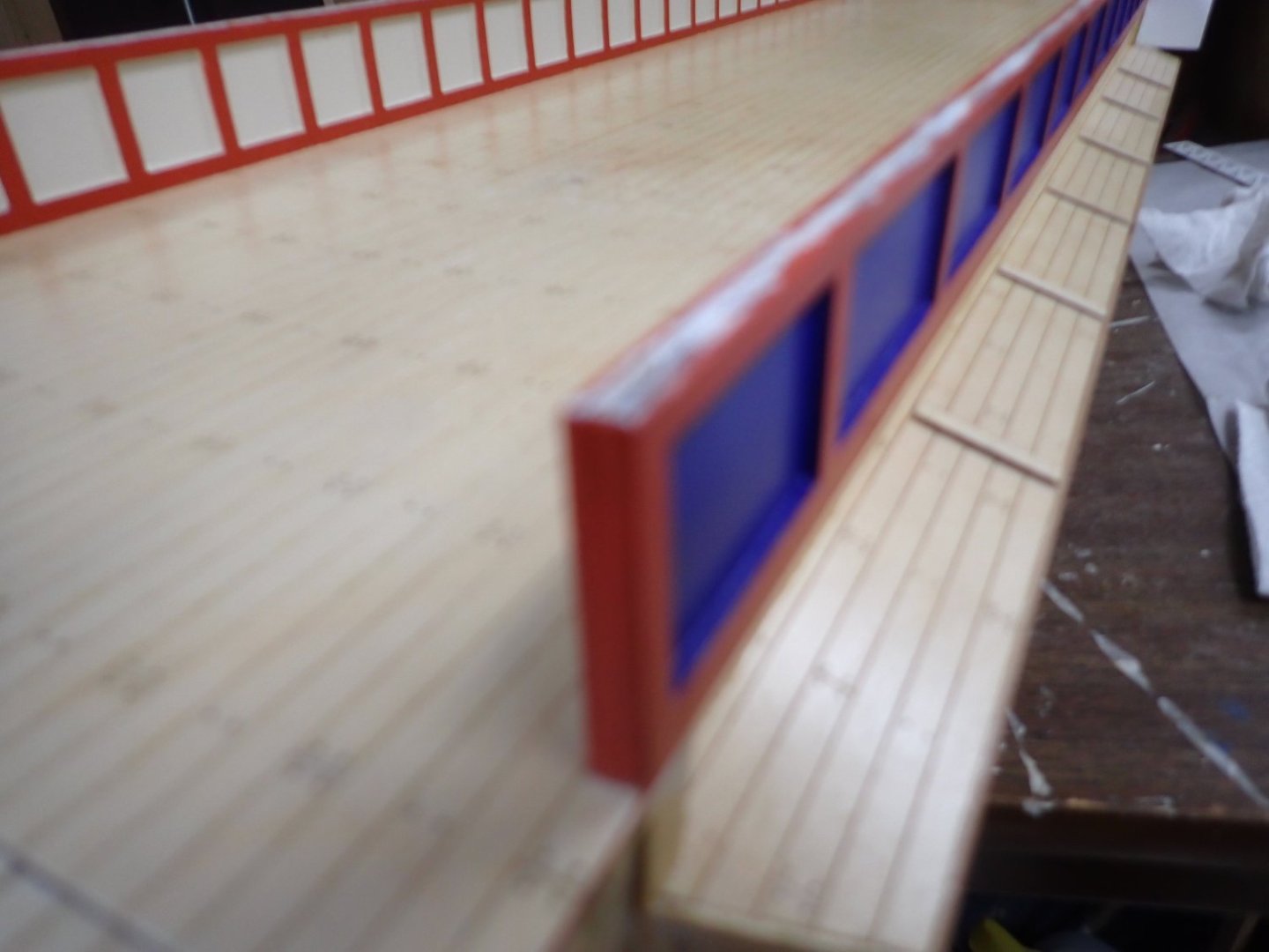
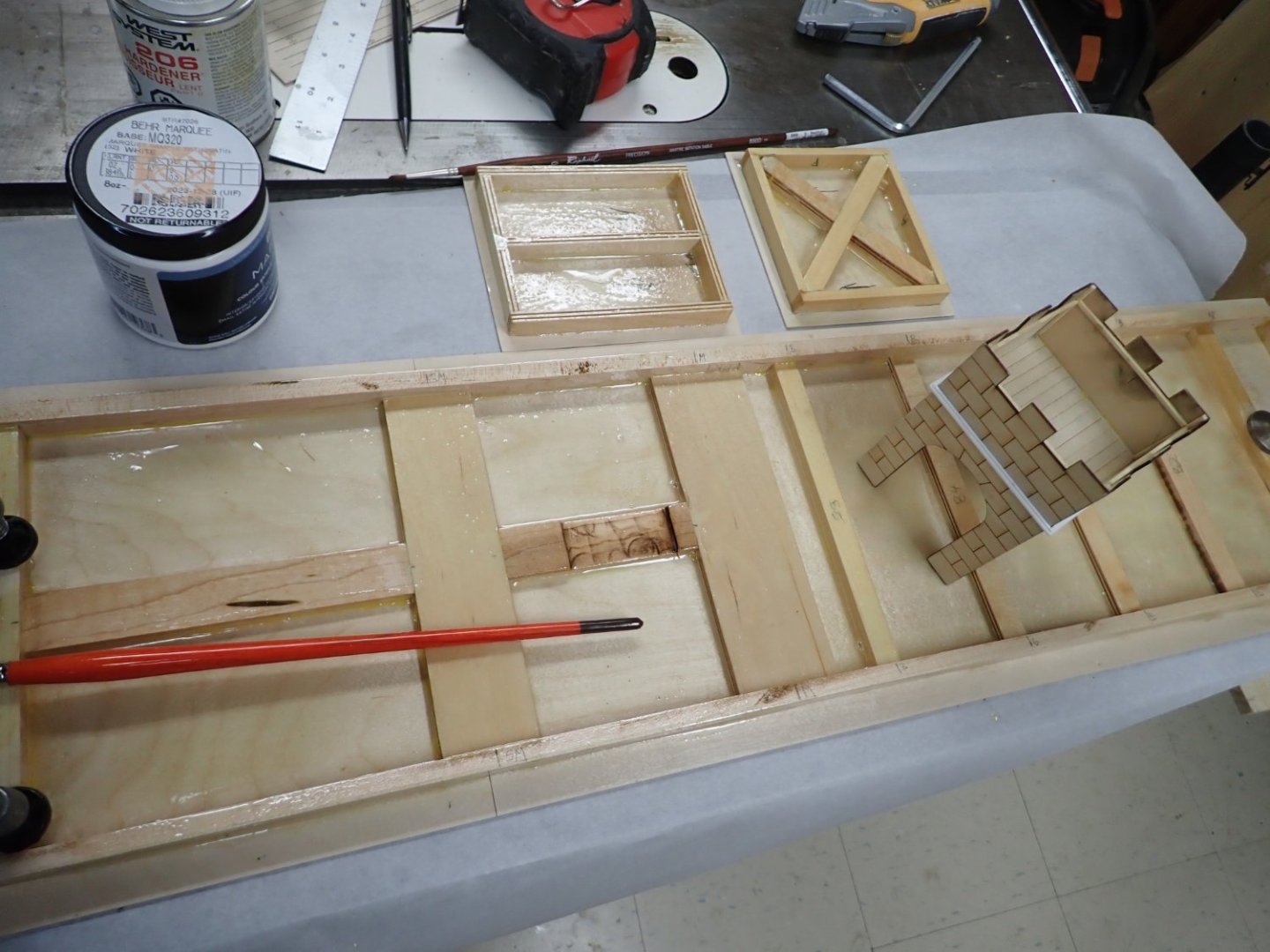
Work slowed over the Christmas holidays but I've begun painting some bits. Decorated outside walls of the steering platforms, one side of each main bulwark, and the ventilation panels. The blue panels are the outboard sides of the bulwark. With two primer coats and two colour coats it's a slow process. Made a moulding for the tower from evergreen; one strip and one half-round. Glued together "ram 2.0". It's nice and crisp compared to the ram 1.0 which was printed in one piece. Gluing on the after fixed deck. You can never have too many clamps. Marcus approves! Lastly, epoxy-resined the bottoms of the three lift-off deck pieces. Main one is staying clamped flat until I get to varnishing the upper surface. Next steps are painting the other sides of the two main bulwarks and gluing them to the main lift-off deck. Then I can varnish all the decks and finally work on the inner faces of the bow and stern bulwarks. Also need to paint the backers for the ventilation black before gluing on the white ventilation strips. If anyone is interested I am getting decorating inspiration from Flavio Terenzi's magnificent "La Nave Romana" quinquireme model, seen here: https://www.youtube.com/watch?v=LuYBk0znbB8&list=PLN8dHnRD0y61NWWulgdXo7fMLYSnjZ943&index=11


- 536 replies
-
- 10
-
-

-
- Quadrireme
- radio
- (and 1 more)
-
Very cool! Looking forward to seeing her sail. And happy new year!
-
Beautiful job! I like your soldered deadeye spacers. Happy New Year!
- 282 replies
-
- 2
-
-
-
- Bluenose
- Model Shipways
- (and 1 more)
-
Thanks Pat, for all your comments and likes this year. So close to applying paint now ..... 🤞
- 536 replies
-
- 2
-
-
- Quadrireme
- radio
- (and 1 more)
-
One of the improvements you can make is to scrape off Heller's waterline marking and paint the "white stuff" much higher up, reaching or even partially overlapping the main wale. You've probably read about that....
- 453 replies
-
- 3
-
-
- soleil royal
- Heller
- (and 1 more)
-
Always happy to follow another SR build; the more tips I can collect before I pull mine from the stash, the better.
- 453 replies
-
- 2
-
-
- soleil royal
- Heller
- (and 1 more)
-
She's looking great, Bill. You'll be done by Christmas day! What's next in 2024?
-
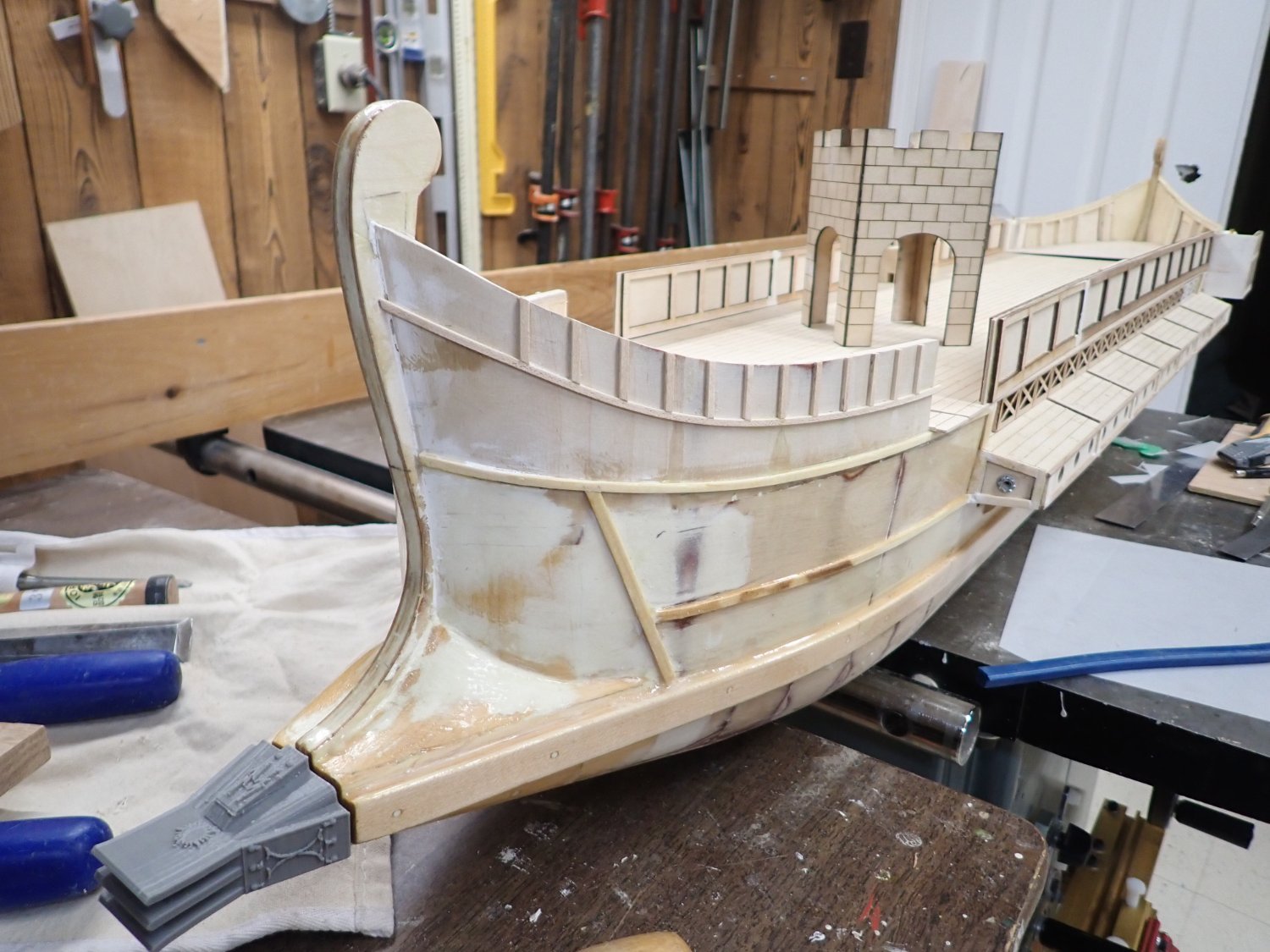
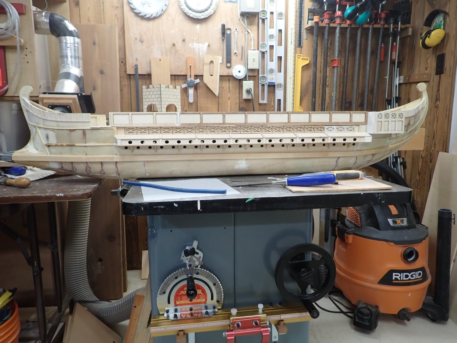
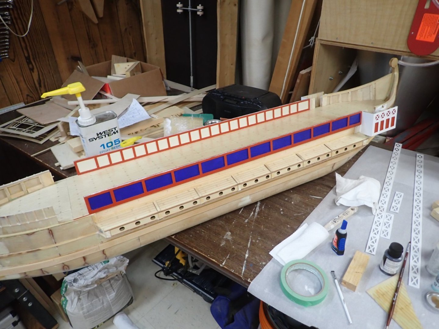
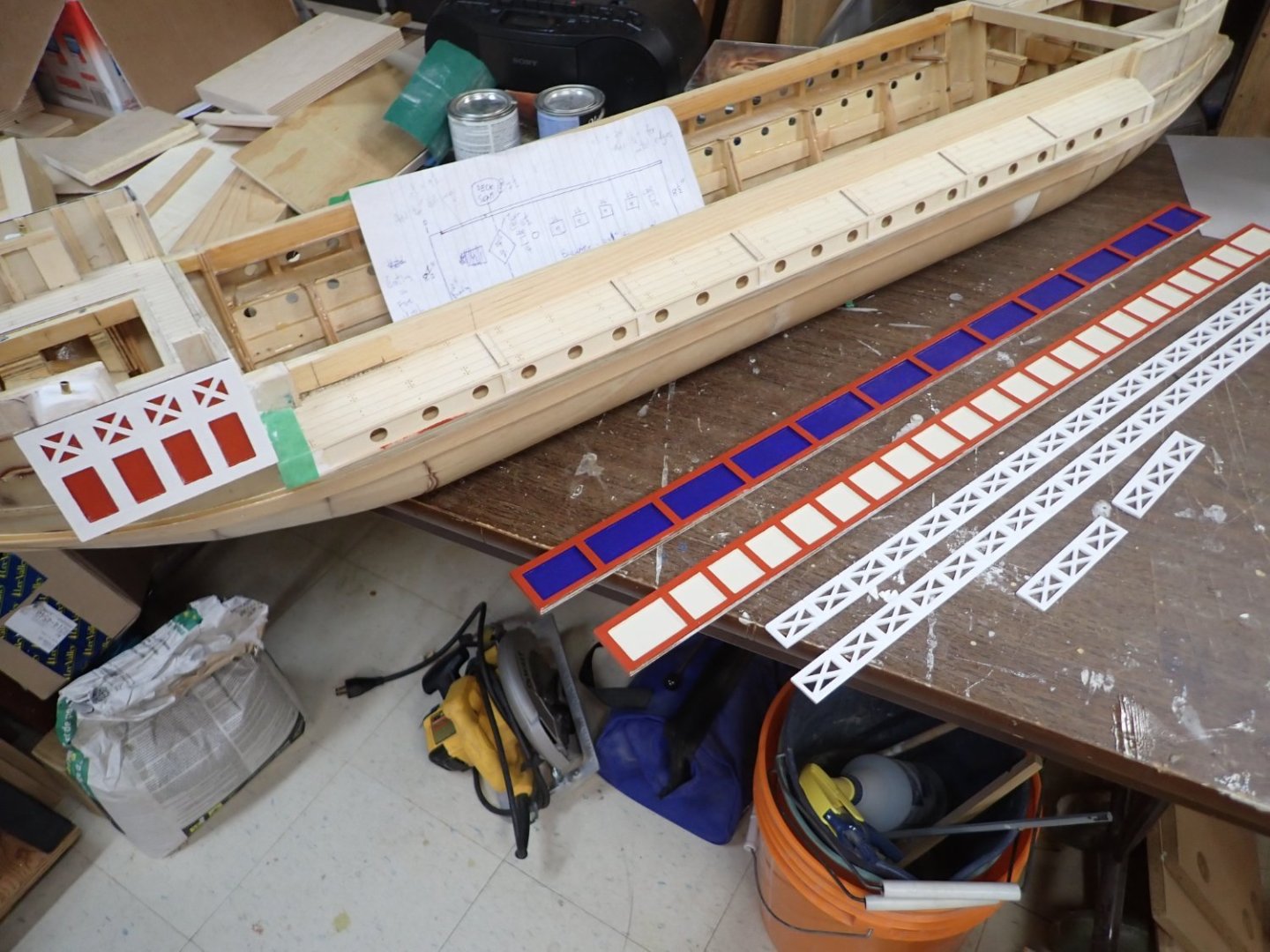
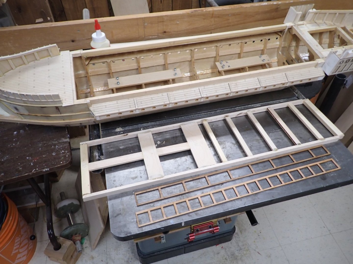
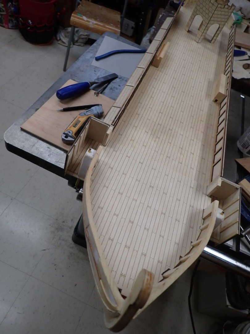
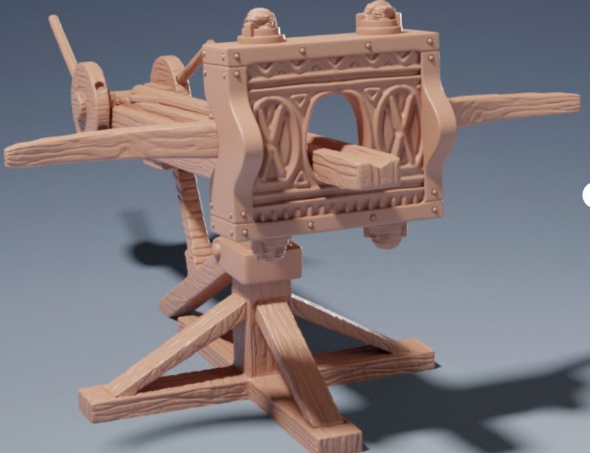
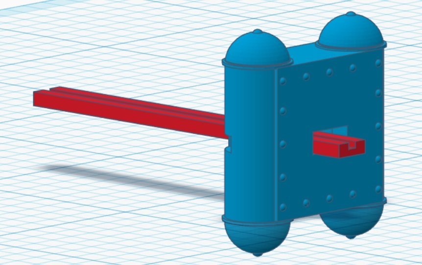
More progress shots. Framing for the major part of the deck, and laser-cut pieces for the bulwark. Smaller panels will be on the inside; larger outside panels will have the shield motifs. The beams on the aft half are spaced to allow regularly spaced ventilation hatches. There will be two access ladders to below decks; one between the tower and the mast, the other at the back of the main deck section. Just finished cutting aft deck from template. It's not glued down since the aft access hatch isn't yet cut so it's bulging a bit. Thinking of adding a little brass tube before I do glue it, to lead wires (disguised as rope) from possible "flickering LED" lantern hanging from stern fantail decoration through the deck to where I can access them inside through the hatch. Could hide the tube using the commander's cabin. Scrap blocks are supporting the unglued bulwarks. Side view looking good........pardon the two-tone bulwark frames - cutter can only do 24" and I used long cherry and short maple cutoffs I had lying around. I threw on my alpha prototype ram. Haven't glued the new 4-piece print together yet. Assembled the laser-cut pieces of the archery tower. I etched "stonework" on the outside for painting effect. Will 3d-print a ladder for inside. A bow shot. The hull is painted with epoxy resin up to the 2nd trim. Eager to start painting! Found 3d-file for a Scorpion I like better than the first ballista. File set only cost me $3. It looks like this: As compared to the stage I had reached in TinkerCAD: Not sure how much time I will have for modelling over the Christmas holiday. Merry Christmas to all! Thanks for following.


- 536 replies
-
- 11
-
-
-
-
- Quadrireme
- radio
- (and 1 more)