Ian_Grant
-
Posts
2,156 -
Joined
-
Last visited
Content Type
Profiles
Forums
Gallery
Events
Everything posted by Ian_Grant
-
 Glen, each of your builds is more imaginative than the last.......it's going to be truly unique......where did you get the eyes in the end....?
 -
Bill, be sure to touch up the black on the top of the wale before attaching the UB's; will be easier than masking later.
- 1,508 replies
-
- 1
-

-
- Le Soleil Royal
- Heller
- (and 1 more)
-
Good luck! And good work!
-
Wow! Just wow! This is so much better than fiddling with rigging tiny blocks. Daniel - I think you've found another printed product you could sell like hotcakes. 😃
- 64 replies
-
- 1
-
-
- Revell
- Constitution
- (and 1 more)
-
HaHa! I didn't notice it was another member posting....I did wonder why 'bcochran' had decided to start yet another CS instead of continuing........
- 481 replies
-
- 1
-
-
- Cutty Sark
- Revell
- (and 2 more)
-
Vitus I urge you to mount as many blocks as possible on the yards as it's much easier than adding them to yards already fixed to masts.
- 248 replies
-
- 3
-
-
- Cutty Sark
- Revell
- (and 2 more)
-
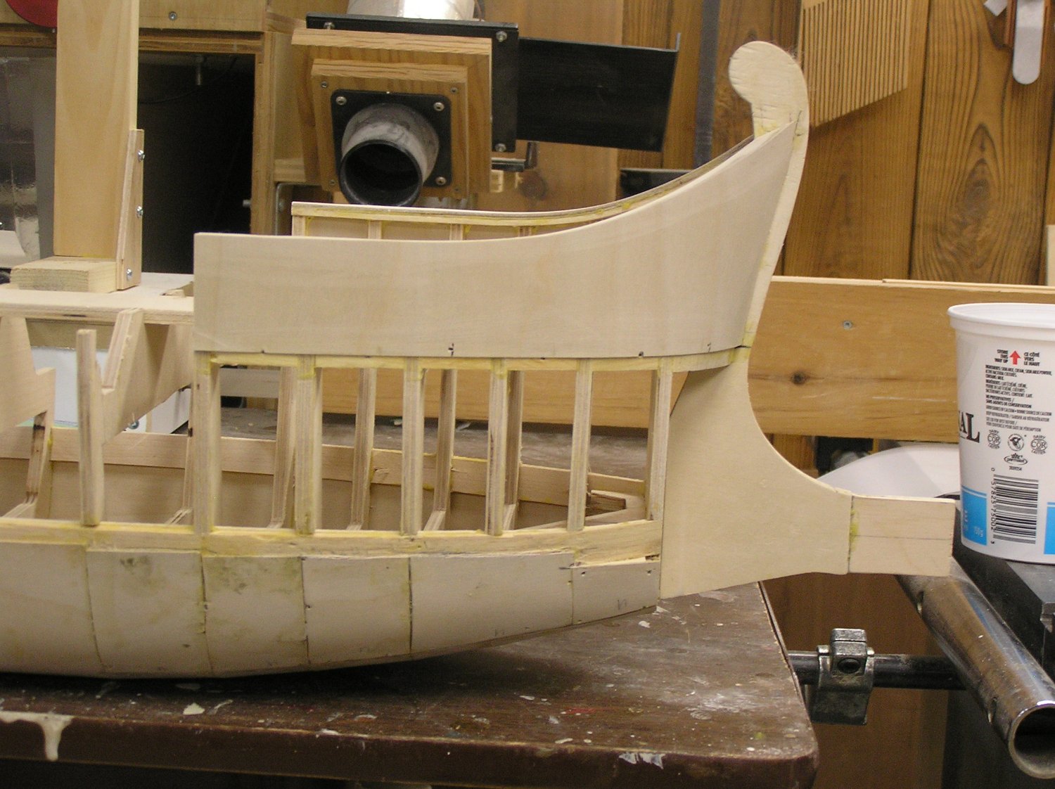
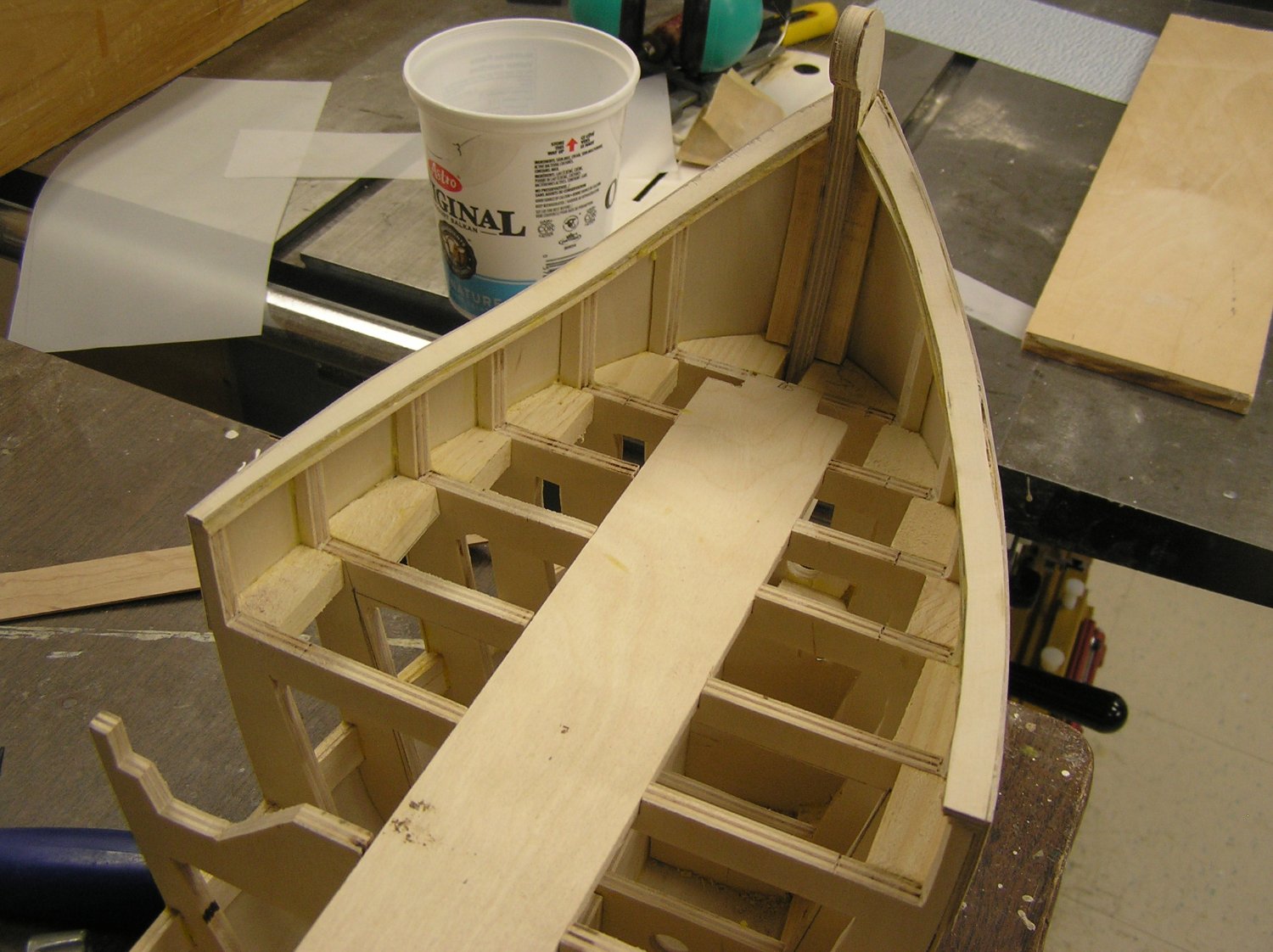
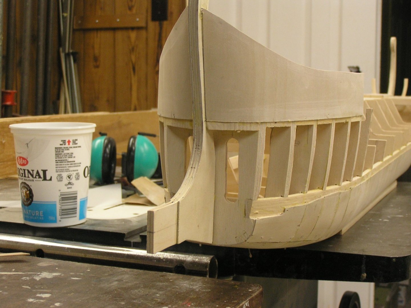
Finally finished work on my stair bannister, took many more hours than I expected. Back to the ship. I added the forward bulwarks with their sweeping curve up to the stem, and they really add something to the model. Here are some pics; note that I haven't trimmed the inner edges of the rails yet. Stanchion tops were marked on a sheet of vellum and curving rail pieces were roughly bandsawn from wider strips. They're laminated; a 3/32" strip of pine was glued to a fillet on the stem and just the tops of the stanchions, with twist ties clamping the bend down, then once dry two layers of 1/16" plywood were added with the aid of the usual paper clamps. Once dry the outer curve could be faired to the hull lines. In hindsight the ply made the edges harder to sand; I will use just pine at the stern bulwarks. The square ends of these forward bulwarks mark the gaps in the bulwarks for the boarding bridge. A cap rail will be added once the inner face is skinned. Which will be after I add the fixed portions of the deck, I guess. It will soon be time to cut out the central ribs and that long reinforcing strip along the top. Then I can start work on the outriggers. Speaking of which, I am changing the outrigger depth to 1-1/4" which will look more in scale with the hull. This necessitates a change in oar geometry; the upper tholes are 1/2" further out now than in the prototype and after studying the geometry I am lowering the upper reme tholes by 3/16" and returning to 2" oar looms from 1-1/2". The 44 oars I already made will be the lower remes; the yet-to-be-made upper reme oars will be 1/2" or 5/8" longer so their blades reach out further beyond the lower blades. I was worried the upper reme might not provide much traction if they mainly swish along in the eddie currents of the lower reme.


- 536 replies
-
- 11
-

-
-
- Quadrireme
- radio
- (and 1 more)
-
You could also buy glass "bird eyes" that carvers use. They're available in various sizes and colours like here: https://www.leevalley.com/en-ca/shop/tools/supplies/project-materials/31066-bird-eyes
-
Michael, she's impressive! What are you using for those thin ratlines (asking for a close friend 😄)?
-
Confusing diagrams, not very well drawn at vertices of the rope lines. Lines that go to the end of the jib boom are the fore topgallant stay and the fore topgallant bowlines. They pass through thimbles in one of several spans tied round the tip of the jib boom; see Longridge Fig 165 pg 235. The bowlines, part of the running rigging, simply tie off to pins on the "topsail sheet bitts" (the bitts in front of the foremast; see Longridge pg 269). You can see the bowlines running down from the fore topgallant yard in Plan #7, the foldout running rigging diagram, but they are not our concern here. I think E13 is your fore topgallant stay. The fore topgallant stay ends in a tackle arrangement (Longridge pg 223) connected to an eyebolt on the front face of the port knighthead (see top of Plan # 10 on pg 266), not the gammoning. The end of the purchase is frapped around itself as the fore topgallant stay is only rarely re-tightened. Possibly the gammoning was used in an earlier era as I have seen such on 17th century ship models. Note that you will need to add three eyebolts on the front face of each knighthead, for the tackles listed in Plan 10. I think E12 is your jib stay, although badly drawn in your bowsprit Figure. It attaches to a "traveller" which slides along the jib boom (see Longridge Fig 165 again, pg 235). The jib stay is described on pp 224-225. From the traveller it passes up and through a sheave on the side of the fore topmast just below the cap (see Plan #9 just before pg 229) and ends in a tackle to one of the trestle trees as Longridge states. You can see E12 in your drawing running up to below the topmast cap. The purchase of this tackle runs down the foremast to a belaying pin on the "main top bowline bitts" (just behind the foremast; see pg 269). This is because if they want to shift the traveller position to ease the helmsman's task (shifting the jib back and forth alters the tendency of the ship to yaw into or away from the wind at a given trim and course), they must be able to adjust the total length of the jib stay. Both these stays are seen in Plan #6, the foldout standing rigging diagram. You can just make out an indication of the traveller near the tip of the jib boom if you squint at it. Fabricating the jib traveller is challenging, depending on what level of detail you want, but is a great addition to the model. Forewarning - there is also a flying jib traveller for the flying jib stay, which slides along the even smaller flying jib boom. It's even more challenging to make. Longridge always has the information, but it is a challenging book to sort through. Really for the plastic modeller it all boils down to pg 204 to the end; everything before that (except for some diagrams) is only of concern to those making a wooden hull. I read through the rigging chapters many many times while waiting for my son to change at hockey practices and games years ago, and many times again more recently to help answer questions from Bill. 😄 Happy modelling!
-
Marc, simply clicking on "WOW" doesn't cut it for this magnificent work!! We need a button for extravagant superlatives; maybe one for "supercalafragilisticexpialadocious" 😃. Really enjoying watching your progress. Ian
- 2,699 replies
-
- 4
-

-
-
- heller
- soleil royal
- (and 9 more)
-
You're right, the old Revell instructions show no lines through these sheaves. They're empty in my old CS; what did I know in the 70's? I'd say for sure the lower lifts use these sheaves. I'd bet on topsail sheets too before the days of the split topsail. With split topsails like CS I am not sure. You'll need a book specific to CS. Nice work!
- 248 replies
-
- 2
-
-
- Cutty Sark
- Revell
- (and 2 more)
-
Makes sense to me. Bad enough having flying wood splinters, never mind flying shards of glass.
- 2,699 replies
-
- 4
-
-
- heller
- soleil royal
- (and 9 more)
-
Sorry to hear that, Kevin. Hope it heals quickly for you!
-
She looks great Bill! I really like your colour scheme.
-
Revell is correct. In the 70's instructions, the HEAD GEAR RIGGING shows the martingales in chain, as you say. They use the lowest pair of cleats on the dolphin striker. The upper four cleats are used by ropes, not chain, specifically the fore stays. Section #1 FORESTAYS notes to see Detail E, which depicts the fore royal stay, the fore topgallant stay, and two of the jib stays each being tautened by a pair of bulleyes and lanyards. Detail E shows which side of the hull these all run to. Must be fiddly gluing on those tiny bumps! I believe people usually use wire for jackstays not styrene, which would be fragile too.
- 248 replies
-
- 2
-
-
-
- Cutty Sark
- Revell
- (and 2 more)
-
Great idea Glen! I think you'll need to scuff up the insulation quite a bit to get clay to stick.
-
Looking lovely! Great job!
-
Bill, your models keep getting better! Cheers, Ian
-
To each his own I guess. I have always been about building things, progressing through lego, meccano, plastic models, balsa planes, gas engine planes, RC electric boats, RC sailboats. During my engineering career I enjoyed home reno projects, gutted kitchen, bathrooms etc. After I got tired of being laid off repeatedly in high tech I spent 14 years as a handyman doing everything from assembling barbecues to yes, gutting bathrooms. I drew the line at structural change other than removing non load-bearing walls. I got a lot of satisfaction at the happy looks on peoples' faces when they saw the completed jobs; that was way more thanks than I ever got from management in high tech. Now I'm scaling back, confining drywall to just patch jobs, and I think I've tiled my last bathroom (other than my own) because lugging all that stuff up the last client's stairs was harder than it used to be. So now I'm back to ship models again. Full circle! 😃
- 248 replies
-
- 2
-
-
- Cutty Sark
- Revell
- (and 2 more)