Ian_Grant
-
Posts
2,156 -
Joined
-
Last visited
Content Type
Profiles
Forums
Gallery
Events
Everything posted by Ian_Grant
-
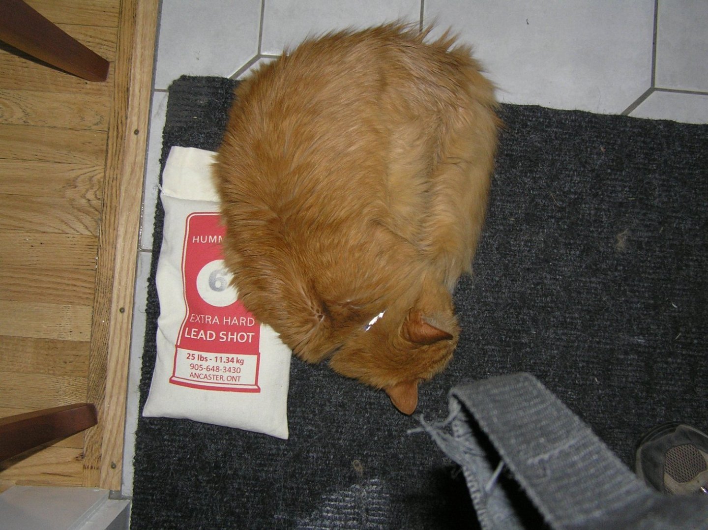
 Got the oars covered with three coats of Varathane exterior satin "Diamond Finish". Cured to a nice soft satin, surprising me with how nice the shafts look - the dowels were very pale. Here's a shot of the oars drying; just the 44 lower oars, I still have to make and finish 42 upper oars. Also went to the shooting range and bought a bag of #6 lead shot. Was interesting watching people skeet shoot while I was there. What is it with cats wanting to lie on all your stuff?
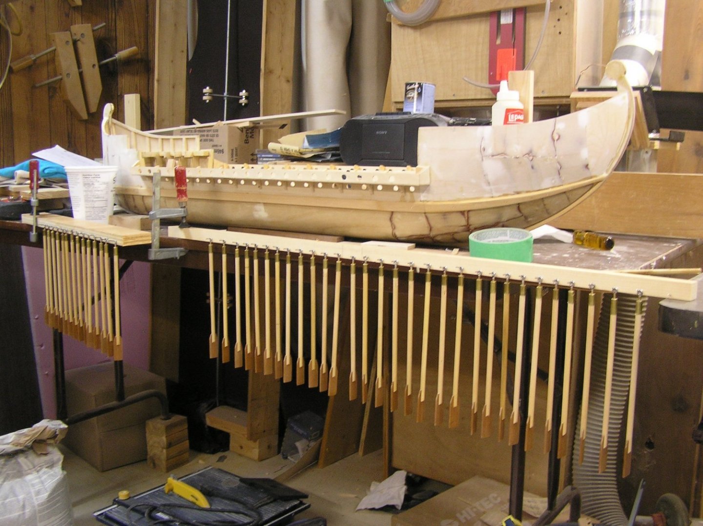
- 536 replies
-
- 9
-

-

-
- Quadrireme
- radio
- (and 1 more)
-
Interesting discussion. It prompted me to dig out my old CS instructions from the 70's, and look at the (sad state) of my CS. I see I rigged mine according to the instructions. I'll just say a few things, noting that I have no CS-specific books either. Revell shows a kink in the backstays where they meet the spreaders which is utter nonsense. As far as I've read, the spreaders should not disturb the straight run of the backstays; there should not be a bend in them at the spreaders. Revell's instructions are quite clear that the mizzen topmast has no backstays at all. This is surprising to me, unless just maybe it gives the driver gaff more space to pivot? I see I rigged mine faithful to this. Revell's "backstay #3" to the topmasts is very vague as to what happens to it at the topmast. As George says they should loop around the topmast immediately above the crosstrees but it doesn't look like that on the drawing. I see I did topmast backstays two different ways on my CS; what did the teenaged me know? Underhill shows that iron lower masts often had a pair of backstays attached to eyes welded to the lower mast's cap. Revell's "backstay #2" could be a lazy way to rig them.
- 89 replies
-
- 2
-

-
-
- Cutty Sark
- Revell
- (and 2 more)
-
Bill, those aren't supports for gammoning, they are a series of sheaves for future rigging threads which pass through them on the way to the fore rail. Make sure you have the openings through the assemblies clear of glue etc. To attach them? I would lash them, along with a little bit of CA to hold them while lashing.
- 1,508 replies
-
- 2
-
-
- Le Soleil Royal
- Heller
- (and 1 more)
-
The main mast is the only one that goes to the keel, for some reason, in this kit.
- 1,508 replies
-
- 1
-
-
- Le Soleil Royal
- Heller
- (and 1 more)
-
Thanks Steven, you mentioned this near the start of this log 😄 but it was so long ago now I guess you forgot........ 🙄 I saw that video before too. Interesting that the oars have that little pause; makes me think they aren't motor-driven. Wonder if he has a servo scheme too? Don't worry, my oars won't be going near as high as that. In fact, my galley will be calm water only, or the oars might be striking wavetops on the return stroke. I'm sure there will be a lot of software tuning once this boat is operational. Thanks, Ian
- 536 replies
-
- 5
-
-
- Quadrireme
- radio
- (and 1 more)
-
Thanks! That's a good idea.....will look into it. Don't know how big these balls of shot are......
- 536 replies
-
- 2
-
-
- Quadrireme
- radio
- (and 1 more)
-
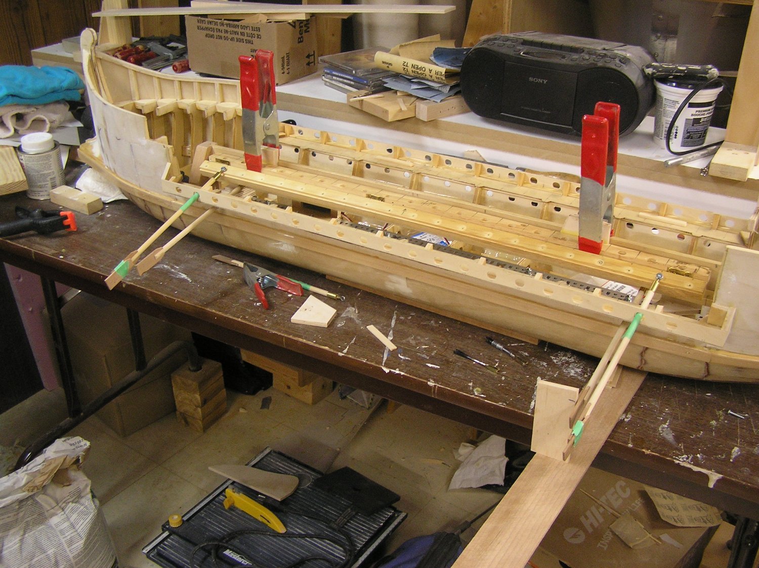
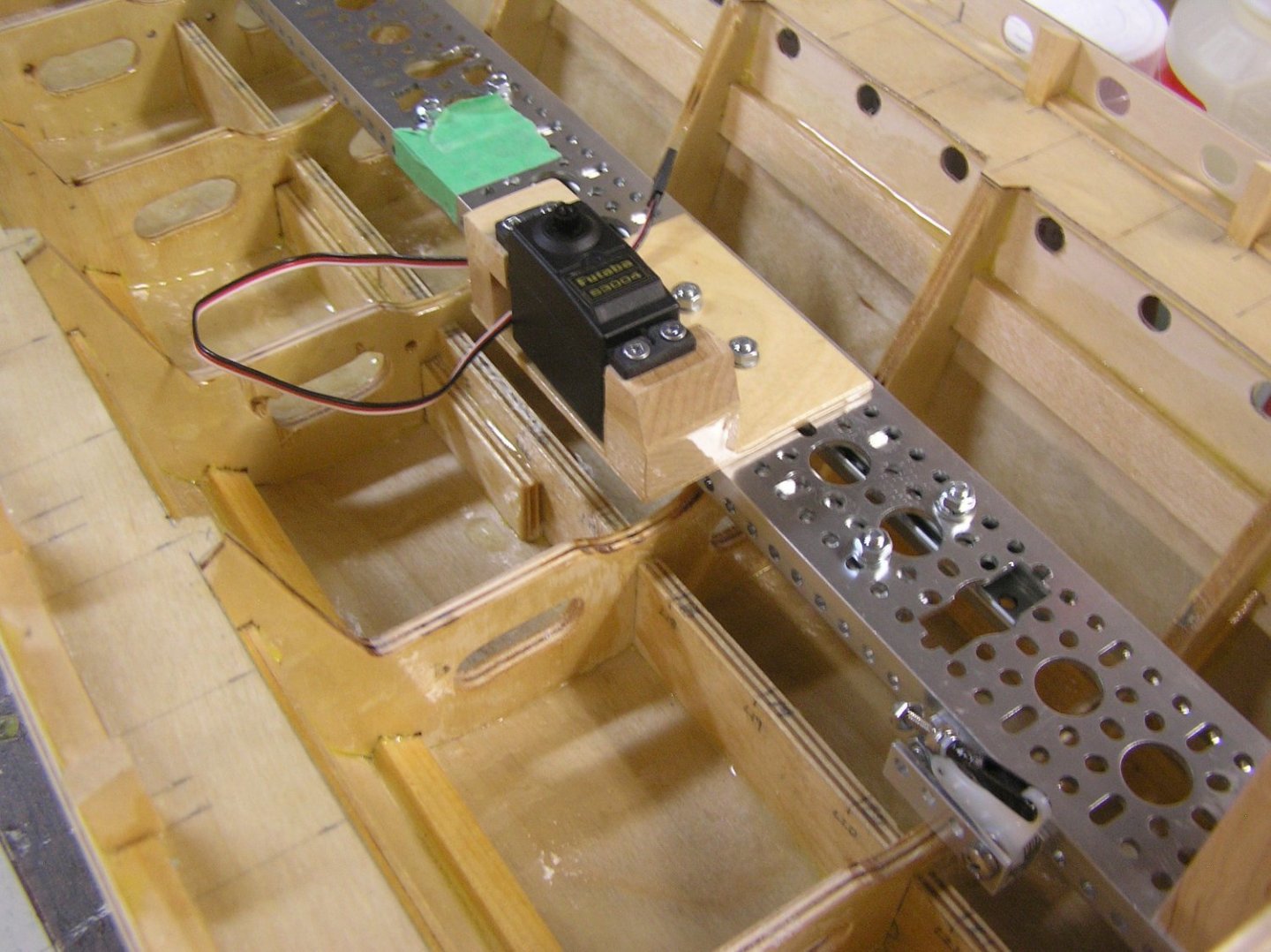
Problem solved. Port side mechanism mounted in the hull. Checking the new oar geometry will work in the hull cavity without hitting deck beams etc when blades are in the water (pic). Upper oars will be 1/2" longer than lower oars, will need to make 42 of them. Existing 44 oars will be the lowers. Found out I can buy lead shot at a nearby shooting range. Planning to buy plastic film-roll canisters to fill with shot as opposed to pouring loose shot into the hull. Snag is I must buy 25 lbs of shot 🤨, will sell the remainder on. Pic shows extra blades taped to upper oars to depict their new length. Need to sand and varnish at least 22 oars; complete the mechanism install; install the 1/4 scale sweep servo; get the shot and ballast hull; try it in the pool with just lower oars on one side to see if they get traction. If so I will spend the money and time to mechanize the starboard side and complete hull decoration and painting. Not sure if I will get the deck built this year - our summers are short and should be enjoyed.

- 536 replies
-
- 10
-
-
-
- Quadrireme
- radio
- (and 1 more)
-
By the way Glen, I think standard tile grout may be better as your wall mortar than caulk. The caulk will be hard to smooth out when dry, but grout is always just wiped smooth once partially set. No muss, no fuss.
- 290 replies
-
- 4
-
-
- Quinquereme
- Finished
- (and 1 more)
-
Glen, I realized I had forgotten your intentions for this SIB.......that last post of mine shows a Greek ship not a Roman one. There are a few drawings of Roman types at the following: https://naval-encyclopedia.com/antique-ships/roman-ships
- 290 replies
-
- 5
-
-
-
- Quinquereme
- Finished
- (and 1 more)
-
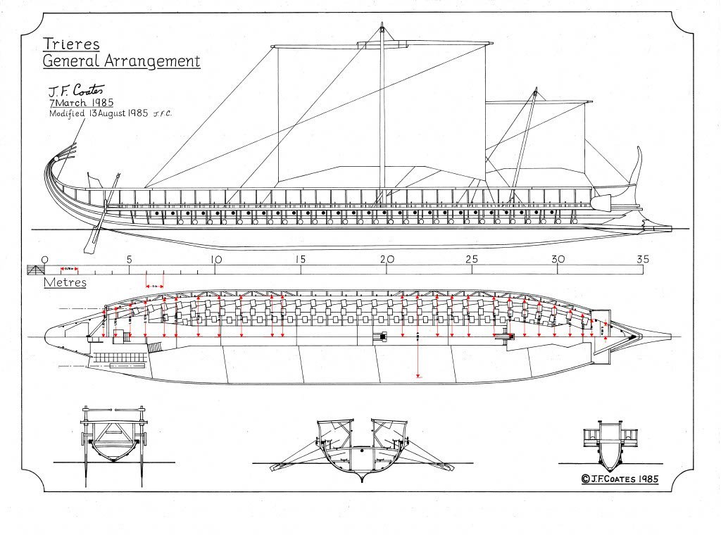
That's a very fancy impression of a trireme, perhaps envisioned as an Emperor's personal ship. A more workaday impression is the trireme "Olympias" which was built around 1990-2000, was tested with 170 volunteer rowers, and is now on display near Athens. Here is the general arrangement drawing. There are several videos on youtube. I have many more detailed drawings of her if you are interested, but for SIB this might suffice.
- 290 replies
-
- 3
-
-
- Quinquereme
- Finished
- (and 1 more)
-
I seem to have caused a fruitless digression, again. Sorry. I wasn't sure which half of the century SR was from; Andersen states that in the latter half everyone did indeed have chains. BIll, that 4th part is called the "preventer plate".
- 1,508 replies
-
- 1
-
-
- Le Soleil Royal
- Heller
- (and 1 more)
-
A plate is (was?) a single piece of metal with a hook at one end for the deadeye strop and a hole (sometimes two) at the other end to bolt to the hull. I know Dafi's SR had single plates in the form of straight bars, I've seen the photos. But he made that a long time ago; maybe he would differ now. In later centuries chains ie the 3-piece link you are used to, were used by all. But Andersen is quite definite that from 1600 to 1640 all ships used plates as he shows in the diagrams. What year is this SR supposed to be? Marc would know. As to your soldering, is the tip dirty? It needs to be cleaned and tinned for effective use.
-
Does the copper have a coating on it that you need to sand off maybe? Is that tube some kind of liquid flux? Bill, chain plates were not always like the ones on Victory. According to Andersen, all nations used plates, not chains, at least for the first forty years of the 17th century. Then everyone switched to chains for 15 years, then English ships switched back to plates. I'm not even sure what year SR purports to be from. I remember seeing Dafi's SR with plates. Take everything I say here with a grain of salt, I haven't done any research. Andersen states (twice) that chains/plates is a difficult matter.
-
It came yesterday. It's a pretty dense book, no illustrations at all except for a couple of maps of the ancient Mediterrenean. Thank goodness, it's not like reading the Iliad with all its repetition; "he fell, and his armour crashed around him". I guess because Polybius is a historian not a poet. I'll see if he mentions twin hulls. Even if he does, I'm not building one. 🙄
- 290 replies
-
- 6
-

-
-
- Quinquereme
- Finished
- (and 1 more)
-
My all-time favourite back cover work was from a guy who carves animal skulls out of burls, with the darker lines inherent in the burls looking like fused bones.....
- 2,699 replies
-
- 2
-
-
- heller
- soleil royal
- (and 9 more)
-
HaHa! I thought it was on the actual magazine's web site.....your work could well be on the back cover...........
- 2,699 replies
-
- 2
-
-
-
- heller
- soleil royal
- (and 9 more)
-
Marc, you're a dark horse..........featured in the Fine Woodworking gallery !!!!!! ...... Beautiful pieces.......Respect......
- 2,699 replies
-
- 4
-
-
-
- heller
- soleil royal
- (and 9 more)
-
Doug, I was looking for some stuff at Servocity and noticed they still sell "servo gearboxes" for those who need more torque, which reminded me of your CA build. Rereading your posts I see you mentioned the instructions show outlines for three sail servos. That being the case you can have a 785 for each sail so each one should be able to handle the pull force of its sail's sheet just fine. With all fore-and-aft rig there is no need for independent movement of sail servos (like in a model square-rigger with separate foremast brace controls to aid in tacking) so I suppose you just y-harness them all to your receiver output. Possible snag is you need different travel for each; if you can't mcgyver it you'll need to use three radio channels and get your thumbs used to the necessary stick movement patterns on your TX box. As for the mizzen, you could possibly control it's sheet from one of the three servos, if it's run is conveniently 1/2 that of one of the other sails (a movement of 1/2 is easy to achieve with a pulley).........you could adjust the position at which the sheet attaches to the yard to fine-tune the required run. When I finish my current RC build (hopefully this summer), and then finish rigging my interrupted static model, I want to build an RC square-rigger using some of the ideas in the Williams book and also those of Neville Wade who you can find on the internet. Looking forward to seeing your progress.....👍
-
You could make new davits from brass rod, chucked in a drill to taper.....then solder on copper eyes at ends. Not too hard.
- 89 replies
-
- 2
-
-
- Cutty Sark
- Revell
- (and 2 more)
-
Glen, Hope your friend makes a good recovery! The amount of rehab after a stroke is unpredictable - here's hoping she is at the easier end!!
- 290 replies
-
- 5
-
-
-
- Quinquereme
- Finished
- (and 1 more)
-
Hi Bill, no it won't cause you any construction problems. You could emulate Marc and raise the lower masts his 3/8" by adding 3/8" of some material at the lower ends to mate with the steps. Or not bother.
-
Bill the topmasts are what you are referring to as the middle section. The upper masts are the topgallant masts.
- 1,508 replies
-
- 1
-
-
- Le Soleil Royal
- Heller
- (and 1 more)
-
Bill, just a word before you proceed that the topmasts of the SR kit are widely thought to be too long. To be sent down properly after the fid is removed, their upper ends must clear the mast tops by the time their butt ends hit the deck. Obviously I haven't looked at my parts, but from the overall drawing on the first page of the instructions the fore topmast particularly looks crazy long. Andersen lists proper proportions in his book.
- 1,508 replies
-
- 1
-
-
- Le Soleil Royal
- Heller
- (and 1 more)
-
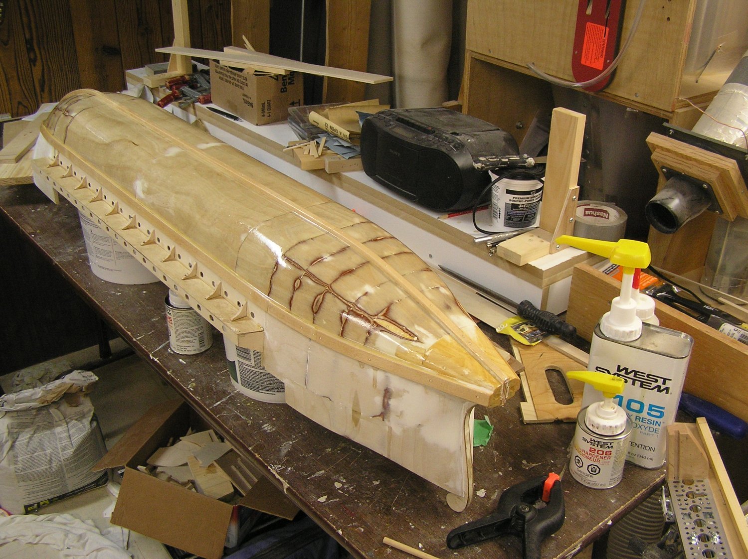
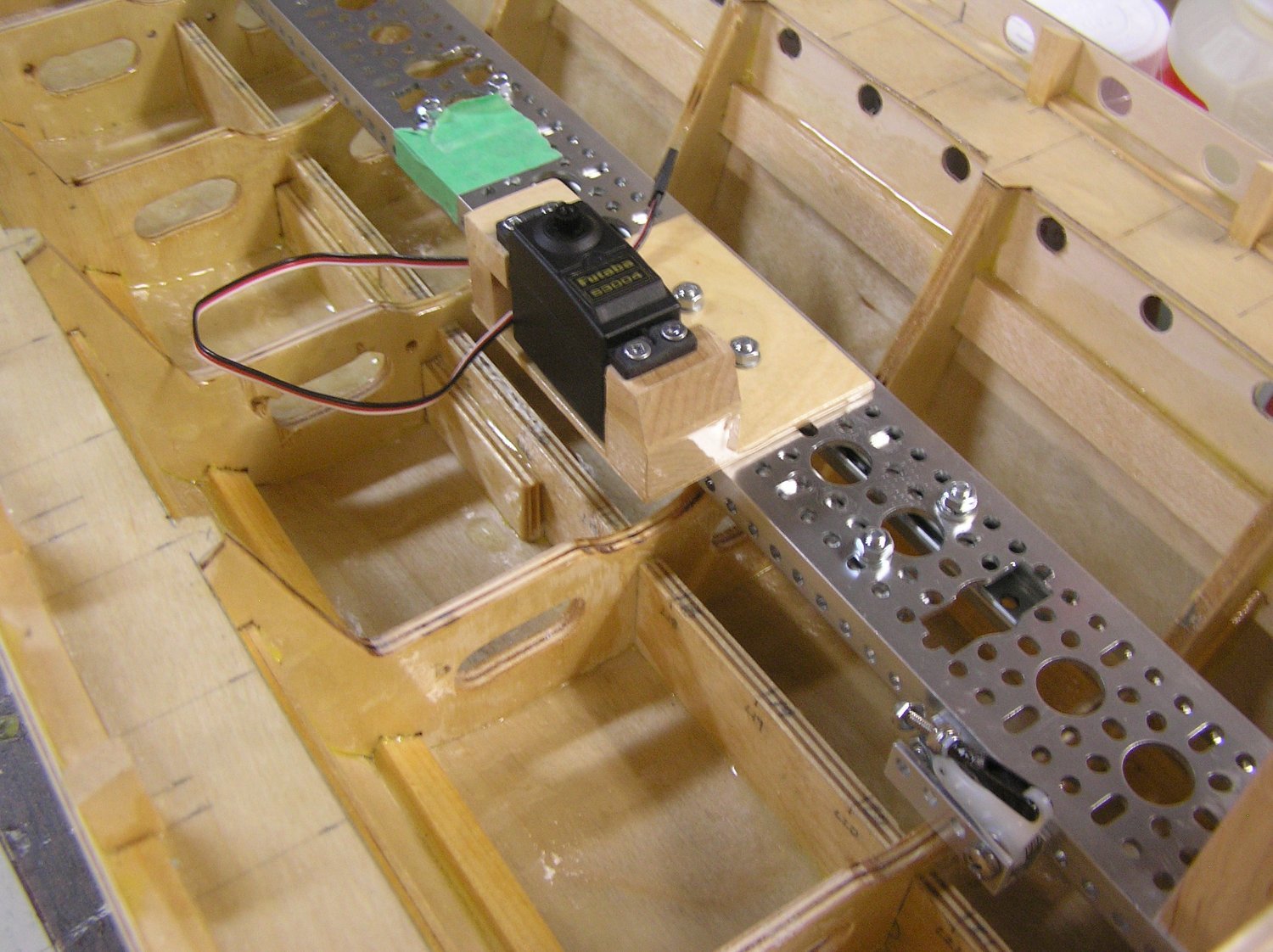
I've been preoccupied with building a new little deck to access our new above ground pool (some of you may recall the old one was crushed by a falling tree) and trying to tidy up landscape beside it after I ripped out the old pool with its external braces along the straight sides of the oval. I applied epoxy resin to the inside of the galley using West System resin and slow hardener I had left from repairing my 1:1 boat. It took AGES to dry. Before epoxying the outside underwater hull I ran out and got some fast hardener (no, not 😉Viagra). It dried quickly. Man, is it glossy! I'll be scuff sanding before painting. Now trying to install the mechanism on the port side. I ran into an issue regarding the drawer slides: I cut the ends off to save weight as discussed previously but now they have almost zero "play". They are in pairs at the ends of the aluminum channel and I'll need to screw them into their little platforms on the hull flooring exactly the right distance apart or they'll bind. This is exactly what happened on my first attempt where I just eyeballed drilling the holes on centre. I'll need to set up a little jig on the drill press to drill consistent holes. Failing that I may have to fall back on having the aluminum channel slide back and forth through two "guides" made of laminate or zero friction tape. Yuck. Some pics ...

- 536 replies
-
- 8
-
-
- Quadrireme
- radio
- (and 1 more)