Ian_Grant
-
Posts
2,156 -
Joined
-
Last visited
Content Type
Profiles
Forums
Gallery
Events
Everything posted by Ian_Grant
-
 I decided I spend WAY too much time reading news on the internet, and wasn't making any progress on the ship working in dribs and drabs. I actually spent a solid afternoon making the lower bulkheads. My new year's resolution is to cut back on computer surfing time and do something more useful. Almost anything would be.😄
- 536 replies
-
- 3
-

-
- Quadrireme
- radio
- (and 1 more)
-
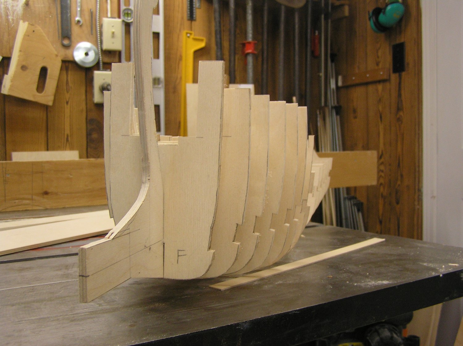
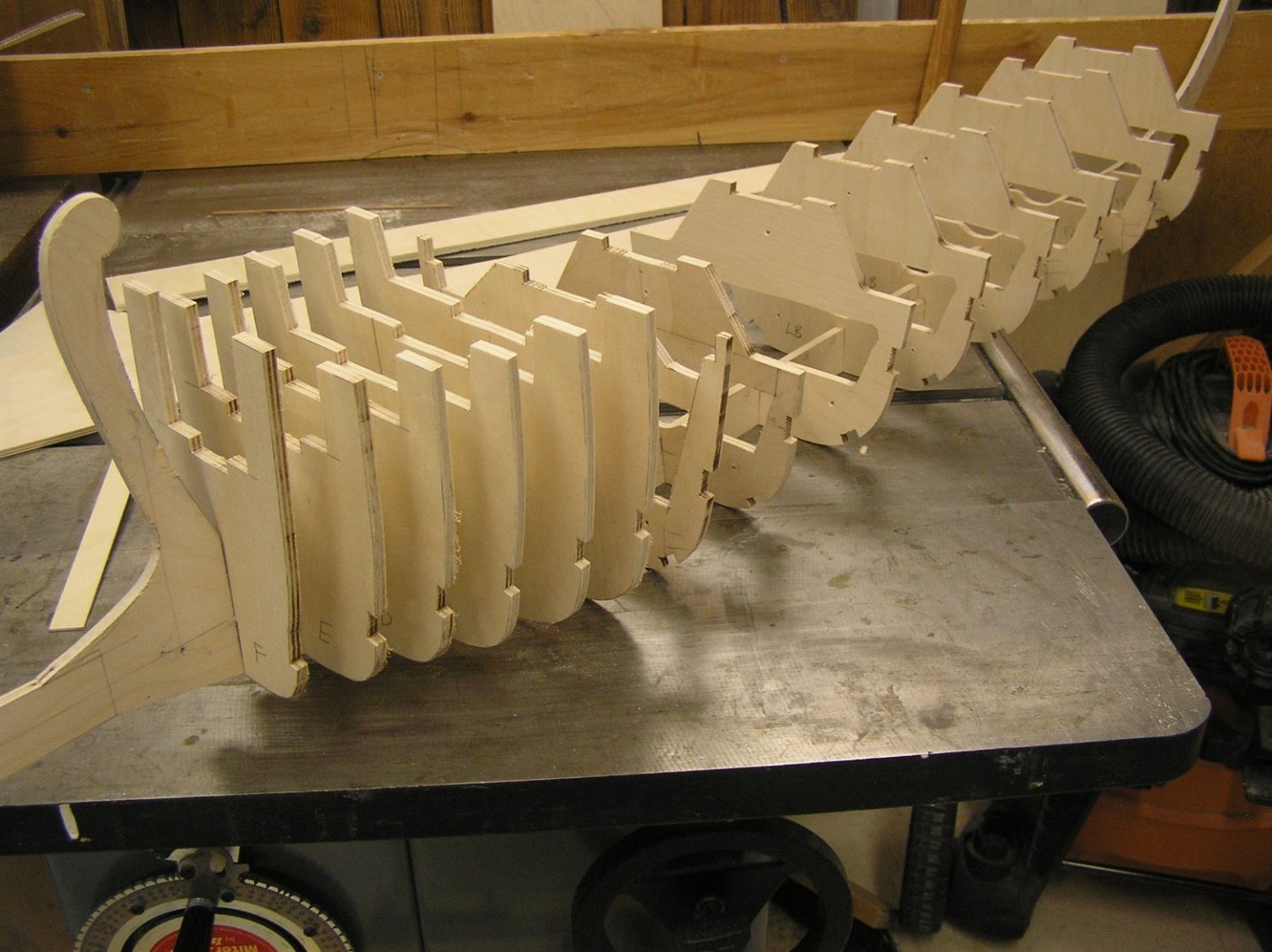
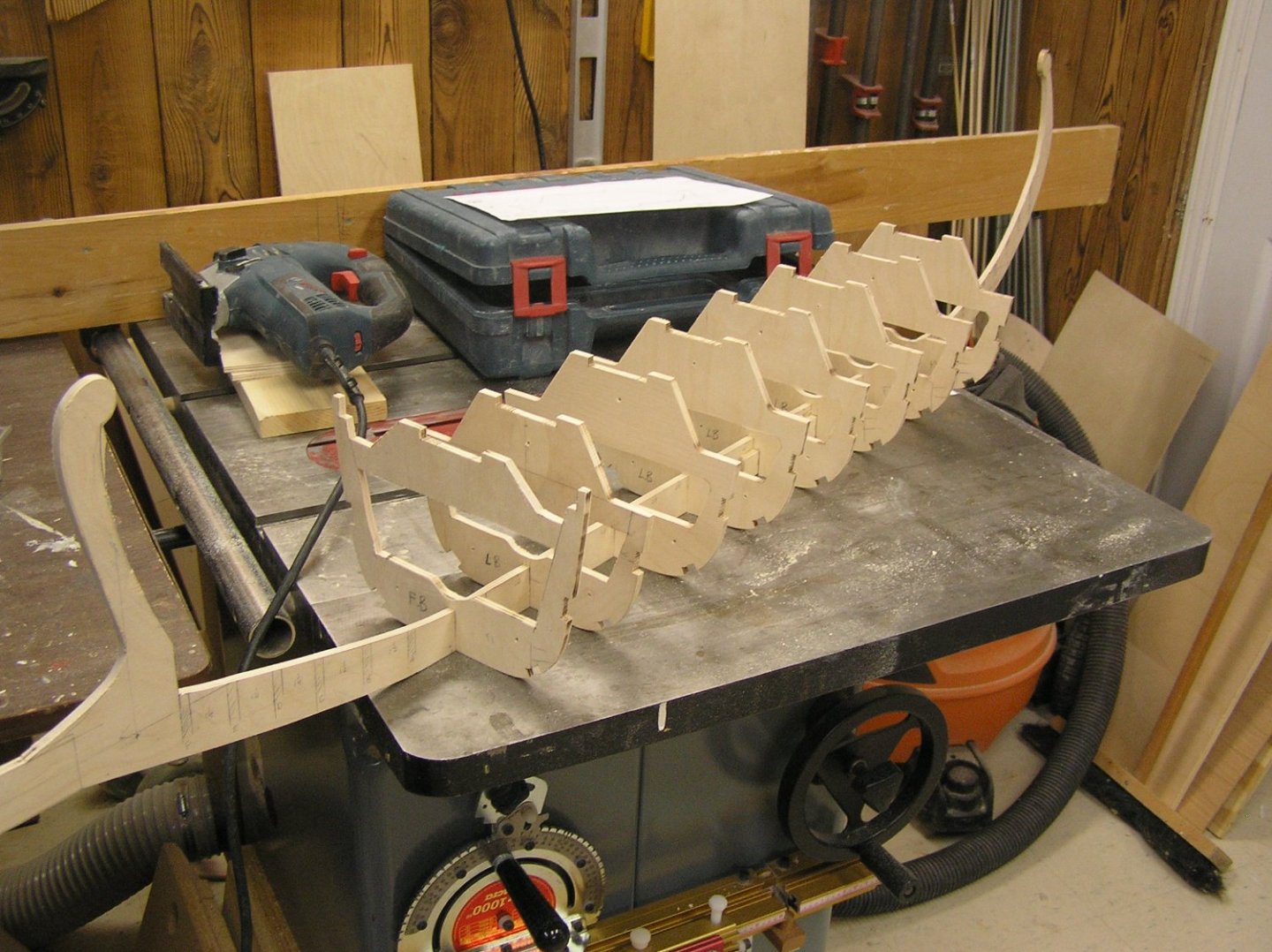
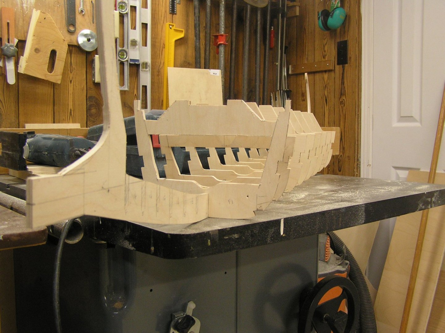
Roughed out the bow bulkheads; just their outlines without hollowing out their insides. I, umm, may have overdone it as regards their spacing. They're pretty close together. 🙄 In these pictures they're just stuck into their keel slots. Most are nice and snug, a couple a bit loose. There seems to be an alignment issue with deck level at the very front. Haven't examined it in detail. The frame as is seems quite heavy, though there is quite a bit to cut off bulkheads yet. With all the bandsaw cutoffs from sawing these out, I tried some narrow bits for strength. This baltic ply is pretty incredible, I can't break a six inch long 3/8" wide strip with hand force, so there seems to be lots of scope to make the bulkhead webs skinny and thus lighter. But now I'm worried about being able to press pins or whatever into the edges to hold ply skin down while glue dries. 😬 These bulkheads will be a bitch to fair, they're so hard. Maybe I should have used ordinary ply? Too late now. Once I figure out this alignment issue I will hollow out the bow bulkheads and see how much internal space is available for electronics. I'm now thinking battery and Arduino and possibly one sweep servo up front, lift servos and one (or both) sweep servos between the oar mechanisms, rudder servo at back. Battery up front makes sense since it only connects to the Arduino daughter board. The humpback-style NiMH pack might be better than the flat one, in this location.

- 536 replies
-
- 6
-
-
- Quadrireme
- radio
- (and 1 more)
-
Because last spring's "derecho" felled a neighbour's tree which crushed our above-ground pool, I was thinking maybe I could maiden her in the shallow pool/fountain at Nepean city hall on Centrepointe Drive, if it's deep enough, not sure. If something went amiss I could easily wade out to my ankles to retrieve it. Also not sure how "security" would react...... A swim in the pond at AH park would be pretty yucky. 😬 Apparently the Ottawa RC boat club (Rideau Nautical Modellers) sometimes uses the pond at Brown's Inlet in the Glebe. That might be nice calm location for a galley!
-
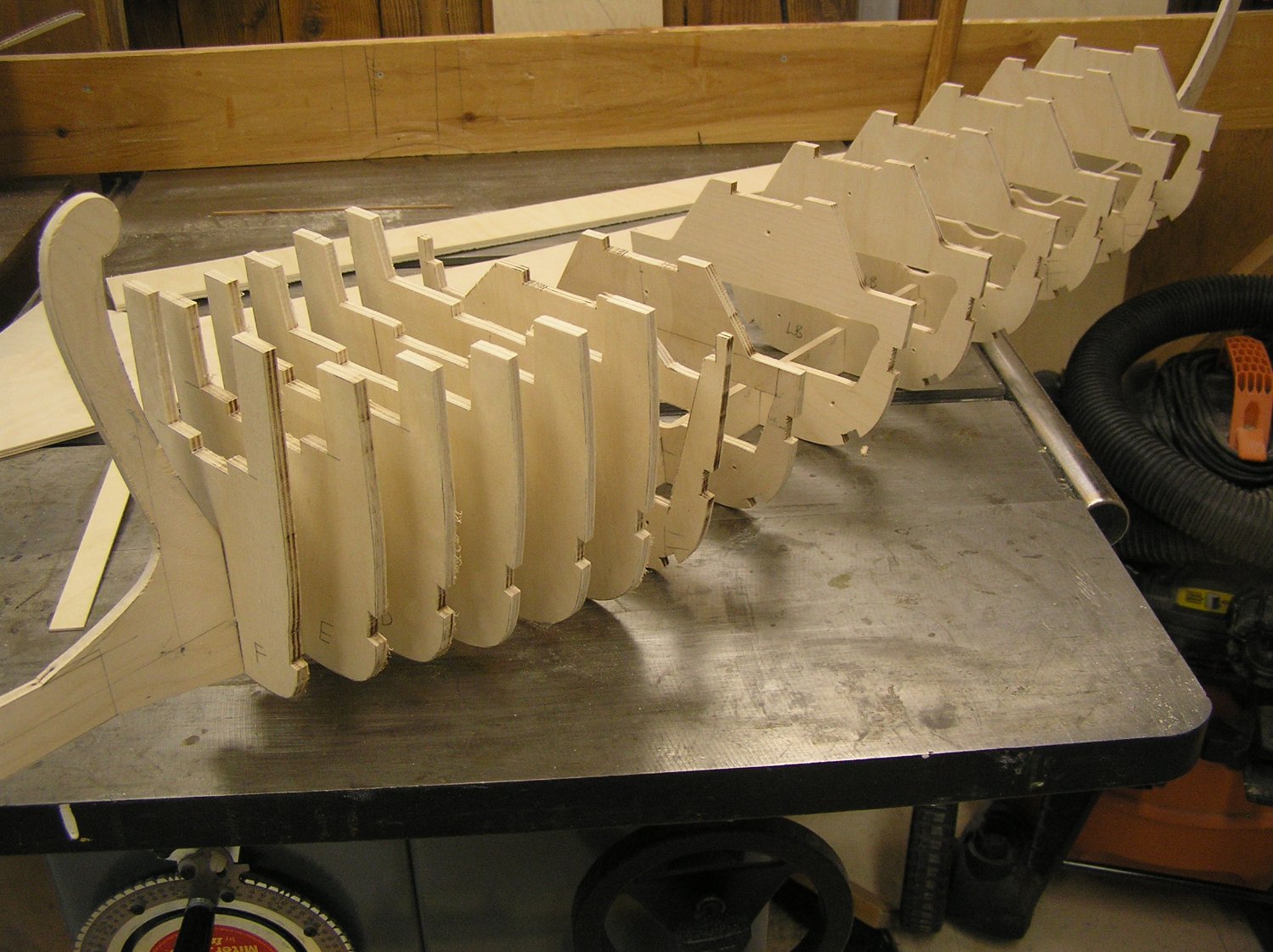
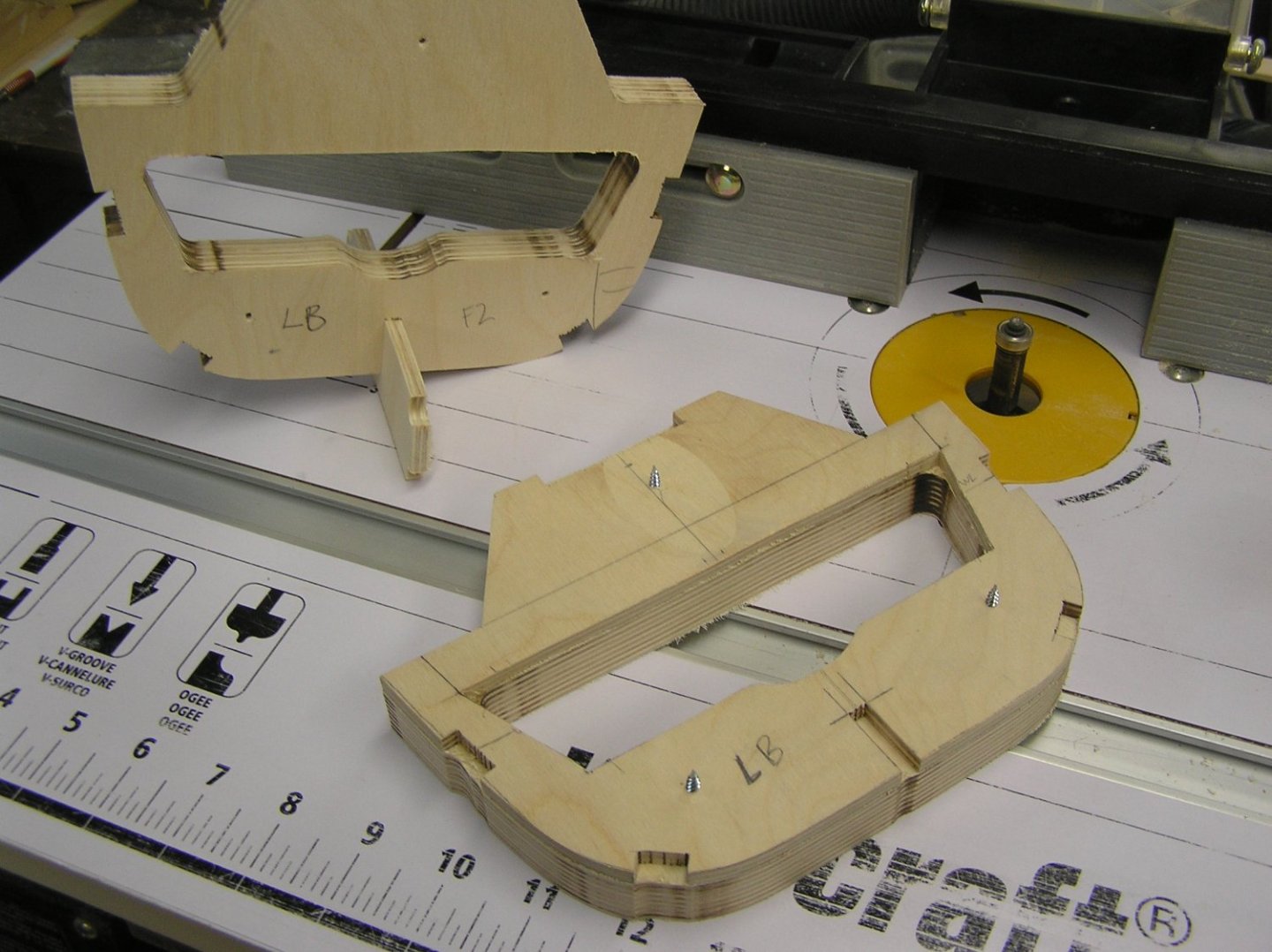
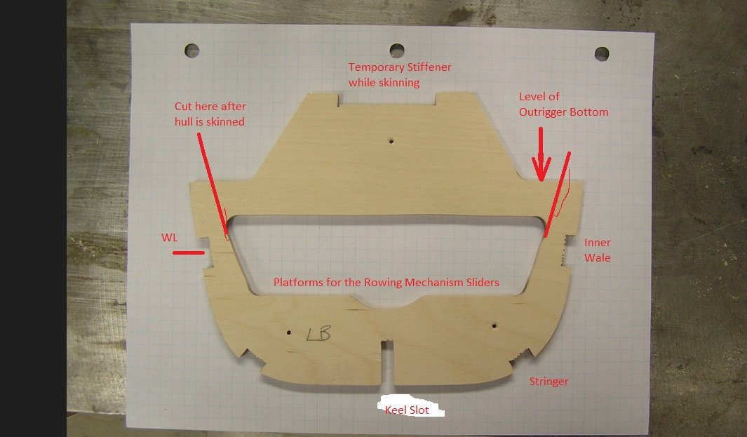
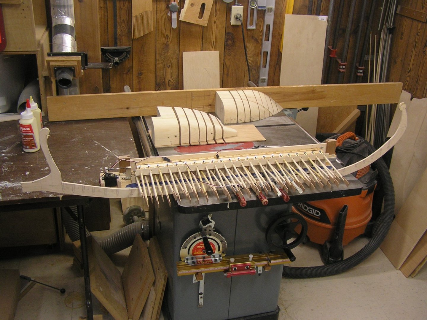
Well once again I have to walk back previous comments. I scanned my drawn bulkhead for the "engine room" central portion of the hull and imported into inkscape. I tried to understand the node and path editing, I really did, but it was just too aggravating. The last straw - I noticed a 1/8" discrepancy in a dimension; probably the fault of the printer I used to scan but it decided me to just draw the bulkheads and cut them out without benefit of a laser. The hull is a constant cross section from just in front of the first oar to a bit in front of the last oar. I was able to draw and carefully cut one bulkhead then use it as a template to gang bandsaw/router six duplicates. All without cutting my finger😁. By necessity, the "lower bulkheads" must end at the outrigger; they are spaced midway between the lower reme oars which means they are in line with those in the upper reme. "Upper bulkheads" start in the outrigger, spaced midway between upper reme oars, but can't do much more than define the slope of the outrigger top surface because if they extended further they'd interfere with those oars. I am making all bulkheads up to the level of the sub-deck so I can add a temporary wide brace along the top to hold everything in line while the hull is constructed. When I first drew the full bilge amidships I was thinking how great, I can move the mechanisms much lower down to benefit stability; but in fact I am limited by the bilge curving inward and upward in that great arc at the stern, constricting the interior volume. The platform location shown is the best I can do. At least it's 1/2" lower than the initial drawings. So here's the keel with these central bulkheads and the first one forward of them, which is beyond the oars and extends up to deck level. The rest of the bow and stern bulkheads will each be unique obviously. Looking at my traces for the stern I'm thinking I made it too much of a "vee" shape instead of a "u"; there is a fair slant at the top which if extended into the bulwarks would perhaps look odd. I will do the bow bulkheads next then worry about that. My current plan is to have fixed bulwarks at the bow and stern, with the central bulwarks lifting off with most of the deck, for access., mainly because much of the mast rigging will be on cleats on the bulwark and I don't want to unrig them every time I open the boat. I presume there was a backstay too; it could be a problem. A long time ago I said I'd extend the bow a little to increase space for electronics. Ultimately I didn't because it just looked wrong. Not sure how much space I will have now. The sweep servos may end up installed between the beams too, along with the lift servos AND I'd like to have a sturdy handle midships, attached near the keel, to help me lift what will be an awkward model with all the oars sticking out. Sorry, another wordy post. 😔
- 536 replies
-
- 7
-
-
- Quadrireme
- radio
- (and 1 more)
-
Bill, just cut the old rope, tie the new one on, and pull the new rope through using the old rope.
-
woodrat, you wouldn't happen to have a picture of what such a mast step might have looked like?
-
Me too.
-
Eugene, thanks for the link to the Nave Roman build video which I just watched. It's great! I could never get good looks at the model in the video I cited whose lighting is a bit dim. There are a couple of shots in this new video which show the "boarding bridge" lying across the foredeck in line with the gaps in the bulwarks. I was going to do the same as my target is after the corvus was obsoleted. Was hoping to get a good look at the fixture at the base of the mainmast allowing it presumably to be tilted down when unrigging which is something I will need to make. I also really like his colour scheme. Think I will do the same. Except for the planked natural areas. I'd love to get this kit.
-
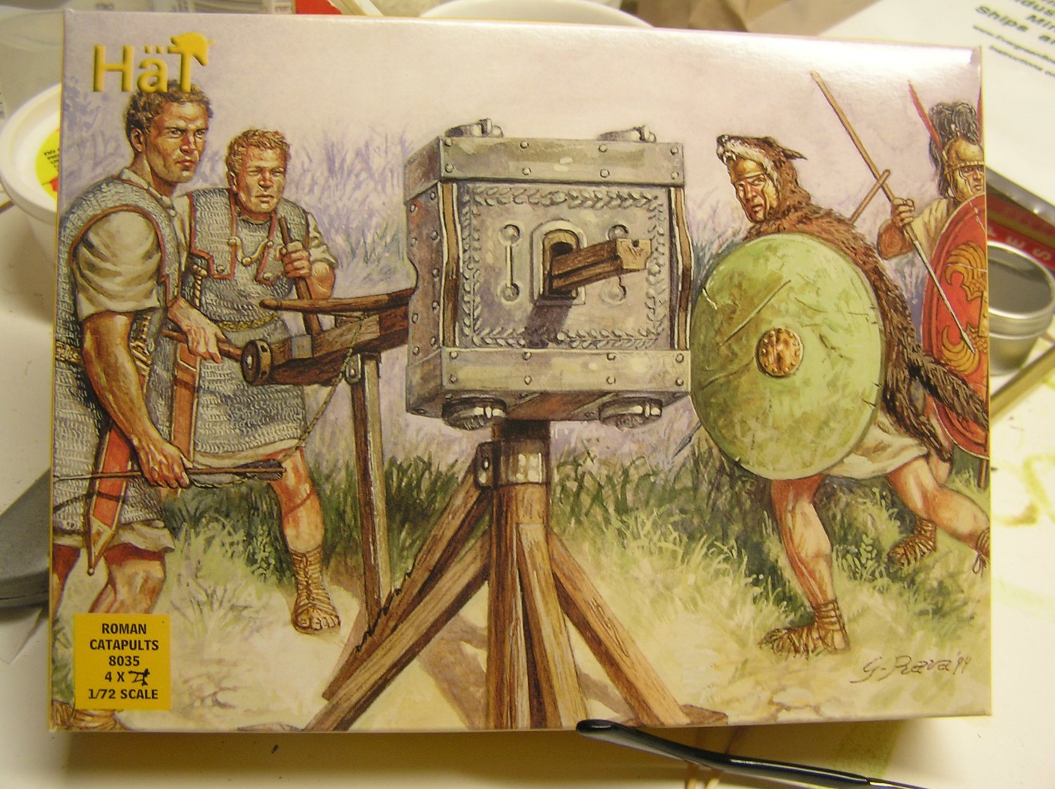
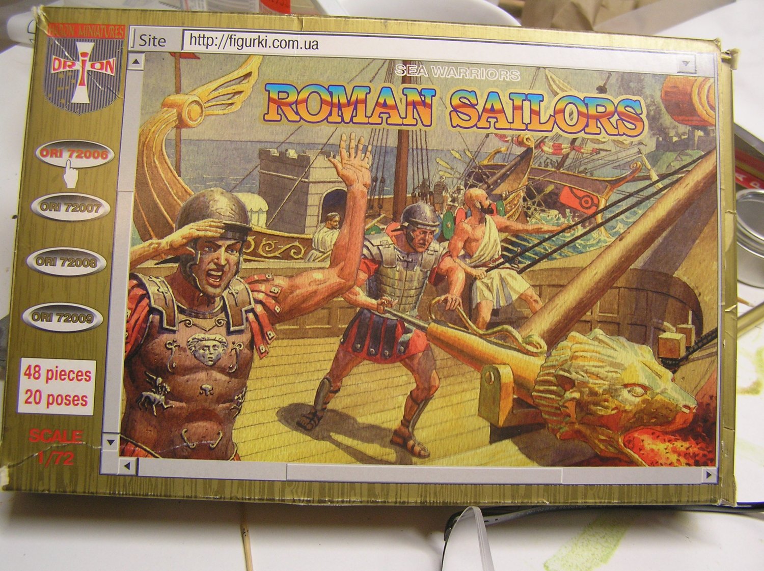
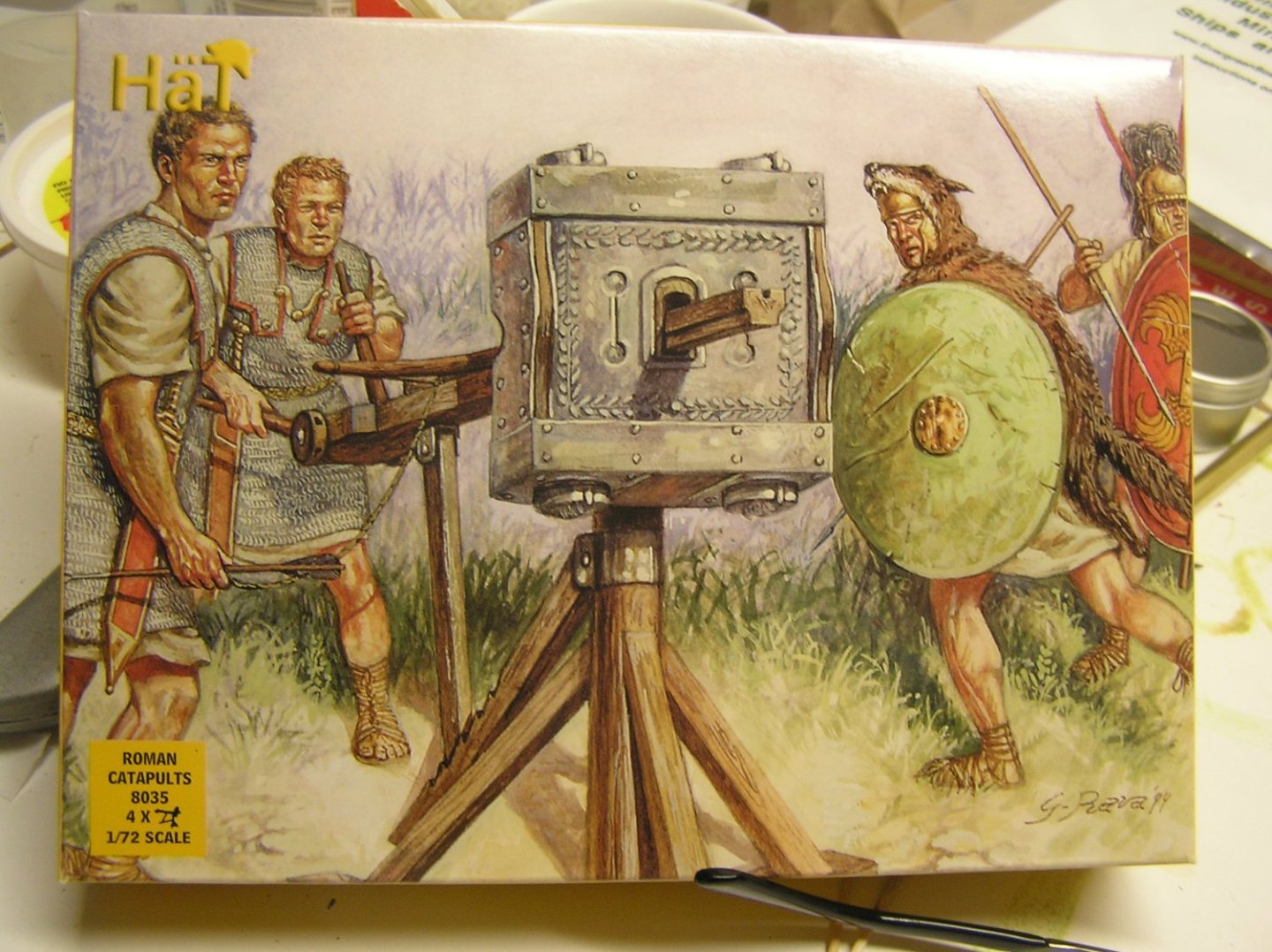
Eugene, they're the wrong scale for your model, but if a reader is considering buying the Zvezda 1/72 scale model they may be interested in these plastic figures I bought for mine:

-
Actually there are two clubs in Ottawa, one for static builds and one for RC. Sad to say I had never been to a single meeting of either (I spent 37 years NOT doing models until 2014) until just last week, when I received an invite from someone who I guess saw my location in MSW.
-
Eugene, wonderful models you have there. Seriously, you live in Ottawa too? I'm in Nepean near Greenbank and Baseline.
-
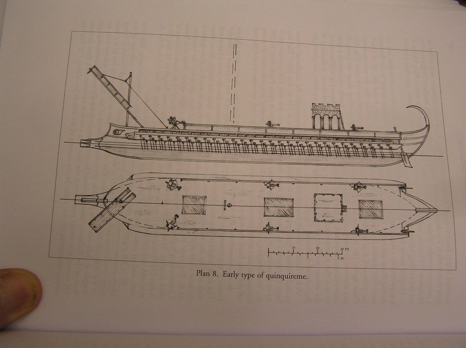
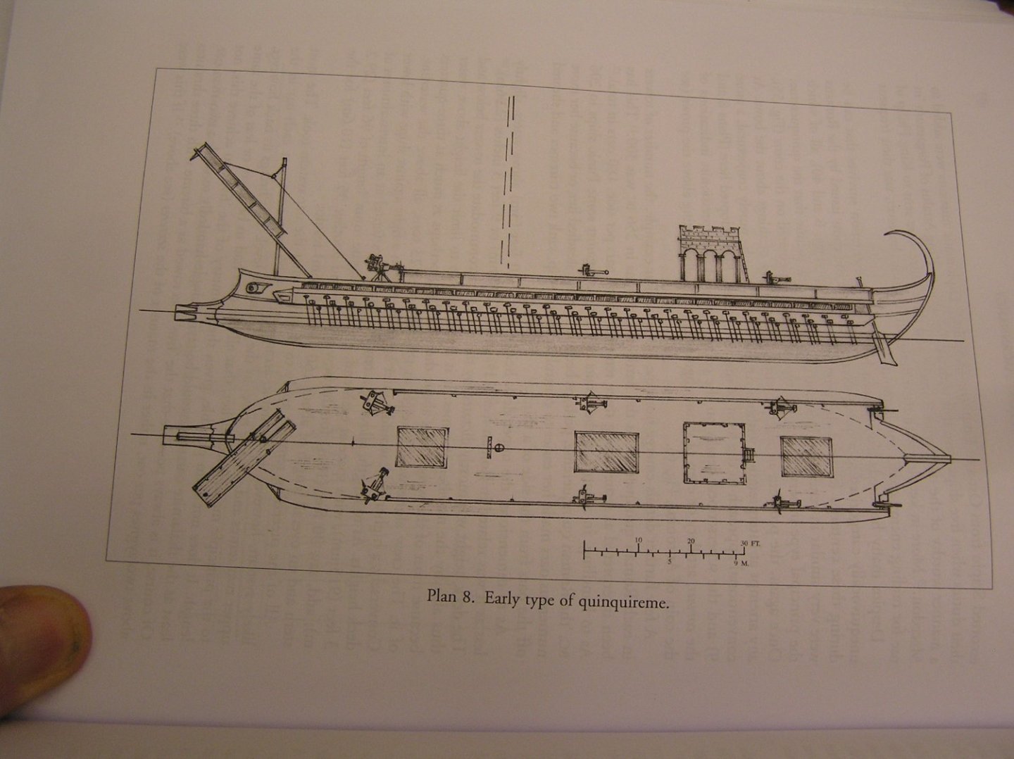
Hi Eugene; yes, my log is in the "Scratch Builds up to and including 1500" section, as is yours (see below). Pitassi shows early quinquiremes with no bow bulwarks at all, like a Greek trireme, to accommodate banging the corvus downward. Part of the reason they were un-seaworthy and so many sank in storms in the 1st Punic war. Interestingly, he mentions that uncovered wall paintings in Herculaneum, apparently depicting quadriremes across the bay at the naval base, have a central archery tower which would obviate a mast. I needed to limit my remes to two for RC, so I'm building a "quadrireme" which nonetheless will have a mast and a forward tower because they are so visually compelling. I've barely started on the hull; spent months devising and improving an oar mechanism for RC. I was tracing out my stern sections today before laser cutting (I hope) and I think I have a problem with the stern bulwarks - I didn't include them in my stern half hull carving and they're flaring out a lot if I continue my hull curves.....blah....blah......you can skip to page 6 in my log to catch up on the hull "progress" if not interested in the rowing.
-
Speaking as a scuba diver, those extracts gave me shivers. Wow! And going down on pure oxygen? Gadz!
- 65 replies
-
- 4
-
-
- X Craft
- I Love Kit
- (and 2 more)
-
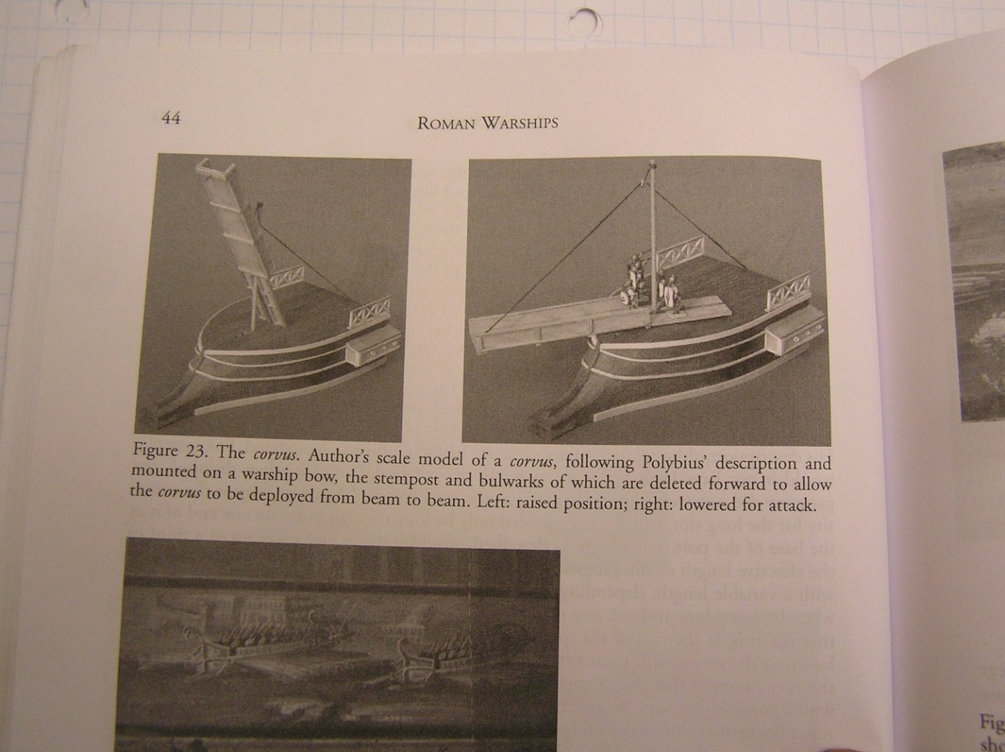
Welcome Eugene! I'm excited to see this new build - same ship as I'm doing but at a different scale. Looking forward to see how yours evolves. Scorpion, ballista, maybe Greek fire? Also the archery tower. Here's an awesome model someone made; I contacted "Cast Your Anchor" to ask about where the builder got the crewmen but they knew nothing about the model. https://m.facebook.com/Cast-Your-Anchor-Hobby-246287451905/videos/roman-navy-galley-warship-model-boat-awesome-cast-your-anchor-specializes-in-sta/325854628861004/ You may already have it but I recommend Michael Pitassi's excellent book "Roman Warships". It contains a corvus description according to the historian Polybius: ( units converted to modern usage). " A round pole about 24 feet high and 10 inches in diameter was erected on the prow of the ship. At the top of this pole was a pulley and at its base a gangway four feet in width and 36 ft in length made of planks which were nailed across each other. Twelve feet from one end of the gangway an oblong slot was cut, into which the base of the pole was fitted and each of the long sides of the gangway was protected by a rail as high as a man's knee. At the outboard end of the gangway was fixed an iron spike shaped like a pestle; this was pointed at one end and had an iron ring at the other and looked like the appliance which is used for pounding corn. A rope was passed through the ring and thence through the pulley at the top of the pole. When the ship charged an opponent, the "raven" would be hauled up by means of the pulley and then dropped onto the deck of the enemy vessel: this could be done either over the bows, or the gangway could be swivelled round if the two ships collided broadside-on. A soon as the "raven" was embedded in the planks of the deck and fastened the ships together, the soldiers would leap down onto the enemy vessel. If the two ships were alongside, they could board all the way down the hull, but if they had collided bows on, the men stayed on the gangway and advanced down it two abreast. The leading pair then protected their front by holding their shield before them, while the files who followed guarded their sides by resting the bottom of their shields on the top of the railing." Mr. Pitassi mentions that attaching the rope direct to the ring would mean an awkward moment as the marines tried to get past the rope just as they step down to the enemy deck; it would make more sense to have a yoke overhead from which two ropes attach to the sides of the gangway. Also, would not the gangway be wobbly supported by the single spike? He also puzzles over the lengthy slot in the gangway. Who knows? Polybius lived from c.200-118BC and was present at naval operations in the 3rd punic war; nearly a century after the corvus was obsoleted. Meaning neither he nor anyone he could have met could have actually seen one. Here's an image of the box art of the Zvezda Roman Galley model with a corvus interpretation. I have one in my stash; it's very nicely molded with perfect fit of parts.
-
George, I didn't know there was a naval museum in Chania! Too bad we were so focused on hiking the Samaria gorge. Next time! Our local Greek restaurant has a lovely framed poster of Chania harbour with the lighthouse and all the restaurants along the quay; fond memories!
-
Bill, the u-shaped thing is a kevel to belay lines with large pull, for example a main sheet. I have the old instruction sheets.
- 1,508 replies
-
- 1
-
-
- Le Soleil Royal
- Heller
- (and 1 more)
-
Yes, if their presence was suspected, an explosive charge dropped into the water would be very bad news for him.
- 65 replies
-
- 4
-
-
- X Craft
- I Love Kit
- (and 2 more)
-
Yes, the Ottawa Library and the US Embassy (??!) collaborated to open a makerspace which is a room called the "Imagine Space" which has two laser cutters and I think three 3D printers. It just so happens to be at the branch nearest us. The laser cutters handle max sheets of 12"x 24" and 18"x 24" respectively. I also saw someone using a pressing machine to make buttons ie the type with a metal back and a plasticized picture on the front that you pin to your clothes. Someone else appeared to be doing something with cloth material; wasn't paying attention. Clarification: the galley keel was manually jigsawed from my 1/4" plywood scrap.
- 536 replies
-
- 2
-
-
- Quadrireme
- radio
- (and 1 more)
-
Thanks Glen for the fly tying information. And your sails are great!
- 134 replies
-
- 4
-
-
- Captain Kidd
- bottle
- (and 3 more)
-
Glen, that ship is outstanding! Would fly-tying thread work for ratlines on a 1/150 ship or is it too thin? Asking for a friend. He knows nothing about fly fishing - is it easily tied into compact knots? What kind of glue to lock them?
- 134 replies
-
- 4
-

-
-
- Captain Kidd
- bottle
- (and 3 more)
-
Bless you!!
-
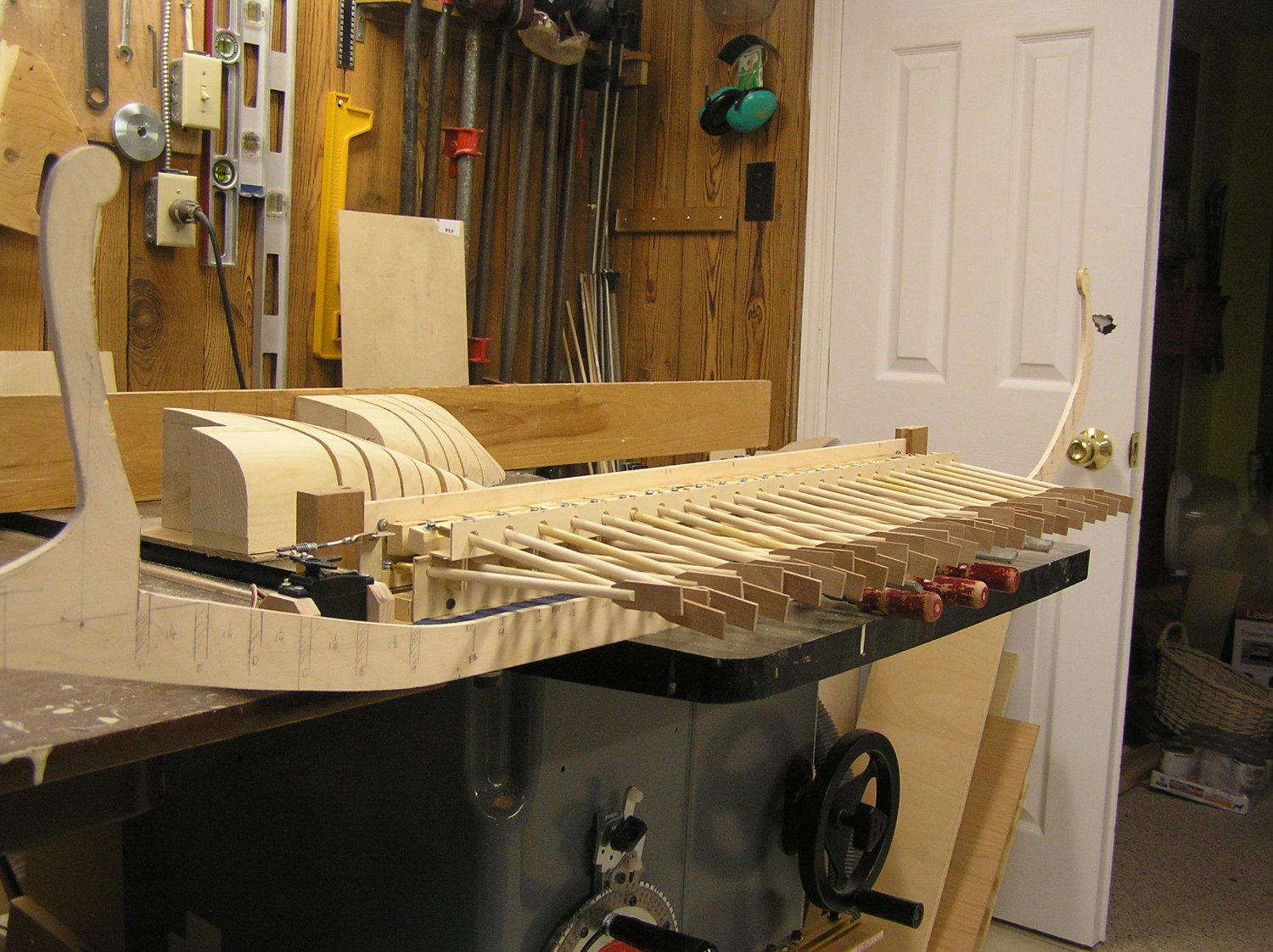
I decided to slice up my carved half hulls anyway. Traced those for the bow onto paper, scanned it, and imported into InkScape with the plan being to copy each trace then mirror and add as the other side (to guarantee symmetry), and then draw in the notches for stringers. But I got lost in all the intricacies of path and node editing (don't ask!). Decidedly not my cup of tea. I went to the library with a couple of basic questions for the people there in the "Imagine Space"; a girl showed me a bunch of stuff with fingers just flying over function keys and mouse buttons. Whew! I think she could probably do what I want to do in half an hour but on returning home I found I was just getting angry at it. Even with a large book about InkScape at hand which I borrowed from the library, but the author just dives right in. It's more like a reminder for experienced users of functions and keys, than a beginner's primer. Plus I'm a computer idiot. So I'm just going to draw my bulkheads the old fashioned manual way, and scan them in for the laser cutter, which will at least save me the trouble of jigsawing them all out and carefully sanding the contours. The laser will very accurately render any wobbly drawn lines of mine 🙄. Here's a pic of the two-piece keel moments after gluing with some gussets, with the oar mechanism just sat beside it to enhance imagining the final ship. I'm putting lots of ribs at the bow and stern to allow skinning these compound curves in pieces of 1/32" plywood. The sliced-up bow and stern sections are in the background. Note that the oars are sitting far lower than in the finished hull. I didn't pile enough wood scraps under them to raise them to design position. Oops I see I also missed cutting a little bit at the stem. She'll be a big beast - just over 53" from the business end of the ram to the stern extremity - I'm getting excited now!!!

- 536 replies
-
- 8
-

-
-
- Quadrireme
- radio
- (and 1 more)
-
What about a frogman alongside it? Or am I thinking of midget subs?
- 65 replies
-
- 3
-
-
- X Craft
- I Love Kit
- (and 2 more)